EP1532024B1 - Airbagmodul mit gasgenerator - Google Patents
Airbagmodul mit gasgenerator Download PDFInfo
- Publication number
- EP1532024B1 EP1532024B1 EP03792145A EP03792145A EP1532024B1 EP 1532024 B1 EP1532024 B1 EP 1532024B1 EP 03792145 A EP03792145 A EP 03792145A EP 03792145 A EP03792145 A EP 03792145A EP 1532024 B1 EP1532024 B1 EP 1532024B1
- Authority
- EP
- European Patent Office
- Prior art keywords
- gas generator
- airbag module
- closure element
- module
- closed
- Prior art date
- Legal status (The legal status is an assumption and is not a legal conclusion. Google has not performed a legal analysis and makes no representation as to the accuracy of the status listed.)
- Expired - Lifetime
Links
- 239000007789 gas Substances 0.000 claims description 78
- 239000011324 bead Substances 0.000 claims description 10
- 238000009434 installation Methods 0.000 claims description 8
- 230000001960 triggered effect Effects 0.000 claims description 2
- 230000006978 adaptation Effects 0.000 description 1
- 238000007789 sealing Methods 0.000 description 1
Images


Classifications
-
- B—PERFORMING OPERATIONS; TRANSPORTING
- B60—VEHICLES IN GENERAL
- B60R—VEHICLES, VEHICLE FITTINGS, OR VEHICLE PARTS, NOT OTHERWISE PROVIDED FOR
- B60R21/00—Arrangements or fittings on vehicles for protecting or preventing injuries to occupants or pedestrians in case of accidents or other traffic risks
- B60R21/02—Occupant safety arrangements or fittings, e.g. crash pads
- B60R21/16—Inflatable occupant restraints or confinements designed to inflate upon impact or impending impact, e.g. air bags
- B60R21/20—Arrangements for storing inflatable members in their non-use or deflated condition; Arrangement or mounting of air bag modules or components
- B60R21/217—Inflation fluid source retainers, e.g. reaction canisters; Connection of bags, covers, diffusers or inflation fluid sources therewith or together
- B60R21/2171—Inflation fluid source retainers, e.g. reaction canisters; Connection of bags, covers, diffusers or inflation fluid sources therewith or together specially adapted for elongated cylindrical or bottle-like inflators with a symmetry axis perpendicular to the main direction of bag deployment, e.g. extruded reaction canisters
Definitions
- the invention relates to an airbag module with gas generator according to the preamble of claim 1.
- gas generators for airbag modules which have a plurality of Abtrömö réelleen from which emerge after ignition of the gas generator necessary for the deployment of the gas bag gases.
- the outflow openings are arranged so that the gas generator, when accidentally ignited, operates without shudder before installation, that is, it does not act like a rocket engine.
- the outflow openings must therefore be evenly distributed on the circumference of the gas generator.
- an annular gap between the gas generator and the module housing or a diffuser is provided, as for example DE 195 06 886 A1 or US 6,126,195 is known.
- the gases produced in the gas generator are collected and directed with the aim of achieving a good airbag deployment.
- the disadvantage of these arrangements is that the size of the airbag module is increased by the annular gap and gas passages around the gas generator. Furthermore, the housing of the airbag module is exposed to high mechanical stress by the gas pressure when the gas generator is triggered due to large projected areas. Therefore, the module must have a high strength. For example, many screws must be used. Because of the required high strength results in an increased weight. Furthermore, due to the gas deflection energy losses and leakage through the module housing is the risk of gas losses.
- the invention is based on the object in an airbag module with gas generator, which has a plurality of distributed over its circumference discharge openings, in particular at least two opposite outflow openings, to avoid the annular gap.
- an airbag module with a gas generator in particular with tubular gas generator having a plurality of distributed over its circumference discharge openings for the resulting gases after ignition
- at least one of the outflow openings in the gas generator during installation or after installation in the airbag module closable and the gas generator is in one Fixed module housing, which has a closure element in the region of each opening to be closed of the gas generator.
- closure element preferably has the diameter of the outflow opening. But also a conical closure is possible. Compared to a flat closure in which this rests only on the discharge opening, there is the advantage that an increased security of the seal is achieved.
- a separate stopper is provided as a closure element for each outlet opening to be closed.
- the gas generator is mounted in a module housing, this has in a further embodiment in the region of each opening of the gas generator to be closed a closure element.
- the closure element is thus an integral part of the module housing.
- the invention can be used advantageously in particular when using tubular gas generators, with the module housing in the area of each of the outflow openings of the tubular gas generator to be closed being in close contact with the same. It is expedient that the module housing has a cylindrical projection or a bead at each opening to be closed as a closure element.
- the module housing in the region of the gas generator in the form of a matched to the generator housing half-shell and for fixing the gas generator, a holding plate is provided in the module housing.
- the module housing is formed as a cylindrical half-shell, which is associated with a cylindrical half-shell as a holding plate.
- the retaining plate has directed beads in the direction of the gas generator, and that the retaining plate has at least one closure element, i. that each gas generator opening to be closed, which is located in the region of the retaining plate, is assigned to this a closure element. It is also appropriate that a bead is provided in the retaining plate as a closure element.
- a module housing 1 in which a tubular gas generator 2 is fixed. This has opposite outlet openings 3, 4, so that it works in the event of accidental ignition in free space without shaking.
- the module housing is formed in the lower portion as a half-shell 1a, which also has a cylindrical plug 5 as a closure element for the discharge opening 4. Both have the same diameter with the necessary tolerances, on the one hand to be able to insert the plug into the outlet and on the other hand to ensure the seal.
- the tube gas generator 2 is close to the half-shell 1a.
- the attachment of the tube gas generator 2 in the module housing 1 by means of a holding plate 6, which is connected by means of screws 7 and nuts 8 to the module housing and thereby pushes the tube gas generator 2 against the half-shell 1a.
- the holding plate 6 is also formed as a half-shell.
- the gases from the gas generator can flow largely through the outflow opening 3 and through an adjacent opening 6a in the holding plate 6 only in the direction of the gas bag 10.
- a small amount of gas passes through the conditional by the beads 9 gap, through relief openings 6b and frontal openings 6c also only in the direction of the airbag 10, as from the FIGS. 1 and 2 is apparent.
- the embodiment of the Fig. 3 differs from the embodiment of the FIGS. 1 and 2 in that a separate stopper 11 is provided as a closure element for the discharge opening 4 and a smooth half-shell 1 b. Due to the close fitting to the tubular gas generator 2 half shell 1b is ensured in this embodiment that the plug 11 after ignition of the gas generator is not pushed out of the discharge opening 4.
- the non-referenced parts correspond to those in the FIGS. 1 and 2 shown.
- a bead 12 is provided in a half-shell 1c as a closure element.
- the bead does not fill the entire outflow opening 4, but the seal takes place at the outer edge 3a.
- a tube gas generator 13 with six opposite outflow openings 14 - 19 are provided.
- the tubular gas generator is arranged in a module housing 20 which is aligned on one side.
- the outflow openings 14, 15, 18 and 19 are closed.
- a lower half-shell 20a of the module housing 20 is provided with sealing plugs 22, 24 and 25, which engage in the outflow openings 14, 18 and 19.
- a holding plate 26 has a bead 23 for the closure of the discharge opening 15. This ensures that gases from the gas generator after its ignition mostly only from the outflow openings 16 and 17 and through the adjacent openings 16a, b in the holding plate 26 can flow into the gas bag.
Landscapes
- Engineering & Computer Science (AREA)
- Mechanical Engineering (AREA)
- Air Bags (AREA)
Description
- Die Erfindung betrifft ein Airbagmodul mit Gasgenerator nach dem Oberbegriff des Anspruchs 1.
- Es sind Gasgeneratoren für Airbagmodule bekannt, die mehrere Abtrömöffnungen aufweisen, aus denen nach Zündung des Gasgenerators die für das Entfalten des Gassacks notwendigen Gase austreten. Aus Sicherheitsgründen sind die Abströmöffnungen so angeordnet, daß der Gasgenerator bei versehentlicher Zündung vor seinem Einbau schubfrei arbeitet, d.h., daß er nicht wie ein Raketentriebwerk wirkt. Die Abströmöffnungen müssen deshalb gleichmäßig am Umfang des Gasgenerators verteilt sein.
- Nach dem Einbau des Gasgenerators in das Airbagmodul sollen die Gase aber in Richtung des Gassacks strömen, d.h. sie müssen umgelenkt werden, da sie aus dem Gasgenerator in unterschiedliche Richtungen strömen. Deshalb ist im Airbagmodul ein Ringspalt zwischen Gasgenerator und Modulgehäuse bzw, einem Diffusor vorgesehen, wie es z.B. aus
DE 195 06 886 A1 oderUS 6 126 195 bekannt ist. Im Ringspalt werden die im Gasgenerator produzierten Gase gesammelt und mit dem Ziel gerichtet, eine gute Gassackentfaltung zu erreichen. - Der Nachteil dieser Anordnungen besteht darin, daß die Baugröße des Airbagmoduls durch den Ringspalt und Gaskanäle um den Gasgenerator erhöht wird. Weiterhin wird das Gehäuse des Airbagmoduls durch den Gasdruck bei Auslösung des Gasgenerators aufgrund großer projizierter Flächen einer hohen mechanischen Beanspruchung ausgesetzt. Deshalb muß das Modul eine hohe Festigkeit aufweisen. So müssen zum Beispiel viele Schrauben verwendet werden. Wegen der erforderlichen hohen Festigkeit ergibt sich ein erhöhtes Gewicht. Weiterhin entstehen durch die Gasumlenkung Energieverluste und durch Leckagen im Modulgehäuse besteht das Risiko von Gasverlusten.
- Aus dem
US-Patent 5 480 185 ist ein Gasgenerator bekannt, der nur eine Abströmöffnung in Richtung eines Diffusors aufweist. Dieser Gasgenerator kann deshalb vor dem Einbau nicht schubfrei arbeiten und entspricht damit nicht den hohen Sicherheitsanforderungen. Weiterhin ist mit diesem Gasgenerator eine Anpassung an besondere Anordnungen des Gassacks nicht möglich. Der zusätzlich angeordnete Diffusor verursacht zusätzliche Kosten. - Der Erfindung liegt die Aufgabe zugrunde, bei einem Airbagmodul mit Gasgenerator, der mehrere über seinem Umfang verteilte Abströmöffnungen, insbesondere mindestens zwei gegenüberliegende Abströmöffnungen aufweist, den Ringspalt zu vermeiden.
- Erfindungsgemäß wird das gemäß den Merkmalen des Anspruchs 1 erreicht.
- Bei einem Airbagmodul mit Gasgenerator, insbesondere mit Rohrgasgenerator, der mehrere über seinen Umfang verteilte Abströmöffnungen für die nach seiner Zündung entstehenden Gase aufweist, ist erfindungsgemäß mindestens eine der Abströmöffnungen im Gasgenerator während des Einbaus oder nach dem Einbau im Airbagmodul verschließbar und der Gasgenerator ist in einem Modulgehäuse befestigt, das im Bereich jeder zu verschließenden Öffnung des Gasgenerators ein Verschlußelement aufweist. Dadurch ist es möglich, daß bei der Verwendung von Gasgeneratoren, die bei Zündung im freien Raum schubfrei arbeiten, nach dem Einbau des Gasgenerators in das Airbagmodul nur Abströmöffnungen geöffnet sind, die in eine gewünschte Richtung wirksam sind, d.h. vornehmlich in Richtung des Gassacks. Da die gegenüberliegenden, vom Gassack wegweisenden Abströmöffnungen verschlossen sind, kann der Ringspalt für die Umlenkung der Gase in Richtung des Gasacks entfallen.
- Es ist zweckmäßig, daß für jede zu verschließende Abströmöffnung ein in diese eingreifendes Verschlußelement vorgesehen ist. Dabei weist das Verschlußelement vorzugsweise den Durchmesser der Abströmöffnung auf. Aber auch ein konischer Verschluß ist möglich. Gegenüber einem flächigen Verschluß, bei dem dieser nur auf der Abströmöffnung aufliegt, besteht der Vorteil, daß eine erhöhte Sicherheit der Abdichtung erreicht wird.
- In einer Ausführungsform ist für jede zu verschließende Abströmöffnung ein separater Verschlußstopfen als Verschlußelement vorgesehen.
- Wenn der Gasgenerator in einem Modulgehäuse befestigt ist, weist dieses in einer weiteren Ausführungsform im Bereich jeder zu verschließenden Öffnung des Gasgenerators ein Verschlußelement auf. Bei dieser Ausführungsform ist das Verschlußelement also integrierter Bestandteil des Modulgehäuses.
- Die Erfindung ist insbesondere bei der Verwendung von Rohrgasgeneratoren vorteilhaft verwendbar, wobei das Modulgehäuse im Bereich jeder der zu verschließenden Abströmöffnungen des Rohrgasgenerators eng an diesem anliegt. Es ist zweckmäßig, daß das Modulgehäuse an jeder zu verschließenden Öffnung als Verschlußelement einen zylindrischen Ansatz oder eine Sicke aufweist.
- In einer Ausführungsform weist das Modulgehäuse im Bereich des Gasgenerators die Form einer an das Generatorgehäuse angepaßten Halbschale auf und zur Fixierung des Gasgenerators ist im Modulgehäuse ein Halteblech vorgesehen.
- Bei Verwendung eines zylindrischen Rohrgasgenerators ist das Modulgehäuse als zylindrische Halbschale ausgebildet, der eine zylindrische Halbschale als Halteblech zugeordnet ist. Es ist zweckmäßig, daß das Halteblech in Richtung des Gasgenerators gerichtete Sicken aufweist, und daß das Halteblech mindestens ein Verschlußelement aufweist, d.h. daß jeder zu verschließenden Gasgeneratoröffnung, die sich im Bereich des Halteblechs befindet, an diesem ein Verschlußelement zugeordnet ist. Es ist weiterhin zweckmäßig, daß als Verschlußelement eine Sicke im Halteblech vorgesehen ist.
- Die Erfindung soll in Ausführungsbeispielen anhand von Zeichnungen näher erläutert werden. Es zeigen:
- Fig. 1
- einen Längsschnitt durch eine erste Ausführungsform;
- Fig. 2
- einen Querschnitt II-II der Anordnung nach
Fig. 1 ; - Fig.3
- einen Querschnitt durch eine zweite Ausführungsform;
- Fig. 4
- einen Querschnitt durch eine dritte Ausführungsform;
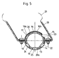
- Fig. 5
- einen Querschnitt durch eine vierte Ausführungsform.
- In der
Fig. 1 ist ein Modulgehäuse 1 dargestellt, in dem ein Rohrgasgenerator 2 befestigt ist. Dieser weist gegenüberliegende Abströmöffnungen 3, 4 auf, so daß er im Falle einer versehentlichen Zündung im freien Raum schubfrei arbeitet. - Das Modulgehäuse ist im unteren Abschnitt als Halbschale 1a ausgebildet, die außerdem einen zylindrischen Verschlußstopfen 5 als Verschlußelement für die Abströmöffnung 4 aufweist. Beide weisen den gleichen Durchmesser mit den notwenigen Toleranzen auf, um einerseits den Verschlußstopfen in die Abströmöffnung einführen zu können und um andererseits die Abdichtung zu gewährleisten. Wie aus den
Figuren 1 und2 ersichtlich ist, liegt der Rohrgasgenerator 2 eng an der Halbschale 1a an. Die Befestigung des Rohrgasgenerators 2 im Modulgehäuse 1 erfolgt mittels eines Haltebleches 6, das mittels Schrauben 7 und Muttern 8 mit dem Modulgehäuse verbunden ist und dabei den Rohrgasgenerator 2 gegen die Halbschale 1a drückt. Das Halteblech 6 ist ebenfalls als Halbschale ausgebildet. Der Andruck an den Rohrgasgenerator erfolgt bei dieser Ausführungsform nicht auf der gesamten Fläche der Halbschale sondern über Sicken 9. Mittels der Schrauben 7 und der Muttern 8 wird auch ein Gassack 10 zwischen dem Modulgehäuse 1 und dem Halteblech 6 eingeklemmt und damit am Modulgehäuse 1 befestigt. - Es ist ersichtlich, daß bei dieser Ausführungsform die Gase aus dem Gasgenerator größtenteils durch die Abströmöffnung 3 und durch eine angrenzende Öffnung 6a im Halteblech 6 nur in Richtung des Gassacks 10 strömen können. Eine geringe Gasmenge tritt über den durch die Sicken 9 bedingten Spalt, durch Entlastungsöffnungen 6b und stirnseitige Öffnungen 6c ebenfalls nur in Richtung des Gassacks 10 aus, wie aus den
Figuren 1 und2 ersichtlich ist. - Die Ausführungsform der
Fig. 3 unterscheidet sich von der Ausführungsform derFiguren 1 und2 dadurch, daß ein gesonderter Verschlußstopfen 11 als Verschlußelement für die Abströmöffnung 4 und eine glatte Halbschale 1b vorgesehen ist. Durch die eng am Rohrgasgenerator 2 anliegende Halbschale 1b ist auch bei dieser Ausführungsform gewährleistet, daß der Verschlußstopfen 11 nach Zündung des Gasgenerators nicht aus der Abströmöffnung 4 gedrückt wird. Die nicht mit Bezugszeichen versehenen Teile entsprechen den in denFiguren 1 und2 dargestellten. - Bei der Ausführungsform der
Fig. 4 ist anstelle eines Verschlußstopfens eine Sicke 12 in einer Halbschale 1c als Verschlußelement vorgesehen. Die Sicke füllt nicht die gesamte Abströmöffnung 4 aus, sondern die Abdichtung erfolgt an der Außenkante 3a. - Bei der Ausführungsform der
Fig. 5 ist ein Rohrgasgenerator 13 mit sechs sich gegenüberliegenden Abströmöffnungen 14 - 19 vorgesehen. Der Rohrgasgenerator ist in einem einseitig ausgerichteten Modulgehäuse 20 angeordnet. Um zu erreichen, daß die Gase nach Zündung des Gasgenerators im wesentlichen in Richtung eines Gassacks 21 strömen, sind die Abströmöffnungen 14, 15, 18 und 19 verschlossen. Hierzu ist eine untere Halbschale 20a des Modulgehäuses 20 mit Verschlußstopfen 22, 24 und 25 versehen, die in die Abströmöffnungen 14, 18 und 19 eingreifen. Weiterhin weist ein Halteblech 26 eine Sicke 23 für den Verschluß der Abströmöffnung 15 auf. Dadurch wird erreicht, das Gase aus dem Gasgenerator nach dessen Zündung größtenteils nur aus den Abströmöffnungen 16 und 17 und durch die angrenzenden Öffnungen 16a, b im Halteblech 26 in den Gassack strömen können.
Claims (12)
- Airbagmodul mit Gasgenerator, insbesondere mit Rohrgasgenerator, der mehrere über seinen Umfang verteilte Abströmöffnungen für die nach seiner Zündung entstehenden Gase aufweist,
dadurch gekennzeichnet,
daß mindestens eine der Abströmöffnungen (3, 4, 14-19) im Gasgenerator (2) während des Einbaus oder nach dem Einbau im Airbagmodul verschließbar ist und daß der Gasgenerator (2) in einem Modulgehäuse (1, 20) befestigt ist, das im Bereich jeder zu verschließenden Öffnung (4, 14, 18, 19) des Gasgenerators (13) ein Verschlußelement (5, 22 - 25) aufweist. - Airbagmodul nach Anspruch 1, dadurch gekennzeichnet, daß für jede zu verschließende Abströmöffnung (3, 4, 14-19) ein in diese eingreifendes Verschlußelement (5, 22- 25) vorgesehen ist.
- Airbagmodul nach Anspruch 2, dadurch gekennzeichnet, daß das Verschlußelement (5, 22-25) den Durchmesser der Abströmöffnungen (3, 4, 14-19) aufweist.
- Airbagmodul nach mindestens einem der Ansprüche 1 bis 3, dadurch gekennzeichnet, daß für jede zu verschließende Abströmöffnung (3, 4, 14-19) ein separater Verschlußstopfen (11) als Verschlußelement vorgesehen ist.
- Airbagmodul nach mindestens einem der vorhergehenden Ansprüche, dadurch gekennzeichnet, daß als Gasgenerator ein Rohrgasgenerator (2) vorgesehen ist, wobei das Modulgehäuse (1, 20) im Bereich jeder der zu verschließenden Abströmöffnungen (4, 14, 18, 19) des Gasgenerators (2, 13) eng an diesem anliegt.
- Airbagmodul nach mindestens einem der vorhergehenden Ansprüche, dadurch gekennzeichnet, daß das Modulgehäuse 1, 20) an jeder zu verschließenden Öffnung (4, 14, 18, 19) als Verschlußelement (5, 22, 24, 25) einen zylindrischen Ansatz aufweist.
- Airbagmodul nach mindestens einem der vorhergehenden Ansprüche, dadurch gekennzeichnet, daß das Modulgehäuse (1) an jeder zu verschließenden Öffnung (4) als Verschlußelement eine Sicke (9) aufweist.
- Airbagmodul nach mindestens einem der vorhergehenden Ansprüche , dadurch gekennzeichnet, daß das Modulgehäuse (1, 20) im Bereich des Gasgenerators (2, 13) die Form einer an das Generatorgehäuse angepaßten Halbschale (1a-c, 20a) aufweist und daß zur Fixierung des Gasgenerators (2, 13) im Modulgehäuse (1, 20) ein Halteblech (6, 26) vorgesehen ist.
- Airbagmodul nach Anspruch 8, dadurch gekennzeichnet, daß das Modulgehäuse (1, 20) bei Verwendung eines zylindrischen Rohrgasgenerators (2, 13) als zylindrische Halbschale (1a-c, 20a) ausgebildet ist, der eine zylindrische Halbschale als Halteblech (6, 26) zugeordnet ist.
- Airbagmodul nach Anspruch 8 oder 9, dadurch gekennzeichnet, daß das Halteblech (6, 26) in Richtung des Gasgenerators (2, 13 gerichtete Sicken (9) aufweist.
- Airbagmodul nach mindestens einem der Ansprüche 8 bis 10, dadurch gekennzeichnet, daß das Halteblech (26) mindestens ein Verschlußelement (23) aufweist.
- Airbagmodul nach Anspruch 11, dadurch gekennzeichnet, daß als Verschlußelement eine Sicke (23) im Halteblech (26) vorgesehen ist.
Applications Claiming Priority (3)
| Application Number | Priority Date | Filing Date | Title |
|---|---|---|---|
| DE10238842 | 2002-08-20 | ||
| DE10238842 | 2002-08-20 | ||
| PCT/DE2003/002834 WO2004018267A1 (de) | 2002-08-20 | 2003-08-19 | Airbagmodul mit gasgenerator |
Publications (2)
| Publication Number | Publication Date |
|---|---|
| EP1532024A1 EP1532024A1 (de) | 2005-05-25 |
| EP1532024B1 true EP1532024B1 (de) | 2008-10-08 |
Family
ID=29723916
Family Applications (1)
| Application Number | Title | Priority Date | Filing Date |
|---|---|---|---|
| EP03792145A Expired - Lifetime EP1532024B1 (de) | 2002-08-20 | 2003-08-19 | Airbagmodul mit gasgenerator |
Country Status (6)
| Country | Link |
|---|---|
| US (1) | US20060103124A1 (de) |
| EP (1) | EP1532024B1 (de) |
| JP (1) | JP2005535502A (de) |
| CN (1) | CN100354161C (de) |
| DE (2) | DE20313108U1 (de) |
| WO (1) | WO2004018267A1 (de) |
Families Citing this family (9)
| Publication number | Priority date | Publication date | Assignee | Title |
|---|---|---|---|---|
| DE102004022732B3 (de) | 2004-05-07 | 2005-12-29 | Trw Automotive Gmbh | Baugruppe aus einem Gehäuse und einem Gasgenerator für ein Seitengassackmodul |
| DE102004040235A1 (de) | 2004-08-13 | 2006-03-02 | Takata-Petri Ag | Beifahrerairbagmodul |
| DE102004055757B4 (de) * | 2004-11-18 | 2007-01-04 | Autoliv Development Ab | Gassackeinheit |
| DE102004056159B4 (de) * | 2004-11-18 | 2013-11-14 | TAKATA Aktiengesellschaft | Airbagmodul |
| DE102005022760A1 (de) * | 2005-05-18 | 2006-11-23 | Trw Automotive Gmbh | Gassackmodul |
| JP5154840B2 (ja) * | 2007-06-06 | 2013-02-27 | オートリブ ディベロップメント エービー | インフレータ付きハウジングおよびこれを備えた車両用サイドエアバッグ装置 |
| DE102009024142B4 (de) * | 2009-06-04 | 2016-05-12 | TAKATA Aktiengesellschaft | Airbagmodul für ein Kraftfahrzeug |
| US8454052B1 (en) * | 2012-01-17 | 2013-06-04 | Autoliv Asp, Inc. | Air bag inflation in high temperature conditions |
| US11214219B2 (en) * | 2019-03-27 | 2022-01-04 | Toyoda Gosei Co., Ltd. | Airbag device |
Family Cites Families (15)
| Publication number | Priority date | Publication date | Assignee | Title |
|---|---|---|---|---|
| US4153273A (en) * | 1978-04-14 | 1979-05-08 | General Motors Corporation | Occupant restraint cushion system |
| US5076607A (en) * | 1990-11-27 | 1991-12-31 | Bendix Atlantic Inflator Co. | Hybrid inflator |
| US5332256A (en) * | 1992-02-24 | 1994-07-26 | Morton International, Inc. | Continuous circumference diffuser reaction canister |
| DE69309918T2 (de) * | 1992-03-24 | 1997-11-27 | Bendix Atlantic Inflator Co | Mittel um einen rückstossfreien treibsatz für eine airbag-einheit verwendbar zu machen |
| US5480185A (en) * | 1992-12-14 | 1996-01-02 | Morton International, Inc. | Particulate removal in inflatable restraint system gas generators |
| DE9408908U1 (de) * | 1994-05-31 | 1994-11-17 | Trw Repa Gmbh | Gassack-Schutzvorrichtung |
| DE19506886A1 (de) * | 1995-02-17 | 1996-08-22 | Petri Ag Niederlassung Berlin | Airbagmodul |
| DE29513565U1 (de) * | 1995-08-23 | 1995-11-16 | Trw Repa Gmbh, 73553 Alfdorf | Baugruppe aus einem langgestreckten Gehäuse und einem darin aufgenommenen Gasgenerator |
| DE29721643U1 (de) * | 1997-12-08 | 1998-04-02 | Trw Occupant Restraint Systems Gmbh, 73551 Alfdorf | Gassack-Modul für ein Fahrzeuginsassen-Rückhaltesystem |
| DE29801104U1 (de) * | 1998-01-23 | 1998-05-20 | Trw Occupant Restraint Systems Gmbh, 73551 Alfdorf | Gasgenerator |
| DE19834690A1 (de) * | 1998-07-31 | 2000-02-03 | Takata Europ Gmbh | Airbag-Vorrichtung mit Gasgenerator |
| US6176511B1 (en) * | 1998-10-07 | 2001-01-23 | Trw Inc. | Air bag module |
| US6422597B1 (en) * | 1999-11-12 | 2002-07-23 | Delphi Technologies, Inc. | Variable profile air bag restraint |
| JP2001213257A (ja) * | 2000-02-03 | 2001-08-07 | Toyoda Gosei Co Ltd | 助手席用エアバッグ装置 |
| DE20206340U1 (de) * | 2002-04-22 | 2002-08-29 | TRW Occupant Restraint Systems GmbH & Co. KG, 73553 Alfdorf | Gassackmodul |
-
2003
- 2003-08-19 JP JP2004529727A patent/JP2005535502A/ja active Pending
- 2003-08-19 CN CNB038195666A patent/CN100354161C/zh not_active Expired - Fee Related
- 2003-08-19 WO PCT/DE2003/002834 patent/WO2004018267A1/de not_active Ceased
- 2003-08-19 DE DE20313108U patent/DE20313108U1/de not_active Expired - Lifetime
- 2003-08-19 EP EP03792145A patent/EP1532024B1/de not_active Expired - Lifetime
- 2003-08-19 DE DE50310619T patent/DE50310619D1/de not_active Expired - Lifetime
- 2003-08-19 US US10/524,816 patent/US20060103124A1/en not_active Abandoned
Also Published As
| Publication number | Publication date |
|---|---|
| EP1532024A1 (de) | 2005-05-25 |
| US20060103124A1 (en) | 2006-05-18 |
| CN1675093A (zh) | 2005-09-28 |
| JP2005535502A (ja) | 2005-11-24 |
| DE50310619D1 (de) | 2008-11-20 |
| WO2004018267A1 (de) | 2004-03-04 |
| DE20313108U1 (de) | 2003-12-04 |
| CN100354161C (zh) | 2007-12-12 |
Similar Documents
| Publication | Publication Date | Title |
|---|---|---|
| EP2627541B1 (de) | Gasgenerator und gassackmodul | |
| EP2608991B1 (de) | Vorrichtungen für personen-schutzsysteme eines fahrzeugs | |
| EP2337710B1 (de) | Gasgenerator für ein airbagmodul | |
| EP0761506B1 (de) | Gassack-Rückhaltemodul | |
| EP1532024B1 (de) | Airbagmodul mit gasgenerator | |
| DE4443680A1 (de) | Hybrid-Gasgenerator für Sicherheitssysteme in Kraftfahrzeugen | |
| DE202005017267U1 (de) | Gassackmodul | |
| EP2043892A1 (de) | Rastvorrichtung zur fixierung eines an einem halterahmen befestigten gassacks in einem gehäuse eines beifahrerairbagmoduls | |
| DE29907617U1 (de) | Gasgenerator und Vorrichtung zum Aufblasen eines Fahrzeuginsassen-Rückhaltesystems | |
| DE10063093B4 (de) | Vorrichtung zum Füllen eines Airbags | |
| DE112008002151B4 (de) | Gasgenerator und Fahrzeugairbagvorrichtung mit einem Gasgenerator | |
| DE29807098U1 (de) | Gassack-Modul für ein Fahrzeuginsassen-Rückhaltesystem | |
| EP1625982A1 (de) | Beifahrerairbagmodul | |
| EP1473200B1 (de) | Gassack-Modul | |
| DE29812800U1 (de) | Gassackmodul für ein Fahrzeuginsassen-Rückhaltesystem | |
| DE102007046822A1 (de) | Brennkammerbaueinheit für ein Airbagmodul | |
| WO2017021215A1 (de) | Gasgeneratorbaugruppe mit leitelement | |
| DE29800444U1 (de) | Flammschutz für einen Gassack | |
| EP1971505B1 (de) | Gassackbefestigung in einem airbagmodul mittels einer klemmverbindung | |
| DE102011103764B4 (de) | Gasgenerator mit Freihaltevorrichtung | |
| DE10339523B4 (de) | Airbagmodul mit Gasgenerator und mit mindestens einem hülsenförmigen Massenstromverteiler | |
| EP1207086B1 (de) | Airbagbaueinheit | |
| DE102004056159B4 (de) | Airbagmodul | |
| EP0799738A1 (de) | Kraftstoffbehälter aus Kunststoff | |
| DE20021673U1 (de) | Baugruppe für ein Fahrzeuginsassenrückhaltesystem |
Legal Events
| Date | Code | Title | Description |
|---|---|---|---|
| PUAI | Public reference made under article 153(3) epc to a published international application that has entered the european phase |
Free format text: ORIGINAL CODE: 0009012 |
|
| 17P | Request for examination filed |
Effective date: 20050217 |
|
| AK | Designated contracting states |
Kind code of ref document: A1 Designated state(s): AT BE BG CH CY CZ DE DK EE ES FI FR GB GR HU IE IT LI LU MC NL PT SE SI SK TR |
|
| RBV | Designated contracting states (corrected) |
Designated state(s): DE FR GB SE |
|
| GRAP | Despatch of communication of intention to grant a patent |
Free format text: ORIGINAL CODE: EPIDOSNIGR1 |
|
| GRAS | Grant fee paid |
Free format text: ORIGINAL CODE: EPIDOSNIGR3 |
|
| GRAA | (expected) grant |
Free format text: ORIGINAL CODE: 0009210 |
|
| AK | Designated contracting states |
Kind code of ref document: B1 Designated state(s): DE FR GB SE |
|
| REG | Reference to a national code |
Ref country code: GB Ref legal event code: FG4D Free format text: NOT ENGLISH |
|
| REF | Corresponds to: |
Ref document number: 50310619 Country of ref document: DE Date of ref document: 20081120 Kind code of ref document: P |
|
| PLBE | No opposition filed within time limit |
Free format text: ORIGINAL CODE: 0009261 |
|
| STAA | Information on the status of an ep patent application or granted ep patent |
Free format text: STATUS: NO OPPOSITION FILED WITHIN TIME LIMIT |
|
| PG25 | Lapsed in a contracting state [announced via postgrant information from national office to epo] |
Ref country code: SE Free format text: LAPSE BECAUSE OF FAILURE TO SUBMIT A TRANSLATION OF THE DESCRIPTION OR TO PAY THE FEE WITHIN THE PRESCRIBED TIME-LIMIT Effective date: 20090108 |
|
| 26N | No opposition filed |
Effective date: 20090709 |
|
| GBPC | Gb: european patent ceased through non-payment of renewal fee |
Effective date: 20090819 |
|
| PG25 | Lapsed in a contracting state [announced via postgrant information from national office to epo] |
Ref country code: GB Free format text: LAPSE BECAUSE OF NON-PAYMENT OF DUE FEES Effective date: 20090819 |
|
| REG | Reference to a national code |
Ref country code: DE Ref legal event code: R082 Ref document number: 50310619 Country of ref document: DE Representative=s name: MAIKOWSKI & NINNEMANN PATENTANWAELTE, DE |
|
| REG | Reference to a national code |
Ref country code: DE Ref legal event code: R082 Ref document number: 50310619 Country of ref document: DE Representative=s name: MAIKOWSKI & NINNEMANN PATENTANWAELTE, DE Effective date: 20120904 Ref country code: DE Ref legal event code: R081 Ref document number: 50310619 Country of ref document: DE Owner name: TAKATA AKTIENGESELLSCHAFT, DE Free format text: FORMER OWNER: TAKATA-PETRI AG, 63743 ASCHAFFENBURG, DE Effective date: 20120904 Ref country code: DE Ref legal event code: R082 Ref document number: 50310619 Country of ref document: DE Representative=s name: MAIKOWSKI & NINNEMANN PATENTANWAELTE PARTNERSC, DE Effective date: 20120904 |
|
| REG | Reference to a national code |
Ref country code: FR Ref legal event code: PLFP Year of fee payment: 13 |
|
| PGFP | Annual fee paid to national office [announced via postgrant information from national office to epo] |
Ref country code: FR Payment date: 20150629 Year of fee payment: 13 |
|
| REG | Reference to a national code |
Ref country code: FR Ref legal event code: ST Effective date: 20170428 |
|
| PG25 | Lapsed in a contracting state [announced via postgrant information from national office to epo] |
Ref country code: FR Free format text: LAPSE BECAUSE OF NON-PAYMENT OF DUE FEES Effective date: 20160831 |
|
| PGFP | Annual fee paid to national office [announced via postgrant information from national office to epo] |
Ref country code: DE Payment date: 20171030 Year of fee payment: 15 |
|
| REG | Reference to a national code |
Ref country code: DE Ref legal event code: R119 Ref document number: 50310619 Country of ref document: DE |
|
| PG25 | Lapsed in a contracting state [announced via postgrant information from national office to epo] |
Ref country code: DE Free format text: LAPSE BECAUSE OF NON-PAYMENT OF DUE FEES Effective date: 20190301 |