EP1470565B1 - Elektrisches schaltgerät - Google Patents
Elektrisches schaltgerät Download PDFInfo
- Publication number
- EP1470565B1 EP1470565B1 EP03702406A EP03702406A EP1470565B1 EP 1470565 B1 EP1470565 B1 EP 1470565B1 EP 03702406 A EP03702406 A EP 03702406A EP 03702406 A EP03702406 A EP 03702406A EP 1470565 B1 EP1470565 B1 EP 1470565B1
- Authority
- EP
- European Patent Office
- Prior art keywords
- contact point
- switching device
- resistor body
- resistor
- parallel
- Prior art date
- Legal status (The legal status is an assumption and is not a legal conclusion. Google has not performed a legal analysis and makes no representation as to the accuracy of the status listed.)
- Expired - Lifetime
Links
- 229910010293 ceramic material Inorganic materials 0.000 claims abstract 2
- 239000004020 conductor Substances 0.000 claims description 11
- 230000007246 mechanism Effects 0.000 claims description 4
- 230000009471 action Effects 0.000 description 3
- 239000000463 material Substances 0.000 description 3
- OKTJSMMVPCPJKN-UHFFFAOYSA-N Carbon Chemical compound [C] OKTJSMMVPCPJKN-UHFFFAOYSA-N 0.000 description 2
- 229910052799 carbon Inorganic materials 0.000 description 2
- 239000000919 ceramic Substances 0.000 description 2
- 238000010586 diagram Methods 0.000 description 2
- 239000000956 alloy Substances 0.000 description 1
- 229910045601 alloy Inorganic materials 0.000 description 1
- XAGFODPZIPBFFR-UHFFFAOYSA-N aluminium Chemical compound [Al] XAGFODPZIPBFFR-UHFFFAOYSA-N 0.000 description 1
- 229910052782 aluminium Inorganic materials 0.000 description 1
- 239000004927 clay Substances 0.000 description 1
- 229910052570 clay Inorganic materials 0.000 description 1
- 239000011521 glass Substances 0.000 description 1
- 238000000034 method Methods 0.000 description 1
- 239000000203 mixture Substances 0.000 description 1
- 230000008569 process Effects 0.000 description 1
- HBMJWWWQQXIZIP-UHFFFAOYSA-N silicon carbide Chemical compound [Si+]#[C-] HBMJWWWQQXIZIP-UHFFFAOYSA-N 0.000 description 1
- 229910010271 silicon carbide Inorganic materials 0.000 description 1
- 238000005245 sintering Methods 0.000 description 1
- 238000004804 winding Methods 0.000 description 1
Images

Classifications
-
- H—ELECTRICITY
- H01—ELECTRIC ELEMENTS
- H01H—ELECTRIC SWITCHES; RELAYS; SELECTORS; EMERGENCY PROTECTIVE DEVICES
- H01H71/00—Details of the protective switches or relays covered by groups H01H73/00 - H01H83/00
- H01H71/10—Operating or release mechanisms
- H01H71/1081—Modifications for selective or back-up protection; Correlation between feeder and branch circuit breaker
-
- H—ELECTRICITY
- H01—ELECTRIC ELEMENTS
- H01H—ELECTRIC SWITCHES; RELAYS; SELECTORS; EMERGENCY PROTECTIVE DEVICES
- H01H71/00—Details of the protective switches or relays covered by groups H01H73/00 - H01H83/00
- H01H71/10—Operating or release mechanisms
- H01H71/12—Automatic release mechanisms with or without manual release
- H01H71/40—Combined electrothermal and electromagnetic mechanisms
Definitions
- the invention relates to an electrical switching device, in particular a main circuit breaker according to the preamble of claim 1.
- Such a switch has become known from DE 28 54 711. It has a first contact point, to which a parallel current path is connected, in which a current limiting resistor is inserted.
- the resistor there is made as a resistance wire, for example made of CrAl255, Cu or other alloys, wherein the wire is wound into a coil, which claims a relatively large amount of space due to their design and the required resistance value.
- a coil-shaped resistor generates a large magnetic field, so that the coil must be wound consuming anti-parallel.
- the coil When using bare wires, the coil must be wound on a high temperature resistant support body to prevent the windings attract when energized and thus cause a Windungsschluß. If the resistance wire is insulated, then come as insulating expensive and poorly manageable materials such. B. glass silk used.
- the object of the invention is to provide a switch of the type mentioned, in which the disadvantages of the known arrangement are avoided.
- a resistor body which consists of doped ceramic whose temperature coefficient is the same or negative is located in the parallel current path parallel to the first contact point.
- the resistor material for forming the resistor body is commercially available. It consists of a mixture of clay, aluminum and carbon, which is subjected to a sintering process after being pressed to its final shape.
- the circuit breaker is provided with a housing composed of two shell halves, the shell halves have perpendicular to the inner surface of the broad side extending strips which define after assembly of the shell halves a space in which the resistance body is received and supported.
- a circuit breaker has a housing 10 which may be formed either of a cup-shaped housing lower part and a lid or two approximately the same shell halves.
- a housing 10 Within this housing 10 is a first contact point 11 with a fixed contact piece 12 and a movable contact piece 13; the movable contact piece 13, which is arranged on a pivotable contact lever 14, is pivoted by an electromagnet when a short-circuit current occurs, so that the contact point 11 is opened.
- This contact point 11 is associated with a parallel current path 15, in which a resistance body 16 is located; when the contact point 11 is opened, there arises an arc which migrates into an arc splitter stack 17;
- the current is commutated in the secondary current path 15 and limited by the electrical resistance of the resistor body 16.
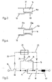
- FIG. 5 An electrical equivalent circuit diagram of this switching device is shown in Fig. 5.
- the first contact point 11 is as a second contact point 19.
- Parallel to the first contact point 11 of the parallel-current path 15 is connected, in which the resistance body 16 is arranged.
- Electrically in series with the resistor body 16 is a not shown in detail in Fig.
- the main current path 18 is another bimetallic strip 36, which is also not shown in FIG. 1; This bimetallic also acts on the switching mechanism 21, wherein the switching mechanism 21 is connected via the line of action 23 with the contact point 19.
- the lines of action of the thermostatic bimetal 20, 36 on the switch lock are designated by the reference numerals 24 and 25.
- the housing 10 is here formed of a cup-shaped housing lower part 10 a and a cup-shaped upper part 10 b, on which respective strips 26, 27; 28, 29 are formed, which are also visible in FIG. 1. Through the strips 26 to 29, a space 30 is formed, in which the resistance body 16 is housed.
- the conductor 31 is designed as a straight component, whereas the conductor 32 in the region of the contacting surface 16 a of the resistance body 16 has a contact surface 16 a convex portion 33.
- At least one of the two conductor pieces 31, 32 is resilient. In the embodiment of FIG. 3, this is the conductor 32, whereas in the embodiment of FIG. 4, the conductor 31 a is formed resiliently.
- the conductor 32 may be shaped so that it holds the resistance body 16 with a bend 34 and a bend or angling 35.
- the resistor body 16 had a positive temperature coefficient, then the current would be limited so far that the armature of the trigger 40 drops and the contact point 11 closes, which would be unfavorable. Due to the approximately constant or negative temperature coefficient, the current through the trigger 40 remains the same or is slightly larger, so that the contact point can be kept sufficiently long in the open position.
- the resistor body may be made of a carbon-doped ceramic; there is also the possibility to use a carbon carbide doped silicon carbide.
- the resistor body 16 may also be doped with other conductive materials.
- the resistance body as needed any shape, eg. B. cylinder, hollow cylinder, cube or prism shape.
Landscapes
- Arc-Extinguishing Devices That Are Switches (AREA)
- Thermally Actuated Switches (AREA)
- Electrical Discharge Machining, Electrochemical Machining, And Combined Machining (AREA)
- Control Of Electric Motors In General (AREA)
- Control Of Motors That Do Not Use Commutators (AREA)
- Saccharide Compounds (AREA)
- Switch Cases, Indication, And Locking (AREA)
- Glass Compositions (AREA)
- Emergency Protection Circuit Devices (AREA)
- Relay Circuits (AREA)
Description
- Die Erfindung betrifft ein elektrisches Schaltgerät, insbesondere einen Hauptleitungsschutzschalter gemäß dem Oberbegriff des Anspruches 1.
- Ein solcher Schalter ist aus der DE 28 54 711 bekannt geworden. Er besitzt eine erste Kontaktstelle, zu der ein Parallelstrompfad geschaltet ist, in dem ein Strombegrenzungswiderstand eingesetzt ist.
- Eine solche Anordnung ist auch in dem Hauptleitungsschutzschalter S 700 der Firma ABB Stotz-Kontakt GmbH Heidelberg verwirklicht. Der Widerstand dort ist als Widerstandsdraht zum Beispiel aus CrAl255, Cu oder aus anderen Legierungen hergestellt, wobei der Draht zu einer Spule gewickelt ist, die aufgrund ihrer Bauform und des geforderten Widerstandswertes einen relativ großen Bauraum beansprucht. Darüber hinaus erzeugt ein solcher spulenförmiger Widerstand ein großes Magnetfeld, so daß die Spule aufwendig antiparallel gewickelt werden muß. Beim Einsatz von blanken Drähten muß die Spule auf einen hochtemperaturbeständigen Trägerkörper gewickelt werden, um zu verhindern, daß sich die Windungen bei Strombeaufschlagung anziehen und somit einen Windungsschluß verursachen. Wenn der Widerstandsdraht isoliert ist, dann kommen als Isolierelemente teure und schlecht handhabbare Materialien, wie z. B. Glasseide zum Einsatz.
- Aufgabe der Erfindung ist es, einen Schalter der Eingangs genannten Art zu schaffen, bei dem die Nachteile der bekannten Anordnung vermieden sind.
- Diese Aufgabe wird erfindungsgemäß durch die Merkmale des Anspruches 1 gelöst.
- Erfindungsgemäß also befindet sich in dem parallel zur ersten Kontaktstelle liegenden Parallelstrompfad ein Widerstandskörper, der aus dotierter Keramik besteht, deren Temperaturkoefizient gleich oder negativ ist.
- Dadurch wird die Verwendung eines Widerstandsdrahtes in Form einer Spule mit all den Nachteilen vermieden und der Widerstandskörper benötigt auch geringeren Platz innerhalb des Schaltgerätes.
- Das Widerstandsmaterial zur Bildung des Widerstandskörpers ist im Handel erhältlich. Es besteht aus einer Mischung von Ton, Aluminium und Kohlenstoff, das nach Zusammenpressen auf seine Endform einem Sinterverfahren unterworfen ist.
- Wenn der Leitungsschutzschalter mit einem aus zwei Schalenhälften zusammengesetzten Gehäuse versehen ist, besitzen die Schalenhälften senkrecht zur Innenfläche der Breitseite verlaufende Leisten, die nach Zusammenbau der Schalenhälften einen Raum begrenzen, in dem der Widerstandskörper aufgenommen und gehaltert ist.
- Zur Kontaktierung wird in bevorzugter Weise eine Federkontaktierung vorgesehen.
- Weitere vorteilhafte Ausgestaltungen und Verbesserungen der Erfindung sind den weiteren Unteransprüchen zu entnehmen.
- Anhand der Zeichnung, in der ein Ausführungsbeispiel der Erfindung dargestellt ist, sollen die Erfindung sowie weitere vorteilhafte Ausgestaltungen und Verbesserungen und weitere Vorteile näher erläutert und beschrieben werden.
- Es zeigen:
- Fig.1
- eine Einsicht in einen elektrischen Leitungsschutzschalter,
- Fig. 2
- eine Schnittansicht gemäß Schnittlinie II- II,
- Fig. 3 und 4
- zwei Alternativen der Kontaktierung eines Widerstandskörpers, und
- Fig. 5
- das elektrische Schaltbild des Schaltgerätes.
- Ein Leitungsschutzschalter besitzt ein Gehäuse 10, das entweder aus einem schalenförmigen Gehäuseunterteil und einem Deckel oder aus zwei etwa gleichen Schalenhälften gebildet sein kann. Innerhalb dieses Gehäuses 10 befindet sich eine erste Kontaktstelle 11 mit einem feststehenden Kontaktstück 12 und einem beweglichen Kontaktstück 13; das bewegliche Kontaktstück 13, das an einem schwenkbaren Kontakthebel 14 angeordnet ist, wird von einem Elektromagneten bei Auftreten eines Kurzschlußstromes verschwenkt, so daß die Kontaktstelle 11 geöffnet wird. Dieser Kontaktstelle 11 ist ein Parallelstrompfad 15 zugeordnet, in dem sich ein Widerstandskörper 16 befindet; wenn die Kontaktstelle 11 geöffnet wird, entsteht dort ein Lichtbogen, der in ein Lichtbogenlöschblechpaket 17 wandert; darüber hinaus wird der Strom in den Nebenstrompfad 15 kommutiert und durch den elektrischen Widerstand des Widerstandskörpers 16 begrenzt.
- Ein elektrisches Ersatzschaltbild dieses Schaltgerätes ist in Fig. 5 dargestellt. In einem Hauptstrompfad 18 befindet sich die erste Kontaktstelle 11 so wie ein zweite Kontaktstelle 19. Parallel zu der ersten Kontaktstelle 11 ist der Parallelstrompfad 15 geschaltet, in dem der Widerstandskörper 16 angeordnet ist. Elektrisch in Reihe zu dem Widerstandskörper 16 befindet sich ein in der Fig. 1 nicht näher dargestelltes Selektivthermobimetall 20, welches auf ein Schaltschloß 21 wirkt, das in der Fig. 1 gezeigt ist und an dem ein Schaltknebel 22 angeordnet bzw. angelenkt ist. Im Hauptstrompfad 18 befindet sich ein weiteres Thermobimetall 36, das in der Fig. 1 ebenfalls nicht dargestellt ist; dieses Thermobimetall wirkt ebenfalls auf das Schaltschloß 21, wobei das Schaltschloß 21 über die Wirklinie 23 mit der Kontaktstelle 19 verbunden ist.
- Die Wirklinien der Thermobimetalle 20, 36 auf das Schaltschloß sind mit den Bezugsziffern 24 und 25 bezeichnet.
- Die Fig. 2 zeigt eine Schnittansicht gemäß Schnittlinie II- II. Das Gehäuse 10 ist hier aus einem schalenförmigen Gehäuseunterteil 10 a und einem schalenförmigen Oberteil 10 b gebildet, an denen jeweils Leisten 26, 27; 28, 29 angeformt sind, die in der Fig. 1 ebenfalls ersichtlich sind. Durch die Leisten 26 bis 29 wird ein Raum 30 gebildet, in dem der Widerstandskörper 16 untergebracht ist.
- Die Kontaktierung des Widerstandskörpers 16 erfolgt mittels Flachbandleitern 31 und 32, die den Parallelstrompfad bilden und in den Fig. 3 und 4 näher dargestellt sind.
- Bei der Ausführung gemäß Fig. 3 ist der Leiter 31 als gerades Bauteil ausgebildet, wogegen der Leiter 32 im Bereich der Kontaktierungsfläche 16 a des Widerstandskörpers 16 einen zur Kontaktierungsfläche 16 a konvexen Abschnitt 33 aufweist.
- Bei der Ausführung gemäß Fig. 4 ist anstatt des geradlinig ausgebildeten Leiters 31 ein solcher 31 a verwendet, der einen zur Kontaktierungsfläche 16 b des Widerstandskörpers 16 hin konvexen Abschnitt 33 a aufweist.
- Wenigstens einer der beiden Leiterstücke 31, 32 ist federnd. Bei der Ausführung gemäß Fig. 3 ist dies der Leiter 32, wogegen bei der Ausführung gemäß Fig. 4 auch der Leiter 31 a federnd ausgebildet ist.
- Wie aus Fig. 1 ersichtlich ist, kann der Leiter 32 so geformt sein, daß er mit einer Abkröpfung 34 und einer Abkantung bzw. Abwinkelung 35 den Widerstandskörper 16 festhält.
- Das hierbei verwendete Material, das oben angegeben ist, besitzt einen Themperaturkoefizienten, der etwa konstant bzw. geringfügig negativ ist. Der Grund liegt in folgendem:
- Wenn der Schalter gemäß Fig. 5 einen Kurzschluß abschalten soll, dann wird über einen magnetischen Auslöser 40 zunächst die Kontaktstelle 11 geöffnet, und zwar über die Wirklinie 41. Dabei wird dann der Strom in den Parallelstrompfad komutiert und durch den Widerstandskörper 16 begrenzt, wobei die Kontaktstelle 19 noch geschlossen ist. Der durch den Widerstand 16 begrenzte Strom durchfließt die Spule 40 und
- hält damit die Kontaktstelle 11 offen. Wenn nun in einem nachgeordneten Leitungsschutzschalter der Kurzschluß abgeschaltet wird, dann schließt die Kontaktstelle 11; wenn der Strom nicht abgeschaltet wird, erwärmt sich das Thermobimetall 20 bzw. 22 und schaltet auf diese Weise die Kontaktstelle 19 endgültig ab. Es wird in diesem Zusammenhang auf die eingangs erwähnte DE 28 54 711 und auf den eingangs erwähnten Schalter S 700 verwiesen.
- Wenn nun der Widerstandskörper 16 einen positiven Temperaturkoefizienten hätte, dann würde der Strom soweit begrenzt, daß der Anker des Auslösers 40 abfällt und die Kontaktstelle 11 schließt, was ungünstig wäre. Aufgrund des etwa konstanten bzw. negativen Temperaturkoefizienten bleibt der Strom durch den Auslöser 40 gleich bzw. wird geringfügig größer, wodurch die Kontaktstelle ausreichend lange in Öffnungsstellung gehalten werden kann.
- Es ist erwähnt worden, daß der Widerstandskörper aus einer mit Kohlenstoff dotierten Keramik bestehen kann; es gibt auch die Möglichkeit, ein mit Kohlenstoff dotiertes Siliziumkarbit zu verwenden. Des weiteren kann der Widerstandskörper 16 auch mit anderen leitfähigen Materialien dotiert sein. Außerdem kann der Widerstandskörper je nach Bedarf jede beliebige Form, z. B. Zylinder-, Hohlzylinder-, Würfel- oder Prismaform aufweisen.
- Es sei noch ergänzt, daß dann, wenn die Stirnseiten des Widerstandkörpers 16 metallisiert sind, die Leitungsstücke 31 und 32 direkt aufgelötet werden können.
Claims (5)
- Elektrisches Schaltgerät mit einer ersten Kontaktstelle (11), die bei einem Kurzschluß von einem elektromagnetischen Aktor in Offenstellung bewegt wird, und mit einer mit der ersten Kontaktstelle in Reihe liegenden zweiten Kontaktstelle (19), die von einem ersten thermischen Auslöser über ein Schaltschloß bleibend geöffnet wird, und mit einem parallel zur ersten Kontaktstelle (11) angeordneten Parallelstrompfad (15), in dem ein strombegrenzender Widerstand (16) untergebracht ist, dadurch gekennzeichnet, daß der Strombegrenzungswiderstand (16) als Widerstandskörper ausgebildet ist, der aus dotiertem Keramikmaterial besteht, dessen Temperaturkoefizient gleich oder negativ ist.
- Elektrisches Schaltgerät nach Anspruch 1, dadurch gekennzeichnet, daß auf der Innenfläche der Breitseite des Gehäuses senkrecht zur Innenfläche verlaufende Leisten angeformt sind, die nach Zusammenbau des Gehäuses einen Raum begrenzen, in dem der Widerstandskörper aufgenommen und gehaltert ist.
- Schaltgerät nach einem der vorigen Ansprüche, dadurch gekennzeichnet, daß wenigstens ein Leiterteilstück, mit dem der Widerstandskörper (16) in den Parallelstrompfad (15) eingeschaltet ist, federnd gegen den Widerstandskörper drückt.
- Schaltgerät nach einem der Ansprüche 1 bis 3, dadurch gekennzeichnet, daß bei Ausführung des Widerstandskörpers (16) mit metallischen Stirnflächen die Leiterteilstücke an den Stirnflächen angelötet sind.
- Schaltgerät nach einem der vorigen Ansprüche, dadurch gekennzeichnet, daß der Widerstandskörper (16) zylindrisch, hohlzylindrisch; würfel- oder prismenförmig und dergleichen ausgebildet ist.
Applications Claiming Priority (3)
| Application Number | Priority Date | Filing Date | Title |
|---|---|---|---|
| DE10203443 | 2002-01-30 | ||
| DE10203443A DE10203443A1 (de) | 2002-01-30 | 2002-01-30 | Elektrisches Schaltgerät |
| PCT/EP2003/000121 WO2003065398A1 (de) | 2002-01-30 | 2003-01-09 | Elektrisches schaltgerät |
Publications (2)
| Publication Number | Publication Date |
|---|---|
| EP1470565A1 EP1470565A1 (de) | 2004-10-27 |
| EP1470565B1 true EP1470565B1 (de) | 2006-04-12 |
Family
ID=7713329
Family Applications (1)
| Application Number | Title | Priority Date | Filing Date |
|---|---|---|---|
| EP03702406A Expired - Lifetime EP1470565B1 (de) | 2002-01-30 | 2003-01-09 | Elektrisches schaltgerät |
Country Status (6)
| Country | Link |
|---|---|
| EP (1) | EP1470565B1 (de) |
| CN (1) | CN1327465C (de) |
| AT (1) | ATE323324T1 (de) |
| DE (3) | DE10261994A1 (de) |
| PL (1) | PL200064B1 (de) |
| WO (1) | WO2003065398A1 (de) |
Families Citing this family (14)
| Publication number | Priority date | Publication date | Assignee | Title |
|---|---|---|---|---|
| DE10354505B4 (de) * | 2003-11-21 | 2006-01-12 | Eti Elektroelement D.D. | Elektrischer Selbstschalter |
| DE102004019178A1 (de) * | 2004-04-16 | 2005-11-03 | Abb Patent Gmbh | Installationsschaltgerät |
| DE102004019175A1 (de) * | 2004-04-16 | 2005-11-03 | Abb Patent Gmbh | Installationsschaltgerät |
| DE102006037234A1 (de) * | 2006-08-09 | 2008-02-14 | Siemens Ag | Schalt-Einheit |
| DE102007004092A1 (de) | 2007-01-26 | 2008-08-07 | Siemens Ag | Leitungsschutzschalter |
| EP1981055A1 (de) | 2007-04-13 | 2008-10-15 | Abb Ag | Installationsschalter und Stromzählersystem |
| DE102008017932A1 (de) | 2007-04-13 | 2008-10-16 | Abb Ag | Installationsschalter und Stromzählersystem |
| SI2223321T1 (sl) * | 2007-12-24 | 2015-10-30 | Eti Elektroelement D.D. | Električno avtomatsko stikalo |
| DE102008017273B4 (de) | 2008-04-04 | 2024-12-12 | Eti Elektroelement D.D. | Elektrischer Selbstschalter |
| DE102008038244B4 (de) | 2008-08-18 | 2016-09-29 | Hager Electro S.A.S. | Selektivauslöser für Hauptsicherungsautomat |
| DE102009036227B4 (de) * | 2009-08-05 | 2015-02-05 | Abb Ag | Elektrischer Widerstand, Verfahren zu seiner Herstellung und Installationsschaltgerät mit elektrischem Widerstand |
| DE102011008078A1 (de) | 2011-01-08 | 2012-07-12 | Peter Flohr | Fernschaltbarer selektiver Hauptleitungsschutzschalter |
| DE102012023914A1 (de) | 2012-12-06 | 2014-06-12 | Peter Flohr | Zentral sperr-und freischaltbarer Hauptsicherungsautomat |
| DE102014001997B4 (de) | 2014-02-17 | 2020-01-09 | Abb Ag | Hilfsschalter mit Test-Taste |
Family Cites Families (9)
| Publication number | Priority date | Publication date | Assignee | Title |
|---|---|---|---|---|
| NL186333B (nl) * | 1945-08-07 | Perm Vnii Burovoj Tekhn | Reductie-overbrenging van een boormotor. | |
| DE947813C (de) * | 1952-11-13 | 1956-08-23 | Licentia Gmbh | Schmelzsicherung zur Ausloesung von Schaltern |
| DE2854616C2 (de) * | 1978-12-18 | 1984-03-22 | Brown, Boveri & Cie Ag, 6800 Mannheim | Selektivschutzeinrichtung |
| DE2854711C2 (de) * | 1978-12-18 | 1984-04-26 | Brown, Boveri & Cie Ag, 6800 Mannheim | Selektivschutzeinrichtung |
| DE3021867A1 (de) * | 1980-06-11 | 1981-12-17 | Brown, Boveri & Cie Ag, 6800 Mannheim | Selbstschalter |
| DE4221309A1 (de) * | 1992-06-29 | 1994-01-05 | Abb Research Ltd | Strombegrenzendes Element |
| DE19500125A1 (de) * | 1995-01-04 | 1996-07-11 | Licentia Gmbh | Strombegrenzer |
| DE19651298C2 (de) * | 1996-12-10 | 1999-04-01 | Fein C & E | Reihenschlußmotor mit Kommutator und Bremswicklung |
| DE29918351U1 (de) * | 1999-10-18 | 2000-02-10 | Chern, Der-Luh, Chung-Ho, Taipeh | Vorrichtung zum Schutz gegen Blitzschlag für ein elektrisches Gerät |
-
2002
- 2002-01-30 DE DE10261994A patent/DE10261994A1/de not_active Withdrawn
- 2002-01-30 DE DE10203443A patent/DE10203443A1/de not_active Withdrawn
-
2003
- 2003-01-09 WO PCT/EP2003/000121 patent/WO2003065398A1/de not_active Ceased
- 2003-01-09 DE DE50302958T patent/DE50302958D1/de not_active Expired - Lifetime
- 2003-01-09 EP EP03702406A patent/EP1470565B1/de not_active Expired - Lifetime
- 2003-01-09 AT AT03702406T patent/ATE323324T1/de not_active IP Right Cessation
- 2003-01-09 CN CNB038007525A patent/CN1327465C/zh not_active Expired - Fee Related
- 2003-01-09 PL PL369824A patent/PL200064B1/pl not_active IP Right Cessation
Also Published As
| Publication number | Publication date |
|---|---|
| EP1470565A1 (de) | 2004-10-27 |
| ATE323324T1 (de) | 2006-04-15 |
| DE10203443A1 (de) | 2003-07-31 |
| PL369824A1 (en) | 2005-05-02 |
| PL200064B1 (pl) | 2008-12-31 |
| DE10261994A1 (de) | 2004-02-05 |
| WO2003065398A1 (de) | 2003-08-07 |
| CN1327465C (zh) | 2007-07-18 |
| DE50302958D1 (de) | 2006-05-24 |
| CN1537316A (zh) | 2004-10-13 |
Similar Documents
| Publication | Publication Date | Title |
|---|---|---|
| DE2809754C2 (de) | Zweipoliger Schutzschalter | |
| EP2697812B1 (de) | Kontakteinrichtung und deren antrieb für schutzschaltgeräte | |
| WO2003065398A1 (de) | Elektrisches schaltgerät | |
| EP0225490B1 (de) | Temperaturbegrenzer | |
| DE102018204104A1 (de) | Schalteinheit zur Trennung eines Stromkreises und Schutzschalter | |
| WO2009114890A1 (de) | Auslösemodul für ein schaltgerät | |
| EP0147681B1 (de) | Polarisiertes elektromagnetisches Relais | |
| DE4406670C2 (de) | Leitungsschutzschalter | |
| DE69202661T2 (de) | Elektrisches bistabiles Relais. | |
| DE1924701A1 (de) | Thermisch ansprechender Schnappschalter | |
| DE60005785T2 (de) | Selbstschalter mit elektromagnetischer Betätigung bei Kurzschluss | |
| DE3338799A1 (de) | Thermischer ausloeser | |
| EP2197010B1 (de) | Schaltersicherungsanordnung für Sammelschienensysteme | |
| EP2284860A2 (de) | Elektrischer Widerstand und Installationsschaltgerät mit elektrischem Widerstand | |
| DE19516723C2 (de) | Thermo-magnetische Auslöseeinrichtung | |
| DE69030666T2 (de) | Ausschalter | |
| DE3882601T2 (de) | Magnetothermische ausloeseeinheit fuer lastschalter oder differentiallastschalter. | |
| DE102019117804B4 (de) | Schalteinrichtung mit einem elektrischen Kontaktsystem | |
| DE2513494C2 (de) | Temperaturschutzschalter für Rohrheizkörper | |
| DE69319271T2 (de) | Selbstschalter | |
| DE2814070C2 (de) | Niederspannungs-Leistungsschalter mit einem Isolierstoffgehäuse und einem Hilfsschalter | |
| DE60000200T2 (de) | Magnetische Baugruppe für ein elektrisches Gerät mit einer begrenzten Breite | |
| DE19815153C1 (de) | Stromwandler zur Versorgung eines elektronischen Überstromauslösers mit Hilfsenergie | |
| DE102012018456A1 (de) | Bimetallanordnung für selektive Schutzschaltgeräte | |
| DE102023135467A1 (de) | Schutzschalter zum Unterbrechen eines Stroms eines elektrischen Verbrauchers |
Legal Events
| Date | Code | Title | Description |
|---|---|---|---|
| PUAI | Public reference made under article 153(3) epc to a published international application that has entered the european phase |
Free format text: ORIGINAL CODE: 0009012 |
|
| 17P | Request for examination filed |
Effective date: 20031202 |
|
| AK | Designated contracting states |
Kind code of ref document: A1 Designated state(s): AT BE BG CH CY CZ DE DK EE ES FI FR GB GR HU IE IT LI LU MC NL PT SE SI SK TR |
|
| GRAP | Despatch of communication of intention to grant a patent |
Free format text: ORIGINAL CODE: EPIDOSNIGR1 |
|
| GRAS | Grant fee paid |
Free format text: ORIGINAL CODE: EPIDOSNIGR3 |
|
| GRAA | (expected) grant |
Free format text: ORIGINAL CODE: 0009210 |
|
| AK | Designated contracting states |
Kind code of ref document: B1 Designated state(s): AT BE BG CH CY CZ DE DK EE ES FI FR GB GR HU IE IT LI LU MC NL PT SE SI SK TR |
|
| PG25 | Lapsed in a contracting state [announced via postgrant information from national office to epo] |
Ref country code: IT Free format text: LAPSE BECAUSE OF FAILURE TO SUBMIT A TRANSLATION OF THE DESCRIPTION OR TO PAY THE FEE WITHIN THE PRESCRIBED TIME-LIMIT;WARNING: LAPSES OF ITALIAN PATENTS WITH EFFECTIVE DATE BEFORE 2007 MAY HAVE OCCURRED AT ANY TIME BEFORE 2007. THE CORRECT EFFECTIVE DATE MAY BE DIFFERENT FROM THE ONE RECORDED. Effective date: 20060412 Ref country code: SI Free format text: LAPSE BECAUSE OF FAILURE TO SUBMIT A TRANSLATION OF THE DESCRIPTION OR TO PAY THE FEE WITHIN THE PRESCRIBED TIME-LIMIT Effective date: 20060412 Ref country code: FI Free format text: LAPSE BECAUSE OF FAILURE TO SUBMIT A TRANSLATION OF THE DESCRIPTION OR TO PAY THE FEE WITHIN THE PRESCRIBED TIME-LIMIT Effective date: 20060412 Ref country code: SK Free format text: LAPSE BECAUSE OF FAILURE TO SUBMIT A TRANSLATION OF THE DESCRIPTION OR TO PAY THE FEE WITHIN THE PRESCRIBED TIME-LIMIT Effective date: 20060412 Ref country code: IE Free format text: LAPSE BECAUSE OF FAILURE TO SUBMIT A TRANSLATION OF THE DESCRIPTION OR TO PAY THE FEE WITHIN THE PRESCRIBED TIME-LIMIT Effective date: 20060412 Ref country code: NL Free format text: LAPSE BECAUSE OF FAILURE TO SUBMIT A TRANSLATION OF THE DESCRIPTION OR TO PAY THE FEE WITHIN THE PRESCRIBED TIME-LIMIT Effective date: 20060412 Ref country code: CZ Free format text: LAPSE BECAUSE OF FAILURE TO SUBMIT A TRANSLATION OF THE DESCRIPTION OR TO PAY THE FEE WITHIN THE PRESCRIBED TIME-LIMIT Effective date: 20060412 Ref country code: GB Free format text: LAPSE BECAUSE OF FAILURE TO SUBMIT A TRANSLATION OF THE DESCRIPTION OR TO PAY THE FEE WITHIN THE PRESCRIBED TIME-LIMIT Effective date: 20060412 |
|
| REG | Reference to a national code |
Ref country code: GB Ref legal event code: FG4D Free format text: NOT ENGLISH |
|
| REG | Reference to a national code |
Ref country code: CH Ref legal event code: EP |
|
| REF | Corresponds to: |
Ref document number: 50302958 Country of ref document: DE Date of ref document: 20060524 Kind code of ref document: P |
|
| REG | Reference to a national code |
Ref country code: IE Ref legal event code: FG4D Free format text: LANGUAGE OF EP DOCUMENT: GERMAN |
|
| PG25 | Lapsed in a contracting state [announced via postgrant information from national office to epo] |
Ref country code: SE Free format text: LAPSE BECAUSE OF FAILURE TO SUBMIT A TRANSLATION OF THE DESCRIPTION OR TO PAY THE FEE WITHIN THE PRESCRIBED TIME-LIMIT Effective date: 20060712 Ref country code: DK Free format text: LAPSE BECAUSE OF FAILURE TO SUBMIT A TRANSLATION OF THE DESCRIPTION OR TO PAY THE FEE WITHIN THE PRESCRIBED TIME-LIMIT Effective date: 20060712 |
|
| PG25 | Lapsed in a contracting state [announced via postgrant information from national office to epo] |
Ref country code: ES Free format text: LAPSE BECAUSE OF FAILURE TO SUBMIT A TRANSLATION OF THE DESCRIPTION OR TO PAY THE FEE WITHIN THE PRESCRIBED TIME-LIMIT Effective date: 20060723 |
|
| PG25 | Lapsed in a contracting state [announced via postgrant information from national office to epo] |
Ref country code: PT Free format text: LAPSE BECAUSE OF FAILURE TO SUBMIT A TRANSLATION OF THE DESCRIPTION OR TO PAY THE FEE WITHIN THE PRESCRIBED TIME-LIMIT Effective date: 20060912 |
|
| NLV1 | Nl: lapsed or annulled due to failure to fulfill the requirements of art. 29p and 29m of the patents act | ||
| ET | Fr: translation filed | ||
| GBV | Gb: ep patent (uk) treated as always having been void in accordance with gb section 77(7)/1977 [no translation filed] |
Effective date: 20060412 |
|
| REG | Reference to a national code |
Ref country code: IE Ref legal event code: FD4D |
|
| PG25 | Lapsed in a contracting state [announced via postgrant information from national office to epo] |
Ref country code: LI Free format text: LAPSE BECAUSE OF NON-PAYMENT OF DUE FEES Effective date: 20070131 Ref country code: MC Free format text: LAPSE BECAUSE OF NON-PAYMENT OF DUE FEES Effective date: 20070131 Ref country code: CH Free format text: LAPSE BECAUSE OF NON-PAYMENT OF DUE FEES Effective date: 20070131 |
|
| PLBE | No opposition filed within time limit |
Free format text: ORIGINAL CODE: 0009261 |
|
| STAA | Information on the status of an ep patent application or granted ep patent |
Free format text: STATUS: NO OPPOSITION FILED WITHIN TIME LIMIT |
|
| 26N | No opposition filed |
Effective date: 20070115 |
|
| REG | Reference to a national code |
Ref country code: CH Ref legal event code: PL |
|
| BERE | Be: lapsed |
Owner name: ABB PATENT G.M.B.H. Effective date: 20070131 |
|
| PG25 | Lapsed in a contracting state [announced via postgrant information from national office to epo] |
Ref country code: BE Free format text: LAPSE BECAUSE OF NON-PAYMENT OF DUE FEES Effective date: 20070131 |
|
| PG25 | Lapsed in a contracting state [announced via postgrant information from national office to epo] |
Ref country code: GR Free format text: LAPSE BECAUSE OF FAILURE TO SUBMIT A TRANSLATION OF THE DESCRIPTION OR TO PAY THE FEE WITHIN THE PRESCRIBED TIME-LIMIT Effective date: 20060713 |
|
| PG25 | Lapsed in a contracting state [announced via postgrant information from national office to epo] |
Ref country code: BG Free format text: LAPSE BECAUSE OF FAILURE TO SUBMIT A TRANSLATION OF THE DESCRIPTION OR TO PAY THE FEE WITHIN THE PRESCRIBED TIME-LIMIT Effective date: 20060712 Ref country code: AT Free format text: LAPSE BECAUSE OF NON-PAYMENT OF DUE FEES Effective date: 20070109 |
|
| PG25 | Lapsed in a contracting state [announced via postgrant information from national office to epo] |
Ref country code: EE Free format text: LAPSE BECAUSE OF FAILURE TO SUBMIT A TRANSLATION OF THE DESCRIPTION OR TO PAY THE FEE WITHIN THE PRESCRIBED TIME-LIMIT Effective date: 20060412 |
|
| PG25 | Lapsed in a contracting state [announced via postgrant information from national office to epo] |
Ref country code: LU Free format text: LAPSE BECAUSE OF NON-PAYMENT OF DUE FEES Effective date: 20070109 Ref country code: CY Free format text: LAPSE BECAUSE OF FAILURE TO SUBMIT A TRANSLATION OF THE DESCRIPTION OR TO PAY THE FEE WITHIN THE PRESCRIBED TIME-LIMIT Effective date: 20060412 |
|
| PGFP | Annual fee paid to national office [announced via postgrant information from national office to epo] |
Ref country code: IT Payment date: 20090127 Year of fee payment: 7 |
|
| PG25 | Lapsed in a contracting state [announced via postgrant information from national office to epo] |
Ref country code: TR Free format text: LAPSE BECAUSE OF FAILURE TO SUBMIT A TRANSLATION OF THE DESCRIPTION OR TO PAY THE FEE WITHIN THE PRESCRIBED TIME-LIMIT Effective date: 20060412 Ref country code: HU Free format text: LAPSE BECAUSE OF FAILURE TO SUBMIT A TRANSLATION OF THE DESCRIPTION OR TO PAY THE FEE WITHIN THE PRESCRIBED TIME-LIMIT Effective date: 20061013 |
|
| PGFP | Annual fee paid to national office [announced via postgrant information from national office to epo] |
Ref country code: FR Payment date: 20090115 Year of fee payment: 7 |
|
| REG | Reference to a national code |
Ref country code: FR Ref legal event code: ST Effective date: 20100930 |
|
| PG25 | Lapsed in a contracting state [announced via postgrant information from national office to epo] |
Ref country code: FR Free format text: LAPSE BECAUSE OF NON-PAYMENT OF DUE FEES Effective date: 20100201 |
|
| PG25 | Lapsed in a contracting state [announced via postgrant information from national office to epo] |
Ref country code: IT Free format text: LAPSE BECAUSE OF NON-PAYMENT OF DUE FEES Effective date: 20100109 |
|
| PGFP | Annual fee paid to national office [announced via postgrant information from national office to epo] |
Ref country code: DE Payment date: 20120123 Year of fee payment: 10 |
|
| PG25 | Lapsed in a contracting state [announced via postgrant information from national office to epo] |
Ref country code: DE Free format text: LAPSE BECAUSE OF NON-PAYMENT OF DUE FEES Effective date: 20130801 |
|
| REG | Reference to a national code |
Ref country code: DE Ref legal event code: R119 Ref document number: 50302958 Country of ref document: DE Effective date: 20130801 |