EP1469624A2 - Veränderung des Anzeigestils eines Gerätes zur Audiosignalverarbeitung aufgrund des Unterschiedes zwischen neuen und alten Parametern - Google Patents
Veränderung des Anzeigestils eines Gerätes zur Audiosignalverarbeitung aufgrund des Unterschiedes zwischen neuen und alten Parametern Download PDFInfo
- Publication number
- EP1469624A2 EP1469624A2 EP04100898A EP04100898A EP1469624A2 EP 1469624 A2 EP1469624 A2 EP 1469624A2 EP 04100898 A EP04100898 A EP 04100898A EP 04100898 A EP04100898 A EP 04100898A EP 1469624 A2 EP1469624 A2 EP 1469624A2
- Authority
- EP
- European Patent Office
- Prior art keywords
- display
- value
- parameter
- signal processing
- loading
- Prior art date
- Legal status (The legal status is an assumption and is not a legal conclusion. Google has not performed a legal analysis and makes no representation as to the accuracy of the status listed.)
- Granted
Links
Images

Classifications
-
- H—ELECTRICITY
- H04—ELECTRIC COMMUNICATION TECHNIQUE
- H04H—BROADCAST COMMUNICATION
- H04H60/00—Arrangements for broadcast applications with a direct linking to broadcast information or broadcast space-time; Broadcast-related systems
- H04H60/02—Arrangements for generating broadcast information; Arrangements for generating broadcast-related information with a direct linking to broadcast information or to broadcast space-time; Arrangements for simultaneous generation of broadcast information and broadcast-related information
- H04H60/04—Studio equipment; Interconnection of studios
Definitions
- the present invention relates to an audio signal processing device which processes audio signals and outputs the audio signals and, more particularly, to an audio signal processing device characterized by control of display on a display portion. Further, the invention relates to a program for making a computer controlling the audio signal processing device perform such a control.
- an indicator is used that presents information by presence or absence of lighting of a light source such as an LED (light emitting diode).
- a light source such as an LED (light emitting diode).
- LED light emitting diode
- a digital mixer described in above described document, it is described that many LEDs are arranged around a dial-type control and used as indicators indicating a value set by the control. In this case, when the value of the parameter is changed by operation of the control, the LEDs are turned on or turned off to indicate a new value after the change.
- the digital mixer including not only a bright place such as the outdoors during the daylight hours but also a dark place such as the inside of a concert hall with the illumination turned off. Even in such a dark place, the set contents of the parameter can be optically easily grasped by providing the aforementioned indicators implemented by the LEDs.
- the display portion in such a conventional digital mixer simply displays the set value of the parameter at the time of performing display.
- This configuration presents no particular problem when the display is performed in accordance with the change in the value of the parameter by the operation using the control. This is because the operator of course grasps what parameter he or she changed, and the changes are performed step by step in this case, so that the operator can easily grasp how the parameter was changed as a whole as well as the current value.
- a known digital mixer including a function of changing only the display to that based on the scene data before the recalled scene data is reflected in the signal processing so as to be able to verify in advance the values of the parameters relating to the scene data.
- several times changes and comparisons between the display of the currently set values of the parameters and the display of the values of the parameters relating to the scene data make it possible for the operator to have some grasp how the parameters will be changed by the recall of the scene data.
- the operation is troublesome and time consuming and, in addition, once the scene data is reflected in the signal processing, the operator needs to remember the changed parts.
- the invention is an audio signal processing device which processes audio signals and outputs the audio signals which comprises: controls for setting values of parameters of the signal processing; a display for presenting a set value of the parameter; a memory for storing a value of the parameter; a loader for loading the value of the parameter stored in the memory; a comparator for comparing, when the loader loads the value of the parameter, a value of the parameter set at a time of the loading with the loaded value of the parameter; and a display controller for making a display style on the display different in accordance with a comparison result on match/mismatch by the comparator.
- the invention is an audio signal processing device which processes audio signals and outputs the audio signals which comprises: controls for setting values of parameters of the signal processing; a display for presenting a set value of the parameter; a memory for storing a value of the parameter; a loader for loading the value of the parameter stored in the memory; and a display controller for making, when the loader loads the value of the parameter, the display simultaneously present the loaded value of the parameter and a value of the parameter set at a time of the loading in different display styles.
- the display is provided with a light source capable of lighting up in a plurality of styles. Further, it is preferable that the light source is a light emitting diode. Further, it is preferable that lighting brightness of the light source is different for each of the display styles. Furthermore, it is preferable that the display is made to present the value of the parameter set at the time of the loading at a lower brightness than the loaded value of the parameter.
- lighting color of the light source is different for each of the display styles.
- the display is a display for presenting continuous values.
- the display is made to present an overlapped part and a different part between the value of the parameter set at the time of the loading and the loaded value of the parameter in different display styles. Further, it is preferable that the display is made to present the overlapped part and the different part using a first display style and a second display style that is less conspicuous than the first display style.
- the display is made to present the overlapped part in the second display style and the different part in the first display style.
- the display is made to present the overlapped part in the first display style and the different part in the second display style.
- the above-described audio signal processing device further comprises an instructor for providing an instruction not to reflect the value of the parameter loaded by the loader in the signal processing, in which when the instruction has been provided by the instructor at the time of the loading of the value of the parameter, the loaded value of the parameter is not reflected in the signal processing.
- the invention is a computer program containing program instructions executable by a computer and causing the computer to execute: a process of processing audio signals and outputting the audio signals; a process of setting values of parameters of the signal processing in accordance with operation of controls; a process of making a display present a set value of the parameter; a process of storing a value of the parameter; a process of loading the value of the parameter stored in the storing; a process of comparing, when loading the value of the parameter in the loading, a value of the parameter set at a time of the loading with the loaded value of the parameter; and a process of making a display style on the display different in accordance with a comparison result on match/mismatch by the comparing.
- the invention is a computer program containing program instructions executable by a computer and causing the computer to execute: a process of processing audio signals and outputting the audio signals; a process of setting values of parameters of the signal processing in accordance with operation of controls; a process of making a display present a set value of the parameter; a process of storing a value of the parameter; a process of loading the value of the parameter stored in the storing; and a process of making, when loading the value of the parameter in the loading, the display simultaneously present the loaded value of the parameter and a value of the parameter set at a time of the loading in different styles.
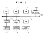
- FIG. 2 is a block diagram showing the configuration of the digital mixer.
- the digital mixer (hereafter, also referred to simply as a “mixer”) is an audio signal processing device which performs various kinds of signal processing such as mixing, equalizing, and so on for inputted audio signals in accordance with set parameters and outputs the audio signals, in which, as shown in FIG. 2, a CPU 111, a ROM 112, a RAM 113, a display circuit 114, a detection circuit 115, a digital signal processor (DSP) 116, and a communication interface (I/F) 120 are connected to a system bus 121. Further, a display 117, controls 118, and an input/output I/F 119 are connected to the display circuit 114, detection circuit 115, DSP116, respectively.
- the CPU 111 is a control unit that comprehensively controls operation of the whole mixer and also executes a predetermined program stored in the ROM 112 to thereby control read and write of data in the ROM 112 and RAM 113, display on the display 117 by the display circuit 114, detection of operation at the controls 118 by the detection circuit 115 and change of values of parameters accompanying the change, signal processing in the DSP 116, communication with external devices via the communication I/F 120, and so on.
- the ROM 112 is a non-volatile memory that stores a control program executed by the CPU 111, and so on.
- the RAM 113 is a memory that includes a later-described setting buffer and verification buffer provided therein to store temporarily necessary data such as values of parameters set in the mixer and is used as a work memory of the CPU 111. Further, a part of the RAM 113 is a rewritable non-volatile memory such as an EEPROM, in which a later-described scene memory is provided to store scene data.
- the display circuit 114 is a circuit that controls display on the display 117 based on control data sent from the CPU 111.
- the configuration of the display 117 will be described later in detail.
- the detection circuit 115 is a circuit that detects operation in the controls 118 based on the control by the CPU 111.
- the configuration of the controls 118 will be described later; the display 117 and the controls 118 can be configured as an integral console panel.
- the DSP 116 is a circuit that performs various kinds of signal processing including mixing and equalizing according to set values of various parameters for audio signals inputted through the input/output I/F 119, and the input/output I/F 119 is an interface for receiving input of audio signals to be processed in the DSP 116 and outputting the processed audio signals.
- the communication I/F 120 is an interface for communicating with an external device such as a personal computer (PC). Further, the mixer can output the audio signals that have been processed by the DSP 116 to the external device, operate in accordance with control by the external device, and download programs from the external device to make the CPU 111 execute the programs.
- an external device such as a personal computer (PC).
- the mixer can output the audio signals that have been processed by the DSP 116 to the external device, operate in accordance with control by the external device, and download programs from the external device to make the CPU 111 execute the programs.
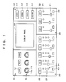
- FIG. 1 A configuration of a console in which the display 117 and controls 118 of the digital mixer are arranged will be described next.
- a configuration example of the console is shown in FIG. 1, in which the configuration is simplified so that only characteristic parts are shown for convenience of illustration, and actually much more controls and display portions are often arranged.
- This console includes, as shown in FIG. 1, a filter operation section 10, a fader operation section 20, a group operation section 30, a scene recall operation section 40, and a display panel 50.
- the filter operation section 10 includes filter controls 11, filter range indicators 12, and filter value display portions 13.
- FIG. 1 shows an example in which three sets of these components are provided.
- the filter control 11 is a dial-type setting control for setting a parameter of the output level of each frequency range by turning to the right with a minimum value at a position of a pointer 11a corresponding to LOW in FIG. 1 and a maximum value at a position of a pointer corresponding to HIGH.
- the filter range indicator 12 is an indicator including a liquid crystal display (LCD), for displaying a frequency range for which the setting of the filter is performed by the filter control 11.
- LCD liquid crystal display
- the filter range indicator 12 on the most left side in FIG. 1 shows that the corresponding filter control 11 is a control for setting the output level of a low frequency range.
- the filter value display portion 13 is a display portion including a light source constituted of an LED capable of lighting-up at a first brightness and a second brightness lower than the first brightness for each of lighting elements that are shown by circles in FIG. 1 to present information of the value of a parameter of the output level set by the corresponding filter control 11 by the presence or absence and the style of the lighting.
- the fader operation section 20 includes fader controls 21, fader channel indicators 22, group setting controls 23, and group display portions 24.
- FIG. 1 shows an example in which five sets of these components are provided.
- the fader control 21 which is a slide-type control, is a setting control for setting the parameter of the input level or the output level of a channel allocated thereto.
- the fader channel indicator 22 is an indicator including an LCD for displaying a channel for which the level is set by the fader control 21.
- the fader channel indicator 22 on the most left side in FIG. 1 shows that the corresponding fader control 21 is a control for setting the input level of a first input ch.
- the group setting control 23 is a setting control for selecting what group or no group the corresponding fader is made to belong to and is designed such that every time the group setting control 23 is pressed, the parameter indicating the group to which the fader will belong changes in sequence and cycles like the group 1 ⁇ 2 ⁇ 3 ⁇ no ⁇ 1.
- the group display portion 24 is a display including, similarly to the filter value display portion 13, an LED for each frame to present information of the value of a parameter set by the corresponding group setting control 23 by the presence or absence and the style of the lighting of the LED.
- the group operation section 30 includes group fader controls 31, group indicators 32, group ON/OFF controls 33, and group ON/OFF display portions 34.
- FIG. 1 shows an example in which three sets of these components are provided.
- the group fader control 31 which is a slide-type control, is a setting control for changing, when a group is effective, the values of parameters set by all the faders belonging to the group all at once by the same amount.
- the group fader 31 does not particularly participate in setting, and therefore the value of the parameter of the fader is set only by the fader control 21 in the fader operation section 20.
- the group indicator 32 is an indicator including an LCD, for displaying a group for which the level is set by the group fader control 31.
- the group indicator 32 on the most left side in FIG. 1 shows that the corresponding group fader control 31 is a control for setting the values of the parameters of a first group.
- the group ON/OFF control 33 is a setting control for setting a parameter of the corresponding group being effective/ineffective and is designed such that every the time group ON/OFF control 33 is pressed, a change is made between ON (effective) and OFF (ineffective) alternately.
- the group ON/OFF display portion 34 is a display portion including, similarly to the filter value display portion 13, an LED to present information of the values of parameters set by the corresponding group ON/OFF control 33 by the presence or absence and the style of the lighting of the LED.
- the scene recall operation section 40 includes scene selection switches 41 to 43 and a preview key 44.
- This mixer stores a set of values of parameters to be reflected in signal processing by the DSP 116 as scene data in a scene memory being a memory.
- the scene selection switches 41 to 43 are switches for instructing recall of the scene data.
- the mixer stores here three kinds of, that is, first to third scene data, and is thus provided with corresponding three scene selection switches to instruct recall of them respectively.
- the CPU 111 loads the corresponding scene data and makes setting so that the values of the parameters included in the scene data are reflected in the signal processing in the DSP 116.
- displays on the display portions 13, 24, and 34 are also changed in accordance with the values of the parameters.
- the preview key 44 is a control for instructing a preview of the scene data.
- the CPU 111 changes only the displays on the display portions 13, 24, and 34 in accordance with the values of the parameters relating to the loaded scene data without reflection of the scene data in the signal processing. Then, the operator can verify the contents of the scene data through the displays. Accordingly, it can be said that the preview key 44 is a control for accepting the selection whether or not the loaded values of the parameters are reflected in the signal processing.
- the display panel 50 which is a display constituted of an LCD, is for displaying a screen for referring to, changing, saving, and so on the setting of the mixer, the operating state of the device, and so on.
- the parameters of the mixer include those set on the screen of the display panel 50 using not-shown controls, in addition to those set by operation of the above-described setting controls.
- the invention is characterized by the style of displays on the display portions 13, 24, and 34, and therefore this point will be described next. Note that a simply mentioned “display portion” in the following description shall represent the display portion including the LEDs.
- the display portion can be made to perform display of the value of the parameter in one of three display styles such as a normal display, a special display A, and a special display B.
- the normal display is a display style in which a current (at the point of display) value of the parameter set by the corresponding control is simply displayed.
- the value of the parameter is changed in accordance with the operation of the control, the value after the change is displayed in the normal display.
- the special display A and special display B are display styles in which when the scene data is recalled, the value of the parameter relating to the recalled scene data (new set value) and the value of the parameter that is set at the time of recalling (old set value) are displayed to show the relation between the values.
- the special display A is a display style showing that the new set value and the old set value match with each other
- the special display B is a display style showing that they do not match with each other.
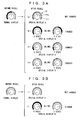
- FIG. 3A to FIG. 5B Specific examples of display in these display styles are shown in FIG. 3A to FIG. 5B.
- FIG. 3A and FIG. 3B show display examples at the filter value display portion 13 of the filter operation section 10
- FIG. 4A and FIG. 4B show display examples at the group display portion 24 of the fader operation section 20
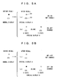
- FIG. 5A and FIG. 5B show display examples at the group ON/OFF display portion 34 of the group operation section 30.
- the lighting elements are shown by black-filled circles, patterned circles, and hollow circles, which represent a state of the LED lighting up at a first brightness, a state lighting up at a second brightness, and a light-out state, respectively.
- the display at the first brightness is a first display style
- the display at the second brightness is a second display style that is less conspicuous than the first display style.
- a plurality of lighting elements are arranged along the movable range of the control (pointer in particular) so that each of the lighting elements corresponds to a value of a parameter where the pointer of the control points the lighting element and near there.
- display is performed by turning on at the first brightness the LEDs starting from the lighting element corresponding to the minimum value to the lighting element corresponding to the current value.
- the filter control 11 is operated clockwise to increase the value, the LEDs light up at the first brightness in sequence toward the right.
- a change is made between an X state and a Y state at a predetermined timing to perform blink display in the two states.
- the X state is a state displaying only the new set value in the above-described normal display, but the state Y is displayed in different methods depending on the magnitude relation between the new set value and the old set value.
- the LEDs from the lighting element corresponding to the minimum value to the lighting element corresponding to the old set value are turned on at the second brightness to thereby display the old set value, and the LEDs therefrom up to the lighting element corresponding to the new set value are turned on at the first brightness to thereby display the new set value.
- the LEDs from the lighting element corresponding to the minimum value to the lighting element corresponding to the new set value are turned on at the first brightness to thereby display the new set value, and the LEDs therefrom up to the lighting element corresponding to the old set value are turned on at the second brightness to thereby display the old set value.
- both cases are the same in that the old set value is displayed by a string of the lighting elements that are turned on at the second brightness and the new set value is displayed by a string of the lighting elements that are turned on at the first brightness.
- the state Y is a display for the recognition but can be confused with the special display A when the new set value is the minimum value, and therefore the state X is also provided and made to blink in order to avoid this confusion. Accordingly, display may be performed only in the state Y in the case where such a situation does not occur. However, the blinking state provides an effect of easily attracting attention to a part where the value of the parameter is changed. It should be noted that in the case shown by the reference symbol (f) in FIG.
- the lighting elements are arranged to correspond to possible values, respectively.
- the LED of the lighting element corresponding to the value of a parameter is turned on at the first brightness, as shown in FIG. 4A, to thereby perform display.
- three lighting elements are provided which are arranged to correspond to a first, a second, and a third group, respectively, from the upper side.
- all the LEDs are turned off as shown in FIG. 4B.
- the same LED of the lighting element as that in the normal display is turned on at the second brightness as shown by a reference symbol (a) in FIG. 4A.
- the lighting element is turned on at the first brightness for ON and is turned off for OFF, as shown in FIG. 5A and FIG. 5B, to thereby perform display in the case of the normal display.
- the display portion is made to perform display in the above-described styles so that when the control is operated to change the value of a parameter, the current value in accordance with the operation can be displayed, while when the stored scene data is loaded, part of the value of a parameter that is changed from the value at the time of the loading and part thereof not changed can be easily distinguished. Further, for the changed part, it is possible to recognize the change in the value of the parameter between before and after the loading.
- the LEDs for the part not changed in the value of the parameter is turned on at the second brightness that is lower than the first brightness, thus making it possible to make this part relatively less conspicuous without a reduction in the amount of information and emphasize the part changed in the value.
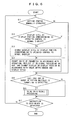
- FIG. 6 is a flowchart showing the processing, but the flowchart shows a characteristic part of the processing related to the embodiment extracted from processing related to detection of the operation in the mixer, setting of parameters, display, and so on. The illustration and description of processing other than this part are omitted.
- Step S1 the operation contents of the control is detected based on a signal from the detection circuit 115. Then, when a manual operation of any of the setting controls is detected, the flow proceeds to Step S2.
- Step S2 it is judged whether or not the display style at the display portion corresponding to the operated setting control is the normal display.
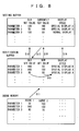
- the set values of each parameter are stored in the setting buffer provided in the RAM 113 as shown in FIG. 8. More specifically, in addition to the current set value that is the value of a parameter that is currently set, the display style at the display portion displaying the value and the old set value that is used for performance of the special displays are also stored in correspondence with each parameter. Therefore, referring to the display style of the parameter corresponding to the operated setting control (the parameter is to be set by the setting control at the time of processing), the display style at the display portion corresponding to the setting control is obtained.
- Step S2 When the result of judgment in Step S2 is not the normal display, the flow proceeds to Step S3, in which the display style at the display portion is changed to the normal display.
- This processing can be performed by changing the display style of the corresponding parameter in the setting buffer to the normal display.
- Step S4 the current value of the parameter stored in the setting buffer is changed in accordance with the operation detected in Step S1 and then reflected in the signal processing in the DSP 116, and the display on the display portion is updated in accordance with the value after the change and the designated display style.
- Step S4 the flow proceeds to Step S5 in which when the scene selection switch is turned on, the scene data recall processing is performed in Step S6, and then the flow proceeds to Step S7. If the switch is not turned on, the flow directly proceeds to Step S7.
- Step S7 when an instruction to stop the mixer, that is, to turn off the power or reboot the mixer is detected in Step S7, the processing is finished, and otherwise the flow returns to Step S1 to repeat the processing.
- Step S2 when the result of judgment in Step S2 is the normal display, the flow proceeds to Step S4 without executing the processing in Step S3, and when no manual operation of the setting control is detected in Step S1, the flow directly proceeds to Step S5.
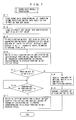
- Step S6 in FIG. 6 is the processing in the flowchart of FIG. 7.
- Step S11 and S12 the scene data corresponding to the turned-on scene selection switch is loaded from the scene memory and stored in the verification buffer as the new set value, and the currently set value of the parameter is loaded from the setting buffer and stored in the verification buffer as the old set value as shown in FIG. 8.
- the CPU 111 functions as a loader.
- the verification buffer here is a buffer into which the values of each parameter is stored in the same form as that in the setting buffer, and is provided to reflect the value of the parameter not in the signal processing in the DSP 116 but only on the display on the display portion so as to enable the operator to verify the contents of the scene data to be loaded.
- Step S13 the old set value and the new set value are compared with each other for each parameter in the verification buffer so that the display style of the parameter is set to the special display A or the special display B in accordance with match/mismatch between the values.
- Step S14 referring and according to the old and new set values and the display style stored in the verification buffer, the display on each display portion is updated in the method shown in FIG. 3A to FIG. 5B.
- the old and new set values of the parameter corresponding to the control corresponding to the display portion are displayed. Since not all the set values of the parameters are displayed, the display style only needs to be determined for at least the parameters to be displayed, in Step S13.
- the CPU 111 functions as a comparator in the above-described processing in Step S13, and functions as a display controller in the processing in Steps S13 and S14.
- Step S16 the CPU 111 waits until the preview key 44 is turned off, and updates the display referring and according to the old and new set values and the display style stored in the setting buffer in Step S17.
- the press is recognized as the setting of not reflecting the loaded scene data in the signal processing being accepted, so that the loaded scene data is used only for display, and upon release of the press, the display is returned to that before the loading, in which no change is made in setting.
- the CPU 111 functions as an instructor in these kinds of processing.
- Step S18 in which the contents of the setting buffer are rewritten with the contents of the verification buffer as shown in FIG. 8, and the new contents of the setting buffer are transmitted to the DSP 116 in Step S19 to be reflected in the signal processing, whereby the processing is completed.
- the new set value in the verification buffer is the current set value in the setting buffer.
- the state is recognized as the setting of reflecting the loaded scene data in the signal processing being accepted, so that the loaded scene data is reflected in the signal processing. Note that it is not particularly necessary to change the display here, but the display thereafter will be performed in accordance with the contents of the setting buffer.
- the DSP 116 automatically refers to the contents of the setting buffer and performs processing based on the contents, the processing in Step S19 is unnecessary.
- the CPU 111 waits and performs no other operation during the press of the preview key 44 is described here, and it is also adoptable to make an arrangement such that the scene selection switches 41 to 43 are pressed one after another while the preview key 44 is being pressed to verify the contents of the scene data. Besides, it is also adoptable to make an arrangement such that when the preview key 44 is released prior to the scene selection switch, the contents of the loaded scene data can be reflected in the signal processing.
- the operability in referring to the contents of a plurality of scene data is improved.
- the operability in reflecting the contents of the scene data in the setting after verification is improved.
- the condition for returning the special display to the normal display the example in which when a control is manually operated, the display style of the display portion corresponding to the control is returned to the normal display has been described, but it is also adoptable to return the display style of all the display portions to the normal display upon operation.
- it is adoptable to make an arrangement such that the display style is returned to the normal display when a predetermined time has elapsed after the recall of the scene data, or when the user presses a specific switch, for example, a switch for changing the display to the normal display, after the recall of the scene data.
- a specific switch for example, a switch for changing the display to the normal display, after the recall of the scene data.
- the contents of the setting data shall be changed and the display on each display portion shall be updated at the point of time when the condition is fulfilled.
- each display portion is not limited to those described using FIG. 3A to FIG. 5B, but any display style is acceptable as long as it is a display style in which when scene data is recalled, part of the value of a parameter that is different before and after the recall and part thereof not changed can be distinguished for recognition.
- display may be performed only in the state X (or the normal display).
- a display style it is preferable to employ a display style such that the values of the parameter before and after the recall are simultaneously presented in different display styles.
- the example in which the LED capable of lighting up at brightness of two levels is used as the light source of the display portion and changed in brightness in accordance with the display contents has been described here, but it is also adoptable to use, for example, a red LED and a green LED in place of the aforementioned LED for a configuration in which each lighting element constituting the display portion can be selectively turned on in red or green so that the color of display is changed in place of brightness.
- the configuration in which the brightness of lighting is changed can make the display easier to view with the lighting element in a simpler configuration.
- the example in which the invention is applied to the digital mixer has been described in the above embodiment, but the invention is not limited to this and is applicable to other audio signal processing devices such as a synthesizer and so on.
- the program for making the components including the CPU 111 realize the above-described functions is stored in the ROM 112 and so on in advance, and the same effect can be obtained also by providing the program recorded on a non-volatile memory such as a CD-ROM or a flexible disc and making the CPU 111 load for execution the program from the memory to the RAM 113, or by making the CPU 111 download for execution from an external device including a recording medium recording the program thereon or an external device storing the program in a memory such as a hard disc drive (HDD).
- HDD hard disc drive
- the display style of a display portion is made different between part of the value of a parameter that is changed from the value at the time of the loading and part thereof not changed, these parts can be easily distinguished.
Applications Claiming Priority (2)
| Application Number | Priority Date | Filing Date | Title |
|---|---|---|---|
| JP2003064096 | 2003-03-10 | ||
| JP2003064096A JP4010261B2 (ja) | 2003-03-10 | 2003-03-10 | 音響信号処理装置及びプログラム |
Publications (3)
| Publication Number | Publication Date |
|---|---|
| EP1469624A2 true EP1469624A2 (de) | 2004-10-20 |
| EP1469624A3 EP1469624A3 (de) | 2005-01-26 |
| EP1469624B1 EP1469624B1 (de) | 2012-06-06 |
Family
ID=32905929
Family Applications (1)
| Application Number | Title | Priority Date | Filing Date |
|---|---|---|---|
| EP04100898A Expired - Fee Related EP1469624B1 (de) | 2003-03-10 | 2004-03-05 | Veränderung des Anzeigestils eines Gerätes zur Audiosignalverarbeitung aufgrund des Unterschiedes zwischen neuen und alten Parametern |
Country Status (4)
| Country | Link |
|---|---|
| US (1) | US7561934B2 (de) |
| EP (1) | EP1469624B1 (de) |
| JP (1) | JP4010261B2 (de) |
| CN (2) | CN1316770C (de) |
Cited By (1)
| Publication number | Priority date | Publication date | Assignee | Title |
|---|---|---|---|---|
| WO2007110576A1 (en) * | 2006-03-28 | 2007-10-04 | Robert Bosch Gmbh | Sound mixing console |
Families Citing this family (22)
| Publication number | Priority date | Publication date | Assignee | Title |
|---|---|---|---|---|
| JP4010261B2 (ja) * | 2003-03-10 | 2007-11-21 | ヤマハ株式会社 | 音響信号処理装置及びプログラム |
| JP4788248B2 (ja) * | 2005-09-07 | 2011-10-05 | セイコーエプソン株式会社 | 画像表示装置、プロジェクタおよび画像表示方法 |
| JP4725255B2 (ja) * | 2005-09-07 | 2011-07-13 | セイコーエプソン株式会社 | 画像表示装置、プロジェクタ、パラメータセット選択方法、及びパラメータセット記憶方法 |
| US20070052733A1 (en) * | 2005-09-07 | 2007-03-08 | Seiko Epson Corporation | Image display device and projector |
| JP4775042B2 (ja) * | 2006-03-09 | 2011-09-21 | ヤマハ株式会社 | 制御装置及びプログラム |
| JP4858821B2 (ja) * | 2006-03-31 | 2012-01-18 | ヤマハ株式会社 | ドットマトリクス表示器を有するディジタルミキサ |
| JP2007295323A (ja) * | 2006-04-26 | 2007-11-08 | Matsushita Electric Ind Co Ltd | 補聴器調整装置 |
| JP2008028778A (ja) * | 2006-07-21 | 2008-02-07 | Sony Corp | 画像処理装置、画像処理方法及びそのプログラム |
| JP4281814B2 (ja) * | 2007-03-07 | 2009-06-17 | ヤマハ株式会社 | コントロール装置 |
| USD609714S1 (en) * | 2007-03-22 | 2010-02-09 | Fujifilm Corporation | Electronic camera |
| JP4582109B2 (ja) * | 2007-04-20 | 2010-11-17 | ヤマハ株式会社 | 音響機器 |
| JP4924402B2 (ja) * | 2007-12-14 | 2012-04-25 | ブラザー工業株式会社 | 制御装置および制御プログラム |
| JP5181838B2 (ja) * | 2008-05-28 | 2013-04-10 | ヤマハ株式会社 | 調節装置およびavアンプ |
| JP5229633B2 (ja) * | 2009-07-13 | 2013-07-03 | ヤマハ株式会社 | ディジタルミキサ |
| JP5288205B2 (ja) * | 2009-08-24 | 2013-09-11 | ヤマハ株式会社 | ネットワークオーディオシステム |
| USD738380S1 (en) * | 2012-12-26 | 2015-09-08 | Ab Initio Technology Llc | Portion of a display screen with a graphical user interface |
| JP6572580B2 (ja) * | 2015-03-24 | 2019-09-11 | ヤマハ株式会社 | 音響信号処理装置及び方法 |
| USD791766S1 (en) * | 2015-11-18 | 2017-07-11 | Haier Us Appliance Solutions, Inc. | Appliance cooktop with interface |
| USD786610S1 (en) * | 2015-11-18 | 2017-05-16 | Haier Us Appliance Solutions, Inc. | Appliance cooktop with interface |
| JP6907577B2 (ja) * | 2017-02-15 | 2021-07-21 | ヤマハ株式会社 | 音処理装置及びパラメータ供給方法 |
| JP7225855B2 (ja) * | 2018-09-13 | 2023-02-21 | ヤマハ株式会社 | 音信号処理装置、音信号処理方法およびプログラム |
| JP7409001B2 (ja) * | 2019-10-25 | 2024-01-09 | ティアック株式会社 | オーディオ装置 |
Citations (3)
| Publication number | Priority date | Publication date | Assignee | Title |
|---|---|---|---|---|
| EP0251646A2 (de) | 1986-06-27 | 1988-01-07 | Amek Systems And Controls Limited | Tonregieanlage |
| WO1991018456A1 (en) | 1990-05-24 | 1991-11-28 | Artemis Technology Limited | Reset system for memorizing and recalling a desired state of a control element |
| US6438241B1 (en) | 1998-02-23 | 2002-08-20 | Euphonix, Inc. | Multiple driver rotary control for audio processors or other uses |
Family Cites Families (12)
| Publication number | Priority date | Publication date | Assignee | Title |
|---|---|---|---|---|
| US4291604A (en) * | 1979-08-01 | 1981-09-29 | Norlin Industries, Inc. | Memory override system for programmed electronic synthesizer |
| US4479240A (en) * | 1981-09-29 | 1984-10-23 | Mckinley Jr Robert H | Audio mixing console with control element position storage |
| AU7461787A (en) * | 1986-06-23 | 1987-12-24 | Loredan Biomedical, Inc. | Muscle capability diagnosis |
| US5243513A (en) * | 1991-04-23 | 1993-09-07 | Peters John M | Automation control with improved operator/system interface |
| WO1993003549A1 (en) * | 1991-07-31 | 1993-02-18 | Euphonix, Inc. | Automated audio mixer |
| US5959610A (en) * | 1993-06-21 | 1999-09-28 | Euphonix | Computer-mirrored panel input device |
| JPH08330865A (ja) * | 1995-05-31 | 1996-12-13 | Sony Corp | 制御情報の表示装置 |
| GB2330753A (en) * | 1997-10-24 | 1999-04-28 | Sony Uk Ltd | Audio processing |
| ATE387702T1 (de) * | 1998-03-20 | 2008-03-15 | Versitech Ltd | Dreifarbiges led-anzeigesystem welches einen audioausgang besitzt |
| JP3656246B2 (ja) * | 2001-04-23 | 2005-06-08 | ヤマハ株式会社 | ディジタル・ミキサ |
| US7489978B2 (en) | 2001-04-23 | 2009-02-10 | Yamaha Corporation | Digital audio mixer with preview of configuration patterns |
| JP4010261B2 (ja) * | 2003-03-10 | 2007-11-21 | ヤマハ株式会社 | 音響信号処理装置及びプログラム |
-
2003
- 2003-03-10 JP JP2003064096A patent/JP4010261B2/ja not_active Expired - Fee Related
-
2004
- 2004-03-05 EP EP04100898A patent/EP1469624B1/de not_active Expired - Fee Related
- 2004-03-08 US US10/796,544 patent/US7561934B2/en not_active Expired - Fee Related
- 2004-03-10 CN CNB2004100283596A patent/CN1316770C/zh not_active Expired - Fee Related
- 2004-03-10 CN CNU2004200064151U patent/CN2684321Y/zh not_active Expired - Fee Related
Patent Citations (3)
| Publication number | Priority date | Publication date | Assignee | Title |
|---|---|---|---|---|
| EP0251646A2 (de) | 1986-06-27 | 1988-01-07 | Amek Systems And Controls Limited | Tonregieanlage |
| WO1991018456A1 (en) | 1990-05-24 | 1991-11-28 | Artemis Technology Limited | Reset system for memorizing and recalling a desired state of a control element |
| US6438241B1 (en) | 1998-02-23 | 2002-08-20 | Euphonix, Inc. | Multiple driver rotary control for audio processors or other uses |
Cited By (2)
| Publication number | Priority date | Publication date | Assignee | Title |
|---|---|---|---|---|
| WO2007110576A1 (en) * | 2006-03-28 | 2007-10-04 | Robert Bosch Gmbh | Sound mixing console |
| US8611562B2 (en) | 2006-03-28 | 2013-12-17 | Red Chip Company Ltd. | Sound mixing console |
Also Published As
| Publication number | Publication date |
|---|---|
| US7561934B2 (en) | 2009-07-14 |
| CN1530898A (zh) | 2004-09-22 |
| JP4010261B2 (ja) | 2007-11-21 |
| EP1469624B1 (de) | 2012-06-06 |
| CN2684321Y (zh) | 2005-03-09 |
| JP2004274512A (ja) | 2004-09-30 |
| US20040179695A1 (en) | 2004-09-16 |
| CN1316770C (zh) | 2007-05-16 |
| EP1469624A3 (de) | 2005-01-26 |
Similar Documents
| Publication | Publication Date | Title |
|---|---|---|
| US7561934B2 (en) | Audio signal processing device | |
| US8005243B2 (en) | Parameter display controller for an acoustic signal processing apparatus | |
| US8519949B2 (en) | Video production switcher panel and related methods | |
| KR100704665B1 (ko) | 디스플레이장치 및 그 제어방법 | |
| JP2013065465A (ja) | 照明操作端末 | |
| US7945060B2 (en) | Parameter display method and program therefor, and parameter setting apparatus | |
| CN111949495A (zh) | 指示灯控制方法、装置、显示设备和可读存储介质 | |
| JP5157990B2 (ja) | Led操作子の輝度調整可能な音響調整卓、及びled操作子の輝度を調整するための操作方法。 | |
| JP2009281691A (ja) | 加熱装置 | |
| JP3979126B2 (ja) | パラメータ設定装置 | |
| US20100217940A1 (en) | Centrifugal separator | |
| JP5830975B2 (ja) | 動作制御装置 | |
| KR200181757Y1 (ko) | 버튼기능을임의로설정할수있는카메라 | |
| JP4101933B2 (ja) | 電子内視鏡装置 | |
| JP4742569B2 (ja) | 調光装置と調光制御用プログラム及び調光装置システム | |
| US20210049991A1 (en) | Loop switcher, controllers therefor and methods for controlling an array of audio effect devices | |
| JP2017026702A (ja) | 表示装置 | |
| JP2010079587A (ja) | 制御パラメータ調整装置および画像表示装置 | |
| TW201443594A (zh) | 智慧型可程序控制裝置 | |
| JPH06309134A (ja) | 表示装置 | |
| JPH09306677A (ja) | 照明制御装置 | |
| JP2005043396A (ja) | パラメータ値表示装置 | |
| JP2007249593A (ja) | プログラマブルコントローラのプログラムモニタ装置 | |
| CN102109558A (zh) | 一种具有可控发光按键的测量设备 | |
| JP2003241162A (ja) | 交換部品を含む装置の使用時間監視装置および液晶プロジェクタ |
Legal Events
| Date | Code | Title | Description |
|---|---|---|---|
| PUAI | Public reference made under article 153(3) epc to a published international application that has entered the european phase |
Free format text: ORIGINAL CODE: 0009012 |
|
| 17P | Request for examination filed |
Effective date: 20040310 |
|
| AK | Designated contracting states |
Kind code of ref document: A2 Designated state(s): AT BE BG CH CY CZ DE DK EE ES FI FR GB GR HU IE IT LI LU MC NL PL PT RO SE SI SK TR |
|
| AX | Request for extension of the european patent |
Extension state: AL LT LV MK |
|
| PUAL | Search report despatched |
Free format text: ORIGINAL CODE: 0009013 |
|
| AK | Designated contracting states |
Kind code of ref document: A3 Designated state(s): AT BE BG CH CY CZ DE DK EE ES FI FR GB GR HU IE IT LI LU MC NL PL PT RO SE SI SK TR |
|
| AX | Request for extension of the european patent |
Extension state: AL LT LV MK |
|
| 17Q | First examination report despatched |
Effective date: 20050301 |
|
| AKX | Designation fees paid |
Designated state(s): DE FR GB IT |
|
| RAP1 | Party data changed (applicant data changed or rights of an application transferred) |
Owner name: YAMAHA CORPORATION |
|
| REG | Reference to a national code |
Ref country code: DE Ref legal event code: R079 Ref document number: 602004038038 Country of ref document: DE Free format text: PREVIOUS MAIN CLASS: H04H0007000000 Ipc: H04H0060040000 |
|
| GRAP | Despatch of communication of intention to grant a patent |
Free format text: ORIGINAL CODE: EPIDOSNIGR1 |
|
| RIC1 | Information provided on ipc code assigned before grant |
Ipc: H04H 60/04 20080101AFI20111115BHEP |
|
| GRAS | Grant fee paid |
Free format text: ORIGINAL CODE: EPIDOSNIGR3 |
|
| GRAA | (expected) grant |
Free format text: ORIGINAL CODE: 0009210 |
|
| AK | Designated contracting states |
Kind code of ref document: B1 Designated state(s): DE FR GB IT |
|
| REG | Reference to a national code |
Ref country code: GB Ref legal event code: FG4D |
|
| REG | Reference to a national code |
Ref country code: DE Ref legal event code: R096 Ref document number: 602004038038 Country of ref document: DE Effective date: 20120802 |
|
| PG25 | Lapsed in a contracting state [announced via postgrant information from national office to epo] |
Ref country code: IT Free format text: LAPSE BECAUSE OF FAILURE TO SUBMIT A TRANSLATION OF THE DESCRIPTION OR TO PAY THE FEE WITHIN THE PRESCRIBED TIME-LIMIT Effective date: 20120606 |
|
| PLBE | No opposition filed within time limit |
Free format text: ORIGINAL CODE: 0009261 |
|
| STAA | Information on the status of an ep patent application or granted ep patent |
Free format text: STATUS: NO OPPOSITION FILED WITHIN TIME LIMIT |
|
| 26N | No opposition filed |
Effective date: 20130307 |
|
| REG | Reference to a national code |
Ref country code: DE Ref legal event code: R097 Ref document number: 602004038038 Country of ref document: DE Effective date: 20130307 |
|
| PGFP | Annual fee paid to national office [announced via postgrant information from national office to epo] |
Ref country code: FR Payment date: 20140311 Year of fee payment: 11 |
|
| PGFP | Annual fee paid to national office [announced via postgrant information from national office to epo] |
Ref country code: GB Payment date: 20140305 Year of fee payment: 11 |
|
| PGFP | Annual fee paid to national office [announced via postgrant information from national office to epo] |
Ref country code: DE Payment date: 20140417 Year of fee payment: 11 |
|
| REG | Reference to a national code |
Ref country code: DE Ref legal event code: R119 Ref document number: 602004038038 Country of ref document: DE |
|
| GBPC | Gb: european patent ceased through non-payment of renewal fee |
Effective date: 20150305 |
|
| REG | Reference to a national code |
Ref country code: FR Ref legal event code: ST Effective date: 20151130 |
|
| PG25 | Lapsed in a contracting state [announced via postgrant information from national office to epo] |
Ref country code: GB Free format text: LAPSE BECAUSE OF NON-PAYMENT OF DUE FEES Effective date: 20150305 Ref country code: DE Free format text: LAPSE BECAUSE OF NON-PAYMENT OF DUE FEES Effective date: 20151001 |
|
| PG25 | Lapsed in a contracting state [announced via postgrant information from national office to epo] |
Ref country code: FR Free format text: LAPSE BECAUSE OF NON-PAYMENT OF DUE FEES Effective date: 20150331 |