EP1468855A2 - Fahrzeugtür - Google Patents
Fahrzeugtür Download PDFInfo
- Publication number
- EP1468855A2 EP1468855A2 EP04008543A EP04008543A EP1468855A2 EP 1468855 A2 EP1468855 A2 EP 1468855A2 EP 04008543 A EP04008543 A EP 04008543A EP 04008543 A EP04008543 A EP 04008543A EP 1468855 A2 EP1468855 A2 EP 1468855A2
- Authority
- EP
- European Patent Office
- Prior art keywords
- vehicle
- door
- frame
- outside
- inner frame
- Prior art date
- Legal status (The legal status is an assumption and is not a legal conclusion. Google has not performed a legal analysis and makes no representation as to the accuracy of the status listed.)
- Withdrawn
Links
- 239000000853 adhesive Substances 0.000 claims description 48
- 230000001070 adhesive effect Effects 0.000 claims description 47
- 238000007789 sealing Methods 0.000 claims description 12
- 229910052751 metal Inorganic materials 0.000 description 24
- 239000002184 metal Substances 0.000 description 24
- 230000002787 reinforcement Effects 0.000 description 17
- 229910000838 Al alloy Inorganic materials 0.000 description 16
- 230000006835 compression Effects 0.000 description 13
- 238000007906 compression Methods 0.000 description 13
- 229910052782 aluminium Inorganic materials 0.000 description 12
- XAGFODPZIPBFFR-UHFFFAOYSA-N aluminium Chemical compound [Al] XAGFODPZIPBFFR-UHFFFAOYSA-N 0.000 description 12
- 239000000463 material Substances 0.000 description 12
- 238000009957 hemming Methods 0.000 description 11
- 241001074085 Scophthalmus aquosus Species 0.000 description 9
- 230000003014 reinforcing effect Effects 0.000 description 8
- 229910000861 Mg alloy Inorganic materials 0.000 description 7
- 239000000446 fuel Substances 0.000 description 6
- 238000003466 welding Methods 0.000 description 6
- FYYHWMGAXLPEAU-UHFFFAOYSA-N Magnesium Chemical compound [Mg] FYYHWMGAXLPEAU-UHFFFAOYSA-N 0.000 description 5
- 238000005452 bending Methods 0.000 description 5
- 229910052749 magnesium Inorganic materials 0.000 description 5
- 239000011777 magnesium Substances 0.000 description 5
- 230000003028 elevating effect Effects 0.000 description 3
- XEEYBQQBJWHFJM-UHFFFAOYSA-N Iron Chemical compound [Fe] XEEYBQQBJWHFJM-UHFFFAOYSA-N 0.000 description 2
- 230000015572 biosynthetic process Effects 0.000 description 2
- 239000013521 mastic Substances 0.000 description 2
- 230000002093 peripheral effect Effects 0.000 description 2
- 230000008961 swelling Effects 0.000 description 2
- 239000004593 Epoxy Substances 0.000 description 1
- 229910000831 Steel Inorganic materials 0.000 description 1
- 238000001125 extrusion Methods 0.000 description 1
- 239000012943 hotmelt Substances 0.000 description 1
- 229910052742 iron Inorganic materials 0.000 description 1
- 238000004064 recycling Methods 0.000 description 1
- 239000010959 steel Substances 0.000 description 1
Images


Classifications
-
- B—PERFORMING OPERATIONS; TRANSPORTING
- B60—VEHICLES IN GENERAL
- B60J—WINDOWS, WINDSCREENS, NON-FIXED ROOFS, DOORS, OR SIMILAR DEVICES FOR VEHICLES; REMOVABLE EXTERNAL PROTECTIVE COVERINGS SPECIALLY ADAPTED FOR VEHICLES
- B60J5/00—Doors
- B60J5/04—Doors arranged at the vehicle sides
- B60J5/042—Reinforcement elements
- B60J5/0422—Elongated type elements, e.g. beams, cables, belts or wires
- B60J5/0423—Elongated type elements, e.g. beams, cables, belts or wires characterised by position in the lower door structure
- B60J5/0426—Elongated type elements, e.g. beams, cables, belts or wires characterised by position in the lower door structure the elements being arranged at the beltline
-
- B—PERFORMING OPERATIONS; TRANSPORTING
- B60—VEHICLES IN GENERAL
- B60J—WINDOWS, WINDSCREENS, NON-FIXED ROOFS, DOORS, OR SIMILAR DEVICES FOR VEHICLES; REMOVABLE EXTERNAL PROTECTIVE COVERINGS SPECIALLY ADAPTED FOR VEHICLES
- B60J5/00—Doors
- B60J5/04—Doors arranged at the vehicle sides
- B60J5/0401—Upper door structure
- B60J5/0405—Inboard or outboard side of window frame formed integrally with the lower door structure
-
- B—PERFORMING OPERATIONS; TRANSPORTING
- B60—VEHICLES IN GENERAL
- B60J—WINDOWS, WINDSCREENS, NON-FIXED ROOFS, DOORS, OR SIMILAR DEVICES FOR VEHICLES; REMOVABLE EXTERNAL PROTECTIVE COVERINGS SPECIALLY ADAPTED FOR VEHICLES
- B60J5/00—Doors
- B60J5/04—Doors arranged at the vehicle sides
- B60J5/0401—Upper door structure
- B60J5/0408—Upper door structure fastening window frame or parts of window frame to lower door structure
-
- B—PERFORMING OPERATIONS; TRANSPORTING
- B60—VEHICLES IN GENERAL
- B60J—WINDOWS, WINDSCREENS, NON-FIXED ROOFS, DOORS, OR SIMILAR DEVICES FOR VEHICLES; REMOVABLE EXTERNAL PROTECTIVE COVERINGS SPECIALLY ADAPTED FOR VEHICLES
- B60J5/00—Doors
- B60J5/04—Doors arranged at the vehicle sides
- B60J5/0412—Lower door structure
-
- B—PERFORMING OPERATIONS; TRANSPORTING
- B60—VEHICLES IN GENERAL
- B60J—WINDOWS, WINDSCREENS, NON-FIXED ROOFS, DOORS, OR SIMILAR DEVICES FOR VEHICLES; REMOVABLE EXTERNAL PROTECTIVE COVERINGS SPECIALLY ADAPTED FOR VEHICLES
- B60J5/00—Doors
- B60J5/04—Doors arranged at the vehicle sides
- B60J5/042—Reinforcement elements
- B60J5/0422—Elongated type elements, e.g. beams, cables, belts or wires
- B60J5/0423—Elongated type elements, e.g. beams, cables, belts or wires characterised by position in the lower door structure
- B60J5/0429—Elongated type elements, e.g. beams, cables, belts or wires characterised by position in the lower door structure the elements being arranged diagonally
Definitions
- the present invention relates to a door for a vehicle, the rigidity of which is high.
- the present invention relates to a door for a vehicle, the rigidity and the buffer action property of which are high.
- This door frame structure includes: a front frame member (a door inner front member) for forming a front edge of the door body; a rear frame member (a door inner rear member) for forming a rear edge of the door body; an upper frame (a waist reinforcing member) for connecting the front frame member with the rear frame member; and a lower frame (a sill extruded member).
- the lower frame (the sill extruded member) in this door frame structure is made by a plate-shaped member made of light metal such as aluminum or magnesium.
- the lower frame in this door frame structure is made by a plate-shaped member of an extruded material of light metal.
- the lower frame (the sill extruded member) is arranged being extended in the longitudinal direction of the vehicle body with respect to the door body.
- JP-A-2001-341529 (Pages 4 and 6, Figs. 1 and 17) Further, concerning the conventional door for a vehicle, the rigidity of which is high, a reinforcing structure of the door for a vehicle is well known, in which an inner frame (an inner reinforcement) extending in the longitudinal direction is arranged in an upper portion of the door body so as to ensure the mechanical strength of an upper portion of the door body. Concerning this reinforcing structure, for example, refer to Patent Document 2.
- This reinforcing structure of the door for a vehicle includes: an outer reinforcement arranged in an upper end portion of the outer door panel; and an inner reinforcement arranged in an upper portion of the inner door panel.
- Each of the outer and the inner reinforcement is a cylindrical member having a closed cross section.
- These outer and the inner reinforcement are made of an extruded material of light metal such as aluminum.
- the inner frame (a waist reinforcing member) of this door frame structure includes an inner waist reinforcement and outer waist reinforcement.
- Each of the inner waist reinforcement and outer waist reinforcement is a substantially cylindrical body, the cross-section of which is hollow, made of an extruded material of light metal such as aluminum.
- the inner reinforcement arranged inside the vehicle described in Patent Document 2 the following problems may be encountered.
- the inner reinforcement has a relatively large cross section. Therefore, the thickness of the entire door is increased.
- the cross section is formed into a closed section having a hollow portion. Therefore, in the case where a passenger bumps against the inner reinforcement and inner waist reinforce when the vehicle comes into a collision with another one, since the inner reinforcement and inner waist reinforcement have a cylindrical hollow portion, it is difficult for the inner reinforcement and inner waist reinforcement to be deformed.
- the inner frame which is arranged in the door body inside the vehicle, is provided with both the rigidity for reinforcing the door body and the buffer action property for protecting the passenger from an impact force generated in a collision.
- a door for a vehicle described in aspect 1 includes: a lower frame arranged in a lower portion of the door body, extending in the longitudinal direction of the vehicle; an outside plate for forming a surface of the vehicle body, arranged outside of the lower frame; and an outer panel having an inside plate folded back at a lower end portion of the outside plate, the inside plate extending to the inside of the vehicle of the lower frame, wherein a closed cross section is formed in a lower portion of the door body when the lower frame and the outer panel are joined to each other.
- a door body includes: a lower frame extending in the longitudinal direction of the vehicle; an outside plate for forming a surface of the vehicle body, arranged outside of the lower frame; and an outer panel having an inside plate folded back at a lower end portion of the outside plate, the inside plate extending to the inside of the vehicle of the lower frame.
- the outside plate and inside plate of this outer panel and the lower frame form a closed cross section in the lower portion of the door body, the lower portion of the door can be reinforced.
- the door body has a portion, the profile of which is a closed cross section, including the lower frame and the outer panel, this portion, the profile of which is the closed cross section, receives a compression load, tensile load and twist load which are given in the vehicle collision. Therefore, the lower portion of the door is provided with a sufficiently high rigidity.
- a door for a vehicle described in aspect 2 includes: a door body including a front frame member arranged on the front side of the vehicle, including a rear frame member arranged on the rear side of the vehicle and including a lower frame for connecting the front frame member with the rear frame member; and an outer panel including an outside plate for forming a surface of the vehicle in the lower frame outside the vehicle and an inside plate folded back at a lower end portion of the outside plate, the inside plate extending to the inside of the vehicle of the lower frame, wherein a closed cross section is formed in a lower portion of the door body when the lower frame and the outer panel are joined to each other.
- a door for a vehicle includes: a door body including a front frame member, including a rear frame member arranged on the rear side of the vehicle and including a lower frame for connecting the front frame member with the rear frame member; and an outer panel including an outside plate for forming a surface of the vehicle in the lower frame outside the vehicle and an inside plate folded back at a lower end portion of the outside plate, the inside plate extending to the inside of the vehicle of the lower frame. Therefore, the door body can have a frame structure. For the above reasons, even when the door body is constituted by members made of aluminum or magnesium, the press-forming property of which is low, the door can be easily made by connecting these members. Due to the foregoing, the door can be made of light metal. Therefore, the weight of the entire vehicle can be reduced and the fuel consumption can be enhanced.
- the lower portion of the door can be reinforced.
- this portion, the profile of which is a closed cross section including the lower frame and the outer panel, this portion, the profile of which is a closed cross section, can receive a compression load, tensile load and twist load which are given in the vehicle collision. Therefore, in the case where the door body forms a frame structure, it is possible to prevent the frame structure from buckling. Accordingly, the door can be reinforced by the portion in which the closed cross section is formed, that is, the rigidity of the door can be enhanced.
- a door for a vehicle according to aspect 3 is the door for a vehicle according to aspect 1 or 2, wherein the lower frame includes an inside flange fixed to the inside plate and an outside flange connected to the outside plate so that the outside flange can be relatively displaced with respect to the outside plate.
- the lower frame includes an outside flange connected to the outside plate so that the outside flange can be relatively displaced with respect to the outside plate. Therefore, the outside flange is not fixed to the outside plate by means of welding or fastening in which a fastening member is used. For the above reasons, it is possible to prevent the formation of a trace of welding or deformation on a face of the outside plate. That is, the face of the outside plate can be beautifully finished.
- a door for a vehicle described in aspect 4 is the door for a vehicle according to aspect 3, wherein the outside flange is connected to the outside plate by an adhesive sealing member.
- the outside flange when the outside flange is connected to the outside plate by an adhesive sealing member, the outside flange can be connected by a simple means so that the outside flange can be displaced with respect to the outside plate. Since the outside flange is connected to the outside plate of the outer panel by the adhesive sealing member, there is no possibility that a face of the outside plate on the outside the vehicle is deformed by the member connected. Therefore, the face of the outside plate outside the vehicle can be beautifully finished.
- a door for a vehicle according to aspect 5 is the door for a vehicle according to one of aspects 1 to 4, wherein the inside flange is formed extending upward along the inside plate.
- the inside flange of the lower frame is formed extending upward along the inside plate, the inside flange is arranged in an upper portion of the closed cross section formed by the lower frame and the outer panel. Therefore, in the case of working in which the inside flange is fixed to the door body, working can be easily conducted since the inside flange is located in the upper portion of the closed cross section.
- the inside flange is arranged being put on the inside plate of the outer panel, the mechanical strength of the portion, in which the inside flange is put on the inside plate of the outer panel, can be enhanced. Therefore, the portion, in which the inside flange is put on the inside plate of the outer panel, can be used as a space in which other parts such as a window regulator are arranged.
- a door for a vehicle according to aspect 6 is the door for a vehicle according to one of aspects 1 to 5, wherein the outer panel is formed by means of press forming.
- the outer panel is formed by means of press-forming. Therefore, the outer panel can be made of material used for press-forming, the mechanical strength of which is high. Accordingly, the rigidity of the closed cross section can be enhanced, and the productivity can be also enhanced.
- a door for a vehicle described in aspect 7 includes: an inner frame arranged in a door body inside the vehicle, extending in the longitudinal direction of the vehicle, wherein the inner frame includes an opening, the cross section of which is a substantial C-shape, extending in the longitudinal direction, and the inner frame is arranged in the door body so that the opening can be directed outside the vehicle.
- inside the vehicle described in aspects is defined as a case in which a member is arranged inside the passenger's room with respect to a portion in which the windowpane is arranged.
- the door body since the door body includes an inner frame extending in the longitudinal direction of the vehicle, the inner frame receives a compression load, tensile load and twist load given to the door body in the collision. Therefore, the rigidity of the door body can be enhanced.
- the inner frame When a passenger bumps against the inner frame inside the vehicle at this time, since the inner frame is provided with an opening and the cross section of the inner frame is formed into a substantial C-shape, the inner frame is relatively liable to be deformed as compared with a case in which the inner frame is formed into a closed section. Therefore, the door body has a buffer action property. Accordingly, it is possible to protect the passenger from an impact force caused in the collision. In this way, the inner frame can be provided with the rigidity, and further the buffer action property of the inner frame can be appropriately enhanced.
- a door for a vehicle described in aspect 8 includes a door body, the door body including: a front frame member arranged on the front side of the vehicle; a rear frame member arranged on the rear side of the vehicle; and an inner frame for connecting the front frame member with the rear frame member inside the vehicle, wherein the inner frame includes an opening, the cross section of which is a substantial C-shape, extending in the longitudinal direction, and the inner frame is arranged in the door body so that the opening can be directed outside the vehicle.
- the door body includes: a front frame member; a rear frame member; and an inner frame for connecting the front frame member with the rear frame member. Therefore, it is possible to form the door body into a frame structure. Accordingly, even when the members are made of material such as aluminum or magnesium, the press-forming property of which is low, the door can be easily made by connecting these members. Due to the foregoing, the door can be made of light metal, and the weight of the entire vehicle can be reduced and the fuel consumption can be enhanced.
- the inner frame receives a compression load, tensile load and twist load given to the door in the collision, and the door body can be prevented from being buckled. Accordingly, the door can be reinforced by the inner frame and the rigidity can be enhanced.
- the inner frame the cross section of which is formed into a substantial C-shape, is arranged in the door body in such a manner that the opening portion of the inner frame is directed outside the vehicle.
- the inner frame is bent, that is, the inner frame is provided with a buffer action property. Therefore, it is possible to protect the passenger from the impact force.
- a door for a vehicle described in aspect 9 is the door for a vehicle according to aspect 7 or 8, wherein the inner frame includes a pair of flanges extending from the upper and the lower portion of the inner frame toward the inside of the opening, and the width of each flange in the vertical direction is set at 1/4 to 1/2 of the width in the vertical direction of the base portion which forms the portion, the cross section of which is formed into a C-shape.
- the inner frame includes a pair of flanges extending toward the inside of the opening, and the width of each flange in the vertical direction is set at 1/4 to 1/2 of the width in the vertical direction of the base portion. Due to the foregoing, a large lateral cross-sectional area of the inner frame can be formed. Therefore, the rigidity can be enhanced. For example, when the vehicle comes into a head-on collision with another one in which an impact force is given to the vehicle in the front portion, since the inner frame is provided with the flange, the rigidity of the inner frame is high. Therefore, even when the inner frame is given a compression load, twist load and tensile load, bending and twisting are seldom caused in the inner frame, that is, the door can be appropriately reinforced.
- a door for a vehicle described in aspect 10 is the door for a vehicle according to one of aspects 7 to 9, wherein the width of the inner frame in the width direction of the vehicle is set at 1/6 to 1/1 of the width in the vertical direction of the base portion which forms the portion, the cross section of which is formed into a C-shape.
- the width of the inner frame in the width direction of the vehicle is set at 1/6 to 1/1 of the width in the vertical direction of the base portion. Therefore, the inner frame can easily receive bending moment. Accordingly, the inner frame can be provided with an appropriately high rigidity and buffer action property. For example, in the case where the vehicle collides with another one and the passenger bumps against the door inside the vehicle, since the inner frame is provided with a width in the width direction of the vehicle, when an impact force in the vehicle width direction, the intensity of which is not less than a predetermined value, is given, these portions having the width in the vehicle width direction are bent being pushed by the passenger, so that the impact force given to the passenger can be reduced. Accordingly, the passenger can be protected from the damage caused by the impact force.
- a door for a vehicle described in aspect 11 is the door for a vehicle according to one of aspects 7 to 10, wherein a connecting portion of connecting a side of the inner frame inside the vehicle with upper and lower leg portions extending from the upper and lower end portions of the side toward the outside of the vehicle is formed being curved.
- the above curved connecting portion forms a curved face, the radius of curvature of which is not less than 5 mm.
- a door for a vehicle described in a first general aspect is the door for a vehicle includes: a door beam; an inner frame having a section of C shape; and a lower frame, extending in a longitudinal direction of the vehicle and forming a closed section with an outer panel.
- a door for a vehicle described in a second general aspect is the door for a vehicle includes: a door beam; an inner frame having a section of C shape; and a lower frame, extending in a longitudinal direction of the vehicle and forming a closed section with an outer panel, wherein a front frame member arranged on the front side of the vehicle and a rear frame member arranged on the rear side of the vehicle are connected by the inner frame and the lower frame.
- door D is of the hinge type or the slide type or the gull-wing type arranged on the right and left or at the rear end portion of the vehicle.
- the type of this door D is not particularly limited.
- door D includes: a door body 1; an outer panel 2 arranged outside the door body 1; a window device 3 arranged in the door body 1, for elevating the windowpane 31; a lining 4 arranged in the door body 1 inside the vehicle; an inside handle 5 arranged on the lining 4; a door lock device 6 for locking and unlocking door D; a speaker 7 arranged in door D; a harness 8 for electrically connecting electric equipment including the speaker 7 arranged in door D and the window device 3; and a rubber frame 9 arranged on the overall circumference of door D.
- Fig. 3 is a view showing the door for a vehicle of the embodiment of the present invention. That is, Fig. 3 is an enlarged perspective view of the door body, wherein the view is taken from the outside of the vehicle.
- Fig. 4 is a view showing the door for a vehicle of the embodiment of the present invention. That is, Fig. 4 is an enlarged perspective view of the door body, wherein the view is taken from the inside of the vehicle.
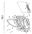
- Fig. 5 is a view showing the door for a vehicle of the embodiment of the present invention. That is, Fig. 5 is an enlarged perspective view of the door body and outer panel, one portion of which is shown by a cross-sectional view.
- the door body 1 is a member forming a frame of door D.
- the door body 1 is made of light metal such as aluminum alloy or magnesium alloy.
- the door body 1 includes: a front frame member 11 arranged on the front side of the vehicle; a rear frame member 12 arranged on the rear side of the vehicle; an upper inner frame 13 for connecting the front frame member 11 with the rear frame member 12, arranged inside the vehicle; an upper outer frame 14 arranged outside the vehicle with respect to the upper inner frame 13; an outside door sash 15 for supporting the windowpane 31 (shown in Fig. 2); a lower frame 16 for connecting the front frame member 11 with the rear frame member 12; a door beam 17 which is a reinforcing member of the door body 1; and hinge members 18, 18 for pivotally attaching the door body 1 to the vehicle body.
- the door body 1 is formed into a profile of projected parallels by the front frame member 11, rear frame member 12, upper and inner frame 13, upper outer frame 14 and lower frame 16.
- the outer panel 2 is stuck to a circumferential edge portion of the frame of the door body 1, the profile of which is formed into projected parallels, by the means of both hemming working and structural adhesive S (shown in Figs. 9 and 10).
- each member constituting the door body 1 will be explained as follows. First, referring to Figs. 3 to 5, the front frame member 11 is explained.
- the front frame member 11 is a member forming a frame on the front side of the door body 1.
- the front frame member 11 is made by an aluminum die-cast product of light metal such as aluminum.
- This front frame member 11 includes: a sash attaching portion 11a to which the outside door sash 15 is fixed; an engaging groove 11b to which the upper inner frame 13 is fixed; a fixing face 11c to which the upper outer frame 14 and the outer panel 2 (shown in Fig.
- the sash attaching portion 11a, engaging groove 11b, fixing face 11c, bracket 19 and upper hinge member 19 are arranged in the upper portion of the front frame member 11.
- the connecting portion 11e and lower hinge member 18 are arranged in the lower end portion of the front frame member 11.
- the outside circumferential portion 11h is arranged in the front end portion and the lower end portion of the front frame member 11.
- the sash attaching portion 11a is a portion in which the front lower end portion 15a of the outside sash 15 is engaged with the upper end portion of the front frame member 11 and stuck by structural adhesive S (shown in Figs. 9 and 10).
- structural adhesive S shown in Figs. 9 and 10
- the cutout portion 11g in which the front lower end portion 15a of the outside door sash 15 is engaged, is formed.
- This sash attaching portion 11a is coated with structural adhesive S. Therefore, the outside door sash 15 is fixed by this structural adhesive S.
- structural adhesive S is an adhesive agent made of epoxy used for the adhesion of aluminum alloy.
- the engaging groove 11b is a substantially U-shaped groove formed in the lower rear portion in the neighborhood of the sash attaching portion 11a described before.
- the front end portion 13a of the upper inner frame 13 is engaged and stuck in this engaging groove 11b by structural adhesive S. Further, the front end portion 13a of the upper inner frame 13 is also stuck in this engaging groove 11b by means of riveting.
- the fixing face 11c is a flat face formed on the front side of the engaging groove 11b described before.
- the front end portion 14a of the upper outer frame 14 and the upper end portion 2c of the outer panel 2 are bonded to this fixing face 11c by structural adhesive S. Further, the front end portion 14a of the upper outer frame 14 and the upper end portion 2c of the outer panel 2 are fixed to this fixing face 11c by the rivets 10.
- Fig. 6 is a view showing the door for a vehicle of the embodiment of the present invention.
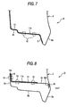
- Fig. 6 is an enlarged partial front view of the central portion of the lower end portion of the door, one portion of which is shown in the view.
- Fig. 7 is an enlarged sectional view taken on line A - A in Fig. 6, and
- Fig. 8 is an enlarged sectional view taken on line B - B in Fig. 6.
- Fig. 9 is an enlarged perspective view of portion C of Fig. 6.
- the connecting portion 11e is formed being protruded from the lower end portion of the front frame member 11 toward the rear frame member 12 and fixed to the lower frame 16 and the outer panel 2.
- the connecting portion 11e is fixed in such a manner that structural adhesive S is coated on the portion of adhesive allowance S1 (the hatched portions shown in Figs. 6 and 9) which is formed between the connecting portion 11e and the upper face of the inside plate 2b folded back and extended from the outside plate 2a of the outer panel 2. Further, the connecting portion 11e is also fixed by the rivets 10.
- the connecting portion 11e is fixed in such a manner that structural adhesive S is coated in portions of adhesive allowances S2 and S3 (the hatched portions shown in Figs. 6 and 9) formed between the connecting portion 11e and the front end portion 16a of the lower frame 16 and between the connecting portion 11e and the inside plate 2b of the outer panel 2. Further, the connecting portion 11e is also fixed by the rivets 10.
- the front side face 11f is a portion forming a front side face of the door body 1.
- the outside peripheral portion 11h is located at the front end of the door body 1 and at the lower end on the front side.
- the outer panel 2 (shown in Fig. 2) is attached to this outside peripheral portion 11h by structural adhesive S and hemming working.
- the bracket 19 is integrally fixed to a lower portion of the engaging groove 11b of the front frame member 11 by means of welding.
- the front end portion 17a of the door beam 17 is fixed to this bracket 19 by means of welding.
- the rear frame member 12 is a member forming the frame on the rear side of the door body 1.
- the rear frame member 12 is made of an aluminum die-cast product of light metal such as aluminum.
- This rear frame member 12 includes: a sash attaching portion 12a to which the outside door sash 15 is fixed; an engaging groove 12b to which the upper inner frame 13 is fixed; a fixing face 12c to which the door beam 17 is fixed; and a connecting portion 12d to which the lower frame 16 is fixed.
- the sash attaching portion 12a and the engaging groove 12b are arranged in the upper end portion of the rear frame member 12.
- the fixing face 12c and the connecting portion 12d are arranged in the lower end portion of the rear frame member 12.
- the joining face 12e formed in the rear lower end portion 15b of the outside door sash 15 is joined to an upper end portion of the rear frame member 12.
- the joining face 12e formed in the rear lower end portion 15b of the outside door sash 15 is bonded to the upper end portion of the rear frame member 12 by structural adhesive S and further strongly fixed by the rivets.
- the upper outer frame 14 is fixed to the rear end portion 15b of the outside door sash 15, which is fixed to the sash attaching portion 12a, by an adhesive sealing member such as a mastic sealer.
- the engaging groove 12b is a substantially U-shaped groove formed in the front portion in the neighborhood of the sash attaching portion 12a.
- the rear end portion 13b of the upper inner frame 13 is engaged in this engaging groove 12b and also fixed to this engaging groove 12b by structural adhesive S.
- the fixing face 12c is a flat face formed in the lower front end portion of the rear frame member 12.
- the lower end portion 17b of the door beam 17 is fixed to this fixing face 12c by structural adhesive S.
- the connecting portion 12d is formed symmetrical to the connecting portion 11e described before.
- the connecting portion 12d is protruded from the lower end portion of the rear frame member 12 toward the front frame member 11 and fixed to the lower frame 16 and the outer panel 2.
- Fig. 10 is an enlarged perspective view of portion H of Fig. 6.
- the connecting portion 12d is fixed in such a manner that structural adhesive S is coated on the portion of adhesive allowance S4 (the hatched portions shown in Figs. 6 and 10) which is formed between the connecting portion 12d and the upper face of the inside plate 2b folded back and extended from the outside plate 2a of the outer panel 2. Further, the connecting portion 12d is also fixed by the rivets 10.
- the lower frame 16 is made in such a manner that a rolled sheet, which is made of light metal such as aluminum alloy or magnesium alloy, is formed into the lower frame 16 by means of press-forming. Alternatively, the lower frame 16 is made of an extruded material.
- the lower frame 16 is a plate member extending in the longitudinal direction of the vehicle.
- the lower frame 16 forms a lower frame portion of the door body 1, the profile of which is formed into projected parallels.
- the lower frame 16 includes: a front end portion 16a, rear end portion 16b, inside flange 16c and outside flange 16d.
- the lower frame 16 is fixed in such a manner that the front end portion 16a is fixed to the front frame member 11 and the rear end portion 16b is fixed to the rear frame member 12 by both structural adhesive S and the rivets 10.
- the inside flange 16c is formed being extended upward along the forward end portion 2c of the inside panel 2b of the outer panel 2.
- the inside flange 16c is fixed in such a manner that adhesive allowance S3 (shown in Fig. 6) of the inside plate 2b is fixed by both structural adhesive S and the rivets 10.
- the outside flange 16d is connected in such a manner that adhesive allowance M1 (shown in Fig. 6) between the outside flange 16d and the outside plate 2a of the outer panel 2 is connected by an adhesive sealing member M so that the outside flange 16d can be relatively displaced with respect to the outside plate 2a of the outer panel 2.
- adhesive sealing member M is made of mastic sealer or hot melt.
- the upper inner frame 13 is made of an extruded material of light metal such as aluminum alloy or magnesium alloy.
- This upper inner frame 13 includes: a front end portion 13a fixed to the front frame member 11; a rear end portion 13b fixed to the rear frame member 12; an opening portion 13c open to the outside of the vehicle in the width direction; a buffer action portion 13d, the cross section of which is formed into a substantial C-shape; a pair of flanges 13e, 13f, which are directed inward, extending in the width direction facing the opening 13c; curved portions 13g, 13h curved to the inside of the vehicle; and a guide portion 13k of the windowpane 31 (shown in Fig.
- this upper inner frame 13 is connected to the front frame member 11, and the other end portion of this upper inner frame 13 is connected to the rear frame member 12, and this upper inner frame 13 is extended in the longitudinal direction of the vehicle body.
- the upper outer frame 14 is made of an extruded material of aluminum alloy extending in the longitudinal direction of the vehicle body.
- the upper outer frame 14 is arranged substantially in parallel with the upper inner frame 13 outside the vehicle.
- the upper outer frame 14 includes: a front end portion 14a fixed to the front frame member 11; a rear end portion 14b fixed to the rear frame member 12; an upper end portion 14c to which the outer panel 2 is attached by hemming working; and a lower end portion 14d fixed to the outer panel 2 by a plurality of adhesive sealing members M.
- the outside door sash 15 includes: an upper sash member 151; and a rear sash member 152 made of an extruded material of light metal such as aluminum alloy, wherein the upper sash member 151 and the rear sash member 152 are welded to each other at the upper end portion.
- the upper sash member 151 and the rear sash member 152 may be integrally formed with each other.
- the rear sash member 152 may be integrally formed with the rear frame ember 12 at the upper portion.
- the door beam 17 is a reinforcing member made of light metal such as aluminum alloy.
- This door beam 17 includes a pipe-shaped member, the cross section of which is substantially square when the door beam 17 is obliquely arranged with respect to the door body 1.
- the door beam 17 is arranged in such a manner that the front end portion 17a of the door beam 17 is set higher than the rear end portion 17b, and the front end portion 17a is connected to the front frame member 11 and the rear end portion 17b is connected to the rear frame member 12.
- the outer panel 2 is made in such a manner that a rolled sheet, which is made of light metal such as aluminum alloy, is formed into the outer panel 2 by means of press-forming.
- This outer panel 2 is attached to the circumferential edge of the frame portion, which is formed into a profile of projected parallels, of the door body 1 by both hemming working and structural adhesive S.
- the outer panel 2 is constituted in such a manner that the outside plate 2a, inside plate 2b, upper end portion 2d, front end portion 2e and rear end portion 2f are integrally formed by means of press-forming.
- the outside plate 2a is arranged being extended downward from the outside of the vehicle in which the lower frame 2 of the outer panel 2 is provided.
- the outside plate 2a is connected with the outside flange 16d of the lower frame 16 and the door beam 17 by adhesive sealing member M.
- the inside plate 2b is folded back to an upper portion of the outside plate 2a and extended to the inside of the vehicle of the lower frame 16.
- the inside plate 2b is fixed to the connecting portion 11e of the front frame member 11, the connecting portion 12d of the rear frame member 12 and the lower frame 16 by both structural adhesive S and the rivets 10.
- the upper end portion 2d is fixed to the upper outer frame 14 by both hemming working and structural adhesive S.
- the front end portion 2e is fixed to the front frame member 11 by both hemming working and structural adhesive S.
- the rear end portion 2f is fixed to the rear frame member 12 by both hemming working and structural adhesive S.
- the window device 3 is explained below.
- the window device 3 is arranged in the door body 1 inside the vehicle.
- the window device 3 includes: a windowpane 31; guide members 32, 33 for supporting this windowpane 31; a guide rail 34 for guiding an elevating motion of the windowpane 31; and a window regulator 35 for elevating the windowpane 31.
- the guide member 32 is made of light metal such as aluminum alloy and fixed to the front frame member 11 inside the vehicle.
- the guide member 33 is made of light metal such as aluminum alloy and fixed to the rear frame member 12 inside the vehicle.
- the guide rail 34 is made of light metal such as aluminum alloy, and the upper end portion of the guide rail is fixed to the upper inner frame 13 and the lower end portion of the guide rail is fixed to the lower frame 16.
- the window regulator 35 is arranged on the guide rail 34.
- the lining 4 is a plate member constituting the interior of door D.
- the inside handle 5, speaker 7 and harness 8 are arranged on this lining 4, and the lining 4 is fixed to the door body 1 inside the vehicle.
- the door lock device 6 is previously attached to the door body 1.
- the inside door handle 5 and harness 8 are attached to the door lock device 6 when the lining 4 is assembled to the door body 1.
- the frame body which is formed in to a profile of projected parallels, includes the front frame member 11, rear frame member 12, upper inner frame 13, upper outer frame 14 and lower frame 16, so that the frame body can be reinforced. Therefore, the rigidity of the door body 1 can be enhanced.
- the lower frame 16 is arranged between the front frame member 11 and the rear frame member 12 in the longitudinal direction of the vehicle which is the same as the direction of the load (the direction of arrow E).
- the lower frame 16 is connected to the front frame member 11 and the rear frame member 12. Therefore, the lower frame 16 functions as a prop for supporting a load given to a lower portion of the front frame 11 in the direction of arrow E.
- a cylindrical closed cross section is formed by the outside plate 2a and the inside plate 2b of the outer panel 2. Therefore, when the lower frame 16 receives a compression load, twist load and tensile load in the direction of arrow E (shown in Fig. 3), the lower frame 16 is seldom bent, that is, the rigidity of the lower frame 16 is high.
- the door beam 17 is arranged in such a manner that the door beam 17 is inclined between the front frame member 11 and the rear frame member 12. Since the door body 1 is provided with this door beam 17, the rigidity of the door body 1 can be further enhanced with respect to the compression load, twist load and tensile load which act in the direction of arrow E. Therefore, even when the door body 1 is given a load in the direction of arrow E, the door body 1, which is formed into a profile of projected parallels, is seldom deformed. Accordingly, the lower frame 16 and the outside door sash 15 can be reinforced, that is, these components can be prevented from being deformed by an impact given to the door body 1.
- the collision load is first given to the outer panel 2 of door D.
- the collision load is successively given to the lower frame 16, door beam 17, front frame member 11 and rear frame member 12. Since the closed cross section is formed in the lower portion of the door body 1 by the lower frame 16, outside plate 2a of the outer panel 2 and inside plate 2b, this closed cross section prevents the deformation from extending into the vehicle. Therefore, passenger G can be protected from the collision.
- the lower frame 16 is attached as follows.
- the inside flange 16c is fixed to the inside plate 2b, and the outside flange 16d is connected to the outside plate 2a so that the outside flange 16d can be relatively displaced with respect to the outside plate 2a. Since the outside flange 16d has elasticity by which the outside flange 16d can be relatively displaced, an impact given to door D can be reduced and passenger G can be prevented from the impact.
- the rigidity of the lower frame 16 constituting the door body 1 is high. Further, the door body 1 is formed into a frame which includes the front frame member 11, rear frame member 12, upper outer frame 14 and lower frame 16, that is, door D has a frame structure. Therefore, door D can be easily made of light metal such as aluminum alloy or magnesium alloy. When door D is made of light metal such as aluminum alloy or magnesium alloy, the weight of the entire door D can be reduced to 2/3 of the weight of a door made of steel. Accordingly, the weight of the entire vehicle can be reduced and the fuel consumption can be enhanced. In the case of recycling, aluminum can be recycled by a smaller quantity of energy than iron. Therefore, a load given to the global environment can be reduced.
- the upper inner frame 213 corresponds to "inner frame” described in aspects.
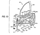
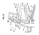
- Fig. 16 is a view showing a door for a vehicle of the embodiment of the present invention, that is, Fig. 16 is an enlarged perspective view showing a primary portion in a connecting state in which the upper inner frame and the front frame member are connected with each other, wherein this view is taken from the outside of the vehicle.
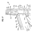
- Fig. 17 is a view showing a door for a vehicle of the embodiment of the present invention, that is, Fig. 17 is an enlarged perspective view showing a primary portion in a connecting state in which the upper inner frame and the front frame member are connected with each other when the upper outer frame is disconnected.
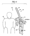
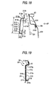
- Fig. 18 is an enlarged view showing portion H in Fig. 11.
- Fig. 19 is an enlarged sectional view taken on line 2A - 2A in Fig. 16.
- the engaging groove 211b is a substantially U-shaped groove formed in the lower side rear portion in the neighborhood of the sash attaching portion 211a.
- the engaging groove 211b is a groove used for engaging and holding the front end portion 213a of the upper inner frame 213.
- the front end portion 213a of the upper inner frame 213 is engaged in this engaging groove 211b via structural adhesive 2S. Further, the front end portion 213a of the upper inner frame 213 is fixed in this engaging groove 211b by means of riveting.
- the connecting portion 211e includes a protruding piece which protrudes from the lower end portion of the front frame member 211 toward the rear frame member 212.
- the front end portion of the lower frame 216 is bonded to this connecting portion 211e via structural adhesive 2S. Further, the front end portion of the lower frame 216 is fixed to this connecting portion 211e by means of riveting.
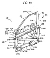
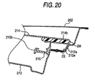
- Figs. 13, 15 and 20 are related to the rear frame member 212.
- Fig. 20 is an enlarged sectional view of Fig. 13.
- the engaging groove 212b is a substantially U-shaped groove formed in the front portion in the neighborhood of the sash attaching portion 212a.
- the engaging groove 212b is a groove to be engaged with the rear end portion 213b of the upper inner frame 213 so as to hold it.
- the connecting portion 212d is a protruding piece which protrudes from a lower end portion of the rear frame member 212 toward the front frame member 211.
- the rear end portion 216b of the lower frame 216 is bonded to this connecting portion 212d by structural adhesive 2S. Further, the rear end portion 216b of the lower frame 216 is bonded to this connecting portion 212d by means of riveting and further fixed by means of riveting.
- This upper inner frame 213 includes: a base body portion 213j, the lateral cross section of which is a substantial C-shape; and a guide portion 213k extending upward from an upper portion of this base body portion 213j along the windowpane 231 (shown in Fig. 18).
- One end portion of this upper inner frame 213 is connected to the front frame member 211, and the other end portion of this upper inner frame 213 is connected to the rear frame member 212, and this upper inner frame 213 is extended in the longitudinal direction of the vehicle body.
- the base body portion 213j includes: a front end portion 213a fixed to the front frame member 211; a rear end portion 213b fixed to the rear frame member 212; an opening portion 213c open to the outside of the vehicle in the vehicle width direction; a side face 213d formed inside the vehicle; upper and lower leg portions 213m, 213n extending outside the vehicle from the upper and the lower end portion of this side face 213d; bent portions 213g, 213h formed in the connecting portion of the side face 213d with the leg portions 213m, 213n, curved inside the vehicle; and a pair of inward flanges 213e, 213f facing the opening portion 213c, extending inward in the vertical width direction.
- the base body portion 213j includes the bent portions 213g, 213h which are formed being curved inside the vehicle. Therefore, the base body portion 213j has elasticity in the vehicle width direction.
- the opening portion 213c is formed in such a manner that the lateral cross section is formed into a substantial C-shape and extended in the longitudinal direction. Under the above condition, the opening portion 213c is interposed between the front frame member 211 and the rear frame member 212 and arranged in the door body 201 so that the opening portion 213c can be directed outside the vehicle.
- Width L2 in the vertical direction of the flanges 213e, 213f is set at 1/4 to 1/2 of width L1 in the vertical direction of the base body portion 213j.
- Width L1 in the vertical direction of the base body portion 213j is, for example, about 105 mm, and width L2 in the vertical direction of the flanges 213e, 213f is about 25 mm.
- the base end portions of the flanges 213e, 213f are bent by a relatively small radius of bending with respect to the bent portions 213g, 213h. After the base end portions of the flanges 213e, 213f are bent, they are formed flat. In the flanges 213e, 213f, a large plane is formed inward so that the guide rail 234 and the harness 208 of the window device 203 shown in Fig. 12 can be easily attached.
- Width L3 in the vehicle width direction of the upper inner frame 213 is set at 1/6 to 1/1 of width L1 in the vertical direction of the base body portion 213j. Width L3 in the vehicle width direction of the upper inner frame 213 is, for example, about 22 mm.
- the bent portion 213g on the upper side is formed being curved by an obtuse angle with respect to the side face 213d of the upper inner frame 213. Therefore, the leg portions 213m, 213n are expanded toward the outside of the vehicle in the vehicle width direction. As shown in Fig. 19, the leg portion 213m is obliquely formed being tapered so that the leg portion 213m can be easily engaged with and assembled to the front frame member 211 arranged inside the vehicle.
- the bent portion 213h on the lower side is formed being curved making a right angle with the side face 213d of the upper inner frame 213. Therefore, the leg portion 213n is formed in the horizontal direction toward the outside of the vehicle so that the leg portion 213n can be easily placed and supported on the inner face of the engaging groove 211b of the front frame member 211 arranged inside the vehicle.
- Figs. 11 and 15 are related to the outside door sash 215, lower frame 216 and door beam 217.
- the lower frame 216 is made of a rolled plate or an extruded material of light metal such as aluminum alloy.
- This lower frame 216 includes a lower frame portion of the door body 201 which is formed into a profile of projected parallels.
- the front end portion 216a of the lower frame 216 is connected to the front frame member 211 by structural adhesive 2S and by means of riveting.
- the rear end portion 216b of the lower frame 216 is connected to the rear frame member 212 by structural adhesive 2S and by means of riveting.
- the lower face of the lower frame 216 is covered with the extending portion 202a of the outer panel 202.
- Fig. 12 is related to each portion of door 2D except for the door body 201.
- the outer panel 202 is fixed as follows.
- the upper portion of the outer panel 202 is fixed to the upper outer frame 214 by both hemming working and structural adhesive 2S.
- the front end portion and lower end portion are fixed to the front frame member 211 by both hemming working and structural adhesive 2S
- the rear end portion and lower end portion are fixed to the rear frame member 212 by both hemming working and structural adhesive 2S.
- the extending portion 202a is fixed to the lower frame 216 by both hemming working and structural adhesive 2S.
- Figs. 11, 13, 14 and 18 are related to operation of the door for a vehicle of the embodiment of the present invention.
- the passenger's shoulder and arm which are located on the outermost side of vehicle room 2R, are located on the side of the upper inner frame 213 inside the vehicle.
- the frame body which is formed in to a profile of projected parallels, includes the front frame member 211, rear frame member 212, upper inner frame 213, upper outer frame 214 and lower frame 216, so that the frame body can be reinforced. Therefore, the rigidity of the door body 201 can be enhanced.
- the upper inner frame 213 is arranged between the front frame member 211 and the rear frame member 212 in the longitudinal direction of the vehicle which is the same as the direction of the load (the direction of arrow 2E).
- the lower frame 216 is connected to the front frame member 211 and the rear frame member 212. Therefore, the upper inner frame 213 functions as a prop for supporting a load given to a lower portion of the front frame 211 in the direction of arrow 2E.
- width L2 in the vertical direction of the flanges 213e, 213f of the upper inner frame 213 is set at 1/4 to 1/2 of width L1 in the vertical direction of the base body portion 213j
- width L3 in the vehicle width direction of the base body portion 213j is set at 1/6 to 1/1 of width L1 in the vertical direction of the base body portion 213j
- the cross section of the upper inner frame 213 is formed into a substantial C-shape. Therefore, since the lateral cross-sectional area of the upper inner frame 213 is large, when the upper inner frame 213 is given a compression load, twist load and tensile load, the direction of which is indicated by arrow 2E (shown in Fig. 14), buckling seldom occurs in the upper inner frame 213, that is, the rigidity of the upper inner frame 213 is high.
- the collision load is successively given to the upper outer frame 214, door beam 217, the lower frame 216, front frame member 211 and rear frame member 212. Since the upper inner frame 213 is arranged inside the vehicle of the upper outer frame 214, the upper outer frame 214 can prevent the door body from being deformed inside the vehicle by a collision load. Therefore, passenger 2G (shown in Fig. 11) can be protected from the damage caused by an impact force.
- the door body has a buffer action property.
- width L3 in the vehicle width direction of the base end portion 213j is set at 1/6 to 1/1 of width L1 in the vertical direction, the base end portion 213j is collapsed by passenger 2G (shown in Fig. 11). Therefore, an impact force can be reduced by the base end portion 213j, and passenger 2G can be protected from the damage caused by the impact force.
- the rigidity of the upper inner frame 213 constituting the door body 201 is high. Further, the door body 201 is formed into a frame which includes the front frame member 211, rear frame member 212, upper outer frame 214 and lower frame 216, that is, door 2D has a frame structure. Therefore, door 2D can be easily made of light metal such as aluminum alloy or magnesium alloy.
- the lower portion of the door when the outside plate and inside plate of the outer panel and the lower frame form a closed cross section in the lower portion of the door body, the lower portion of the door can be reinforced and the rigidity can be enhanced. Due to the foregoing, for example, in case where a vehicle collides with another one and a collision load is given to the door of the vehicle, since the door body has a portion, the profile of which is a closed cross section, including the lower frame and the outer panel, this portion, the profile of which is a closed cross section, receives a compression load, tensile load and twist load which are given in the vehicle collision. Therefore, the lower portion of the door is provided with a sufficiently high rigidity.
- a door for a vehicle includes: a door body including a front frame member, including a rear frame member arranged on the rear side of the vehicle and including a lower frame for connecting the front frame member with the rear frame member; and an outer panel including an outside plate for forming a surface of the vehicle of the lower frame outside the vehicle and an inside plate folded back at a lower end portion of the outside plate, the inside plate extending to the inside of the vehicle of the lower frame. Therefore, the door body can have a frame structure. For the above reasons, even when the door body includes members made of aluminum or magnesium, the press-forming property of which is low, the door can be easily made by connecting these members. Due to the foregoing, the door can be made of light metal. Therefore, the weight of the entire vehicle can be reduced and the fuel consumption can be enhanced.
- the lower portion of the door can be reinforced.
- this portion, the profile of which is a closed cross section, including the lower frame and the outer panel since the door body has a portion, the profile of which is a closed cross section, including the lower frame and the outer panel, this portion, the profile of which is a closed cross section, can receive a compression load, tensile load and twist load which are given in the vehicle collision. Therefore, in the case where the door body has a frame structure, it is possible to prevent the frame structure from buckling.
- the lower frame includes an outside flange connected to the outside plate so that the outside flange can be relatively displaced with respect to the outside plate. Therefore, the outside flange is not fixed to the outside plate by means of welding or fastening in which a fastening member is used. For the above reasons, it is possible to prevent the formation of a trace of welding or deformation on a face of the outside plate. That is, the face of the outside plate can be beautifully finished.
- the outside flange when the outside flange is connected to the outside plate by an adhesive sealing member, the outside flange can be connected by a simple means so that the outside flange can be displaced with respect to the outside plate. Since the outside flange is connected to the outside plate of the outer panel by the adhesive sealing member, there is no possibility that a face of the outside plate outside the vehicle is deformed by the member connected. Therefore, the face of the outside plate on the outside of the vehicle can be beautifully finished.
- the inside flange of the lower frame is formed extending upward along the inside plate, the inside flange is arranged in an upper portion of the closed cross section formed by the lower frame and the outer panel. Therefore, in the case of working in which the inside flange is fixed to the door body, working can be easily conducted since the inside flange is located in the upper portion of the closed cross section.
- the inside flange is arranged being put on the inside plate of the outer panel, the mechanical strength of the portion, in which the inside flange is put on the inside plate of the outer panel, can be enhanced. Therefore, the portion, in which the inside flange is put on the inside plate of the outer panel, can be used as a space in which the other parts such as a window regulator are arranged.
- the outer panel is formed by means of press-forming. Therefore, the outer panel can be made of material used for press-forming, the mechanical strength of which is high. Accordingly, the rigidity of the closed cross section can be enhanced, and the productivity can be also enhanced.
- the door body since the door body includes an inner frame extending in the longitudinal direction of the vehicle, the inner frame receives a compression load, tensile load and twist load given to the door body in the collision. Therefore, the rigidity of the door body can be enhanced. Therefore, the door can be made of light metal such as aluminum alloy or magnesium alloy. Accordingly, the weight of the entire vehicle can be reduced, and the fuel consumption can be enhanced. Since the inner frame is provided with an opening and the cross section of the inner frame is formed into a substantial C-shape, the inner frame is relatively liable to be deformed. Therefore, the door body has a buffer action property. Accordingly, it is possible to protect the passenger from an impact force caused in the collision. In this way, the inner frame can be provided with the rigidity, and further the buffer action property of the inner frame can be appropriately enhanced.
- the door body includes: a front frame member; a rear frame member; and an inner frame for connecting the front frame member with the rear frame member. Therefore, it is possible to form the door body into a frame structure. Accordingly, even when the members are made of material such as aluminum or magnesium, the press-forming property of which is low, the door can be easily made by connecting these members. Due to the foregoing, the door can be made of light metal, and the weight of the entire vehicle can be reduced and the fuel consumption can be enhanced.
- the inner frame In the case where a passenger bumps against the inner frame inside the vehicle, the inner frame, the cross section of which is formed into a substantial C-shape, is arranged in the door body in such a manner that the opening portion of the inner frame is directed outside the vehicle. Therefore, when an impact force, the intensity of which is not less than a predetermined value, is given to upper and lower edges of the opening portion or a portion inside the vehicle with respect to the opening portion of the inner frame, the inner frame is bent and the passenger can be received by a large face, that is, the inner frame is provided with a buffer action property. Therefore, it is possible to protect the passenger from the impact force.
- the inner frame includes a pair of flanges extending toward the inside of the opening, and the width of each flange in the vertical direction is set at 1/4 to 1/2 of the width in the vertical direction of the base portion. Due to the foregoing, a large lateral cross-sectional area of the inner frame can be formed. Therefore, the rigidity can be enhanced. When the vehicle comes into a head-on collision with another one in which an impact force is given to the vehicle in the front portion, since the inner frame is provided with the flange, the rigidity of the inner frame is high. Therefore, even when the inner frame is given a compression load, twist load and tensile load, bending and twisting are seldom caused in the inner frame, that is, the door can be appropriately reinforced.
- the width of the inner frame in the width direction of the vehicle is set at 1/6 to 1/1 of the width in the vertical direction of the base portion. Therefore, the inner frame can easily receive bending moment. Accordingly, the inner frame can be provided with an appropriately high rigidity and buffer action property. For example, in the case where the vehicle collides with another one and the passenger bumps against the door inside the vehicle, since the inner frame is provided with a width in the width direction of the vehicle, when an impact force in the vehicle width direction, the intensity of which is not less than a predetermined value, is given, these portions having the width in the vehicle width direction are bent being pushed by the passenger, so that the impact force given to the passenger can be reduced. Accordingly, the passenger can be protected from the damage caused by the impact force.
- the door for a vehicle of the present invention described in aspect 11 in the case where the vehicle comes into a collision with another one and the passenger bumps against the inner frame from the inside of the vehicle, since the side of the inner frame inside the vehicle and the upper and the lower leg portion extending from the upper and the lower end portion of the side to the outside of the vehicle are formed being curved, it is possible to avoid the occurrence of stress concentration upon the connecting portion, and the collision load can be positively received. Since a hollow swelling portion is formed, the passenger can be softly received and protected from an impact force.
Landscapes
- Engineering & Computer Science (AREA)
- Mechanical Engineering (AREA)
- Body Structure For Vehicles (AREA)
Applications Claiming Priority (4)
| Application Number | Priority Date | Filing Date | Title |
|---|---|---|---|
| JP2003108329 | 2003-04-11 | ||
| JP2003108326A JP4287689B2 (ja) | 2003-04-11 | 2003-04-11 | 車両用ドア |
| JP2003108329A JP2004314697A (ja) | 2003-04-11 | 2003-04-11 | 車両用ドア |
| JP2003108326 | 2003-04-11 |
Publications (2)
| Publication Number | Publication Date |
|---|---|
| EP1468855A2 true EP1468855A2 (de) | 2004-10-20 |
| EP1468855A3 EP1468855A3 (de) | 2006-04-26 |
Family
ID=32911474
Family Applications (1)
| Application Number | Title | Priority Date | Filing Date |
|---|---|---|---|
| EP04008543A Withdrawn EP1468855A3 (de) | 2003-04-11 | 2004-04-08 | Fahrzeugtür |
Country Status (2)
| Country | Link |
|---|---|
| US (1) | US7097742B2 (de) |
| EP (1) | EP1468855A3 (de) |
Cited By (3)
| Publication number | Priority date | Publication date | Assignee | Title |
|---|---|---|---|---|
| FR2888534A1 (fr) * | 2005-07-12 | 2007-01-19 | Renault Sas | Porte de vehicule automobile renforcee a l'egard des chocs lateraux. |
| EP2522536A1 (de) * | 2011-05-10 | 2012-11-14 | Autotech Engineering, A.I.E. | Fensterrahmen für Fahrzeugtüren und Verfahren zur Herstellung eines solchen |
| US11186147B2 (en) | 2019-06-10 | 2021-11-30 | Nissan North America, Inc. | Vehicle door assembly |
Families Citing this family (27)
| Publication number | Priority date | Publication date | Assignee | Title |
|---|---|---|---|---|
| US20040144142A1 (en) * | 1999-11-18 | 2004-07-29 | Strattec Security Corporation | Modular vehicle door lock and latch system and method |
| US6530251B1 (en) * | 1999-11-18 | 2003-03-11 | Strattec Security Corporation | Modular vehicle door lock and latch system and method |
| JP2005212646A (ja) * | 2004-01-30 | 2005-08-11 | Hirotec Corp | 車両用ドア |
| EP1580056B1 (de) * | 2004-03-25 | 2011-10-12 | Aisin Seiki Kabushiki Kaisha | Türrahmen-Struktur |
| US7448670B2 (en) * | 2005-01-10 | 2008-11-11 | Noble Advanced Technologies, Inc. | Vehicle door reinforcement |
| JP4848913B2 (ja) * | 2005-11-28 | 2011-12-28 | 三菱自動車工業株式会社 | ドア構造 |
| DE102006035307A1 (de) * | 2005-12-27 | 2007-07-05 | Toyota Jidosha Kabushiki Kaisha, Toyota | Tür für ein Fahrzeug |
| US20070222256A1 (en) * | 2006-03-23 | 2007-09-27 | Jeffrey Valentage | Hybrid door core and trim module with integrated components |
| KR101097018B1 (ko) * | 2007-03-30 | 2011-12-20 | 가부시키가이샤 고베 세이코쇼 | 측면 충돌 성능을 강화시킨 자동차용 도어 |
| DE102007052618A1 (de) * | 2007-11-05 | 2009-05-07 | GM Global Technology Operations, Inc., Detroit | Einrichtung zur Führung einer Fallscheibe |
| WO2010024817A1 (en) * | 2008-08-29 | 2010-03-04 | Lear Corporation | Vehicle seat frame and method of making |
| US8322078B2 (en) * | 2010-01-13 | 2012-12-04 | Ford Global Technologies, Llc | Inner panel design for automotive door header |
| JP5692776B2 (ja) * | 2010-06-11 | 2015-04-01 | シロキ工業株式会社 | 車両用ドアフレーム |
| JP5710223B2 (ja) * | 2010-11-19 | 2015-04-30 | シロキ工業株式会社 | 軽金属材料からなるドアフレームの製造方法 |
| JP6033619B2 (ja) * | 2012-09-13 | 2016-11-30 | テイ・エス テック株式会社 | 車両用シート |
| US8979161B2 (en) * | 2013-03-15 | 2015-03-17 | GM Global Technology Operations LLC | Low mass truck end gate utilizing aluminum stampings and extrusions |
| JP6150573B2 (ja) * | 2013-03-21 | 2017-06-21 | シロキ工業株式会社 | ドア |
| US9045025B1 (en) | 2014-04-30 | 2015-06-02 | Spintek Filtration, Inc. | Articulated gull wing door |
| KR101637785B1 (ko) * | 2014-12-22 | 2016-07-08 | 현대자동차주식회사 | 자동차용 하이브리드 도어 |
| JP6245188B2 (ja) * | 2015-02-06 | 2017-12-13 | トヨタ自動車株式会社 | 車両用ドアフレーム構造 |
| JP6157682B2 (ja) * | 2015-08-06 | 2017-07-05 | 株式会社神戸製鋼所 | ドアビーム及びドアビームの取付構造 |
| JP6387981B2 (ja) * | 2016-02-19 | 2018-09-12 | マツダ株式会社 | 自動車のドア構造 |
| KR20180071436A (ko) * | 2016-12-19 | 2018-06-28 | 현대자동차주식회사 | 도어 임팩트 빔 및 그 제조방법 |
| JP7124302B2 (ja) * | 2017-11-30 | 2022-08-24 | トヨタ紡織株式会社 | 乗物用ドア |
| KR20190071023A (ko) * | 2017-12-13 | 2019-06-24 | 현대자동차주식회사 | 차량용 도어 |
| KR20190071024A (ko) * | 2017-12-13 | 2019-06-24 | 현대자동차주식회사 | 차량용 도어 |
| CN116674358B (zh) * | 2023-05-29 | 2025-10-31 | 奇瑞汽车股份有限公司 | 一种车门内板可折叠的车门结构 |
Family Cites Families (33)
| Publication number | Priority date | Publication date | Assignee | Title |
|---|---|---|---|---|
| DE3004897A1 (de) * | 1980-02-09 | 1981-08-27 | Audi Nsu Auto Union Ag, 7107 Neckarsulm | Fahrzeugtuere, insbesondere seitentuere eines pkw |
| US4561211A (en) * | 1983-08-05 | 1985-12-31 | General Motors Corporation | Vehicle door and window assembly |
| US4575968A (en) * | 1983-11-14 | 1986-03-18 | Excel Industries, Inc. | Vehicle door assembly |
| US4843762A (en) * | 1987-04-14 | 1989-07-04 | The Budd Company | Vehicle door with split outer panel |
| US4823507A (en) * | 1987-06-24 | 1989-04-25 | General Motors Corporation | Window regulator mechanism for frameless windows |
| US4924630A (en) * | 1988-04-05 | 1990-05-15 | Hoover Universal, Inc. | Functional door cartridge and method of manufacturing thereof |
| JP2620877B2 (ja) * | 1988-11-08 | 1997-06-18 | 本田技研工業株式会社 | 車両のセンタピラー構造 |
| GB2230558A (en) * | 1989-04-15 | 1990-10-24 | Ford Motor Co | Regulating system for motor vehicle window |
| US4949509A (en) * | 1989-06-12 | 1990-08-21 | Gold Peter N | Automotive window mounting assembly |
| DE3921289C1 (de) * | 1989-06-29 | 1991-01-10 | Brose Fahrzeugteile Gmbh & Co Kg, 8630 Coburg, De | |
| US5007201A (en) * | 1990-04-04 | 1991-04-16 | Excel Industries, Inc. | Door construction |
| US5034173A (en) * | 1990-04-26 | 1991-07-23 | General Motors Corporation | Method of manufacturing a plastic motor vehicle door |
| US5035083A (en) * | 1990-07-30 | 1991-07-30 | Ford Motor Company | Unitized window system for a vehicle door |
| CA2054577C (en) * | 1991-01-25 | 1996-03-12 | Larry Holt | Module for vehicle door |
| JP3521452B2 (ja) * | 1992-11-09 | 2004-04-19 | マツダ株式会社 | 自動車のドア構造 |
| DE4241678A1 (de) * | 1992-12-11 | 1994-06-16 | Ymos Ag Ind Produkte | Tür für ein Kraftfahrzeug |
| DE4306668A1 (de) * | 1993-03-04 | 1994-09-08 | Ymos Ag Ind Produkte | Fahrzeugtür, insbesondere Kraftfahrzeugtür |
| US5884960A (en) * | 1994-05-19 | 1999-03-23 | Henkel Corporation | Reinforced door beam |
| US6168226B1 (en) * | 1994-05-19 | 2001-01-02 | Henkel Corporation | Composite laminate automotive structures |
| DE19616788A1 (de) * | 1996-04-26 | 1997-11-06 | Bayerische Motoren Werke Ag | Fahrzeugtür |
| GB9617549D0 (en) * | 1996-08-21 | 1996-10-02 | Rover Group | Vehicle door structures |
| US6096403A (en) * | 1997-07-21 | 2000-08-01 | Henkel Corporation | Reinforced structural members |
| DE19732225B4 (de) * | 1997-07-26 | 2004-05-19 | Kiekert Ag | Kraftfahrzeugtür |
| DE59813386D1 (de) * | 1997-11-13 | 2006-04-20 | Schade Gmbh & Co Kg | Rohbautür eines Fahrzeugs |
| US6022066A (en) * | 1998-10-15 | 2000-02-08 | Ricon Corporation | Door extension for vehicle doors |
| DE19850150A1 (de) * | 1998-10-30 | 2000-05-04 | Schade Gmbh & Co Kg | Fahrzeugtür |
| DE19852234B4 (de) * | 1998-11-12 | 2006-06-01 | Volkswagen Ag | Mehrteiliges Verschlußteil für Kraftfahrzeuge mit einem Innenteil aus Leichtmetallguß |
| IT1307002B1 (it) * | 1999-01-22 | 2001-10-11 | E M A R C S P A | Ossatura per porta d'autoveicolo e porta che la comprende. |
| IT1320019B1 (it) * | 2000-04-05 | 2003-11-12 | U T S S P A | Porta di un autoveicolo munita di un pannello esterno di copertura. |
| JP2001334955A (ja) | 2000-05-29 | 2001-12-04 | Toyota Motor Corp | 車輌のドアの補強構造 |
| JP3580225B2 (ja) | 2000-06-02 | 2004-10-20 | 日産自動車株式会社 | 車両用ドア構造 |
| US6454884B1 (en) * | 2000-06-12 | 2002-09-24 | Pullman Industries, Inc. | Method of manufacturing a vehicle structural beam |
| DE10063417A1 (de) * | 2000-12-19 | 2002-07-04 | Wagon Automotive Gmbh | Leichtbautür für Kraftfahrzeuge |
-
2004
- 2004-04-08 EP EP04008543A patent/EP1468855A3/de not_active Withdrawn
- 2004-04-09 US US10/821,702 patent/US7097742B2/en not_active Expired - Fee Related
Non-Patent Citations (1)
| Title |
|---|
| None |
Cited By (5)
| Publication number | Priority date | Publication date | Assignee | Title |
|---|---|---|---|---|
| FR2888534A1 (fr) * | 2005-07-12 | 2007-01-19 | Renault Sas | Porte de vehicule automobile renforcee a l'egard des chocs lateraux. |
| WO2007006986A3 (fr) * | 2005-07-12 | 2007-03-08 | Renault Sa | Porte de vehicule automobile renforcee a l'egard des chocs lateraux |
| US7967368B2 (en) | 2005-07-12 | 2011-06-28 | Renault S.A.S. | Motor vehicle door which is reinforced against side impacts |
| EP2522536A1 (de) * | 2011-05-10 | 2012-11-14 | Autotech Engineering, A.I.E. | Fensterrahmen für Fahrzeugtüren und Verfahren zur Herstellung eines solchen |
| US11186147B2 (en) | 2019-06-10 | 2021-11-30 | Nissan North America, Inc. | Vehicle door assembly |
Also Published As
| Publication number | Publication date |
|---|---|
| US20040216387A1 (en) | 2004-11-04 |
| EP1468855A3 (de) | 2006-04-26 |
| US7097742B2 (en) | 2006-08-29 |
Similar Documents
| Publication | Publication Date | Title |
|---|---|---|
| EP1468855A2 (de) | Fahrzeugtür | |
| JP5407372B2 (ja) | 車両の側部車体構造 | |
| RU2226468C2 (ru) | Интегральный элемент жесткости внутренней части двери | |
| US5671968A (en) | Body structure for motor vehicle | |
| EP1991435B1 (de) | Fahrzeugaufbauseitenstruktur | |
| EP1465786B1 (de) | Fahrzeugtür | |
| US6575525B2 (en) | Reinforced door frame for a motor vehicle | |
| JP2011088596A (ja) | 車両の車体構成部材 | |
| RU116827U1 (ru) | Стойка транспортного средства с отверстием, имеющим отогнутую под углом кромку (варианты) | |
| US7316446B2 (en) | Supporting part of a vehicle door | |
| CN108454710A (zh) | 包括门槛板上的加固件的车身 | |
| US20110248527A1 (en) | Roof side structure of vehicle body | |
| CN113348100B (zh) | 汽车车门 | |
| US11052734B2 (en) | Vehicle door structure | |
| JPH11310036A (ja) | 車両用側部ドア構造 | |
| JP4287689B2 (ja) | 車両用ドア | |
| US11235813B2 (en) | Side vehicle-body structure of vehicle | |
| JP2004314697A (ja) | 車両用ドア | |
| EP3950467B1 (de) | Zusammengesetztes längliches element | |
| JPH08332975A (ja) | 車体の後部構造 | |
| JP2000103360A (ja) | 車両の車体構造 | |
| CN112429092B (zh) | 车辆的侧部车身构造 | |
| JP2020203509A (ja) | 側部車体構造 | |
| JP2592603Y2 (ja) | 自動車用ドア | |
| KR20250153252A (ko) | 자동차의 서브프레임 구조 |
Legal Events
| Date | Code | Title | Description |
|---|---|---|---|
| PUAI | Public reference made under article 153(3) epc to a published international application that has entered the european phase |
Free format text: ORIGINAL CODE: 0009012 |
|
| AK | Designated contracting states |
Kind code of ref document: A2 Designated state(s): AT BE BG CH CY CZ DE DK EE ES FI FR GB GR HU IE IT LI LU MC NL PL PT RO SE SI SK TR |
|
| AX | Request for extension of the european patent |
Extension state: AL HR LT LV MK |
|
| PUAL | Search report despatched |
Free format text: ORIGINAL CODE: 0009013 |
|
| AK | Designated contracting states |
Kind code of ref document: A3 Designated state(s): AT BE BG CH CY CZ DE DK EE ES FI FR GB GR HU IE IT LI LU MC NL PL PT RO SE SI SK TR |
|
| AX | Request for extension of the european patent |
Extension state: AL HR LT LV MK |
|
| 17P | Request for examination filed |
Effective date: 20060704 |
|
| AKX | Designation fees paid |
Designated state(s): DE GB |
|
| 17Q | First examination report despatched |
Effective date: 20080624 |
|
| GRAP | Despatch of communication of intention to grant a patent |
Free format text: ORIGINAL CODE: EPIDOSNIGR1 |
|
| INTG | Intention to grant announced |
Effective date: 20140312 |
|
| STAA | Information on the status of an ep patent application or granted ep patent |
Free format text: STATUS: THE APPLICATION IS DEEMED TO BE WITHDRAWN |
|
| 18D | Application deemed to be withdrawn |
Effective date: 20140723 |