EP1464429B1 - Entgratverfahren - Google Patents
Entgratverfahren Download PDFInfo
- Publication number
- EP1464429B1 EP1464429B1 EP20040011584 EP04011584A EP1464429B1 EP 1464429 B1 EP1464429 B1 EP 1464429B1 EP 20040011584 EP20040011584 EP 20040011584 EP 04011584 A EP04011584 A EP 04011584A EP 1464429 B1 EP1464429 B1 EP 1464429B1
- Authority
- EP
- European Patent Office
- Prior art keywords
- burr
- cutter
- steel piece
- cutting edge
- edge
- Prior art date
- Legal status (The legal status is an assumption and is not a legal conclusion. Google has not performed a legal analysis and makes no representation as to the accuracy of the status listed.)
- Expired - Lifetime
Links
- 238000000034 method Methods 0.000 title claims abstract description 31
- 229910000831 Steel Inorganic materials 0.000 claims abstract description 102
- 239000010959 steel Substances 0.000 claims abstract description 102
- 238000005520 cutting process Methods 0.000 claims abstract description 59
- 238000003466 welding Methods 0.000 description 14
- 238000005096 rolling process Methods 0.000 description 7
- 230000000694 effects Effects 0.000 description 2
- 239000012530 fluid Substances 0.000 description 1
- 238000010438 heat treatment Methods 0.000 description 1
- 230000002093 peripheral effect Effects 0.000 description 1
- 238000003825 pressing Methods 0.000 description 1
Images


Classifications
-
- B—PERFORMING OPERATIONS; TRANSPORTING
- B23—MACHINE TOOLS; METAL-WORKING NOT OTHERWISE PROVIDED FOR
- B23D—PLANING; SLOTTING; SHEARING; BROACHING; SAWING; FILING; SCRAPING; LIKE OPERATIONS FOR WORKING METAL BY REMOVING MATERIAL, NOT OTHERWISE PROVIDED FOR
- B23D79/00—Methods, machines, or devices not covered elsewhere, for working metal by removal of material
- B23D79/02—Machines or devices for scraping
-
- B—PERFORMING OPERATIONS; TRANSPORTING
- B23—MACHINE TOOLS; METAL-WORKING NOT OTHERWISE PROVIDED FOR
- B23C—MILLING
- B23C3/00—Milling particular work; Special milling operations; Machines therefor
- B23C3/12—Trimming or finishing edges, e.g. deburring welded corners
-
- B—PERFORMING OPERATIONS; TRANSPORTING
- B23—MACHINE TOOLS; METAL-WORKING NOT OTHERWISE PROVIDED FOR
- B23D—PLANING; SLOTTING; SHEARING; BROACHING; SAWING; FILING; SCRAPING; LIKE OPERATIONS FOR WORKING METAL BY REMOVING MATERIAL, NOT OTHERWISE PROVIDED FOR
- B23D37/00—Broaching machines or broaching devices
- B23D37/08—Broaching machines with vertically-arranged working tools
-
- B—PERFORMING OPERATIONS; TRANSPORTING
- B23—MACHINE TOOLS; METAL-WORKING NOT OTHERWISE PROVIDED FOR
- B23K—SOLDERING OR UNSOLDERING; WELDING; CLADDING OR PLATING BY SOLDERING OR WELDING; CUTTING BY APPLYING HEAT LOCALLY, e.g. FLAME CUTTING; WORKING BY LASER BEAM
- B23K37/00—Auxiliary devices or processes, not specially adapted for a procedure covered by only one of the other main groups of this subclass
- B23K37/08—Auxiliary devices or processes, not specially adapted for a procedure covered by only one of the other main groups of this subclass for flash removal
-
- B—PERFORMING OPERATIONS; TRANSPORTING
- B21—MECHANICAL METAL-WORKING WITHOUT ESSENTIALLY REMOVING MATERIAL; PUNCHING METAL
- B21B—ROLLING OF METAL
- B21B15/00—Arrangements for performing additional metal-working operations specially combined with or arranged in, or specially adapted for use in connection with, metal-rolling mills
- B21B15/0007—Cutting or shearing the product
-
- B—PERFORMING OPERATIONS; TRANSPORTING
- B21—MECHANICAL METAL-WORKING WITHOUT ESSENTIALLY REMOVING MATERIAL; PUNCHING METAL
- B21B—ROLLING OF METAL
- B21B15/00—Arrangements for performing additional metal-working operations specially combined with or arranged in, or specially adapted for use in connection with, metal-rolling mills
- B21B15/0085—Joining ends of material to continuous strip, bar or sheet
-
- B—PERFORMING OPERATIONS; TRANSPORTING
- B21—MECHANICAL METAL-WORKING WITHOUT ESSENTIALLY REMOVING MATERIAL; PUNCHING METAL
- B21B—ROLLING OF METAL
- B21B45/00—Devices for surface or other treatment of work, specially combined with or arranged in, or specially adapted for use in connection with, metal-rolling mills
-
- B—PERFORMING OPERATIONS; TRANSPORTING
- B23—MACHINE TOOLS; METAL-WORKING NOT OTHERWISE PROVIDED FOR
- B23B—TURNING; BORING
- B23B2220/00—Details of turning, boring or drilling processes
- B23B2220/08—Deburring
-
- B—PERFORMING OPERATIONS; TRANSPORTING
- B23—MACHINE TOOLS; METAL-WORKING NOT OTHERWISE PROVIDED FOR
- B23K—SOLDERING OR UNSOLDERING; WELDING; CLADDING OR PLATING BY SOLDERING OR WELDING; CUTTING BY APPLYING HEAT LOCALLY, e.g. FLAME CUTTING; WORKING BY LASER BEAM
- B23K2101/00—Articles made by soldering, welding or cutting
- B23K2101/16—Bands or sheets of indefinite length
-
- Y—GENERAL TAGGING OF NEW TECHNOLOGICAL DEVELOPMENTS; GENERAL TAGGING OF CROSS-SECTIONAL TECHNOLOGIES SPANNING OVER SEVERAL SECTIONS OF THE IPC; TECHNICAL SUBJECTS COVERED BY FORMER USPC CROSS-REFERENCE ART COLLECTIONS [XRACs] AND DIGESTS
- Y10—TECHNICAL SUBJECTS COVERED BY FORMER USPC
- Y10T—TECHNICAL SUBJECTS COVERED BY FORMER US CLASSIFICATION
- Y10T409/00—Gear cutting, milling, or planing
- Y10T409/30—Milling
- Y10T409/303752—Process
- Y10T409/303808—Process including infeeding
-
- Y—GENERAL TAGGING OF NEW TECHNOLOGICAL DEVELOPMENTS; GENERAL TAGGING OF CROSS-SECTIONAL TECHNOLOGIES SPANNING OVER SEVERAL SECTIONS OF THE IPC; TECHNICAL SUBJECTS COVERED BY FORMER USPC CROSS-REFERENCE ART COLLECTIONS [XRACs] AND DIGESTS
- Y10—TECHNICAL SUBJECTS COVERED BY FORMER USPC
- Y10T—TECHNICAL SUBJECTS COVERED BY FORMER US CLASSIFICATION
- Y10T409/00—Gear cutting, milling, or planing
- Y10T409/30—Milling
- Y10T409/304144—Means to trim edge
-
- Y—GENERAL TAGGING OF NEW TECHNOLOGICAL DEVELOPMENTS; GENERAL TAGGING OF CROSS-SECTIONAL TECHNOLOGIES SPANNING OVER SEVERAL SECTIONS OF THE IPC; TECHNICAL SUBJECTS COVERED BY FORMER USPC CROSS-REFERENCE ART COLLECTIONS [XRACs] AND DIGESTS
- Y10—TECHNICAL SUBJECTS COVERED BY FORMER USPC
- Y10T—TECHNICAL SUBJECTS COVERED BY FORMER US CLASSIFICATION
- Y10T409/00—Gear cutting, milling, or planing
- Y10T409/30—Milling
- Y10T409/3042—Means to remove scale or raised surface imperfection
- Y10T409/304256—Means to remove flash or burr
-
- Y—GENERAL TAGGING OF NEW TECHNOLOGICAL DEVELOPMENTS; GENERAL TAGGING OF CROSS-SECTIONAL TECHNOLOGIES SPANNING OVER SEVERAL SECTIONS OF THE IPC; TECHNICAL SUBJECTS COVERED BY FORMER USPC CROSS-REFERENCE ART COLLECTIONS [XRACs] AND DIGESTS
- Y10—TECHNICAL SUBJECTS COVERED BY FORMER USPC
- Y10T—TECHNICAL SUBJECTS COVERED BY FORMER US CLASSIFICATION
- Y10T409/00—Gear cutting, milling, or planing
- Y10T409/30—Milling
- Y10T409/306664—Milling including means to infeed rotary cutter toward work
- Y10T409/307784—Plural cutters
-
- Y—GENERAL TAGGING OF NEW TECHNOLOGICAL DEVELOPMENTS; GENERAL TAGGING OF CROSS-SECTIONAL TECHNOLOGIES SPANNING OVER SEVERAL SECTIONS OF THE IPC; TECHNICAL SUBJECTS COVERED BY FORMER USPC CROSS-REFERENCE ART COLLECTIONS [XRACs] AND DIGESTS
- Y10—TECHNICAL SUBJECTS COVERED BY FORMER USPC
- Y10T—TECHNICAL SUBJECTS COVERED BY FORMER US CLASSIFICATION
- Y10T409/00—Gear cutting, milling, or planing
- Y10T409/50—Planing
- Y10T409/50082—Process
-
- Y—GENERAL TAGGING OF NEW TECHNOLOGICAL DEVELOPMENTS; GENERAL TAGGING OF CROSS-SECTIONAL TECHNOLOGIES SPANNING OVER SEVERAL SECTIONS OF THE IPC; TECHNICAL SUBJECTS COVERED BY FORMER USPC CROSS-REFERENCE ART COLLECTIONS [XRACs] AND DIGESTS
- Y10—TECHNICAL SUBJECTS COVERED BY FORMER USPC
- Y10T—TECHNICAL SUBJECTS COVERED BY FORMER US CLASSIFICATION
- Y10T409/00—Gear cutting, milling, or planing
- Y10T409/50—Planing
- Y10T409/501476—Means to remove flash or burr
- Y10T409/50164—Elongated work
- Y10T409/501968—Transverse burr
-
- Y—GENERAL TAGGING OF NEW TECHNOLOGICAL DEVELOPMENTS; GENERAL TAGGING OF CROSS-SECTIONAL TECHNOLOGIES SPANNING OVER SEVERAL SECTIONS OF THE IPC; TECHNICAL SUBJECTS COVERED BY FORMER USPC CROSS-REFERENCE ART COLLECTIONS [XRACs] AND DIGESTS
- Y10—TECHNICAL SUBJECTS COVERED BY FORMER USPC
- Y10T—TECHNICAL SUBJECTS COVERED BY FORMER US CLASSIFICATION
- Y10T409/00—Gear cutting, milling, or planing
- Y10T409/50—Planing
- Y10T409/501476—Means to remove flash or burr
- Y10T409/502132—Flat work
-
- Y—GENERAL TAGGING OF NEW TECHNOLOGICAL DEVELOPMENTS; GENERAL TAGGING OF CROSS-SECTIONAL TECHNOLOGIES SPANNING OVER SEVERAL SECTIONS OF THE IPC; TECHNICAL SUBJECTS COVERED BY FORMER USPC CROSS-REFERENCE ART COLLECTIONS [XRACs] AND DIGESTS
- Y10—TECHNICAL SUBJECTS COVERED BY FORMER USPC
- Y10T—TECHNICAL SUBJECTS COVERED BY FORMER US CLASSIFICATION
- Y10T409/00—Gear cutting, milling, or planing
- Y10T409/50—Planing
- Y10T409/509348—Tool head
- Y10T409/509512—Tool head with selectively usable cutting edges
-
- Y—GENERAL TAGGING OF NEW TECHNOLOGICAL DEVELOPMENTS; GENERAL TAGGING OF CROSS-SECTIONAL TECHNOLOGIES SPANNING OVER SEVERAL SECTIONS OF THE IPC; TECHNICAL SUBJECTS COVERED BY FORMER USPC CROSS-REFERENCE ART COLLECTIONS [XRACs] AND DIGESTS
- Y10—TECHNICAL SUBJECTS COVERED BY FORMER USPC
- Y10T—TECHNICAL SUBJECTS COVERED BY FORMER US CLASSIFICATION
- Y10T83/00—Cutting
- Y10T83/02—Other than completely through work thickness
- Y10T83/0259—Edge trimming [e.g., chamfering, etc.]
Definitions
- the present invention relates to a burr removing method for removing burrs such as welding burrs and the like which are formed when, for example, billets and the like are subjected to butt welding in the continuous rolling of steel bars and the like.
- Japanese Unexamined Patent Publication Nos. 52-43754, 58-151971, 61-30287 and the like propose a method of subjecting a plurality of steel pieces such as billets and the like, which were extracted from a heating furnace, to flash butt welding and continuously rolling them to prevent the drop of a yield caused by the removal of the crop portions at the leading and trailing ends of the steel pieces and to increase productivity.
- welding burrs are formed to them at the welded sections thereof by the flash and pressure applied thereto. Since the welding burrs are relatively large, they act as flaws in the rolling operation carried out thereafter Thus, there is a possibility that a yield is lowered by the flaws, and when the steel pieces are wires and like, there is a possibility that they are broken at the portions of the flaws while they are rolled. Accordingly, the welding burrs must be perfectly removed before the steel pieces are rolled.
- Japanese Unexamined Patent Publication Nos. 51-42040, 53-147649, 4-178273 and the like disclose burr removing apparatuses for a flash butt welder.
- any of the burr removing apparatuses proposed by them has a fixed-blade-type burr removing unit assembled therein for cutting welding burrs with a cutter fixed between a welder main body and a steel piece moving car so that the welding burrs can be cut just after a welding operation is finished because the cutting resistance of them is low at the time.
- Japanese Unexamined Utility Model Publication Nos. 59-176711, 61-199312 and the like disclose a rotary-blade-type burr removing apparatuses for removing a burr formed at an edge of a steel piece by pressing a rotatable circular cutting edge against the burr.
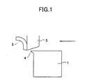
- any of the fixed-type-blade and rotary-blade-type burr removing methods when a stripe-shaped burr 3 formed across the surface of a steel piece 1 is cut along the burr using a cutter 5 as shown in Fig. 1, a protruding burr 4 is formed at an edge of the steel piece 1 although the cut burr 3 is removed to the, outside of the steel piece 1 as a cut chip. Accordingly, a problem of the drop of a yield and the like described above is caused by the protruding burr 4 in the rolling operation carried out thereafter.
- JP-U-4133512 discloses another burr removing apparatus.
- An object of the present invention is to provide a burr removing method by which no protruding burr is formed at the edge of a steel piece from which a burr is removed.
- the burr located at an edge of a steel piece is cut by disposing the cutter having the circular cutting edge such that the flank of the cutter is substantially in parallel with the surface of the steel piece on which the burr exists and the following formula is satisfied with respect to the burr: R / 2 + W / 2 ⁇ ⁇ ⁇ R - W / 2 where W shows the width of the burr, R shows the radius of the cutter, A shows the shortest distance from the center of the cutter to the center line of the width of the burr; and cutting the burr located at the edge of the steel piece by the cutter by relatively moving the cutter toward the outside of the steel piece along the lengthwise direction of the burr.
- a burr can be naturally cut with a different portion of the circular cutting edge without the need of a drive force, whereby the life of the cutter can be increased.
- a burr located at an edge of a steel piece may be cut by disposing the cutter having the circular cutting edge such that the flank of the cutter is substantially in parallel with the surface of the steel piece on which the burr exists and the center of the cutter is located outwardly of the edge of the steel piece which the burr intersects; and cutting the burr located at the edge of the steel piece by relatively moving the cutter perpendicularly to the lengthwise direction of the burr (claim 3).
- the life of the cutter can be increased.
- a protruding burr is formed when a burr located at an edge of a steel pipe is cut by the cutting edge of a cutter through the force applied thereto by the cutter to cause the burr to be pushed out to the outside of the steel piece. Therefore, the occurrence of the protruding burr can be prevented when the burr is cut by the force applied thereto in such a manner that the force is directed inward of the steel piece place of force for pushing out the burr outward from the edge of the steel piece.
- Burr removing methods of the present invention are based on this fundamental principle. Therefore, the present invention relates to methods of removing a burr located at an edge of a steel piece. While the methods of the present invention are applicable to a burr located in the interior of a steel piece, even if the burr is cut by another method, the effect of the present invention is not spoiled.
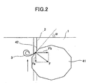
- Fig. 2 schematically shows a burr removing method using a cutter having a polygonal cutting edge (not part of the present invention).
- a cutter 41 having a polygonal cutting edge 42 is disposed such that the flank of the cutter 41 (lower surface of the cutter in the figure) is substantially in parallel with the surface of a steel piece 1 on which a burr 2 exists and the angle a between the polygonal cutting edge 42, which cuts the burr 2, and the edge of the steel piece 1 which intersects the burr 2 is at least 45°. Then, the burr 2 at the edge of the steel piece 1 is cut by moving the cutter 41 toward the outside of the steel piece 1 along the lengthwise direction of the burr 2.
- a press load Fa which is a component force of a cutting reaction force imposed on the polygonal cutting edge 42 and directed toward the outside of the edge of the steel piece 1
- a vertical reaction force Fb whose direction is in parallel with the edge of the steel piece 1. Accordingly, a cut burr 3 is pushed inward of the steel piece 1 in place of outward thereof, and thus no protruding burr is formed.
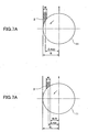
- flank angle (hereafter, referred to as flank angle) between the flank of the cutter 41 and the surface of the steel piece 1 to 1 - 5° as shown in Fig. 3.
- the angle ⁇ (hereinafter referred to as rake angle) between the cutting surface of the cutter 41 and a perpendicular line vertical to the surface of the steel piece 1, is suitably selected in consideration of a cutting resistance and the life of the cutter depending upon an included angle ⁇ .
- the shape of the polygonal cutting edge 42 need not be perfectly polygonal, and the effect of the present invention can be obtained even if the angles of it are rounded or the cutting edge is made somewhat to an arc-shape. In an arc-shaped cutting edge, it is sufficient to set the angle between the tangential line of a circle and the edge of the steel piece which a burr intersects to at least 45°.
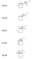
- Fig. 4A - Fig. 4E and Fig. 5A - Fig. 5E schematically show a burr removing method using a cutter having a circular cutting edge as an example of the present invention.
- the press load Fa directed toward the outside of the edge of the steel piece 1 can be made smaller than the vertical reaction force Fb whose direction is in parallel with the edge of the steel piece 1 because the burr 2 is cut with the circular cutting edge which is located at a position spaced apart from the line, which passes through the center of the cutter 11 and is in parallel with the burr 2, by at least R/2 as shown in Fig. 6A.
- R / 2 + W / 2 ⁇ ⁇ ⁇ R - W / 2 Therefore, as shown in Fig.
- the above formula (1) is derived from the positional relationship between the cutter 11 having the circular cutting edge shown in Figs. 7A and 7B and the burr 2. That is, the shortest distance ⁇ from the center of the cutter 11 to the center line of the width of the burr 2 must be less than (R - W/2) to perfectly cut the burr 2 (Fig. 7A). Further, the shortest distance ⁇ must exceed (R/2 + W/2) to cut the burr 2 with the cutting edge located at a position spaced apart from the line, which passes through the center of the cutter 11 and is in parallel with the burr 2, by at least R/2 (Fig. 7B), from which the above formula (1) is derived.
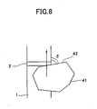
- Fig. 8 schematically shows a burr removing method using a cutter having a polygonal cutting edge (not part of the present invention).
- a cutter 41 having a polygonal cutting edge 42 is disposed such that the flank of the cutter 41 is substantially in parallel, with the surface of a steel piece 1 on which a burr 2 exists and the angle ⁇ between the polygonal cutting edge 42 which cuts the burr 2 and the edge of the steel piece 1 which the burr 2 intersects is 90° or less. Then, the burr 2 at the edge of the steel pipe 1 is cut by moving the cutter 41 so as to be perpendicular to the lengthwise direction of the burr 2.
- the burr 2 is cut in such a manner that the angle ⁇ between the polygonal cutting edge 42 which cuts the burr 2 and the edge of the steel piece 1 which intersects the burr 2 is 90° or less, no protruding burr is formed because the burr 2 at the edge of the steel piece 1 is pushed toward the inside of the steel piece 1.
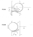
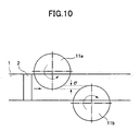
- Fig. 9A - Fig. 9E schematically show a burr removing method using a cutter having a circular cutting edge as another example of the present invention.
- two cutters 11a and 11b each having a circular cutting edge are disposed such that the flanks of the cutters 11a and 11b are substantially in parallel with the surface of a steel piece 1 on which a burr 2 exists and the centers of the cutters 11a and 11b are separately located outwardly of both the edges of the steel piece 1 which the burr 2 intersects, respectively.
- the burr 2 located at both the edges of the steel piece 1 is cut by moving the steel piece 1 so as to be perpendicular to the lengthwise direction of the burr 2.
- the two cutters 11a and 11b are disposed such that the centers thereof are separately located outwardly of both the edges of the steel piece 1 which the burr 2 intersects, respectively, the burr 2 located at both the edges of the steel piece 1 is pushed toward the inside of the steel piece 1. Thus, no protruding burr is formed.
- the burr 2 can be perfectly removed only by the two cutters 11a and 11b.
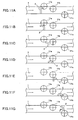
- Fig. 11A - Fig. 11G show a method of using three cutters 11a, 11b and 11c each having a circular cutting edge.
- the burr 2 located at both the edges of the steel piece 1 is removed without the occurrence of a protruding burr by the two cutters 11a and 11c which are disposed such that the centers thereof are separately located outwardly of both the edges of the steel piece 1 which the burr 2 intersects.
- the burr 2 is perfectly removed because the portion of the burr 2 located in the vicinity of the center of the steel piece 1 in the width direction thereof is removed using the cutter 11b disposed between the cutters 11a and tic so as to be overlapped therewith.
- Fig. 12 schematically shows a burr removing apparatus.
- the two cutters 11a and 11b each having the circular cutting edge are disposed to satisfy the above formula (1) with respect to a burr 2 on the surfaces of a steel piece 1 confronting each other and cut the burr 2 of the steel piece 1 by being relatively moved along the lengthwise direction of the burr 2.
- the cutters 11a and 11b are disposed so as to satisfy the above formula (1) with respect to the burr 2 by adjusting the movement of the steel piece 1.
- the steel piece 1 stops and the cutters 11a and 11b simultaneously move from one end of the steel piece 1 to the other end thereof along the lengthwise direction of the burr 2 located on the confronting surfaces of the steel piece 1.
- a burr detecting signal is supplied to a drive control mechanism 60.
- a linearly-moving actuator is actuated which is composed of a fluid pressure cylinder, an electric ball screw or the like, and laterally mounted on a base plate 22 disposed so as to be perpendicular to the steel piece 1 through flanges 27a and 27b.
- a Y-shaped base frame 25 mounted to the distal end of the linearly-moving actuator 26 slides in the direction of the steel piece 1 along cutting guide rails 21a and 21b disposed on the base plate 22.
- the cutters 11a and 11b which are disposed to the distal ends of the Y-shaped base frame 25 through cutter holders 17a and 17b and bearing cases 16a and 16b, approach the burr 2.
- the steel piece 1 is stopped at a position where the cutters 11a and lib satisfy the above formula (1) with respect to the burr 2.
- the cutters 11a and 11b are moved along the lengthwise direction of the burr 2 by the linearly-moving actuator 26, to thereby cut the burr 2. Since the cutters 11a and 11b are disposed so as to satisfy the above formula (1) with respect to the burr 2, the burr 2 located at the edge of the steel piece 1 is cut without the occurrence of a protruding burr.
- the two cutters 11a and 11b are fixed in bearing cases 16a and 16b so that they can be rotated through bearings. Stoppers 15a and 15b on the bearing cases 16a and 16b prevent the removal of the bearings from the bearing cases 16a and 16b. Further, the bearing cases 16a and 16b are fixed to the cutter holders 17a and 17b so as to have a desired clearance angle ⁇ . Chip removing plates 18a and 18b are mounted on the cutter holders 17a and 17b so as to almost in contact with the peripheral surfaces of the cutters 11a and 11b. Since the cutters 11a and 11b can be rotated through the bearings, they can naturally carry out a cutting operation at a different portion of the circular cutting edge without the need of a driving force, whereby the life of the cutters can be increased.
- Fig. 13 schematically shows a burr removing apparatus.
- the two cutters 11a and 11b each having the circular cutting edge are disposed such that the centers of the cutters 11a and 11b are separately located outwardly of both the edges of a steel piece 1 which a burr 2 intersects, and the burr 2 of the steel piece 1 is cut by relatively moving the steel piece 1 so that the two cutters 11a and 11b are perpendicular to the lengthwise direction of the burr 2.
- the two cutters 11a and 11b are previously set such that the centers thereof are separately located outwardly of both the edges of the steel piece 1 which the burr 2 intersects and the positions of the cutters in the width direction of the steel piece 1 is fixed. Therefore, the width of the steel piece 1 from which the burr 2 is cut is always constant.
- the cutters 11a and 11b are lowered and stopped on the surface of the steel piece 1. Then, the burr 2 of the moving steel piece 1 is cut from a direction perpendicular to the lengthwise direction of the burr 2.
- a burr detecting signal is supplied to the drive control mechanism 60. Then, hydraulic cylinders 70 disposed above the steep piece 1 is actuated and the cutters 11a and 11b, which are mounted on the distal ends of the hydraulic cylinders 70 through cutter holders 17a and 17b, are lowered and stopped at the positions on the surface of the steel piece 1 which are suitable for the cut of the burr 2. Since the steel piece 1 is being moved, the burr 2 on the steel piece 1 is cut with the cutters 11a and 11b from a direction perpendicular to the lengthwise direction of the burr 2.
- the cutters 11a and 11b are disposed such that the centers thereof are separately located outwardly of both the edges of the steel piece 1 which the burr 2 intersects, the burr 2 located at the edges of the steel piece 1 is cut without the occurrence of a protruding burr.
- Oil is pumped from an oil tank 73 by an oil pump 72 and supplied to the hydraulic cylinders 70 through hydraulic pipes 71.
Landscapes
- Engineering & Computer Science (AREA)
- Mechanical Engineering (AREA)
- Optics & Photonics (AREA)
- Physics & Mathematics (AREA)
- Milling Processes (AREA)
- Milling, Broaching, Filing, Reaming, And Others (AREA)
- Finish Polishing, Edge Sharpening, And Grinding By Specific Grinding Devices (AREA)
- Gear Processing (AREA)
- Metal Rolling (AREA)
- Processing And Handling Of Plastics And Other Materials For Molding In General (AREA)
- Mechanical Treatment Of Semiconductor (AREA)
- Sawing (AREA)
- Diaphragms For Electromechanical Transducers (AREA)
- Glass Compositions (AREA)
Claims (5)
- Verfahren zum Entfernen von Graten, umfassend die folgenden Schritte: Anordnen einer Schneidvorrichtung (11) mit einer kreisförmigen Schneidkante, so dass die Flanke der Schneidvorrichtung (11) im Wesentlichen parallel zur Oberfläche eines Stahlstücks (1) liegt, auf welchem sich ein Grat (2) befindet, dadurch gekennzeichnet, dass die folgende Formel in Bezug auf den Grat (2) erfüllt ist:

Wobei W die Breite des Grats (2) zeigt, R den Radius der Schneidvorrichtung (11) zeigt, und Δ den kürzesten Abstand von der Mitte der Schneidvorrichtung zur Mittellinie der Breite des Grates zeigt; und Schneiden des Grates (2), der an einer Kante des Stahlstücks (1) platziert ist, mit Hilfe der Schneidvorrichtung (41), indem die Schneidvorrichtung (41) relativ entlang der Längsrichtung des Grats (2) zur Außenseite des Stahlstücks (1) hin bewegt wird. - Verfahren nach Anspruch 1, wobei zwei Schneidvorrichtungen (11a, 11b) vorgesehen sind, wobei jede eine kreisförmige Schneidkante aufweist, und die dazu veranlasst werden, sich mittels eines Antriebskontrollmechanismus (60) einem Grat (2) als Reaktion auf ein Grat-Erfassungssignal anzunähern, das von einem Grat-Erfassungsgerät (50) ausgegeben wird, und die so angeordnet sind, dass die Formel (1) in Bezug auf den Grat (2) erfüllt ist, und dann entlang der Längsrichtung des Grats (2) bewegt werden, wobei die beiden Schneidvorrichtungen (11a, 11b) quer zum Stahlstück (1) angeordnet sind.
- Verfahren zum Entfernen von Graten, umfassend die Schritte des Anordnens einer Schneidvorrichtung (11) mit einer kreisförmigen Schneidkante, so dass die Flanke der Schneidvorrichtung (11) im Wesentlichen parallel zur Oberfläche eines Stahlstücks (1) liegt, auf welchem sich ein Grat (2) befindet, und die Mitte der Schneidvorrichtung (11) außerhalb der Kante des Stahlstücks (1) platziert ist, die der Grat (2) schneidet; gekennzeichnet durch das Schneiden des Grats (2), der sich an einer Kante des Stahlstücks (1) befindet, in dem die Schneidvorrichtung (11) senkrecht zur Längsrichtung des Grats (2) relativ bewegt wird.
- Verfahren nach Anspruch 3, wobei mindestens zwei Schneidvorrichtungen (11a-c) vorgesehen sind, von denen zwei eine kreisförmige Schneidkante aufweisen und jeweils so angeordnet sind, dass ihre Mitte außerhalb einer der beiden Kanten des Stahlstücks (1) platziert ist, die der Grat (2) schneidet, und wobei die mindestens zwei Schneidvorrichtungen (11a-c) veranlasst werden, sich mittels eines Antriebskontrollmechanismus (60) dem Grat (2) als Reaktion auf ein Grat-Erfassungssignal, das von einer Grat-Erfassungsvorrichtung (50) ausgesandt wird, anzunähern.
- Verfahren nach einem der Ansprüche 1 bis 4, wobei eine drehbare Schneidvorrichtung (11) mit einer kreisförmigen Schneidkante verwendet wird.
Applications Claiming Priority (5)
| Application Number | Priority Date | Filing Date | Title |
|---|---|---|---|
| JP33233898 | 1998-11-24 | ||
| JP33233898 | 1998-11-24 | ||
| JP36384398 | 1998-12-22 | ||
| JP36384398 | 1998-12-22 | ||
| EP19990952800 EP1057563B1 (de) | 1998-11-24 | 1999-10-28 | Methode und gerät zum entgraten |
Related Parent Applications (2)
| Application Number | Title | Priority Date | Filing Date |
|---|---|---|---|
| EP19990952800 Division EP1057563B1 (de) | 1998-11-24 | 1999-10-28 | Methode und gerät zum entgraten |
| EP99952800.3 Division | 1999-10-28 |
Publications (3)
| Publication Number | Publication Date |
|---|---|
| EP1464429A2 EP1464429A2 (de) | 2004-10-06 |
| EP1464429A3 EP1464429A3 (de) | 2004-10-20 |
| EP1464429B1 true EP1464429B1 (de) | 2006-12-13 |
Family
ID=26574166
Family Applications (2)
| Application Number | Title | Priority Date | Filing Date |
|---|---|---|---|
| EP20040011584 Expired - Lifetime EP1464429B1 (de) | 1998-11-24 | 1999-10-28 | Entgratverfahren |
| EP19990952800 Expired - Lifetime EP1057563B1 (de) | 1998-11-24 | 1999-10-28 | Methode und gerät zum entgraten |
Family Applications After (1)
| Application Number | Title | Priority Date | Filing Date |
|---|---|---|---|
| EP19990952800 Expired - Lifetime EP1057563B1 (de) | 1998-11-24 | 1999-10-28 | Methode und gerät zum entgraten |
Country Status (8)
| Country | Link |
|---|---|
| US (4) | US6296428B1 (de) |
| EP (2) | EP1464429B1 (de) |
| JP (1) | JP3721507B2 (de) |
| KR (1) | KR100381613B1 (de) |
| AT (2) | ATE347960T1 (de) |
| DE (2) | DE69922793T2 (de) |
| ES (2) | ES2235531T3 (de) |
| WO (1) | WO2000030794A1 (de) |
Families Citing this family (23)
| Publication number | Priority date | Publication date | Assignee | Title |
|---|---|---|---|---|
| US7175376B2 (en) * | 2001-04-27 | 2007-02-13 | Thk Co., Ltd. | Method of cutting long-sized hardened steel material and cutting device |
| MY142017A (en) | 2004-03-19 | 2010-08-16 | Nestec Sa | Composition comprising all essential nutrients of a fruit or a plant material with increased stability and bioavailability and process of forming the same |
| EP1728503B1 (de) | 2005-06-02 | 2008-09-17 | KPSS-Kao Professional Salon Services GmbH | Haarkonditionierende kosmetische Zusammensetzung |
| EP1728502A1 (de) * | 2005-06-02 | 2006-12-06 | KPSS Kao Professional Salon Services GmbH | Kosmetische Zusammensetzung |
| JP2006341276A (ja) | 2005-06-09 | 2006-12-21 | Jp Steel Plantech Co | 連続圧延方法及び連続圧延設備 |
| US20100119321A1 (en) * | 2006-12-22 | 2010-05-13 | Tingley Iii William Q | Method and apparatus for controlled-fracture machining |
| CA2710500A1 (en) * | 2006-12-22 | 2008-07-03 | Tennine Corp. | Method and apparatus for non-rotary machining |
| US8821086B2 (en) | 2006-12-22 | 2014-09-02 | Tennine Corporation | Method and apparatus for controlled-fracture machining |
| US8034282B2 (en) * | 2008-09-05 | 2011-10-11 | Kennametal Inc. | Thermal energy machine with interchangeable components for processing different sized parts |
| EP2181816B1 (de) * | 2008-11-03 | 2012-01-04 | Brandt Kantentechnik GmbH | Bearbeitungsaggregat |
| JP5534509B2 (ja) * | 2010-02-03 | 2014-07-02 | オークマ株式会社 | 切削加工方法 |
| CN103038039B (zh) * | 2010-08-09 | 2015-01-21 | 日本省力机械株式会社 | 刮板式去毛刺装置 |
| JP5911714B2 (ja) * | 2011-12-07 | 2016-04-27 | 株式会社ディスコ | 分割方法 |
| ES2633133T3 (es) * | 2012-10-12 | 2017-09-19 | Primetals Technologies Austria GmbH | Aparato de desbarbado con medios de accionamiento para accionar de manera rotatoria y reversible el aparato hacia y alejándose de un lingote |
| DE102012021275B4 (de) * | 2012-10-29 | 2014-05-15 | Audi Ag | Verfahren zum Planbearbeiten von Oberflächen an Werkstücken |
| ES2702154T3 (es) * | 2013-10-11 | 2019-02-27 | Nihon Shoryoku Kikai Co Ltd | Cuchilla de cortador y dispositivo de procesamiento |
| US9101991B1 (en) | 2014-07-17 | 2015-08-11 | Tennine Corp. | Method and apparatus for non-spindle multi-axis machining |
| CN106142481A (zh) | 2015-01-31 | 2016-11-23 | 侊桐Plant | 铸件产品用毛刺和浇口去除装置 |
| KR102076490B1 (ko) | 2017-04-07 | 2020-02-13 | 한국기계연구원 | 버어 제거가 가능한 성형 장치 |
| IT201800011008A1 (it) * | 2018-12-12 | 2020-06-12 | Danieli Off Mecc | Dispositivo per la pulitura di bave di saldatura di barre metalliche e relativo metodo di pulitura di bave |
| CN111823016B (zh) * | 2020-06-24 | 2021-10-12 | 上海浦永金属制品有限公司 | 一种制造不锈钢焊管的生产线 |
| WO2023116621A1 (en) | 2021-12-20 | 2023-06-29 | Societe Des Produits Nestle S.A. | Process for preparing a berry composition |
| EP4335562A1 (de) * | 2022-09-08 | 2024-03-13 | David Teng Pong | Flash-schweissen für knüppel mit heruntergeschnittenen knüppelenden |
Family Cites Families (35)
| Publication number | Priority date | Publication date | Assignee | Title |
|---|---|---|---|---|
| US1995104A (en) * | 1933-08-16 | 1935-03-19 | Henry E Morton | Reciprocable ram flash removing machine |
| US2202910A (en) | 1938-06-23 | 1940-06-04 | Mesta Machine Co | Trimming machine |
| US2273624A (en) * | 1939-07-17 | 1942-02-17 | Mclouth Steel Corp | Apparatus for removing weld flash from sheet metal |
| US2592640A (en) * | 1949-05-03 | 1952-04-15 | Bailis Reuben | Flash removing apparatus |
| US3040632A (en) | 1955-05-10 | 1962-06-26 | Gray & Co G A | Double action cutting tool |
| US2936679A (en) * | 1956-07-02 | 1960-05-17 | Giddings & Lewis | Method for cutting metal |
| US2959842A (en) | 1957-12-06 | 1960-11-15 | Bundy Tubing Co | Tube scarfing device |
| US3398613A (en) * | 1966-02-04 | 1968-08-27 | Elektro Thermit Gmbh | Apparatus for removing excess welding material from rail welds |
| US3952630A (en) * | 1973-11-12 | 1976-04-27 | Grotnes Machine Works, Inc. | Truck rim edge milling apparatus |
| JPS5142040A (ja) | 1974-10-09 | 1976-04-09 | Mitsubishi Electric Corp | Yosetsubuseikeisochi |
| JPS5243754A (en) | 1975-10-03 | 1977-04-06 | Nippon Kokan Kk | Completely continuous steel rolling method |
| JPS53147649A (en) | 1977-05-30 | 1978-12-22 | Mitsubishi Electric Corp | Apparatus for removing fin |
| JPS58151971A (ja) | 1982-03-05 | 1983-09-09 | Kawasaki Steel Corp | 熱間圧延材のオンライン接合装置 |
| JPS59176711A (ja) | 1983-03-25 | 1984-10-06 | Matsushita Electric Ind Co Ltd | レンズ移動装置 |
| AT381891B (de) | 1983-10-13 | 1986-12-10 | Voest Alpine Ag | Vorrichtung zum entgraten von werkstuecken |
| JPS60242912A (ja) * | 1984-05-17 | 1985-12-02 | Mitsubishi Heavy Ind Ltd | バリ除去方法 |
| JPS6130287A (ja) | 1984-07-19 | 1986-02-12 | Mitsubishi Electric Corp | フラツシユ溶接装置 |
| JPS61199312A (ja) | 1985-02-28 | 1986-09-03 | Matsushita Electric Ind Co Ltd | セラミツク発振子 |
| JPS61214908A (ja) * | 1985-03-20 | 1986-09-24 | Kawasaki Steel Corp | かえり取り装置 |
| DE3515111A1 (de) * | 1985-04-26 | 1986-11-06 | Bwg Bergwerk- Und Walzwerk-Maschinenbau Gmbh, 4100 Duisburg | Verfahren und vorrichtung zum entfernen von brennbaerten an brennschneidkanten von metallteilen, insbesondere brammen, bloecken, knueppeln oder dergleichen |
| DE3526950C1 (de) * | 1985-07-27 | 1986-08-28 | Dr. techn. Ernst Linsinger & Co GmbH, Steyrermühl | Fräseinrichtung zum Bearbeiten der Kanten von Blechplatten oder Blechbändern |
| US4859126A (en) | 1986-02-21 | 1989-08-22 | Keibler-Thompson Corp. | Apparatus and method for removing dross ridges from a metal workpiece |
| DE3640522A1 (de) * | 1986-02-24 | 1987-08-27 | Linsinger Ernst & Co Gmbh | Umfangfraeser zum bearbeiten der kanten von blechen |
| DE3618224A1 (de) * | 1986-05-30 | 1987-12-03 | Hoesch Ag | Verfahren und vorrichtung zum laengsentgraten von profilen |
| US5192175A (en) * | 1988-07-06 | 1993-03-09 | Hitachi, Ltd. | Burr trimming method and apparatus for machining shock testing pieces, and automatic machining system thereof |
| JPH02107416A (ja) | 1988-10-17 | 1990-04-19 | Three Bond Co Ltd | 複合物品の成形方法 |
| JPH02107416U (de) * | 1989-02-10 | 1990-08-27 | ||
| JPH04178273A (ja) | 1989-12-06 | 1992-06-25 | Hitachi Ltd | フラツシユバツト溶接機のビードトリミング装置 |
| EP0463201A1 (de) | 1990-06-25 | 1992-01-02 | AUTE Gesellschaft für autogene Technik mbH | Stahlstranggiessanlage mit mechanischer Entfernungseinrichtung für Sauerstoffschneidbärte |
| JP2648388B2 (ja) | 1990-09-25 | 1997-08-27 | 三菱電機株式会社 | パルス発生回路 |
| JPH04133512U (ja) * | 1991-05-31 | 1992-12-11 | 川崎製鉄株式会社 | ストリツプ端面のばり取り装置 |
| TW221703B (de) | 1992-03-04 | 1994-03-11 | Boc Group Inc | |
| JPH063523U (ja) * | 1992-06-16 | 1994-01-18 | 三菱重工業株式会社 | ばりの除去装置 |
| ES2116248T3 (es) | 1996-10-26 | 2000-09-01 | Lotz H K Feuerschutzbaustoffe | Dispositivo y herramienta para la eliminacion de rebabas en instalaciones de colada continua. |
| US6067880A (en) | 1996-12-03 | 2000-05-30 | Arrigoni; John P. | Deburring device |
-
1999
- 1999-10-28 EP EP20040011584 patent/EP1464429B1/de not_active Expired - Lifetime
- 1999-10-28 ES ES99952800T patent/ES2235531T3/es not_active Expired - Lifetime
- 1999-10-28 DE DE1999622793 patent/DE69922793T2/de not_active Expired - Lifetime
- 1999-10-28 JP JP2000583662A patent/JP3721507B2/ja not_active Expired - Lifetime
- 1999-10-28 ES ES04011584T patent/ES2274344T3/es not_active Expired - Lifetime
- 1999-10-28 DE DE1999634444 patent/DE69934444T2/de not_active Expired - Lifetime
- 1999-10-28 AT AT04011584T patent/ATE347960T1/de active
- 1999-10-28 EP EP19990952800 patent/EP1057563B1/de not_active Expired - Lifetime
- 1999-10-28 WO PCT/JP1999/005971 patent/WO2000030794A1/ja not_active Ceased
- 1999-10-28 AT AT99952800T patent/ATE285309T1/de active
- 1999-10-28 KR KR10-2000-7005023A patent/KR100381613B1/ko not_active Expired - Lifetime
-
2000
- 2000-06-16 US US09/595,226 patent/US6296428B1/en not_active Expired - Lifetime
-
2001
- 2001-05-24 US US09/864,448 patent/US6402441B2/en not_active Expired - Lifetime
- 2001-12-03 US US10/006,947 patent/US20020061237A1/en not_active Abandoned
-
2003
- 2003-02-21 US US10/371,433 patent/US6648564B2/en not_active Expired - Lifetime
Also Published As
| Publication number | Publication date |
|---|---|
| KR100381613B1 (ko) | 2003-04-26 |
| EP1057563A1 (de) | 2000-12-06 |
| ES2235531T3 (es) | 2005-07-01 |
| US6648564B2 (en) | 2003-11-18 |
| US6296428B1 (en) | 2001-10-02 |
| ATE347960T1 (de) | 2007-01-15 |
| ATE285309T1 (de) | 2005-01-15 |
| US20030129034A1 (en) | 2003-07-10 |
| EP1464429A3 (de) | 2004-10-20 |
| US20020061237A1 (en) | 2002-05-23 |
| KR20010031921A (ko) | 2001-04-16 |
| DE69922793D1 (de) | 2005-01-27 |
| JP3721507B2 (ja) | 2005-11-30 |
| ES2274344T3 (es) | 2007-05-16 |
| US20010022921A1 (en) | 2001-09-20 |
| EP1057563B1 (de) | 2004-12-22 |
| DE69922793T2 (de) | 2005-12-15 |
| DE69934444T2 (de) | 2007-10-31 |
| WO2000030794A1 (en) | 2000-06-02 |
| US6402441B2 (en) | 2002-06-11 |
| DE69934444D1 (de) | 2007-01-25 |
| EP1057563A4 (de) | 2002-02-06 |
| EP1464429A2 (de) | 2004-10-06 |
Similar Documents
| Publication | Publication Date | Title |
|---|---|---|
| EP1464429B1 (de) | Entgratverfahren | |
| US4840303A (en) | Method and apparatus for cutting and welding steel strips | |
| US4854493A (en) | Method and apparatus for cutting welding steel strips | |
| JPWO2000030794A1 (ja) | バリ取り方法およびその装置 | |
| CN116408580B (zh) | 一种开放式管道全位置焊接装置 | |
| JP4749617B2 (ja) | ストリップ接続装置 | |
| US4721241A (en) | Welding apparatus assembled together with grinding device | |
| US4597521A (en) | Rotary notcher for a joined metallic strip | |
| US4850522A (en) | Steel strip splicing station | |
| KR100624241B1 (ko) | 박판 용접 방법 및 장치 | |
| JP3397922B2 (ja) | 移動鋼板の接合方法および装置 | |
| JP2000107864A (ja) | フラッシュバット溶接方法およびスパッタ除去装置を持つフラッシュバット溶接装置 | |
| JP2948843B2 (ja) | 鋼帯等の溶接部余盛の除去装置 | |
| JP4692350B2 (ja) | 鋼板の端面機械加工方法及び装置 | |
| KR100393891B1 (ko) | 전극 로울러시스템을 이용한 테일러드웰디드블랭크 판의 제조방법 | |
| JPS6228096A (ja) | レ−ザ溶接時の金属ストリツプの突合わせ方法 | |
| WO2022266750A1 (en) | Method and system for repairing rail wheels | |
| KR20030023106A (ko) | 강판용접기의 강판에지부 클리핑장치 | |
| JP2831141B2 (ja) | 圧延材の給電クランプ装置 | |
| KR20010058174A (ko) | 매쉬시임 용접장치의 클램프구조 | |
| JPH11138356A (ja) | 圧延材の走間接合方法及び装置 | |
| JPS63165087A (ja) | レ−ザ溶断溶接装置 | |
| JPH09141485A (ja) | 溶接鋼管の内面切削ビード処理装置 | |
| JPH07290110A (ja) | 連続熱間圧延におけるシートバー接合保持装置 | |
| JPH08252608A (ja) | 圧接接合設備 |
Legal Events
| Date | Code | Title | Description |
|---|---|---|---|
| PUAI | Public reference made under article 153(3) epc to a published international application that has entered the european phase |
Free format text: ORIGINAL CODE: 0009012 |
|
| PUAL | Search report despatched |
Free format text: ORIGINAL CODE: 0009013 |
|
| 17P | Request for examination filed |
Effective date: 20040514 |
|
| AC | Divisional application: reference to earlier application |
Ref document number: 1057563 Country of ref document: EP Kind code of ref document: P |
|
| AK | Designated contracting states |
Kind code of ref document: A2 Designated state(s): AT BE CH CY DE DK ES FI FR GB GR IE IT LI LU MC NL PT SE |
|
| AK | Designated contracting states |
Kind code of ref document: A3 Designated state(s): AT BE CH CY DE DK ES FI FR GB GR IE IT LI LU MC NL PT SE |
|
| RAP1 | Party data changed (applicant data changed or rights of an application transferred) |
Owner name: JP STEEL PLANTECH CO. |
|
| AKX | Designation fees paid |
Designated state(s): AT BE CH CY DE DK ES FI FR GB GR IE IT LI LU MC NL PT SE |
|
| GRAP | Despatch of communication of intention to grant a patent |
Free format text: ORIGINAL CODE: EPIDOSNIGR1 |
|
| RIN1 | Information on inventor provided before grant (corrected) |
Inventor name: YAMASHITA, KOJI Inventor name: OKUSHIMA, KOJI Inventor name: HAYASHI, HIROMASA Inventor name: OKAWA, SUSUMU |
|
| GRAS | Grant fee paid |
Free format text: ORIGINAL CODE: EPIDOSNIGR3 |
|
| GRAA | (expected) grant |
Free format text: ORIGINAL CODE: 0009210 |
|
| AC | Divisional application: reference to earlier application |
Ref document number: 1057563 Country of ref document: EP Kind code of ref document: P |
|
| AK | Designated contracting states |
Kind code of ref document: B1 Designated state(s): AT DE ES FI FR GB IT SE |
|
| REG | Reference to a national code |
Ref country code: GB Ref legal event code: FG4D |
|
| REF | Corresponds to: |
Ref document number: 69934444 Country of ref document: DE Date of ref document: 20070125 Kind code of ref document: P |
|
| REG | Reference to a national code |
Ref country code: SE Ref legal event code: TRGR |
|
| REG | Reference to a national code |
Ref country code: ES Ref legal event code: FG2A Ref document number: 2274344 Country of ref document: ES Kind code of ref document: T3 |
|
| ET | Fr: translation filed | ||
| PLBE | No opposition filed within time limit |
Free format text: ORIGINAL CODE: 0009261 |
|
| STAA | Information on the status of an ep patent application or granted ep patent |
Free format text: STATUS: NO OPPOSITION FILED WITHIN TIME LIMIT |
|
| 26N | No opposition filed |
Effective date: 20070914 |
|
| REG | Reference to a national code |
Ref country code: FR Ref legal event code: PLFP Year of fee payment: 18 |
|
| REG | Reference to a national code |
Ref country code: FR Ref legal event code: PLFP Year of fee payment: 19 |
|
| REG | Reference to a national code |
Ref country code: FR Ref legal event code: PLFP Year of fee payment: 20 |
|
| PGFP | Annual fee paid to national office [announced via postgrant information from national office to epo] |
Ref country code: FR Payment date: 20180913 Year of fee payment: 20 |
|
| PGFP | Annual fee paid to national office [announced via postgrant information from national office to epo] |
Ref country code: DE Payment date: 20181016 Year of fee payment: 20 Ref country code: AT Payment date: 20180925 Year of fee payment: 20 Ref country code: SE Payment date: 20181011 Year of fee payment: 20 Ref country code: FI Payment date: 20181009 Year of fee payment: 20 |
|
| PGFP | Annual fee paid to national office [announced via postgrant information from national office to epo] |
Ref country code: GB Payment date: 20181024 Year of fee payment: 20 Ref country code: IT Payment date: 20181018 Year of fee payment: 20 Ref country code: ES Payment date: 20181105 Year of fee payment: 20 |
|
| REG | Reference to a national code |
Ref country code: DE Ref legal event code: R071 Ref document number: 69934444 Country of ref document: DE |
|
| REG | Reference to a national code |
Ref country code: GB Ref legal event code: PE20 Expiry date: 20191027 |
|
| REG | Reference to a national code |
Ref country code: SE Ref legal event code: EUG |
|
| REG | Reference to a national code |
Ref country code: AT Ref legal event code: MK07 Ref document number: 347960 Country of ref document: AT Kind code of ref document: T Effective date: 20191028 |
|
| PG25 | Lapsed in a contracting state [announced via postgrant information from national office to epo] |
Ref country code: GB Free format text: LAPSE BECAUSE OF EXPIRATION OF PROTECTION Effective date: 20191027 |
|
| REG | Reference to a national code |
Ref country code: ES Ref legal event code: FD2A Effective date: 20220126 |
|
| PG25 | Lapsed in a contracting state [announced via postgrant information from national office to epo] |
Ref country code: ES Free format text: LAPSE BECAUSE OF EXPIRATION OF PROTECTION Effective date: 20191029 |