EP1460232B1 - Bodendichtung in einem Türblatt - Google Patents
Bodendichtung in einem Türblatt Download PDFInfo
- Publication number
- EP1460232B1 EP1460232B1 EP04003220A EP04003220A EP1460232B1 EP 1460232 B1 EP1460232 B1 EP 1460232B1 EP 04003220 A EP04003220 A EP 04003220A EP 04003220 A EP04003220 A EP 04003220A EP 1460232 B1 EP1460232 B1 EP 1460232B1
- Authority
- EP
- European Patent Office
- Prior art keywords
- arms
- groove
- sealing
- profile
- profile rail
- Prior art date
- Legal status (The legal status is an assumption and is not a legal conclusion. Google has not performed a legal analysis and makes no representation as to the accuracy of the status listed.)
- Expired - Lifetime
Links
Images

Classifications
-
- E—FIXED CONSTRUCTIONS
- E06—DOORS, WINDOWS, SHUTTERS, OR ROLLER BLINDS IN GENERAL; LADDERS
- E06B—FIXED OR MOVABLE CLOSURES FOR OPENINGS IN BUILDINGS, VEHICLES, FENCES OR LIKE ENCLOSURES IN GENERAL, e.g. DOORS, WINDOWS, BLINDS, GATES
- E06B7/00—Special arrangements or measures in connection with doors or windows
- E06B7/16—Sealing arrangements on wings or parts co-operating with the wings
- E06B7/18—Sealing arrangements on wings or parts co-operating with the wings by means of movable edgings, e.g. draught sealings additionally used for bolting, e.g. by spring force or with operating lever
- E06B7/20—Sealing arrangements on wings or parts co-operating with the wings by means of movable edgings, e.g. draught sealings additionally used for bolting, e.g. by spring force or with operating lever automatically withdrawn when the wing is opened, e.g. by means of magnetic attraction, a pin or an inclined surface, especially for sills
- E06B7/215—Sealing arrangements on wings or parts co-operating with the wings by means of movable edgings, e.g. draught sealings additionally used for bolting, e.g. by spring force or with operating lever automatically withdrawn when the wing is opened, e.g. by means of magnetic attraction, a pin or an inclined surface, especially for sills with sealing strip being moved to a retracted position by elastic means, e.g. springs
-
- E—FIXED CONSTRUCTIONS
- E06—DOORS, WINDOWS, SHUTTERS, OR ROLLER BLINDS IN GENERAL; LADDERS
- E06B—FIXED OR MOVABLE CLOSURES FOR OPENINGS IN BUILDINGS, VEHICLES, FENCES OR LIKE ENCLOSURES IN GENERAL, e.g. DOORS, WINDOWS, BLINDS, GATES
- E06B7/00—Special arrangements or measures in connection with doors or windows
- E06B7/16—Sealing arrangements on wings or parts co-operating with the wings
- E06B7/18—Sealing arrangements on wings or parts co-operating with the wings by means of movable edgings, e.g. draught sealings additionally used for bolting, e.g. by spring force or with operating lever
- E06B7/20—Sealing arrangements on wings or parts co-operating with the wings by means of movable edgings, e.g. draught sealings additionally used for bolting, e.g. by spring force or with operating lever automatically withdrawn when the wing is opened, e.g. by means of magnetic attraction, a pin or an inclined surface, especially for sills
Definitions
- the invention relates to a bottom seal in a door leaf, with a substantially U-shaped rail, which is movable in a groove in the bottom of the door leaf by means of a mechanism actuated when closing the door from a retracted upward rest position against spring force in a lowered sealing position , and at least one sealing element of elastic material fastened to the rail, which has on its underside a bottom sealing section and laterally thereto adjoining legs extending substantially parallel to the vertical side walls of the groove.
- Such a door bottom seal is known for example from EP 1 162 341 A1.
- the one-piece sealing element engages with its vertical legs a mounted in the groove mounting profile, which in turn leads in its interior, the profile carrying the sealing profile rail and enclosing it moving mechanism.
- the outside Legs of the sealing element bearing against the installation profile prevent the passage of sound between the installation profile and the profile rail, while the connection path between the side walls of the groove and the installation profile - past the sealing element - is interrupted by the mounting of the installation profile in the groove base.
- This design of the door base gasket causes a sliding of the legs of the sealing element in each sealing process, over the entire lowering and return stroke of the rail with the sealing element when closing and when opening the door.
- the result is a correspondingly high wear and a decrease in the sealing effect;
- the closing and opening forces are greater, the higher the system pressure of the legs of the sealing element is selected on the mounting profile to achieve a good seal.
- the upper edge strips of the two U-legs of the rail are each bent at an acute angle outwards and the free ends of the legs of the sealing element in the rest position of the rail at the beginning the bend of their legs are, and if in the sealing position of the rail of the bottom sealing portion of the sealing or each Abêtlements is compressed, so that thereby upwardly moving free ends of the legs of the sealing of the angled edge strips of the legs of the rail in abutment against the side walls the groove are pressed.
- a substantially inverted U-shaped, attachable to the groove base mounting profile serves as an abutment for the mechanics and the free ends of them only Form over a part of the groove depth and adjacent to the side walls of the groove legs form stops for the edge strips of the legs of the rail.
- the return stroke of the profile rail is defined with the sealing element / the sealing elements defined. It is particularly provided that the edge portions of the free ends of the legs of the mounting profile are bent inward, which improves the security against attack.
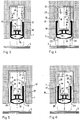
- the bottom seal designated as a whole by 4 as illustrated in FIG. 2 for the bottom seal located in FIG. 1 in its rest position.
- the bottom seal 4 consists of a mounting profile 5, the first leg 6 extend from the groove bottom 7 only over part of the vertical depth of the groove 2. Edge portions 8 of the free ends of the first leg 6 of the mounting profile 5 are bent inwardly.
- the movable part of the bottom seal consists of a profile rail 9, which as well as the installation profile 5 passes over the entire length of the groove 2 and thus the entire width of the door panel 1.
- the latter also applies to the sealing element 10 made of elastic material, which is held with its substantially T-shaped projection 11 in the section 12 of the rail 9.
- Integrally formed on the T-neck 11 is the bottom sealing portion 13 of the sealing element 10, which can be relatively strong einfedem as a result of its hollow chamber configuration when the rail 9 is pressed with the sealing member 10 against the bottom 3, which, as usual, with the help of only indicated by dashed lines mechanism 144th is effected when the closing of the door is actuated from its front side.
- the rail 9 has second legs 15, the upper edge strips 16 are angled in the figures 1 and 2 removable manner outwards.
- the free ends 17 of the third legs 18 of the sealing element 10 are located at the bending line of the edge strips 16. If the bottom sealing section 13 of the sealing element 10 is then compressed in the manner shown in FIG. 2, the free ends 17 move the third leg 18 of the sealing member 10 upwards and are - pushed to the edge strip 16 of the rail sliding outwardly into abutment against the side walls 19 of the groove 2.
- FIG. 2 shows this sealing position.
- FIG. 1a shows the bottom seal of FIG. 1 with two sealing elements 10a and 10b, each of which has a bottom sealing section 13 but only a third leg 18.
- Each sealing element 10a, 10b has a round strip projection 11a, which are held in correspondingly shaped sections 12a of the profiled rail 12.
- This two-part sealing element design can also be used in the embodiments explained below.
- edge portions 8 of the first leg 6 of the mounting profile 5 is not as stops to define the rest position, but this task is taken over by the lateral projections 22 of the web 21 of the mounting profile 5.
- the dotted lines 25 indicate the maximum width (diameter) of drive rods for locking a double door panel.
- the embodiment of Figure 5 corresponds to those of Figures 1 to 3.
- the first leg 6 of the mounting profile 5 are extended downward and dress with their extensions in 23, the side walls 19 of the groove 2 in its lower portions.
- the function of the offsets 8 of the first legs 6 in the embodiment of Figures 1 to 3 is taken over by strip-shaped projections 24 on the extended first legs 6 of the mounting profile.
- the embodiment according to FIG. 6 essentially corresponds to that of FIG. 5. Only the strip-like projections 24 are displaced further upwards towards the web 21 of the installation profile because the second legs 15 of the profile rail 9 with the adjoining edge strips 16 again extend 20 which, as in the embodiment of Figure 4 increase the moment of resistance of the rail 9.
Landscapes
- Engineering & Computer Science (AREA)
- Civil Engineering (AREA)
- Structural Engineering (AREA)
- Specific Sealing Or Ventilating Devices For Doors And Windows (AREA)
- Seal Device For Vehicle (AREA)
Description
- Die Erfindung betrifft eine Bodendichtung in einem Türblatt, mit einer im Wesentlichen U-förmigen Profilschiene, die in einer Nut in der Unterseite des Türblatts mit Hilfe einer beim Schließen der Tür betätigten Mechanik aus einer nach oben zurückgezogenen Ruhestellung gegen Federkraft in eine abgesenkte Dichtstellung bewegbar ist, und mit mindestens einem an der Schiene befestigten Abdichtelement aus elastischem Material, welches unterseitig einen Bodendichtabschnitt und seitlich daran ansetzende, sich im Wesentlichen parallel zu den vertikalen Seitenwänden der Nut nach oben erstreckende Schenkel hat.
- Eine solche Türbodendichtung ist beispielsweise aus der EP 1 162 341 A1 bekannt. Dort umgreift das einstückige Abdichtelement mit seinen vertikalen Schenkeln ein in der Nut befestigtes Einbauprofil, welches seinerseits in seinem Innenraum die das Abdichtprofil tragende Profilschiene führt und die sie bewegende Mechanik umschließt. Die außen am Einbauprofil anliegenden Schenkel des Abdichtelements verhindern den Schalldurchtritt zwischen Einbauprofil und Profilschiene, während der Verbindungspfad zwischen den Seitenwänden der Nut und dem Einbauprofil - vorbei am Abdichtelement - durch die Befestigung des Einbauprofils im Nutengrund unterbrochen ist.
- Diese Ausbildung der Türbodendichtung bedingt ein Gleiten der Schenkel des Abdichtelements bei jedem Dichtvorgang, und zwar über den gesamten Absenk- und Rückkehrhub der Profilschiene mit dem Abdichtelement beim Schließen und beim Öffnen der Tür. Die Folge ist ein entsprechend hoher Verschleiß und ein Nachlassen der Dichtwirkung; auch werden die Schließ- und Öffnungskräfte umso größer, je höher der Anlagedruck der Schenkel des Abdichtelements am Einbauprofil zur Erzielung einer guten Abdichtung gewählt wird.
- Es wurde nun gefunden, dass die Reibungsverluste hinsichtlich Kraftaufwand und Verschleiß entscheidend verringert werden können, wenn erfindungsgemäß die oberen Randstreifen der beiden U-Schenkel der Profilschiene jeweils nach außen spitzwinklig abgebogen sind und die freien Enden der Schenkel des Abdichtelements in der Ruhestellung der Profilschiene am Anfang der Abbiegung ihrer Schenkel liegen, und wenn in der Dichtstellung der Profilschiene der Bodendichtabschnitt des Abdichtelements bzw. jedes Abdichtelements eingefedert ist, so dass die dadurch nach oben bewegten freien Enden der Schenkel des Abdichtelements von den abgewinkelten Randstreifen der Schenkel der Profilschiene in Anlage an die Seitenwände der Nut gedrückt sind. Auf diese Weise kommt es dann nur auf dem letzten Hubabschnitt des Abdichtvorganges zur gleitenden Bewegung der freien Schenkelenden des Abdichtelements (oder der Abdichtelemente) an den abgewinkelten Randstreifen der U-Schenkel der Profilschiene, wodurch sich die freien Enden der Abdichtelement-Schenkel an die Seitenwände der Nut anlegen, ohne daran zu gleiten.
- Letzteres ist die nachteilige Folge der aus der EP 0 338 942 A2 bekannten Dichtanordnung, bei der die Schenkel des Dichtprofils unter inhärenter Vorspannung ständig an die Innenwände eines die Nut im Türblatt auskleidenden Einbauprofils angedrückt sind und demzufolge über den gesamten Arbeits- und Rückhub am Einbauprofil reiben. Die erfindungsgemäß in erster Linie vorgesehene unmittelbare Anlage der freien Abdichtelement-Schenkelenden an den - naturgemäß rauen - Seitenwänden der Nut wäre unter Reibwiderstands- und Verschleißgesichtspunkten gar nicht möglich
- zwar ist es aus der DE 298 16 448 U1 auch bekannt, die vertikalen Schenkel eines im Wesentlichen U-förmigen Abdichtelements nahe ihren freien Enden an der Profilschiene zu befestigen und den unteren Bereich des Abdichtelementes so auszubilden, dass seine Stauchung beim Absenken die Schenkel ausbeult und an die Seitenwände der Nut anlegt. Dazu bedarf es weichen und entsprechend empfindlichen Materials des Abdichtelementes, was außerdem den Abrieb an den Außenflächen der Schenkel begünstigt.
- Soweit die Erfindung aus Gründen der Erleichterung von Ein- und Ausbau der Türbodendichtung auch mit einem Einbauprofil arbeitet, ist bevorzugt vorgesehen, dass ein im Wesentlichen umgekehrt U-förmiges, am Nutengrund befestigbares Einbauprofil als Widerlager für die Mechanik dient und die freien Enden ihrer sich nur über einen Teil der Nutentiefe erstreckenden und an den Seitenwänden der Nut anliegenden Schenkel Anschläge für die Randstreifen der Schenkel der Profilschiene bilden. Auf diese Weise wird der Rückhub der Profilschiene mit dem Abdichtelement/den Abdichtelementen definiert begrenzt. Dabei ist insbesondere vorgesehen, dass die Randabschnitte der freien Enden der Schenkel des Einbauprofils nach innen abgekröpft sind, was die Anschlagsicherheit verbessert.
- Man kann das im Wesentlichen umgekehrt U-förmige, am Nutengrund befestigbare Einbauprofil, das als Widerlager für die Mechanik dient, aber auch so ausbilden, dass seine Schenkel die Seitenwände der Nut gänzlich bekleiden und einwärts gerichtete Ansatzstreifen an seinen Schenkeln Anschläge für die Randstreifen der Schenkel der Profilschiene bilden.
- Eine wegen ihres höheren Widerstandsmoments besonders biegesteife Konstruktion ergibt sich, wenn nach einer Weiterbildung der Erfindung die Schenkel der Profilschiene mittels paralleler Abschnitte verlängert sind, die an den freien Enden der abgewinkelten Randstreifen ansetzen. Dann werden die Anschläge für die freien Enden der Schenkel der Profilschienen weiter nach oben in Richtung des Nutengrundes versetzt, oder die Anordnung wird in vorteilhafter Weise so getroffen, dass das umgekehrt U-förmige, am Nutengrund befestigbare sowie als Widerlager für die Mechanik dienende Einbauprofil Schenkel aufweist, die zum Innenraum der Nut versetzt am Steg des Einbauprofils ansetzen, wobei sich die Verlängerungsabschnitte der Schenkel der Profilschiene zwischen die Seitenwände der Nut und die Schenkel des Einbauprofils erstrecken.
- Die Zeichnung veranschaulicht die Erfindung an Ausführungsbeispielen, darin zeigt
- Figur 1
- im Querschnitt ein erstes Ausführungsbeispiel der Erfindung in seiner Öffnungs- oder Ruhestellung;
- Figur 1 a
- eine gleichartige Darstellung eines abgewandelten Ausführungsbeispiels;
- Figur 2
- ebenfalls im Querschnitt das Ausführungsbeispiel der Figur 1 in der Schließstellung (Dichtstellung);
- Figur 3
- zum Zwecke besseren Vergleichs mit den weiteren Ausführungsbeispielen (jeweils in der Öffnungsstellung) das Ausführungsbeispiel der Figur 1 noch einmal;
- Figur 4
- ein zweites Ausführungsbeispiel mit einer geänderten Profilschiene und einem geänderten Einbauprofil;
- Figur 5
- ein drittes Ausführungsbeispiel mit der Profilschiene des ersten Ausführungsbeispiels, aber einem geänderten Einbauprofil; und
- Figur 6
- ein viertes Ausführungsbeispiel mit einer dem zweiten Aufsführungsbeispiel ähnlichen Profilschiene und einem dem dritten Ausführungsbeispiel ähnlichen Einbauprofil.
- In den punktiert dargestellten ausschnittsweisen Querschnitt eines Türblatts 1 ist in üblicher Weise eine Nut 2 eingefräst, welche sich über die gesamte Breite des Türblatts 1 erstreckt. Gegenüber dem Boden 3 des umgebenden Raumes besteht ein Spalt, welcher durch die im Ganzen mit 4 bezeichnete Bodendichtung überbrückt werden soll, wie dies Figur 2 für die in Figur 1 in ihrer Ruhestellung befindliche Bodendichtung veranschaulicht.
- Im Ausführungsbeispiel der Figuren 1, 2 und 3 besteht die Bodendichtun 4 aus einem Einbauprofil 5, dessen erste Schenkel 6 sich vom Nutengrund 7 nur über einen Teil der vertikalen Tiefe der Nut 2 erstrecken. Randabschnitte 8 der freien Enden der ersten Schenkel 6 des Einbauprofils 5 sind nach innen abgekröpft.
- Der bewegliche Teil der Bodendichtung besteht aus einer Profilschiene 9, welche ebenso wie das Einbauprofil 5 über die gesamte Länge der Nut 2 und damit die gesamte Breite des Türblatts 1 durchgeht. Letzteres gilt auch für das Abdichtelement 10 aus elastischem Material, welches mit seinem im Wesentlichen T-förmigen Ansatz 11 im Abschnitt 12 der Profilschiene 9 gehalten ist. Am T-Ansatz 11 einstückig angeformt ist der Bodendichtabschnitt 13 des Abdichtelements 10, der in Folge seiner Hohlkammer-Konfiguration relativ stark einfedem kann, wenn die Profilschiene 9 mit dem Abdichtelement 10 gegen den Boden 3 gedrückt wird, was, wie üblich, mit Hilfe der nur gestrichelt angedeuteten Mechanik 144 bewirkt wird, wenn beim Schließen der Tür diese von ihrer Stirnseite her betätigt wird.
- Die Profilschiene 9 hat zweite Schenkel 15, deren obere Randstreifen 16 in der den Figuren 1 und 2 entnehmbaren Weise nach außen abgewinkelt sind. In der in Figur 1 dargestellten Ruhestellung befinden sich die freien Enden 17 der dritten Schenkel 18 des Abdichtelements 10 an der Abknicklinie der Randstreifen 16. Wird nun der Bodendichtabschnitt 13 des Abdichtelements 10 in der in Figur 2 gezeigten Weise eingefedert, bewegen sich die freien Enden 17 der dritten Schenkel 18 des Abdichtelements 10 nach oben und werden - an den Randstreifen 16 der Profilschiene gleitend nach außen in Anlage an die Seitenwände 19 der Nut 2 gedrückt. Figur 2 zeigt diese Dichtstellung. Kehrt - unter der Federkraft der Mechanik 14 - die Profilschiene 9 mit dem Abdichtelement 10 beim Öffnen der Tür wieder in ihre Ruhestellung gemäß Figur 1 zurück, legen sich die Oberkanten der Randstreifen 16 der Profilschiene 9 an die ersten Schenkel 6 des Einbauprofils 5 bzw deren Abkröpfungen 8 an; damit ist die Ruhestellung eindeutig definiert. Dabei lösen sich die freien' Enden 17 der dritten Schenkel 18 von den Seitenwänden 19 und kehren in ihre Ausgangsstellung zurück.
- Figur 1 a zeigt die Bodendichtung der Figur 1 mit zwei Abdichtelementen 10a und 10b, dessen jede einen Bodendichtabschnitt 13, aber nur einen dritten Schenkel 18 aufweist. Jedes Abdichtelement 10a, 10b hat einen Rundleistenansatz 11a, die in entsprechend geformten Abschnitten 12a der Profilschiene 12 gehalten sind. Diese zweiteilige Abdichtelement-Ausbildung kann auch bei den nachstehend erläuterten Ausführungsbeispielen eingesetzt werden.
- Beim Ausführungsbeispiel der Figur 4 unterscheidet sich zunächst die Profilschiene 9 dadurch, dass deren zweite Schenkel 15 sich in Verlöngerungs Abschnitten 20 fortsetzen, welche - an den freien Enden der abgewinkelten Randstreifen 16 ansetzend - die zweiten Schenkel 15 nach oben fortsetzen. Dadurch erhält die Profilschiene 9 ein höheres Trägheitsmoment sowie ein höheres Widerstandsmoment und eine entsprechend vergrößerte Biegesteifigkeil. Verändert ist bei diesem Ausführungsbeispiel auch das Einbauprofil 5, indem seine ersten Schenkel 6 zum Innenraum der Nut 2 hin versetzt am Steg 21 ansetzen. In die dadurch zwischen den ersten Schenkeln 6 und den Seitenwänden 19 der Nut 2 gebildeten Freiräume schieben sich in der Ruhestellung der Profilschiene 9 die ihre zweiten Schenkel 15 mit den Randstreifen 16 fortstzenden Verlängerungsabschnitte 20. Hier dienen Randabschnitte 8 der ersten Schenkel 6 des Einbauprofils 5 nicht als Anschläge zur Definition der Ruhestellung, vielmehr wird diese Aufgabe von den seitlichen Auskragungen 22 des Stegs 21 des Einbauprofils 5 übernommen. Die strichpunktierten Linien 25 indizieren die größtmögliche Breite (Durchmesser) von Treibstangen zum Verriegeln eines Doppeltür-Türblatts.
- Hinsichtlich der Profilschiene 9 entspricht das Ausführungsbeispiel der Figur 5 denjenigen der Figuren 1 bis 3. Hier sind jedoch die ersten Schenkel 6 des Einbauprofils 5 nach unten verlängert und kleiden mit ihren Fortsätzein 23 die Seitenwände 19 der Nut 2 auch in deren unteren Abschnitten aus. Die Funktion der Abkröpfungen 8 der ersten Schenkel 6 beim Ausführungsbeispiel der Figuren 1 bis 3 wird von leistenförmigen Ansätzen 24 an den verlängerten ersten Schenkeln 6 des Einbauprofils übernommen.
- Hinsichtlich des Einbauprofils 5 entspricht die Ausführungsform gemäß Figur 6 im Wesentlichen derjenigen der Figur 5. Es sind lediglich die leistenförmigen Ansätze 24 weiter nach oben zum Steg 21 des Einbauprofils hin verschoben, weil die zweiten Schenkel 15 der Profilschiene 9 mit den anschließenden Randstreifen 16 wiederum Verlängerungsabschnitte 20 hat, welche wie im Ausführungsbeispiel der Figur 4 das Widerstandsmoment der Profilschiene 9 vergrößern.
Claims (6)
- Bodendichtung in einem Türblatt,
mit einer im Wesentlichen U-förmigen Profilschiene (9), die in einer Nut (2) in der Unterseite des Türblatts (1) mit Hilfe einer beim Schließen der Tür betätigten Mechanik (14) aus einer nach oben zurückgezogenen Ruhestellung gegen Federkraft in eine abgesenkte Dichtstellung bewegbar ist,
und mit mindestens einem an der Profilschiene (9) befestigten Abdichtelement (10) aus elastischem Material, welches - ggf. jeweils - unterseitig einen Bodendichtabschnitt (13) und seitlich daran ansetzende, sich im Wesentlichen parallel zu den vertikalen Seitenwänden (19) der Nut (2) nach oben erstreckende dritte Schenkel (18) hat,
dadurch gekennzeichnet, dass die oberen Randstreifen (16) der beiden zweiten Schenkel (15) der Profilschiene (9) jeweils nach außen spitzwinklig abgebogen sind,
dass die freien Enden (17) der dritten Schenkel (18) des Abdichtelements (10; 10a, 10b) in der Ruhestellung der Profilschiene (9) am Anfang der Abbiegung der Randstreifen (16) ihrer zweiten Schenkel (15) liegen,
und dass der Bodendichtabschnitt (13) des Abdichtelements (10) bzw. jedes Abdichtelements (10a, 10b) in der Dichtstellung der Profilschiene (9) eingefedert ist, so dass die dadurch nach oben bewegten freien Einden (17) der dritten Schenkel (18) des Abdichtelements (10; 10a, 10b) von den abgewinkelten Randstreifen (16) der zweiten Schenkel (15) der Profilschiene (9) in Anlage an die Seitenwände (19) der Nut (2) gedrückt sind - Bodendichtung nach Anspruch 1,
dadurch gekennzeichnet, dass ein im Wesentlichen umgekehrt U-förmiges, am Nutengrund (7) befestigbares Einbauprofil (5) als Widerlager für die Mechanik (14) dient und die freien Enden seiner sich nur über einen Teil der Nutentiefe erstreckenden und an den Seitenwänden (19) der Nut (2) anliegenden ersten Schenkel (6) Anschläge für die Randstreifen (16) der zweiten Schenkel (15) der Profilschiene (9) bilden. - Bodendichtung nach Anspruch 2,
dadurch gekennzeichnet, dass Randabschnitte. (8) der freien Endes der ersten Schenkel (6) des Einbauprofils (5) nach innen abgekröpft sind. - Bodendichtung nach Anspruch z
dadurch gekennzeichnet, dass ein im Wesentlichen umgekehrt u-förmiges, am Nutengrund (7) befestigbares Einbauprofil (5) als Widerlager für die Mechanik (14) dient, seine ersten Schenkel (6) die Seitenwände (19) der Nut (2) bekleiden und einwärts gerichtete Ansatzstreifen (24) an seine ersten Schenkeln (6) Anschläge für die Randstreifen (16) der zweiten Schenkel (15) der Profilschiene (9) bilden. - Bodendichtung nach Anspruch 1,
dadurch gekennzeichnet, dass die zweiten Schenkel (15) der Profilschiene (9) mittels paralleler Verlängerungsabschnitte (20) verlängert sind, die an den normals freien Enden der abgewinkelten Randstreifen (16) ansetzen. - Bodendichtung nach Anspruch 5,
dadurch gekennzeichnet, dass ein im Wesentlichen umgekehrt U-förmiges, am Nutengrund (7) befestigbares Einbauprofil (5) als Widerlager für die Mechanik (14) dient und seine ersten Schenkel (6) zum Innenraum der Nut (2) versetzt am Steg (21) ansetzen, wobei sich die Verlängerungsabschnitte (20) der zweiten Schenkel (15) der Profilschiene (9) zwischen die Seitenwände (19) der Nut (2) und die ersten Schenkel (6) des Einbauprofils (5) erstrecken.
Applications Claiming Priority (2)
| Application Number | Priority Date | Filing Date | Title |
|---|---|---|---|
| DE20304351U | 2003-03-19 | ||
| DE20304351U DE20304351U1 (de) | 2003-03-19 | 2003-03-19 | Bodendichtung für ein Türblatt |
Publications (2)
| Publication Number | Publication Date |
|---|---|
| EP1460232A1 EP1460232A1 (de) | 2004-09-22 |
| EP1460232B1 true EP1460232B1 (de) | 2006-08-23 |
Family
ID=7980916
Family Applications (1)
| Application Number | Title | Priority Date | Filing Date |
|---|---|---|---|
| EP04003220A Expired - Lifetime EP1460232B1 (de) | 2003-03-19 | 2004-02-13 | Bodendichtung in einem Türblatt |
Country Status (4)
| Country | Link |
|---|---|
| EP (1) | EP1460232B1 (de) |
| AT (1) | ATE337458T1 (de) |
| DE (2) | DE20304351U1 (de) |
| ES (1) | ES2271713T3 (de) |
Cited By (4)
| Publication number | Priority date | Publication date | Assignee | Title |
|---|---|---|---|---|
| EP1988248A2 (de) | 2007-05-03 | 2008-11-05 | F. Athmer OHG | Dichtungsgehäuse und Dichtung mit seitlichen Dichtungsprofilen |
| EP2060730A2 (de) | 2007-11-14 | 2009-05-20 | F. Athmer OHG | Dichtung mit an einem oder mehreren Haltemitteln verschiebbar gelagerter Dichtungsleiste |
| DE202015103304U1 (de) | 2015-06-23 | 2016-09-30 | Manfred Kross | Türbodendichtung mit Rollabdichtung |
| US10196854B2 (en) | 2012-08-23 | 2019-02-05 | Planet Gdz Ag | Door seal with two sealing planes |
Families Citing this family (8)
| Publication number | Priority date | Publication date | Assignee | Title |
|---|---|---|---|---|
| ATE498050T1 (de) * | 2003-12-04 | 2011-02-15 | Roto Frank Ag | Schiebefenster, schiebetür oder dergleichen mit wenigstens einem steuerbaren dichtungselement zwischen einem flügel und einer festen einfassung |
| DE102004039080B4 (de) * | 2004-08-12 | 2018-07-12 | Roto Frank Ag | Dichtungsanordnung |
| DE102004039081A1 (de) * | 2004-08-12 | 2006-02-23 | Roto Frank Ag | Dichtungsanordnung |
| DE102006007672A1 (de) * | 2006-02-18 | 2007-08-30 | Roto Frank Ag | Dichtungsanordnung eines Fensters, einer Tür oder dgl. |
| DE102006024146A1 (de) * | 2006-05-22 | 2007-11-29 | Fa. F. Athmer | Dichtungen insbesondere für eine Schiebetür und Dichtungsanordnung |
| IT1393597B1 (it) * | 2009-04-10 | 2012-04-27 | Geron | Guarnizione automatica per ante di serramenti |
| EP2378050B1 (de) | 2010-04-16 | 2016-03-09 | Luigi Geron | Automatische Dichtungsvorrichtung für Türen oder Fenster |
| DE202018105580U1 (de) | 2018-09-27 | 2018-11-13 | M.A.C.'s Holding Gmbh | Dichtvorrichtung für eine Tür |
Family Cites Families (7)
| Publication number | Priority date | Publication date | Assignee | Title |
|---|---|---|---|---|
| JPH10238251A (ja) | 1997-03-03 | 1998-09-08 | Shibutani:Kk | ドアボトムの密封装置 |
| DE29717673U1 (de) | 1997-10-02 | 1997-11-20 | Fa. F. Athmer, 59757 Arnsberg | Gummiprofildichtung für eine Türdichtungsvorrichtung |
| DE20002108U1 (de) | 2000-02-07 | 2000-04-20 | PLANET GDZ AG, Nürensdorf | Türflügel für eine schwellenlose Türe |
| DE20005376U1 (de) | 2000-03-22 | 2001-07-26 | Kross, Manfred, 58644 Iserlohn | Bodendichtung für ein Türblatt |
| DE20012607U1 (de) | 2000-07-20 | 2000-10-19 | Deventer Profile GmbH & Co KG, 13587 Berlin | Dichtungsanordnung für eine schwellenlose Türe |
| ATE269932T1 (de) | 2000-09-28 | 2004-07-15 | Planet Gdz Ag | Dichtungsanordnung an einer schwellenlosen türe |
| ES2304425T3 (es) | 2001-07-24 | 2008-10-16 | Planet Gdz Ag | Junta de puerta que puede descender. |
-
2003
- 2003-03-19 DE DE20304351U patent/DE20304351U1/de not_active Expired - Lifetime
-
2004
- 2004-02-13 AT AT04003220T patent/ATE337458T1/de active
- 2004-02-13 ES ES04003220T patent/ES2271713T3/es not_active Expired - Lifetime
- 2004-02-13 EP EP04003220A patent/EP1460232B1/de not_active Expired - Lifetime
- 2004-02-13 DE DE502004001231T patent/DE502004001231D1/de not_active Expired - Lifetime
Cited By (4)
| Publication number | Priority date | Publication date | Assignee | Title |
|---|---|---|---|---|
| EP1988248A2 (de) | 2007-05-03 | 2008-11-05 | F. Athmer OHG | Dichtungsgehäuse und Dichtung mit seitlichen Dichtungsprofilen |
| EP2060730A2 (de) | 2007-11-14 | 2009-05-20 | F. Athmer OHG | Dichtung mit an einem oder mehreren Haltemitteln verschiebbar gelagerter Dichtungsleiste |
| US10196854B2 (en) | 2012-08-23 | 2019-02-05 | Planet Gdz Ag | Door seal with two sealing planes |
| DE202015103304U1 (de) | 2015-06-23 | 2016-09-30 | Manfred Kross | Türbodendichtung mit Rollabdichtung |
Also Published As
| Publication number | Publication date |
|---|---|
| EP1460232A1 (de) | 2004-09-22 |
| ATE337458T1 (de) | 2006-09-15 |
| ES2271713T3 (es) | 2007-04-16 |
| DE20304351U1 (de) | 2003-05-28 |
| DE502004001231D1 (de) | 2006-10-05 |
Similar Documents
| Publication | Publication Date | Title |
|---|---|---|
| EP1550385B1 (de) | Vorrichtung zur Höhenverstellung einer Schublade | |
| EP1883328B1 (de) | Schubkasten | |
| AT402838B (de) | Dichtungsvorrichtung, insbesondere für türflügel | |
| EP1460232B1 (de) | Bodendichtung in einem Türblatt | |
| EP2895676B1 (de) | Türdichtung mit zwei dichtungsebenen | |
| EP2055888B1 (de) | Tür mit Dichtung und Türdichtung hierfür | |
| EP1162341B1 (de) | Bodendichtung für ein Türblatt | |
| EP2554774B1 (de) | Dichtung für eine schwellenlose Tür | |
| EP2405095B1 (de) | Türdichtung mit Befestigungselement | |
| EP2182159B1 (de) | Absenkbare Türdichtung | |
| EP3923767B1 (de) | Schubkasten | |
| AT500181B1 (de) | Tür- oder fensterbeschlag | |
| EP1264954B1 (de) | Verriegelungsvorrichtung | |
| EP1174579B1 (de) | Dichtungsanordnung für eine schwellenlose Türe | |
| EP2143868B1 (de) | Kürzbare schnellmontierbare Dichtung, insbesondere selbsttätig absenkbare Bodendichtung | |
| EP0623730B1 (de) | Elastische Strangdichtung für Fenster, Türen oder dgl. | |
| DE19734647B4 (de) | Beschlagteil an einem Flügel oder einem festen Rahmen eines Fensters, einer Tür od. dgl. | |
| EP3768930B1 (de) | Dichtungsvorrichtung | |
| EP3511504A1 (de) | Teleskopschiebetürsystem | |
| DE20012607U1 (de) | Dichtungsanordnung für eine schwellenlose Türe | |
| EP1790816A2 (de) | Schwellenlose Türe mit absenkbarer Dichtung | |
| EP2132391A1 (de) | Treibstangenanordnung mit mindestens einer treibstange und mindestens einem treibstangenführungselement | |
| DE2038340C3 (de) | Schieberlüftung | |
| CH718663A2 (de) | Dichtungsanordnung für eine Tür oder ein Fenster. | |
| EP0502824A2 (de) | Möbelstück |
Legal Events
| Date | Code | Title | Description |
|---|---|---|---|
| PUAI | Public reference made under article 153(3) epc to a published international application that has entered the european phase |
Free format text: ORIGINAL CODE: 0009012 |
|
| AK | Designated contracting states |
Kind code of ref document: A1 Designated state(s): AT BE BG CH CY CZ DE DK EE ES FI FR GB GR HU IE IT LI LU MC NL PT RO SE SI SK TR |
|
| AX | Request for extension of the european patent |
Extension state: AL LT LV MK |
|
| 17P | Request for examination filed |
Effective date: 20040823 |
|
| AKX | Designation fees paid |
Designated state(s): AT BE BG CH CY CZ DE DK EE ES FI FR GB GR HU IE IT LI LU MC NL PT RO SE SI SK TR |
|
| GRAP | Despatch of communication of intention to grant a patent |
Free format text: ORIGINAL CODE: EPIDOSNIGR1 |
|
| RTI1 | Title (correction) |
Free format text: FLOOR SEALING IN A DOOR LEAF |
|
| GRAS | Grant fee paid |
Free format text: ORIGINAL CODE: EPIDOSNIGR3 |
|
| GRAA | (expected) grant |
Free format text: ORIGINAL CODE: 0009210 |
|
| AK | Designated contracting states |
Kind code of ref document: B1 Designated state(s): AT BE BG CH CY CZ DE DK EE ES FI FR GB GR HU IE IT LI LU MC NL PT RO SE SI SK TR |
|
| PG25 | Lapsed in a contracting state [announced via postgrant information from national office to epo] |
Ref country code: FI Free format text: LAPSE BECAUSE OF FAILURE TO SUBMIT A TRANSLATION OF THE DESCRIPTION OR TO PAY THE FEE WITHIN THE PRESCRIBED TIME-LIMIT Effective date: 20060823 Ref country code: RO Free format text: LAPSE BECAUSE OF FAILURE TO SUBMIT A TRANSLATION OF THE DESCRIPTION OR TO PAY THE FEE WITHIN THE PRESCRIBED TIME-LIMIT Effective date: 20060823 Ref country code: SK Free format text: LAPSE BECAUSE OF FAILURE TO SUBMIT A TRANSLATION OF THE DESCRIPTION OR TO PAY THE FEE WITHIN THE PRESCRIBED TIME-LIMIT Effective date: 20060823 Ref country code: SI Free format text: LAPSE BECAUSE OF FAILURE TO SUBMIT A TRANSLATION OF THE DESCRIPTION OR TO PAY THE FEE WITHIN THE PRESCRIBED TIME-LIMIT Effective date: 20060823 Ref country code: IE Free format text: LAPSE BECAUSE OF FAILURE TO SUBMIT A TRANSLATION OF THE DESCRIPTION OR TO PAY THE FEE WITHIN THE PRESCRIBED TIME-LIMIT Effective date: 20060823 Ref country code: IT Free format text: LAPSE BECAUSE OF FAILURE TO SUBMIT A TRANSLATION OF THE DESCRIPTION OR TO PAY THE FEE WITHIN THE PRESCRIBED TIME-LIMIT;WARNING: LAPSES OF ITALIAN PATENTS WITH EFFECTIVE DATE BEFORE 2007 MAY HAVE OCCURRED AT ANY TIME BEFORE 2007. THE CORRECT EFFECTIVE DATE MAY BE DIFFERENT FROM THE ONE RECORDED. Effective date: 20060823 Ref country code: CZ Free format text: LAPSE BECAUSE OF FAILURE TO SUBMIT A TRANSLATION OF THE DESCRIPTION OR TO PAY THE FEE WITHIN THE PRESCRIBED TIME-LIMIT Effective date: 20060823 |
|
| REG | Reference to a national code |
Ref country code: GB Ref legal event code: FG4D Free format text: NOT ENGLISH |
|
| REG | Reference to a national code |
Ref country code: CH Ref legal event code: EP |
|
| REG | Reference to a national code |
Ref country code: IE Ref legal event code: FG4D Free format text: LANGUAGE OF EP DOCUMENT: GERMAN |
|
| RAP2 | Party data changed (patent owner data changed or rights of a patent transferred) |
Owner name: PLANET GDZ AG |
|
| RIN2 | Information on inventor provided after grant (corrected) |
Inventor name: PLANET GDZ AG |
|
| REF | Corresponds to: |
Ref document number: 502004001231 Country of ref document: DE Date of ref document: 20061005 Kind code of ref document: P |
|
| REG | Reference to a national code |
Ref country code: CH Ref legal event code: NV Representative=s name: ISLER & PEDRAZZINI AG |
|
| RAP2 | Party data changed (patent owner data changed or rights of a patent transferred) |
Owner name: PLANET GDZ AG |
|
| RIN2 | Information on inventor provided after grant (corrected) |
Inventor name: MANFRED KROSS |
|
| PG25 | Lapsed in a contracting state [announced via postgrant information from national office to epo] |
Ref country code: DK Free format text: LAPSE BECAUSE OF FAILURE TO SUBMIT A TRANSLATION OF THE DESCRIPTION OR TO PAY THE FEE WITHIN THE PRESCRIBED TIME-LIMIT Effective date: 20061123 Ref country code: SE Free format text: LAPSE BECAUSE OF FAILURE TO SUBMIT A TRANSLATION OF THE DESCRIPTION OR TO PAY THE FEE WITHIN THE PRESCRIBED TIME-LIMIT Effective date: 20061123 Ref country code: BG Free format text: LAPSE BECAUSE OF FAILURE TO SUBMIT A TRANSLATION OF THE DESCRIPTION OR TO PAY THE FEE WITHIN THE PRESCRIBED TIME-LIMIT Effective date: 20061123 |
|
| NLT2 | Nl: modifications (of names), taken from the european patent patent bulletin |
Owner name: PLANET GDZ AG Effective date: 20061004 |
|
| NLT2 | Nl: modifications (of names), taken from the european patent patent bulletin |
Owner name: PLANET GDZ AG Effective date: 20061115 |
|
| GBT | Gb: translation of ep patent filed (gb section 77(6)(a)/1977) |
Effective date: 20061212 |
|
| PG25 | Lapsed in a contracting state [announced via postgrant information from national office to epo] |
Ref country code: PT Free format text: LAPSE BECAUSE OF FAILURE TO SUBMIT A TRANSLATION OF THE DESCRIPTION OR TO PAY THE FEE WITHIN THE PRESCRIBED TIME-LIMIT Effective date: 20070125 |
|
| PG25 | Lapsed in a contracting state [announced via postgrant information from national office to epo] |
Ref country code: MC Free format text: LAPSE BECAUSE OF NON-PAYMENT OF DUE FEES Effective date: 20070228 |
|
| REG | Reference to a national code |
Ref country code: IE Ref legal event code: FD4D |
|
| ET | Fr: translation filed | ||
| REG | Reference to a national code |
Ref country code: ES Ref legal event code: FG2A Ref document number: 2271713 Country of ref document: ES Kind code of ref document: T3 |
|
| PLBE | No opposition filed within time limit |
Free format text: ORIGINAL CODE: 0009261 |
|
| STAA | Information on the status of an ep patent application or granted ep patent |
Free format text: STATUS: NO OPPOSITION FILED WITHIN TIME LIMIT |
|
| 26N | No opposition filed |
Effective date: 20070524 |
|
| REG | Reference to a national code |
Ref country code: CH Ref legal event code: PCAR Free format text: ISLER & PEDRAZZINI AG;POSTFACH 1772;8027 ZUERICH (CH) |
|
| BERE | Be: lapsed |
Owner name: KROSS, MANFRED Effective date: 20070228 |
|
| PG25 | Lapsed in a contracting state [announced via postgrant information from national office to epo] |
Ref country code: BE Free format text: LAPSE BECAUSE OF NON-PAYMENT OF DUE FEES Effective date: 20070228 |
|
| PG25 | Lapsed in a contracting state [announced via postgrant information from national office to epo] |
Ref country code: GR Free format text: LAPSE BECAUSE OF FAILURE TO SUBMIT A TRANSLATION OF THE DESCRIPTION OR TO PAY THE FEE WITHIN THE PRESCRIBED TIME-LIMIT Effective date: 20061124 |
|
| PG25 | Lapsed in a contracting state [announced via postgrant information from national office to epo] |
Ref country code: EE Free format text: LAPSE BECAUSE OF FAILURE TO SUBMIT A TRANSLATION OF THE DESCRIPTION OR TO PAY THE FEE WITHIN THE PRESCRIBED TIME-LIMIT Effective date: 20060823 |
|
| REG | Reference to a national code |
Ref country code: CH Ref legal event code: PFA Owner name: PLANET GDZ AG Free format text: PLANET GDZ AG#EIGENTALSTRASSE 7#8309 NUERENSDORF (CH) -TRANSFER TO- PLANET GDZ AG#NEUSTADTSTRASSE 2#8317 TAGELSWANGEN (CH) |
|
| PG25 | Lapsed in a contracting state [announced via postgrant information from national office to epo] |
Ref country code: CY Free format text: LAPSE BECAUSE OF FAILURE TO SUBMIT A TRANSLATION OF THE DESCRIPTION OR TO PAY THE FEE WITHIN THE PRESCRIBED TIME-LIMIT Effective date: 20060823 Ref country code: LU Free format text: LAPSE BECAUSE OF NON-PAYMENT OF DUE FEES Effective date: 20070213 |
|
| PG25 | Lapsed in a contracting state [announced via postgrant information from national office to epo] |
Ref country code: TR Free format text: LAPSE BECAUSE OF FAILURE TO SUBMIT A TRANSLATION OF THE DESCRIPTION OR TO PAY THE FEE WITHIN THE PRESCRIBED TIME-LIMIT Effective date: 20060823 Ref country code: HU Free format text: LAPSE BECAUSE OF FAILURE TO SUBMIT A TRANSLATION OF THE DESCRIPTION OR TO PAY THE FEE WITHIN THE PRESCRIBED TIME-LIMIT Effective date: 20070224 |
|
| REG | Reference to a national code |
Ref country code: FR Ref legal event code: PLFP Year of fee payment: 13 |
|
| REG | Reference to a national code |
Ref country code: FR Ref legal event code: PLFP Year of fee payment: 14 |
|
| REG | Reference to a national code |
Ref country code: FR Ref legal event code: PLFP Year of fee payment: 15 |
|
| PGFP | Annual fee paid to national office [announced via postgrant information from national office to epo] |
Ref country code: DE Payment date: 20200129 Year of fee payment: 17 Ref country code: NL Payment date: 20200212 Year of fee payment: 17 Ref country code: GB Payment date: 20200206 Year of fee payment: 17 Ref country code: ES Payment date: 20200302 Year of fee payment: 17 Ref country code: IT Payment date: 20200128 Year of fee payment: 17 Ref country code: AT Payment date: 20200127 Year of fee payment: 17 |
|
| PGFP | Annual fee paid to national office [announced via postgrant information from national office to epo] |
Ref country code: CH Payment date: 20200213 Year of fee payment: 17 |
|
| PGFP | Annual fee paid to national office [announced via postgrant information from national office to epo] |
Ref country code: FR Payment date: 20200123 Year of fee payment: 17 |
|
| REG | Reference to a national code |
Ref country code: DE Ref legal event code: R119 Ref document number: 502004001231 Country of ref document: DE |
|
| REG | Reference to a national code |
Ref country code: AT Ref legal event code: MM01 Ref document number: 337458 Country of ref document: AT Kind code of ref document: T Effective date: 20210213 |
|
| GBPC | Gb: european patent ceased through non-payment of renewal fee |
Effective date: 20210213 |
|
| PG25 | Lapsed in a contracting state [announced via postgrant information from national office to epo] |
Ref country code: LI Free format text: LAPSE BECAUSE OF NON-PAYMENT OF DUE FEES Effective date: 20210228 Ref country code: AT Free format text: LAPSE BECAUSE OF NON-PAYMENT OF DUE FEES Effective date: 20210213 Ref country code: CH Free format text: LAPSE BECAUSE OF NON-PAYMENT OF DUE FEES Effective date: 20210228 |
|
| REG | Reference to a national code |
Ref country code: NL Ref legal event code: MM Effective date: 20210301 |
|
| PG25 | Lapsed in a contracting state [announced via postgrant information from national office to epo] |
Ref country code: NL Free format text: LAPSE BECAUSE OF NON-PAYMENT OF DUE FEES Effective date: 20210301 |
|
| PG25 | Lapsed in a contracting state [announced via postgrant information from national office to epo] |
Ref country code: FR Free format text: LAPSE BECAUSE OF NON-PAYMENT OF DUE FEES Effective date: 20210228 Ref country code: GB Free format text: LAPSE BECAUSE OF NON-PAYMENT OF DUE FEES Effective date: 20210213 Ref country code: DE Free format text: LAPSE BECAUSE OF NON-PAYMENT OF DUE FEES Effective date: 20210901 |
|
| PG25 | Lapsed in a contracting state [announced via postgrant information from national office to epo] |
Ref country code: IT Free format text: LAPSE BECAUSE OF NON-PAYMENT OF DUE FEES Effective date: 20210213 |
|
| REG | Reference to a national code |
Ref country code: ES Ref legal event code: FD2A Effective date: 20220510 |
|
| PG25 | Lapsed in a contracting state [announced via postgrant information from national office to epo] |
Ref country code: ES Free format text: LAPSE BECAUSE OF NON-PAYMENT OF DUE FEES Effective date: 20210214 |