EP1454744A1 - Bogenanlage - Google Patents
Bogenanlage Download PDFInfo
- Publication number
- EP1454744A1 EP1454744A1 EP04002877A EP04002877A EP1454744A1 EP 1454744 A1 EP1454744 A1 EP 1454744A1 EP 04002877 A EP04002877 A EP 04002877A EP 04002877 A EP04002877 A EP 04002877A EP 1454744 A1 EP1454744 A1 EP 1454744A1
- Authority
- EP
- European Patent Office
- Prior art keywords
- drum
- gap
- gripper
- sheet
- sheets
- Prior art date
- Legal status (The legal status is an assumption and is not a legal conclusion. Google has not performed a legal analysis and makes no representation as to the accuracy of the status listed.)
- Granted
Links
- 238000007639 printing Methods 0.000 claims abstract description 19
- 230000032258 transport Effects 0.000 claims description 13
- 230000004075 alteration Effects 0.000 abstract 1
- 239000000463 material Substances 0.000 description 6
- 210000002105 tongue Anatomy 0.000 description 4
- 230000002411 adverse Effects 0.000 description 2
- 230000006835 compression Effects 0.000 description 2
- 238000007906 compression Methods 0.000 description 2
- 239000000758 substrate Substances 0.000 description 2
- 206010038743 Restlessness Diseases 0.000 description 1
- 230000008878 coupling Effects 0.000 description 1
- 238000010168 coupling process Methods 0.000 description 1
- 238000005859 coupling reaction Methods 0.000 description 1
- 238000006073 displacement reaction Methods 0.000 description 1
- 238000005516 engineering process Methods 0.000 description 1
- 238000000034 method Methods 0.000 description 1
- 238000011144 upstream manufacturing Methods 0.000 description 1
Images
Classifications
-
- B—PERFORMING OPERATIONS; TRANSPORTING
- B41—PRINTING; LINING MACHINES; TYPEWRITERS; STAMPS
- B41F—PRINTING MACHINES OR PRESSES
- B41F21/00—Devices for conveying sheets through printing apparatus or machines
- B41F21/04—Grippers
- B41F21/05—In-feed grippers
Definitions
- the invention relates to a sheet system with a sheet transport system, the sheet of an upstream feed table to a downstream gripper system that grips the sheet as well as a drum having the drum jacket carrying the bow, which passes the sheet to a printing cylinder, being between the drum shell and a first gap between the sheet transport system and between the drum casing and the Printing cylinder a second gap is provided.
- Such bow systems are generally known.
- the drum jacket of the drum with a radius that is smaller than the radius with which the gripper system rotates.
- the drum casing and the gripper system have the same axis of rotation.
- this drum jacket which is kept smaller in radius, causes a large gap to the lateral surface of the downstream printing cylinder, which, in the case of thin substrates, leads to a restless and undefined sheet run and thus to an adverse influence on the productivity of the printing press.
- a device for accelerated pulling away of a sheet aligned on the feed table in which a rotating drum serves as a displacement member, which is mounted eccentrically to the center of the gripper track and which rotates at the same rotational speed as the grippers.
- the frame point of the sheet transport system, the frame point of the gripper system and the frame point of the printing cylinder lie on a first straight line.
- the eccentricity of the drum can be adjusted by moving the frame point of the drum on a second straight line that is perpendicular to the first straight line.
- This device is only suitable for accelerated pulling away of a sheet, the distance to the impression cylinder and to the sheet transport system being changed to the same extent when the eccentricity of the drum is changed.
- this device is only suitable for a machine configuration in which the frame points of the printing cylinder, the gripper system and the sheet transport system lie on a straight line.
- the object of the invention is to provide a generic arch system with simple means to change that the productivity of the press is increased.
- the object is achieved by an arch system according to the features of the claim 1 solved.
- the solution according to the invention makes it possible to control the pressure gap between the drum casing and the jacket of a downstream printing cylinder of the material thickness for processing adapting arches.
- the sheets are guided so that they fit exactly on the jacket, so that high quality printing can be achieved can.
- the possibility of the gripper pads of the drum on a flight circle to circulate, whose diameter matches or almost matches the diameter of the drum jacket, a deposit of the color when printing on the back avoid.
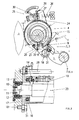
- Fig. 1 is an arch system with a feed table 1, one as a vibrating system 3rd trained sheet transport system 2, a drum 4 and a printing cylinder 5th shown.
- a vibrator 6 is mounted in a frame point 7 of the vibrating system 2 shown, in which gripper tongues 8 are spaced apart from one another over the machine width are that correspond to gripper cuffs 9.
- the drum 4 consists of a base body 10, which is connected in a rotationally fixed manner to a drum shaft 11 and which is received on both sides in machine walls 13 by means of roller bearings 12, and a drum shell 15.
- the base body 10 is coupled to the drum shell 15 via a coupling 14.
- the drum jacket 15 is mounted on bearing plates 17 with the aid of roller bearings 16.
- the bearing plates 17 are received in the machine walls 13 by means of bearing screws 31 so as to be pivotable about a pivot axis 18 such that an axis 19 of the drum shell 15 extends at a distance e from an axis of rotation 23 of the drum shaft 11.
- a gripper system 20, consisting of gripper fingers 21, which interact with gripper supports 22, is provided in the base body 10.
- the gripper pads 22 When rotated, the gripper pads 22 describe a circle with a radius R 1 , while the drum jacket 15 describes a circle with a radius R 2 .
- the radii R 1 and R 2 are the same or almost the same.
- the drum 4 is arranged in relation to the sheet transport system 2 designed as a vibrating system 3 and to the pressure cylinder 5 in such a way that a first gap A is formed between the drum shell 15 and the gripper cuffs 9 of the vibrating system 3 and a second gap B between the drum shell 15 and the pressure cylinder 5.
- the second gap B is adjustable in that the end shields 17 can be pivoted about the pivot axis 18 by means of an adjusting device 25.
- the end shields 17 are provided with a contact surface 24, which are held in operative connection with a positioning eccentric 27 by means of compression springs 26.
- the actuating eccentric 27 are arranged on an actuating shaft 28 which can be rotated with the aid of a lever 30 and fixed by means of a lock 29.
- the position of the pivot axis 18 is preferably selected such that it intersects a straight line g which is cut by the axis 19 of the drum shell 15 and runs through the frame point 7.
- the second gap B has an adjustment range of approximately 1.5 mm, it is also possible to implement this travel range without changing the first gap A if the pivot axis 18 extends within a line g extending on both sides of the straight line g Angle ⁇ is provided, the angle ⁇ extending over a range of approximately 0 ° to 30 °. For the sake of clarity, the position of the pivot axis 18 is shown in this area in FIG. 1.
- the sheets conveyed onto the feed table 1 are between the gripper tongues 8 and the gripper cuffs 9 of the vibration system 3 clamped and to the drum 4 transported and transferred to the gripper system 20 of the drum 4.
- the first gap A is dimensioned so that it is at least the height of the gripper tongues 8 and the maximum possible material thickness corresponds to the sheet being prepared.
- the one from the gripper system 20 captured sheets are transported to the printing cylinder 5 and to the ones not shown Hand over the gripper of the pressure cylinder 5.
- the second gap B to the material thickness of the processing Bow adjusted.
- the lock 29 is released and the actuating shaft 28 is rotated.
- the end shields 17 to Swivel axis 18 is given away and thus the drum jacket 15 approximates the pressure cylinder 5 or removed from it and thus a second gap corresponding to the material thickness B set.
Landscapes
- Feeding Of Articles By Means Other Than Belts Or Rollers (AREA)
Abstract
Description
Dieser im Radius kleiner gehaltene Trommelmantel bedingt aber einen großen Spalt zur Mantelfläche des nachgeordneten Druckzylinders, was bei dünnen Bedruckstoffen zu einem unruhigen sowie undefinierten Bogenlauf und damit zu einer nachteiligen Beeinflussung der Produktivität der Druckmaschine führt. Die unterschiedlichen Radien bewirken aber auch unterschiedliche Umfangsgeschwindigkeiten, die Ursache sind für das Ablegen von Farbe auf dem verkleinerten Trommelmantel beim Rückseitendruck.
Aus der DE 198 31 976 A1 ist es bekannt, den Schwinggreifer bei der Bewegung zurück zum Anlegtisch auf einer Bahn zu führen, die unter der Bogenführungsbahn liegt.
Nachteilig ist der hohe getriebetechnische Aufwand und die Möglichkeit der Einleitung von Schwingungen, wodurch die Produktivität der Druckmaschine nachteilig beeinflusst wird. Außerdem ist es auch bei derartigen Anordnungen üblich, zwischen dem Trommelmantel und der Mantelfläche des nachgeordneten Druckzylinders einen solchen Spalt vorzusehen, der es gestattet, sämtliche zur Verarbeitung vorgesehenen Materialstärken zu verarbeiten. Dieser nach der maximalen Materialstärke ausgelegte Spalt führt aber bei der Verarbeitung dünner Bedruckstoffe zu einer Produktivitätsminderung der Druckmaschine.
Weiterhin ist aus der DE 724 077 C eine Vorrichtung zum beschleunigten Wegziehen eines auf dem Anlegtisch ausgerichteten Bogens bekannt, bei der als Abdrängglied eine umlaufende Trommel dient, die exzentrisch zum Mittelpunkt der Greiferbahn gelagert ist und die mit der gleichen Drehgeschwindigkeit wie die Greifer umläuft. Der Gestellpunkt des Bogentransportsystem, der Gestellpunkt des Greifersystems und der Gestellpunkt des Druckzylinders liegen auf einer ersten Geraden.
Diese Vorrichtung ist lediglich zum beschleunigten Wegziehen eines Bogens geeignet, wobei sich beim Verändern der Exzentrizität der Trommel der Abstand zum Druckzylinder und zum Bogentransportsystem im gleichen Maß verändert wird. Außerdem eignet sich diese Vorrichtung nur für eine solche Maschinenkonfiguration, bei der die Gestellpunkte des Druckzylinders, des Greifersystems und des Bogentransportsystems auf einer Geraden liegen.
- Fig. 1
- eine Bogenanlage in der Seitenansicht,
- Fig. 2
- einen Längsschnitt einer teilweise dargestellten Trommel.
Im Grundkörper 10 ist ein Greifersystem 20, bestehend aus Greiferfingern 21, die mit Greiferauflagen 22 zusammenwirken, vorgesehen. Die Greiferauflagen 22 beschreiben bei Rotation einen Kreis mit einem Radius R1, während der Trommelmantel 15 einen Kreis mit einem Radius R2 beschreibt. Die Radien R1 und R2 sind gleich oder nahezu gleich. Die Trommel 4 ist so zu dem als Schwinganlage 3 ausgebildeten Bogentransportsystem 2 und zum Druckzylinder 5 angeordnet, dass sich zwischen dem Trommelmantel 15 und den Greiferaufschlägen 9 der Schwinganlage 3 ein erster Spalt A und zwischen Trommelmantel 15 und dem Druckzylinder 5 ein zweiter Spalt B bildet. Der zweite Spalt B ist einstellbar, indem die Lagerschilde 17 mittels einer Stelleinrichtung 25 um die Schwenkachse 18 geschwenkt werden können. Dazu sind die Lagerschilde 17 mit einer Anlauffläche 24 versehen, die mittels Druckfedern 26 in Wirkverbindung mit jeweils einem Stellexzenter 27 gehalten werden. Die Stellexzenter 27 sind auf einer Stellwelle 28 angeordnet, die mit Hilfe eines Hebels 30 verdreht und durch eine Arretierung 29 fixiert werden kann.
Um beim Einstellen des zweiten Spaltes B den ersten Spalt A konstant zu halten, wird die Lage der Schwenkachse 18 vorzugsweise so gewählt, dass diese eine Gerade g schneidet, welche von der Achse 19 des Trommelmantels 15 geschnitten wird und durch den Gestellpunkt 7 verläuft. Aufgrund der geringen Stellwege, der zweite Spalt B weist etwa einen Stellbereich von 1,5 mm auf, ist es auch möglich, diesen Stellweg zu realisieren, ohne den ersten Spalt A zu verändern, wenn die Schwenkachse 18 innerhalb eines sich beidseitig der Geraden g erstreckenden Winkels α vorgesehen wird, wobei der Winkel α sich über einen Bereich von etwa 0° bis 30° erstreckt. Aus Gründen der Übersichtlichkeit ist in Fig. 1 die Lage der Schwenkachse 18 in diesem Bereich dargestellt.
- 1
- Anlegtisch
- 2
- Bogentransportsystem
- 3
- Schwinganlage
- 4
- Trommel
- 5
- Druckzylinder
- 6
- Schwinger
- 7
- Gestellpunkt
- 8
- Greiferzungen
- 9
- Greiferaufschlag
- 10
- Grundkörper
- 11
- Trommelwelle
- 12
- Wälzlager
- 13
- Maschinenwand
- 14
- Koppel
- 15
- Trommelmantel
- 16
- Wälzlager
- 17
- Lagerschild
- 18
- Schwenkachse
- 19
- Achse
- 20
- Greifersystem
- 21
- Greiferfinger
- 22
- Greiferauflage
- 23
- Drehachse
- 24
- Anlauffläche
- 25
- Stelleinrichtung
- 26
- Druckfeder
- 27
- Stellexzenter
- 28
- Stellwelle
- 29
- Arretierung
- 30
- Hebel
- 31
- Lagerschraube
- A
- erster Spalt
- B
- zweiter Spalt
- R1
- Radius
- R2
- Radius
- g
- Gerade
- e
- Abstand
- α
- Winkel
Claims (6)
- Bogenanlage mit einem Bogentransportsystem, das Bogen von einem vorgeordneten Anlegtisch zu einem nachgeordneten, ein die Bogen erfassendes Greifersystem sowie einen die Bogen führenden Trommelmantel aufweisenden Trommel transportiert, die die Bogen einem Druckzylinder übergibt, wobei zwischen dem Trommelmantel und dem Bogentransportsystem ein erster Spalt sowie zwischen dem Trommelmantel und dem Druckzylinder ein zweiter Spalt vorgesehen ist, dadurch gekennzeichnet, dass der zweite Spalt (B) ohne oder nahezu ohne Veränderung des ersten Spaltes (A) einstellbar ausgeführt ist.
- Bogenanlage nach Anspruch 1, dadurch gekennzeichnet, dass der Trommelmantel (15) in Lagerschilden (17) aufgenommen ist, die um eine Schwenkachse (18) schwenkbar gelagert sind.
- Bogenanlage nach Anspruch 1 und 2, dadurch gekennzeichnet, dass die Lagerschilde (17) so angeordnet sind, dass eine Achse (19) des Trommelmantels (15) um einen Abstand (e) versetzt zur Drehachse (23) eines das Greifersystem (20) tragenden Grundkörpers (10) angeordnet ist.
- Bogenanlage nach Anspruch 1 bis 3, dadurch gekennzeichnet, dass die Schwenkachse (18) eine Gerade (g) schneidet, die die Achse (19) und einen Gestellpunkt (7) des Bogentransportsystems (2) verbindet.
- Bogenanlage nach Anspruch 1 bis 4, dadurch gekennzeichnet, dass die Schwenkachse (18) in einem Bereich angeordnet ist, der sich beidseitig der Geraden (g) innerhalb eines Winkels (α) erstreckt.
- Bogenanlage nach Anspruch 1 bis 5, dadurch gekennzeichnet, dass den Lagerschilden (17) eine diese um die Schwenkachse (18) schwenkende Stelleinrichtung (25) zugeordnet ist.
Applications Claiming Priority (2)
| Application Number | Priority Date | Filing Date | Title |
|---|---|---|---|
| DE2003109709 DE10309709A1 (de) | 2003-03-06 | 2003-03-06 | Bogenanlage |
| DE10309709 | 2003-03-06 |
Publications (2)
| Publication Number | Publication Date |
|---|---|
| EP1454744A1 true EP1454744A1 (de) | 2004-09-08 |
| EP1454744B1 EP1454744B1 (de) | 2011-05-11 |
Family
ID=32797835
Family Applications (1)
| Application Number | Title | Priority Date | Filing Date |
|---|---|---|---|
| EP20040002877 Expired - Lifetime EP1454744B1 (de) | 2003-03-06 | 2004-02-10 | Bogenanlage |
Country Status (2)
| Country | Link |
|---|---|
| EP (1) | EP1454744B1 (de) |
| DE (1) | DE10309709A1 (de) |
Citations (3)
| Publication number | Priority date | Publication date | Assignee | Title |
|---|---|---|---|---|
| DE724077C (de) | 1938-12-11 | 1942-08-17 | Planeta Druckmaschinenwerk Ag | Vorrichtung zum beschleunigten Wegziehen eines zu bedruckenden, bereits ausgerichteten Bogens |
| DE19831976A1 (de) | 1998-07-16 | 2000-01-20 | Heidelberger Druckmasch Ag | Vorrichtung zum Zuführen von Bogen zu einer Bogen verarbeitenden Maschine |
| US20020096070A1 (en) | 2001-01-22 | 2002-07-25 | Jens Friedrichs | Adjusting device for a sheet-fed rotary printing machine |
Family Cites Families (6)
| Publication number | Priority date | Publication date | Assignee | Title |
|---|---|---|---|---|
| DE1046069B (de) * | 1954-04-07 | 1958-12-11 | Roland Offsetmaschf | An- und Abstellvorrichtung fuer den Gummizylinder einer Offsetdruckmaschine |
| DE960994C (de) * | 1954-10-15 | 1957-03-28 | Roland Offsetmaschf | Bogen-Gummidruckmaschine fuer Schoen- und Widerdruck |
| US3690253A (en) * | 1971-06-10 | 1972-09-12 | Paul E Dreyer | Sheet feed press for printing small size sheets on both sides simultaneously |
| DE19841128A1 (de) * | 1998-09-09 | 2000-03-16 | Koenig & Bauer Ag | Bogenleiteinrichtung in der Bogenanlage |
| ATE246086T1 (de) * | 1999-02-26 | 2003-08-15 | Komori Printing Mach | Fördervorrichtung für bogenförmige gegenstände in einer bogenrotationsdruckmaschine |
| DE29904282U1 (de) * | 1999-03-10 | 1999-08-26 | Fischer, Andreas, 30982 Pattensen | Walzenanordnung |
-
2003
- 2003-03-06 DE DE2003109709 patent/DE10309709A1/de not_active Withdrawn
-
2004
- 2004-02-10 EP EP20040002877 patent/EP1454744B1/de not_active Expired - Lifetime
Patent Citations (3)
| Publication number | Priority date | Publication date | Assignee | Title |
|---|---|---|---|---|
| DE724077C (de) | 1938-12-11 | 1942-08-17 | Planeta Druckmaschinenwerk Ag | Vorrichtung zum beschleunigten Wegziehen eines zu bedruckenden, bereits ausgerichteten Bogens |
| DE19831976A1 (de) | 1998-07-16 | 2000-01-20 | Heidelberger Druckmasch Ag | Vorrichtung zum Zuführen von Bogen zu einer Bogen verarbeitenden Maschine |
| US20020096070A1 (en) | 2001-01-22 | 2002-07-25 | Jens Friedrichs | Adjusting device for a sheet-fed rotary printing machine |
Also Published As
| Publication number | Publication date |
|---|---|
| EP1454744B1 (de) | 2011-05-11 |
| DE10309709A1 (de) | 2004-09-16 |
Similar Documents
| Publication | Publication Date | Title |
|---|---|---|
| EP0005863B1 (de) | Pneumatische Seitenziehvorrichtung zum seitlichen Ausrichten eines Bogens auf dem Anlagetisch einer bogenverarbeitenden Maschine, insbesondere Druckmaschine | |
| DE3008231C2 (de) | ||
| DE10023940B4 (de) | Vorrichtung zum Ausrichten bogenförmigen Materials während des Transports | |
| EP3248918B1 (de) | Bogenübernahme in anlegeeinheit | |
| DE69403579T2 (de) | Papierfördervorrichtung für eine Bogendruckmaschine | |
| DE4239254C2 (de) | Einrichtung zum Einstellen der Anlegmarken | |
| WO2001038095A1 (de) | Farbwerk für eine druckmaschine | |
| DE4230218A1 (de) | Schwenkbarer Vorgreifer einer Bogendruckmaschine | |
| EP0036496B1 (de) | Vorrichtung zum seitlichen Ausrichten von selbsttätig zugeführten Bogen an Druckmaschinen | |
| DE2902047C2 (de) | Klein-Offset-Druckmaschine | |
| DE2452050C2 (de) | Vorrichtung zum passergerechten Anlegen von Bogen in Bogenrotationsdruckmaschinen | |
| DD282438A5 (de) | Vorrichtung zum zufuehren von bogen an eine bogenverarbeitende maschine, insbesondere druckmaschine | |
| EP1454744B1 (de) | Bogenanlage | |
| DE4142792C2 (de) | Vorrichtung zur Einstellung der Druckpressung von Zylindern in Druckmaschinen | |
| DE3736808A1 (de) | Einrichtung zum steuern der greifer eines vorgreifers in bogenverarbeitenden maschinen | |
| EP0250963B1 (de) | Vorrichtung zum Antrieb eines schwingenden Vorgreifers einer Druckmaschine | |
| DE4016304A1 (de) | Vorrichtung zum ausrichten schuppenfoermig unterlappt gefoerderter bogen | |
| EP0452721A2 (de) | Saugersteuerung in Bogenübergabetrommeln in Mehrfarben-Bogenrotationsdruckmaschinen | |
| DE10355515A1 (de) | Rotierender Vorgreifer | |
| DE10155115B4 (de) | Einrichtung zum Einstellen von Anlegmarken | |
| EP1356932B1 (de) | Antrieb eines Vorgreifers | |
| DE10309708A1 (de) | Bogenanlage | |
| EP1357070A2 (de) | Einrichtung zum Ausrichten von Bogen | |
| DE4108482C2 (de) | Einrichtung zum Steuern von Greifern eines Bogenbeschleunigungssystems | |
| DE4431679C2 (de) | Kurvengesteuerter Antrieb für eine Schwinganlage |
Legal Events
| Date | Code | Title | Description |
|---|---|---|---|
| PUAI | Public reference made under article 153(3) epc to a published international application that has entered the european phase |
Free format text: ORIGINAL CODE: 0009012 |
|
| 17P | Request for examination filed |
Effective date: 20040607 |
|
| AK | Designated contracting states |
Kind code of ref document: A1 Designated state(s): AT BE BG CH CY CZ DE DK EE ES FI FR GB GR HU IE IT LI LU MC NL PT RO SE SI SK TR |
|
| AX | Request for extension of the european patent |
Extension state: AL LT LV MK |
|
| AKX | Designation fees paid |
Designated state(s): DE FR GB |
|
| 17Q | First examination report despatched |
Effective date: 20090520 |
|
| GRAP | Despatch of communication of intention to grant a patent |
Free format text: ORIGINAL CODE: EPIDOSNIGR1 |
|
| GRAS | Grant fee paid |
Free format text: ORIGINAL CODE: EPIDOSNIGR3 |
|
| GRAA | (expected) grant |
Free format text: ORIGINAL CODE: 0009210 |
|
| AK | Designated contracting states |
Kind code of ref document: B1 Designated state(s): DE FR GB |
|
| REG | Reference to a national code |
Ref country code: GB Ref legal event code: FG4D Free format text: NOT ENGLISH |
|
| REG | Reference to a national code |
Ref country code: DE Ref legal event code: R096 Ref document number: 502004012483 Country of ref document: DE Effective date: 20110622 |
|
| PLBE | No opposition filed within time limit |
Free format text: ORIGINAL CODE: 0009261 |
|
| STAA | Information on the status of an ep patent application or granted ep patent |
Free format text: STATUS: NO OPPOSITION FILED WITHIN TIME LIMIT |
|
| 26N | No opposition filed |
Effective date: 20120214 |
|
| REG | Reference to a national code |
Ref country code: DE Ref legal event code: R097 Ref document number: 502004012483 Country of ref document: DE Effective date: 20120214 |
|
| PGFP | Annual fee paid to national office [announced via postgrant information from national office to epo] |
Ref country code: DE Payment date: 20130223 Year of fee payment: 10 Ref country code: FR Payment date: 20130301 Year of fee payment: 10 Ref country code: GB Payment date: 20130218 Year of fee payment: 10 |
|
| REG | Reference to a national code |
Ref country code: DE Ref legal event code: R119 Ref document number: 502004012483 Country of ref document: DE |
|
| GBPC | Gb: european patent ceased through non-payment of renewal fee |
Effective date: 20140210 |
|
| REG | Reference to a national code |
Ref country code: FR Ref legal event code: ST Effective date: 20141031 |
|
| REG | Reference to a national code |
Ref country code: DE Ref legal event code: R119 Ref document number: 502004012483 Country of ref document: DE Effective date: 20140902 |
|
| PG25 | Lapsed in a contracting state [announced via postgrant information from national office to epo] |
Ref country code: FR Free format text: LAPSE BECAUSE OF NON-PAYMENT OF DUE FEES Effective date: 20140228 Ref country code: GB Free format text: LAPSE BECAUSE OF NON-PAYMENT OF DUE FEES Effective date: 20140210 Ref country code: DE Free format text: LAPSE BECAUSE OF NON-PAYMENT OF DUE FEES Effective date: 20140902 |