EP1452370A2 - Stauraum für ein abnehmbares KFZ-Dach - Google Patents
Stauraum für ein abnehmbares KFZ-Dach Download PDFInfo
- Publication number
- EP1452370A2 EP1452370A2 EP03027596A EP03027596A EP1452370A2 EP 1452370 A2 EP1452370 A2 EP 1452370A2 EP 03027596 A EP03027596 A EP 03027596A EP 03027596 A EP03027596 A EP 03027596A EP 1452370 A2 EP1452370 A2 EP 1452370A2
- Authority
- EP
- European Patent Office
- Prior art keywords
- roof
- storage space
- removable
- roof element
- receptacles
- Prior art date
- Legal status (The legal status is an assumption and is not a legal conclusion. Google has not performed a legal analysis and makes no representation as to the accuracy of the status listed.)
- Granted
Links
Images


Classifications
-
- B—PERFORMING OPERATIONS; TRANSPORTING
- B60—VEHICLES IN GENERAL
- B60J—WINDOWS, WINDSCREENS, NON-FIXED ROOFS, DOORS, OR SIMILAR DEVICES FOR VEHICLES; REMOVABLE EXTERNAL PROTECTIVE COVERINGS SPECIALLY ADAPTED FOR VEHICLES
- B60J7/00—Non-fixed roofs; Roofs with movable panels, e.g. rotary sunroofs
- B60J7/20—Vehicle storage compartments for roof parts or for collapsible flexible tops
- B60J7/206—Vehicle storage compartments for roof parts or for collapsible flexible tops being arranged at the vehicle front
-
- B—PERFORMING OPERATIONS; TRANSPORTING
- B60—VEHICLES IN GENERAL
- B60J—WINDOWS, WINDSCREENS, NON-FIXED ROOFS, DOORS, OR SIMILAR DEVICES FOR VEHICLES; REMOVABLE EXTERNAL PROTECTIVE COVERINGS SPECIALLY ADAPTED FOR VEHICLES
- B60J7/00—Non-fixed roofs; Roofs with movable panels, e.g. rotary sunroofs
- B60J7/08—Non-fixed roofs; Roofs with movable panels, e.g. rotary sunroofs of non-sliding type, i.e. movable or removable roofs or panels, e.g. let-down tops or roofs capable of being easily detached or of assuming a collapsed or inoperative position
- B60J7/10—Non-fixed roofs; Roofs with movable panels, e.g. rotary sunroofs of non-sliding type, i.e. movable or removable roofs or panels, e.g. let-down tops or roofs capable of being easily detached or of assuming a collapsed or inoperative position readily detachable, e.g. tarpaulins with frames, or fastenings for tarpaulins
- B60J7/106—Non-fixed roofs; Roofs with movable panels, e.g. rotary sunroofs of non-sliding type, i.e. movable or removable roofs or panels, e.g. let-down tops or roofs capable of being easily detached or of assuming a collapsed or inoperative position readily detachable, e.g. tarpaulins with frames, or fastenings for tarpaulins readily detachable hard-tops
Definitions
- the invention relates to a removable roof for a motor vehicle according to the preamble of claim 1
- a removable from a motor vehicle roof is made of dimensionally stable Plastic forth that in a position of use a passenger compartment, for example. Between a windshield frame and a roll bar arched. In the from Motor vehicle detached position is said roof in a storage space accommodated, which is covered by a hood. To hold the roof in Storage space are receptacles that embrace the edges of the roof, with one of the Shooting includes an elastic section that extends into an adjacent edge move the roof releasing position.
- the object of the invention is to a removable roof of a motor vehicle so Make it easy in a bulky storage space of a construction of the motor vehicle can be used. But it should also be ensured that the Holder in the storage space for the roof is characterized by simplicity and good function distinguished.
- first Roof element and the second roof element of the roof by their superimposed Arrangement in a compact designed storage space can be accommodated conveniently can, by means of the recordings and the holding devices. It is advantageous that the first roof element as under roof element rotated approximately 180 ° to Construction position of the roof and the second roof element as upper roof element in Construction position is arranged in the storage space.
- the manual insertion process of the two Roof elements in the storage space is facilitated by the shots that the corners of the Limit roof elements with positive locking. These shots are made by molding sections having constituting inserts of the storage space, wherein at least a part of the receptacles is provided with mold sections for the lower and the upper roof element. After all the holding devices are shown as lashing, the ends under Interposition of gripping elements with vehicle-fixed support members interact.
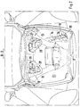
- a motor vehicle 1 of the sports car category - dynamic and stylish styling as well Demanding engine power - is provided by one between wheel axles, but adjacent to the Rear axle arranged drive unit - not shown - driven and includes a structure 2 with a windshield frame 3 and a roll bar 4. Between the windshield frame 3 and the roll bar 4, a removable extends Roof 5, which consists of dimensionally stable material, for example. Plastic and two in one Center longitudinal plane A-A of the motor vehicle 1 composite first and second Roof elements 6 and 7 includes. In a state solved by the structure 2 of the roof 5 it is possible, it or its roof elements 6 and 7 in a storage space. 8 insert, which extends between a bow 9 and a windshield 10.
- the storage space 8 is formed in the manner of a trunk and by means of a hood 11th covered, with a trough-shaped storage wall 12 opposite upright Side wall sections 13 and 14 has, which pass into a bottom 15.
- a trough-shaped storage wall 12 opposite upright Side wall sections 13 and 14 has, which pass into a bottom 15.
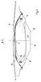
- designed storage space are the first roof element 6 and the second roof element. 7 superimposed - Figures 5 and 6 - arranged, stored in receptacles 16,17 and 18 and by means of holding devices 19 and 20 - Figures 2, 3 and 4 - fixed.
- first roof element 6 as the lower roof element and the second roof element 7 designed as an upper roof element, which first roof element 6 i. E. the lower one around 180 ° to the construction position of the roof 5 is rotated, whereas the second roof element 7, that is, the upper, approximately constructions takes position - Figures 5 and 6 -.
- the Construction position of the roof 5 is shown in FIG. 1 and corresponds to the state when it is placed between windshield frame 3 and roll bar 4.
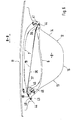
- the receptacles 16, 17 and 18 limit positive fit corners 21, 22 of the first Roof element 6 - Fig. 3 - or corners 23, 24 and 25 of the second roof element. 7 - Fig. 4 -.
- the receptacles 16, 17 and 18 with mold sections 26, 27th and 28, 29 and 30 provided in plastic inserts 31, 32 and 33 of the storage space 8 are provided.
- the shots 16 and 17 are the Mold sections 26, 27 and 28, 29 for the first and the second roof element 6, 7 integrated.
- the receptacle 18, comprising a slot-shaped mold section 34, is in the side wall portion 14 of the storage space 8 is arranged.
- the holding devices 19, 20 for the first roof element 6 and the second roof element 7 are formed by lashing elements 35, 36, which are located between the Sidewall sections 13,14 extend, said hot lashing elements run in Vehicle transverse direction B-B, and both the first lower roof element 6 as well as the second upper roof element 7 are with at least one lashing element, namely 35 and 36 respectively held.
- Each lashing element e.g. 35 is at its with a flexible lashing 37 - Fig. 6 - connected ends 38,39 provided with gripping elements 40,41, which has a U-shaped Cross-section and with tab-like support members 42, 43 cooperate.
- the support members 42,43 are part of fitting parts 44, which in the Side wall sections 13,14 of the storage space 8 are sunk integrated.
- a support insert 46 is provided, the one ensures targeted guidance of the lashing 37.
Landscapes
- Engineering & Computer Science (AREA)
- Mechanical Engineering (AREA)
- Body Structure For Vehicles (AREA)
- Fittings On The Vehicle Exterior For Carrying Loads, And Devices For Holding Or Mounting Articles (AREA)
- Vehicle Step Arrangements And Article Storage (AREA)
Abstract
Description
- Fig. 1
- eine Ansicht von oben auf ein Kraftfahrzeug,
- Fig. 2
- eine Schrägansicht von vorne oben auf einen Stauraum des Kraftfahrzeugs,
- Fig. 3
- eine Ansicht entsprechend Fig. 4 mit einem ersten Dachelement,
- Fig. 4
- eine weitere Ansicht entsprechend Fig. 4 mit einem ersten Dachelement und einem zweiten Dachelement,
- Fig. 5
- einen Schnitt nach der Linie V-V der Fig. 1,
- Fig. 6
- einen Schnitt nach der Linie VI-VI der Fig.1.
Claims (10)
- Abnehmbares Dach für ein Kraftfahrzeug, das sich in einem vom Aufbau des Kraftfahrzeugs gelösten Zustand in einen Stauraum des Aufbaus einsetzen lässt und mittels Aufnahmen und Haltevorrichtungen in Lage gehalten wird, dadurch gekennzeichnet, dass zwei in einer Mittellängsebene (A-A) des Aufbaus (2) trennbare Dachelemente (6 und 7) des Dachs (5) als erstes Dachelement (6) und als zweites Dachelement (7) übereinanderliegend in die Aufnahmen (16,17,18) des Stauraums (8) eingesetzt und mittels Haltevorrichtungen (19) festgelegt sind.
- Abnehmbares Dach nach Anspruch 1, dadurch gekennzeichnet, dass das erste Dachelement (6) als unteres Dachelement etwa um 180° gedreht zur Konstruktionslage und das zweite Dachelement (7) als oberes Dachelement in etwa in Konstruktionslage im Stauraum (8) angeordnet sind.
- Abnehmbares Dach nach den Ansprüchen 1 und 2, dadurch gekennzeichnet, dass die Aufnahmen (16,17,18) Ecken (21,23; 23,24,25) der Dachelemente (6 und 7) formschlüssig begrenzend ausgebildet sind.
- Abnehmbares Dach nach Anspruch 3, dadurch gekennzeichnet, dass die Aufnahmen (16,17,18) durch Formabschnitte (26,27; 28,29,30) aufweisende Einsätze (31,32,33) des Stauraums (8) dargestellt sind.
- Abnehmbares Dach nach einem oder mehreren der vorangehenden Ansprüche, dadurch gekennzeichnet, dass zumindest ein Teil der Aufnahmen (16,17) mit Formabschnitten (26,27, 28,29) für das erste untere Dachelement (6) und das zweite obere Dachelement (7) versehen ist.
- Abnehmbares Dach nach Anspruch 1, dadurch gekennzeichnet, dass die Haltevorrichtungen (19,20) als Zurrelemente (35,36) ausgebildet sind, deren Enden (38,39) unter Zwischenschaltung von Greifelementen (40,41) mit Stützgliedern (42, 43) zusammenwirken.
- Abnehmbares Dach nach Anspruch 6, dadurch gekennzeichnet, dass die Stützglieder (42,43) als Beschlagteile (44) weitgehend versenkt in den Stauraum (8) integriert sind.
- Abnehmbares Dach nach den Ansprüchen 1 und 6, dadurch gekennzeichnet, dass sowohl das erste untere Dachelement (6) wie auch das zweite obere Dachelement (7) jeweils mit wenigstens einem Zurrelement ( 35 und 37) in Lage gehalten wird.
- Abnehmbares Dach nach Anspruch 8, dadurch gekennzeichnet, dass die Zurrelemente (35 und 36) in Fahrzeugquerrichtung (B-B) verlaufen.
- Abnehmbares Dach nach Anspruch 9, dadurch gekennzeichnet, dass zwischen einem seitlichen Dachrand (45) des ersten unteren Dachelements (6) und dem zugehörigen Zurrelement (35) ein Stützeinsatz (46) vorgesehen ist.
Applications Claiming Priority (2)
| Application Number | Priority Date | Filing Date | Title |
|---|---|---|---|
| DE10308762A DE10308762A1 (de) | 2003-02-28 | 2003-02-28 | Abnehmbares Dach für ein Kraftfahrzeug |
| DE10308762 | 2003-02-28 |
Publications (3)
| Publication Number | Publication Date |
|---|---|
| EP1452370A2 true EP1452370A2 (de) | 2004-09-01 |
| EP1452370A3 EP1452370A3 (de) | 2007-01-03 |
| EP1452370B1 EP1452370B1 (de) | 2010-09-29 |
Family
ID=32748110
Family Applications (1)
| Application Number | Title | Priority Date | Filing Date |
|---|---|---|---|
| EP03027596A Expired - Lifetime EP1452370B1 (de) | 2003-02-28 | 2003-12-02 | Stauraum für ein abnehmbares KFZ-Dach |
Country Status (4)
| Country | Link |
|---|---|
| US (1) | US6926330B2 (de) |
| EP (1) | EP1452370B1 (de) |
| JP (1) | JP2004262439A (de) |
| DE (2) | DE10308762A1 (de) |
Families Citing this family (9)
| Publication number | Priority date | Publication date | Assignee | Title |
|---|---|---|---|---|
| US7032964B2 (en) * | 2004-09-30 | 2006-04-25 | Kirk Albert W | Storage apparatus for automobile removable roof panels |
| US20090096238A1 (en) * | 2007-10-12 | 2009-04-16 | Doug Misch | Storage apparatus for removable roof panels |
| DE102009052230A1 (de) | 2009-11-06 | 2011-06-01 | Magna Car Top Systems Gmbh | Vorrichtung zum Verschließen einer Dachöffnung |
| DE102012106968B4 (de) | 2012-07-31 | 2023-11-23 | Dr. Ing. H.C. F. Porsche Aktiengesellschaft | Abnehmbares Dach für ein Kraftfahrzeug sowie Kraftfahrzeug |
| DE102012110163A1 (de) | 2012-10-24 | 2014-04-24 | Dr. Ing. H.C. F. Porsche Aktiengesellschaft | Kraftfahrzeug mit einer Aufnahmevorrichtung für zumindest zwei plattenförmige Elemente |
| DE102013106480B4 (de) * | 2013-06-21 | 2025-03-27 | Dr. Ing. H.C. F. Porsche Aktiengesellschaft | Vorrichtung zur Aufnahme von Dachelementen |
| US9539938B1 (en) * | 2015-12-07 | 2017-01-10 | GM Global Technology Operations LLC | Removable vehicle roof panel with stowing assistance lamps |
| KR101927186B1 (ko) * | 2017-02-13 | 2018-12-10 | 현대자동차 주식회사 | 타르가 루프 수납구조 |
| US11377038B2 (en) * | 2020-09-15 | 2022-07-05 | Ford Global Technologies, Llc | Vehicle door storage system and door storage method |
Citations (3)
| Publication number | Priority date | Publication date | Assignee | Title |
|---|---|---|---|---|
| US2215363A (en) | 1939-10-16 | 1940-09-17 | Frederick C Ruppel | Retractable automobile top |
| US3635518A (en) | 1968-11-22 | 1972-01-18 | Porsche Kg | Mounting of a roof attachment in the front or rear space |
| DE9406435U1 (de) | 1993-06-03 | 1994-06-09 | Steyr-Daimler-Puch Ag, Wien | Abnehmbares Dach für Kraftfahrzeuge |
Family Cites Families (7)
| Publication number | Priority date | Publication date | Assignee | Title |
|---|---|---|---|---|
| DE1505551A1 (de) * | 1966-02-25 | 1970-01-29 | Bayerische Motoren Werke Ag | Personenkraftwagen |
| US4171078A (en) * | 1978-03-13 | 1979-10-16 | Morgan Kent D | Automobile trunk storage rack |
| US4467944A (en) * | 1983-07-25 | 1984-08-28 | Manko Gene F | Storage apparatus for automobile T top inserts |
| JPH0339293Y2 (de) * | 1985-07-12 | 1991-08-19 | ||
| JPH04358924A (ja) * | 1991-06-05 | 1992-12-11 | Suzuki Motor Corp | 自動車の着脱自在のルーフパネル |
| US5193874A (en) * | 1991-09-05 | 1993-03-16 | Ltc Roll & Engineering Company | T-top insert storage rack with locking mechanism |
| JP2981947B2 (ja) * | 1992-02-20 | 1999-11-22 | 本田技研工業株式会社 | オープンルーフ式自動車における収納ルーフの保持装置 |
-
2003
- 2003-02-28 DE DE10308762A patent/DE10308762A1/de not_active Ceased
- 2003-12-02 EP EP03027596A patent/EP1452370B1/de not_active Expired - Lifetime
- 2003-12-02 DE DE50313128T patent/DE50313128D1/de not_active Expired - Lifetime
-
2004
- 2004-02-24 JP JP2004048489A patent/JP2004262439A/ja not_active Withdrawn
- 2004-02-27 US US10/787,249 patent/US6926330B2/en not_active Expired - Lifetime
Patent Citations (3)
| Publication number | Priority date | Publication date | Assignee | Title |
|---|---|---|---|---|
| US2215363A (en) | 1939-10-16 | 1940-09-17 | Frederick C Ruppel | Retractable automobile top |
| US3635518A (en) | 1968-11-22 | 1972-01-18 | Porsche Kg | Mounting of a roof attachment in the front or rear space |
| DE9406435U1 (de) | 1993-06-03 | 1994-06-09 | Steyr-Daimler-Puch Ag, Wien | Abnehmbares Dach für Kraftfahrzeuge |
Also Published As
| Publication number | Publication date |
|---|---|
| DE50313128D1 (de) | 2010-11-11 |
| US20040232734A1 (en) | 2004-11-25 |
| US6926330B2 (en) | 2005-08-09 |
| EP1452370A3 (de) | 2007-01-03 |
| EP1452370B1 (de) | 2010-09-29 |
| JP2004262439A (ja) | 2004-09-24 |
| DE10308762A1 (de) | 2004-09-16 |
Similar Documents
| Publication | Publication Date | Title |
|---|---|---|
| DE3429880C2 (de) | ||
| DE2331777A1 (de) | Kraftfahrzeug mit schiebedach | |
| EP1452370A2 (de) | Stauraum für ein abnehmbares KFZ-Dach | |
| DE3127525A1 (de) | "kraftfahrzeug mit einem einen rollbuegel aufweisenden aufbau und einem faltverdeck" | |
| DE102008036910A1 (de) | Faltdachanordnung | |
| DE19737349A1 (de) | Hardtop-Fahrzeug | |
| DE102007037212A1 (de) | Kraftfahrzeug mit einem fahrzeugdachseitigen Gepäckträger im Fahrzeuginnenraum | |
| DE102008036906A1 (de) | Faltdachanordnung | |
| DE3147214A1 (de) | "faltverdeck fuer fahrzeuge, insbesondere personenkraftwagen" | |
| DE10253881A1 (de) | Vorrichtung zum Abdecken einer Aussparung in einer Außenhülle eines Kraftfahrzeuges | |
| EP1744921A1 (de) | Verdeck eines cabriolet-kraftfahrzeuges | |
| DE10147016C2 (de) | Verstellbares Fahrzeugdach | |
| DE102008036909A1 (de) | Personenkraftwagen mit einem verstellbaren Dach | |
| DE102004018606A1 (de) | Dachstruktur für ein zu öffnendes starres Kraftfahrzeugdach | |
| DE19943808B4 (de) | Fahrzeug-Cabriodach mit Falthilfe für die in dessen Heckteil enthaltene Heckfensterscheibe | |
| DE102008036903A1 (de) | Faltdachanordnung | |
| DE102008039096A1 (de) | Faltverdeck für einen Personenkraftwagen | |
| DE102019212303A1 (de) | Fahrzeug mit abnehmbaren Dachelementen | |
| DE3102164A1 (de) | Kraftfahrzeug mit einem festen dach, das wenigstens eine oeffnung und eine flexible abdeckung fuer diese oeffnung aufweist | |
| EP2596972B1 (de) | Windschutzeinrichtung | |
| DE10252133A1 (de) | Ausklappbarer Lastenträger zur heckseitigen Anordnung an einem Kraftfahrzeug, insbesondere zum Transport von Fahrrädern | |
| DE102008051707A1 (de) | Dach mit einem Faltverdeck für einen Personenkraftwagen | |
| DE102007053530B3 (de) | Öffenbares Fahrzeugdach | |
| DE3433296C1 (de) | Kraftwagen | |
| DE10149471C1 (de) | Verstellbares Softtop-Fahrzeugverdeck |
Legal Events
| Date | Code | Title | Description |
|---|---|---|---|
| PUAI | Public reference made under article 153(3) epc to a published international application that has entered the european phase |
Free format text: ORIGINAL CODE: 0009012 |
|
| AK | Designated contracting states |
Kind code of ref document: A2 Designated state(s): AT BE BG CH CY CZ DE DK EE ES FI FR GB GR HU IE IT LI LU MC NL PT RO SE SI SK TR |
|
| AX | Request for extension of the european patent |
Extension state: AL LT LV MK |
|
| PUAL | Search report despatched |
Free format text: ORIGINAL CODE: 0009013 |
|
| AK | Designated contracting states |
Kind code of ref document: A3 Designated state(s): AT BE BG CH CY CZ DE DK EE ES FI FR GB GR HU IE IT LI LU MC NL PT RO SE SI SK TR |
|
| AX | Request for extension of the european patent |
Extension state: AL LT LV MK |
|
| 17P | Request for examination filed |
Effective date: 20070703 |
|
| AKX | Designation fees paid |
Designated state(s): DE FR GB IT |
|
| 17Q | First examination report despatched |
Effective date: 20071213 |
|
| RAP1 | Party data changed (applicant data changed or rights of an application transferred) |
Owner name: DR. ING. H.C. F. PORSCHE AKTIENGESELLSCHAFT |
|
| RAP1 | Party data changed (applicant data changed or rights of an application transferred) |
Owner name: DR. ING. H.C. F. PORSCHE AKTIENGESELLSCHAFT |
|
| RAP1 | Party data changed (applicant data changed or rights of an application transferred) |
Owner name: DR. ING. H.C. F. PORSCHE AG |
|
| GRAC | Information related to communication of intention to grant a patent modified |
Free format text: ORIGINAL CODE: EPIDOSCIGR1 |
|
| GRAP | Despatch of communication of intention to grant a patent |
Free format text: ORIGINAL CODE: EPIDOSNIGR1 |
|
| GRAS | Grant fee paid |
Free format text: ORIGINAL CODE: EPIDOSNIGR3 |
|
| GRAA | (expected) grant |
Free format text: ORIGINAL CODE: 0009210 |
|
| AK | Designated contracting states |
Kind code of ref document: B1 Designated state(s): DE FR GB IT |
|
| REG | Reference to a national code |
Ref country code: GB Ref legal event code: FG4D Free format text: NOT ENGLISH |
|
| REF | Corresponds to: |
Ref document number: 50313128 Country of ref document: DE Date of ref document: 20101111 Kind code of ref document: P |
|
| PLBE | No opposition filed within time limit |
Free format text: ORIGINAL CODE: 0009261 |
|
| STAA | Information on the status of an ep patent application or granted ep patent |
Free format text: STATUS: NO OPPOSITION FILED WITHIN TIME LIMIT |
|
| 26N | No opposition filed |
Effective date: 20110630 |
|
| REG | Reference to a national code |
Ref country code: DE Ref legal event code: R097 Ref document number: 50313128 Country of ref document: DE Effective date: 20110630 |
|
| REG | Reference to a national code |
Ref country code: FR Ref legal event code: PLFP Year of fee payment: 13 |
|
| REG | Reference to a national code |
Ref country code: FR Ref legal event code: PLFP Year of fee payment: 14 |
|
| REG | Reference to a national code |
Ref country code: FR Ref legal event code: PLFP Year of fee payment: 15 |
|
| PGFP | Annual fee paid to national office [announced via postgrant information from national office to epo] |
Ref country code: FR Payment date: 20171221 Year of fee payment: 15 Ref country code: DE Payment date: 20171204 Year of fee payment: 15 |
|
| PGFP | Annual fee paid to national office [announced via postgrant information from national office to epo] |
Ref country code: GB Payment date: 20171221 Year of fee payment: 15 |
|
| PGFP | Annual fee paid to national office [announced via postgrant information from national office to epo] |
Ref country code: IT Payment date: 20171221 Year of fee payment: 15 |
|
| REG | Reference to a national code |
Ref country code: DE Ref legal event code: R119 Ref document number: 50313128 Country of ref document: DE |
|
| GBPC | Gb: european patent ceased through non-payment of renewal fee |
Effective date: 20181202 |
|
| PG25 | Lapsed in a contracting state [announced via postgrant information from national office to epo] |
Ref country code: DE Free format text: LAPSE BECAUSE OF NON-PAYMENT OF DUE FEES Effective date: 20190702 Ref country code: IT Free format text: LAPSE BECAUSE OF NON-PAYMENT OF DUE FEES Effective date: 20181202 Ref country code: FR Free format text: LAPSE BECAUSE OF NON-PAYMENT OF DUE FEES Effective date: 20181231 |
|
| PG25 | Lapsed in a contracting state [announced via postgrant information from national office to epo] |
Ref country code: GB Free format text: LAPSE BECAUSE OF NON-PAYMENT OF DUE FEES Effective date: 20181202 |