EP1445359A2 - Kanalplattenadapter für eine Offenend-Rotorspinnvorrichtung - Google Patents
Kanalplattenadapter für eine Offenend-Rotorspinnvorrichtung Download PDFInfo
- Publication number
- EP1445359A2 EP1445359A2 EP04000300A EP04000300A EP1445359A2 EP 1445359 A2 EP1445359 A2 EP 1445359A2 EP 04000300 A EP04000300 A EP 04000300A EP 04000300 A EP04000300 A EP 04000300A EP 1445359 A2 EP1445359 A2 EP 1445359A2
- Authority
- EP
- European Patent Office
- Prior art keywords
- plate adapter
- nozzle
- thread take
- clip
- channel plate
- Prior art date
- Legal status (The legal status is an assumption and is not a legal conclusion. Google has not performed a legal analysis and makes no representation as to the accuracy of the status listed.)
- Granted
Links
Images


Classifications
-
- D—TEXTILES; PAPER
- D01—NATURAL OR MAN-MADE THREADS OR FIBRES; SPINNING
- D01H—SPINNING OR TWISTING
- D01H4/00—Open-end spinning machines or arrangements for imparting twist to independently moving fibres separated from slivers; Piecing arrangements therefor; Covering endless core threads with fibres by open-end spinning techniques
- D01H4/40—Removing running yarn from the yarn forming region, e.g. using tubes
-
- D—TEXTILES; PAPER
- D01—NATURAL OR MAN-MADE THREADS OR FIBRES; SPINNING
- D01H—SPINNING OR TWISTING
- D01H4/00—Open-end spinning machines or arrangements for imparting twist to independently moving fibres separated from slivers; Piecing arrangements therefor; Covering endless core threads with fibres by open-end spinning techniques
- D01H4/38—Channels for feeding fibres to the yarn forming region
Definitions
- the invention relates to a channel plate adapter for a Open-end rotor spinning device according to the preamble of Claim 1.
- Open-end rotor spinning devices in the area of their Fiber duct plate with a replaceable duct plate adapter are known and for example in the DE 43 34 485 A1 described in detail.
- a spinning rotor rotates at high speed in a rotor housing under vacuum during the spinning operation.
- the rotor housing is closed by a pivotably arranged cover, in which the fiber sliver opening device of the spinning device is also integrated.
- This fiber channel plate is either an integral part of the lid or is releasably attached to the lid.
- a channel plate adapter is interchangeably arranged in a central receptacle of the fiber channel plate and has a part of a fiber guide channel and a thread take-off nozzle in a central through bore.
- the duct plate adapters are in each case a specific spinning rotor shape or size.
- the duct plate adapter is therefore often included replaced.
- channel plate adapters as described in DE 197 29 192 A1, can be replaced without tools.
- These known duct plate adapters have a central extension with lateral fixing elements, when viewed in the installation direction. By acting on these fixing elements, which are arranged approximately in the region of the central axis of the channel plate adapter, by means of appropriate locking means, the channel plate adapter is fixed uniformly in the receptacle of the fiber channel plate. This means that false air is prevented from entering the rotor housing.
- Such channel plate adapters have a central one Through hole in which, usually replaceable, a thread take-off nozzle is arranged.
- Thread take-off nozzles are of various designs.
- DE 39 40 046 A1 describes, for example, a thread draw-off nozzle which has a mouth funnel made of ceramic, which is fixed in a steel mouth support, preferably by gluing.
- the mouth support in turn has an external thread that can be screwed into a corresponding internal thread in the area of the central through bore of the channel plate adapter.
- Thread take-off nozzle by means of special, additional Interchangeable clip closures on a fiber channel plate set.
- the clip closures are either on the Fiber channel plate attached and snap into appropriate approaches on the thread take-off nozzle or the clip fasteners Part of the thread take-off nozzle and then correspond with corresponding devices on the fiber channel plate.
- the device known from DE 37 29 425 A1 is, for example, somewhat complex due to its various individual parts. That is, the manufacturing cost of such channel plate adapters is relatively high.
- an open-end spinning device is known from DE 196 03 730 A1, in which the channel plate adapter, which is interchangeably arranged in a receptacle of the fiber channel plate, is inexpensively made of a plastic.
- a fiber guide channel made of an abrasion-resistant material is also cast in the channel plate adapter.
- Channel plate adapter has the particular advantage that a such channel plate adapter incomparably cheaper manufacture than all known channel plate adapters.
- the clip closure according to the invention the in one piece on the plastic body of the duct plate adapter is formed, not only ensures a reliable Fixation of the thread take-off nozzle, but also ensures that the thread take-off nozzle can be easily replaced at any time if necessary can be.
- a wear protection tube that can also be replaced in the through hole of the channel plate adapter is arranged.
- the wear protection tube is on the one hand on one rear stop within the through hole and will on the other hand through the clipped thread take-off nozzle locked.
- the wear protection tube is made of a highly wear-resistant material.
- This highly wear-resistant material prevents the resulting thread that runs through the thread take-off nozzle from being able to work into the plastic body of the channel plate adapter.
- Suitable highly wear-resistant materials are, for example, ceramic materials, alloyed steels, etc.
- the thread take-off nozzle also preferably consists of such a highly wear-resistant material. This means that the thread take-off nozzle is usually made from a technical ceramic material.
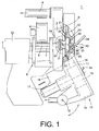
- FIG. 1 shows a side view of an open-end rotor spinning device 1 with a rotor housing 2 under vacuum, in which a spinning rotor 3 rotates at high speed.
- the spinning rotor 3 is supported in a known manner via its rotor shaft 7 on a support disk bearing 4; while the axial positioning of the spinning rotor 3 takes place via an axial bearing 33.
- the spinning rotor 3 is driven by means of a machine-long tangential belt 5, which a pressure roller 6 presses against the rotor shaft 7.
- the rotor housing 2 is connected via a vacuum line 8 to a vacuum source (not shown).
- the rotor housing 2 is closed on its front side 9 by a so-called fiber channel plate 10, which is part of a cover designed as a swivel housing 11.
- the fiber channel plate 10 is either a component of the swivel housing 11 or the fiber channel plate 10 is detachably attached to the swivel housing 11.
- further units of the open-end rotor spinning device 1, for example a sliver opening device 13 are installed in the swivel housing 11, which is swivel-mounted on a swivel axis 12.
- a sliver of feed sliver is drawn into the opening device 13 via a sliver feed cylinder 14, which is not shown here, and is broken down into individual fibers there by a sliver winding roller 15.
- the individual fibers are then conveyed to the spinning rotor 3 via a fiber guide channel 16.
- the sliver opening roller 15 is preferably driven by a tangential belt 17, while the sliver feed cylinder 14 is driven by a machine-long drive shaft or an electromotive individual drive 18.
- a pneumatically actuated dirt chamber 19 can furthermore be arranged below the fiber ribbon dissolving roller 15 for the dirt accumulating when the fiber ribbon is dissolved.
- the dirt chamber 19 is connected to a central dirt disposal device of the open-end rotor spinning machine via a corresponding suction line.
- the fiber duct plate 10 inserted into the swivel housing 11 has an annular recess 20 for positioning a lip sealing element 21 and a receptacle 22 open in the direction of the rotor housing 2 for an exchangeable duct plate adapter 24.
- the lateral contact surface 23 of the receptacle 22 is preferably frustoconical.
- the channel plate adapter 24 is made of a plastic and, as can be seen in particular from FIGS. 2 and 3, has the mouth region 34 of the fiber guide channel 16 and a central through-bore 26 for a thread take-off nozzle 27 opposite the spinning rotor 3.
- the fiber guide channel 16 is formed by a wear-resistant insert 42, which is firmly cast in during the manufacture of the channel plate adapter 24 made of plastic.
- a wear protection tube 36 is arranged in the central through bore 26 next to the thread take-off nozzle 27, to which a thread take-off tube 28 is connected.
- the thread take-off tube 28 thereby passes through a bore in the extension 29 of an insert body 25 which has at least one fixing projection 31 at the end.
- the fixing projection 31 extends essentially orthogonally to the longitudinal axis 30 of the extension 29 and is engaged behind by a locking means 32.
- This type of attachment of a duct plate adapter is known and is described in detail, for example, in DE 197 29 192 A1.
- the duct plate adapter 24 has, in the region of its central through bore 26, a clip closure 37 which is integrally formed on the plastic body of the duct plate adapter 24.
- This clip fastener 37 for locking the yarn withdrawal nozzle 27 has centering members 38 and via clip elements 39.
- the centering elements 38 are designed as circle segments 38A, 38B, 38C, etc., the common inner diameter D is set inside so that it only slightly maximum above the Diameter D max of the edge contour 40 of the thread take-off nozzle 27.
- the clip elements 39 which are each arranged between the centering members 38, each have a conical contact surface 41 on their inside facing the thread take-off nozzle 37, which corresponds to a correspondingly conical contact surface on the outside of the edge contour 40 of the thread take-off nozzle 27. That is, the clip elements 39 partially cover the outside of the edge contour 40 of the thread take-off nozzle 27.
Landscapes
- Engineering & Computer Science (AREA)
- Mechanical Engineering (AREA)
- Textile Engineering (AREA)
- Spinning Or Twisting Of Yarns (AREA)
Abstract
Description
Das Rotorgehäuse ist dabei durch einen schwenkbar angeordneten Deckel verschlossen, in den außerdem die Faserbandauflöseeinrichtung der Spinnvorrichtung integriert ist.
Das heißt, an der Frontseite des Rotorgehäuses liegt eine Lippendichtung an, die in einer Ringnut einer sogenannten Faserkanalplatte angeordnet ist.
Diese Faserkanalplatte ist dabei entweder ein integraler Bestandteil des Deckels oder ist lösbar am Deckel festgelegt. In einer zentrischen Aufnahme der Faserkanalplatte ist außerdem auswechselbar ein Kanalplattenadapter angeordnet, der einen Teil eines Faserleitkanals sowie in einer zentrischen Durchgangsbohrung eine Fadenabzugsdüse aufweist.
In der DE 43 34 485 A1 ist beispielsweise ein Kanalplattenadapter beschrieben, der mittels die Rückwand der Aufnahme durchfassender Schrauben luftdicht in der Aufnahme der Faserkanalplatte festgelegt werden kann.
Eine solche Befestigungsart erfordert allerdings den Einsatz eines Werkzeuges.
Diese bekannten Kanalplattenadapter weisen, in Einbaurichtung gesehen, einen zentralen Fortsatz mit seitlichen Fixierelementen auf.
Durch Beaufschlagung dieser etwa im Bereich der Mittelachse des Kanalplattenadapters angeordneten Fixierelemente durch entsprechende Arretierungsmittel wird der Kanalplattenadapter gleichmäßig in der Aufnahme der Faserkanalplatte fixiert.
Das heißt, es wird verhindert, daß Falschluft in das Rotorgehäuse eintreten kann.
Der Mündungsträger weist seinerseits ein Außengewinde auf, das in ein entsprechendes Innengewinde im Bereich der zentralen Durchgangsbohrung des Kanalplattenadapters einschraubbar ist.
Diese ferromagnetische Anlagefläche korrespondiert mit Permanentmagneten, die fest in den Kanalplattenadapter eingelassen sind.
Das heißt, die Herstellungskosten derartig ausgebildeter Kanalplattenadapter sind relativ hoch.
In den Kanalplattenadapter ist dabei ein aus einem abriebfesten Material gefertigter Faserleitkanal mit eiengegossen.
Das heißt, die kreissegmentförmig ausgebildeten Zentrierglieder des Klippverschlusses liegen mit ihrem Innendurchmesser unmittelbar am maximalen Außendurchmesser der Fadenabzugsdüse an und zentrieren die Fadenabzugsdüse dadurch exakt.
Da gleichzeitig die Klippelemente des Klippverschlusses die Randkontur der Fadenabzugsdüse, zumindest teilweise, überfassen, ist die Fadenabzugsdüse außerdem sofort sicher gehalten.
Dieses hochverschleißfeste Material verhindert, daß sich der entstehende und durch die Fadenabzugsdüse ablaufende Faden in den Kunststoffkörper des Kanalplattenadapters einarbeiten kann.
Geeignete hochverschleißfeste Werkstoffe sind beispielsweise Keramikwerkstoffe, legierte Stähle, etc.
Das heißt, in der Regel ist die Fadenabzugsdüse aus einem technischen Keramikwerkstoff gefertigt.
- Fig. 1
- eine Offenend-Rotorspinnvorrichtung mit einem in einem Rotorgehäuse umlaufenden Spinnrotor, wobei das Rotorgehäuse durch einen Deckel, in den eine Faserkanalplatte integriert ist, verschlossen ist, und die Faserkanalplatte eine Aufnahme zur Positionierung eines erfindungsgemäßen, auswechselbaren, Kanalplattenadapters aufweist,
- Fig. 2
- den erfindungsgemäßen Kanalplattenadapter in Seitenansicht, teilweise im Schnitt,
- Fig. 3
- eine perspektivische Ansicht des erfindungsgemäßen Kanalplattenadapters mit einer in einer zentralen Durchgangsbohrung festlegbaren Fadenabzugsdüse sowie einem nachgeschalteten Verschleißschutzröhrchen.
Der Antrieb des Spinnrotors 3 erfolgt, wie bekannt, mittels eines maschinenlangen Tangentialriemens 5, den eine Andrückrolle 6 gegen den Rotorschaft 7 drückt.
Zur Erzeugung des notwendigen Spinnunterdruckes ist das Rotorgehäuse 2 über eine Unterdruckleitung 8 an eine (nicht dargestellte) Unterdruckquelle angeschlossen.
Die Faserkanalplatte 10 ist dabei entweder ein Bestandteil des Schwenkgehäuses 11 oder die Faserkanalplatte 10 ist lösbar am Schwenkgehäuse 11 befestigt.
Wie in Figur 1 weiter angedeutet, sind in das Schwenkgehäuse 11, das eine Schwenkachse 12 schwenkbar gelagert ist, weitere Aggregate der Offenend-Rotorspinnvorrichtung 1, beispielsweise eine Faserbandauflöseeinrichtung 13, eingebaut.
Das heißt, über einen, hier nicht näher dargestellten, Faserbandeinzugszylinder 14 wird ein Vorlagefaserband in die Auflöseeinrichtung 13 eingezogen und dort durch eine Faserbandauflösewalze 15 in Einzelfasern zerlegt.
Die Einzelfasern werden anschließend über einen Faserleitkanal 16 zum Spinnrotor 3 befördert.
Die Faserbandauflösewalze 15 wird dabei vorzugsweise durch einen Tangentialriemen 17 angetrieben, während der Antrieb des Faserbandeinzugszylinders 14 über eine maschinenlange Antriebswelle oder einen elektromotorischen Einzelantrieb 18 erfolgt.
Im Schwenkgehäuse 11 kann des weiteren, unterhalb der Faserbandauflösewalze 15, eine pneumatisch beaufschlagbare Schmutzkammer 19 für den bei der Auflösung des Faserbandes anfallenden Schmutz angeordnet sein.
Die Schmutzkammer 19 ist in diesem Fall über eine entsprechende Absaugleitung an eine zentrale Schmutzentsorgungseinrichtung der Offenend-Rotorspinnmaschine angeschlossen.
Die seitliche Anlagefläche 23 der Aufnahme 22 ist vorzugsweise kegelstumpfförmig ausgebildet. Durch eine solche Ausbildung kann sichergestellt werden, das der winkelgenau ausgerichtete Kanalplattenadapter 24 mit seinem Einsatzkörper 25 luftdicht in der Aufnahme 22 der Faserkanalplatte 10 positioniert ist. Das heißt, durch eine solche Ausbildung wird vermieden, daß beim Einsetzen des Kanalplattenadapters 24 Undichtigkeiten aufgrund von Passungsfehlern auftreten können.
Im Betriebszustand ist in der zentralen Durchgangsbohrung 26 neben der Fadenabzugsdüse 27 noch ein Verschleißschutzröhrchen 36 angeordnet, an das sich ein Fadenabzugsröhrchen 28 anschließt.
Das Fadenabzugsröhrchen 28 durchfaßt dabei eine Bohrung im Fortsatz 29 eines Einsatzkörpers 25, der endseitig wenigstens einen Fixieransatz 31 aufweist.
Der Fixieransatz 31 erstreckt sich im wesentlichen orthogonal zur Längsachse 30 des Fortsatzes 29 und wird von einem Arretierungsmittel 32 hintergriffen.
Diese Art der Befestigung eines Kanalplattenadapters ist bekannt und beispielsweise in der DE 197 29 192 A1 ausführlich beschrieben.
Dieser Klippverschluß 37 zum Arretieren der Fadenabzugsdüse 27 verfügt über Zentrierglieder 38 und über Klippelemente 39. Die Zentrierglieder 38 sind dabei als Kreissegmente 38A, 38B, 38C, etc. ausgebildet, deren gemeinsamer Innendurchmesser Dinnen so gewählt ist, daß er nur geringfügig über dem maximalen Durchmesser Dmax der Randkontur 40 der Fadenabzugsdüse 27 liegt.
Die Klippelemente 39, die jeweils zwischen den Zentriergliedern 38 angeordnet sind, weisen auf ihrer der Fadenabzugsdüse 37 zugewandten Innenseite jeweils eine konische Anlagefläche 41 auf, die mit einer entsprechend konisch ausgebildeten Anlagefläche auf der Außenseite der Randkontur 40 der Fadenabzugsdüse 27 korrespondiert.
Das heißt, die Klippelemente 39 überfassen teilweise die Außenseite der Randkontur 40 der Fadenabzugsdüse 27.
Claims (8)
- Kanalplattenadapter für eine Offenend-Rotorspinnvorrichtung, die einen innerhalb eines unterdruckbeaufschlagbaren Rotorgehäuses mit hoher Drehzahl umlaufenden Spinnrotor besitzt, wobei der aus einem Kunststoff gefertigte Kanalplattenadapter, der den Mündungsbereich eines Faserleitkanals sowie eine zentrische Durchgangsbohrung für eine Fadenabzugsdüse aufweist, auswechselbar in einer Aufnahme einer Faserkanalplatte angeordnet ist, die das Rotorgehäuse während des Spinnbetriebes verschließt,
dadurch gekennzeichnet, daß der Kanalplattenadapter (24) im Eingangsbereich der Durchgangsbohrung (26) einen einstückig angeformten Klippverschluß (37) zum Zentrieren und Fixieren der Fadenabzugsdüse (27) aufweist. - Kanalplattenadapter nach Anspruch 1, dadurch gekennzeichnet, daß der Klippverschluß (37) aus starren, auf die Randkontur (40) der Fadenabzugsdüse (27) abgestimmten Zentriergliedern (38) und elastischen Klippelementen (39) besteht.
- Kanalplattenadapter nach Anspruch 2, dadurch gekennzeichnet, daß der Klippverschluß (37) wenigstens zwei beabstandet angeordnete Zentrierglieder (38A, 38B) aufweist, zwischen denen jeweils wenigstens ein Klippelement (39), das die Randkontur (40) der Fadenabzugsdüse (27) wenigstens teilweise überfaßt, positioniert ist.
- Kanalplattenadapter nach Anspruch 3, dadurch gekennzeichnet, daß die Zentrierglieder (38A, 38B, etc.) kreissegmentförmig ausgebildet und so angeordnet sind, daß die Fadenabzugsdüse (27) mit ihrem maximalen Außendurchmesser (Dmax) am gemeinsamen Innendurchmesser (Dinnen) der Zentrierglieder (38A, 38B, etc.) anliegt.
- Kanalplattenadapter nach Anspruch 3, dadurch gekennzeichnet, daß die Klippelemente (39) jeweils eine konisch verlaufende, innere Anlagefläche (41) aufweisen, die mit einer entsprechend konisch ausgebildeten Außenfläche der Randkontur (40) der Fadenabzugsdüse (27) korrespondiert.
- Kanalplattenadapter nach Anspruch 3, dadurch gekennzeichnet, daß in der Durchgangsbohrung (26) des Kanalplattenadapters (24), an einem Anschlag (34) abgestützt, ein Verschleißschutzröhrchen (36) angeordnet ist, das durch die in ihrer Betriebsstellung positionierte, durch den Klippverschluß (37) fixierte Fadenabzugsdüse (27) festgelegt ist.
- Kanalplattenadapter nach Anspruch 6, dadurch gekennzeichnet, daß das Verschleißschutzröhrchen (36) aus einem verschleißfesten Material, zum Beispiel Stahl, technischer Keramik, etc. gefertigt ist.
- Kanalplattenadapter nach Anspruch 6, dadurch gekennzeichnet, daß die Fadenabzugsdüse (27) aus einem technischen Keramikwerkstoff gefertigt ist.
Applications Claiming Priority (2)
| Application Number | Priority Date | Filing Date | Title |
|---|---|---|---|
| DE10305279A DE10305279A1 (de) | 2003-02-08 | 2003-02-08 | Kanalplattenadapter für eine Offenend-Rotorspinnvorrichtung |
| DE10305279 | 2003-02-08 |
Publications (3)
| Publication Number | Publication Date |
|---|---|
| EP1445359A2 true EP1445359A2 (de) | 2004-08-11 |
| EP1445359A3 EP1445359A3 (de) | 2005-04-13 |
| EP1445359B1 EP1445359B1 (de) | 2010-10-13 |
Family
ID=32603217
Family Applications (1)
| Application Number | Title | Priority Date | Filing Date |
|---|---|---|---|
| EP04000300A Expired - Lifetime EP1445359B1 (de) | 2003-02-08 | 2004-01-09 | Kanalplattenadapter für eine Offenend-Rotorspinnvorrichtung |
Country Status (4)
| Country | Link |
|---|---|
| US (1) | US7036301B2 (de) |
| EP (1) | EP1445359B1 (de) |
| CN (1) | CN100526526C (de) |
| DE (2) | DE10305279A1 (de) |
Cited By (2)
| Publication number | Priority date | Publication date | Assignee | Title |
|---|---|---|---|---|
| EP1795633A3 (de) * | 2005-12-06 | 2009-11-04 | Rieter Ingolstadt GmbH | Offenend-Spinnvorrichtung mit austauschbarem Drallstauelement |
| TWI397622B (zh) * | 2006-01-10 | 2013-06-01 | Rieter Ingolstadt Spinnerei | Rotor Spinning Device with Rotor Spinning |
Families Citing this family (11)
| Publication number | Priority date | Publication date | Assignee | Title |
|---|---|---|---|---|
| DE102004029020A1 (de) * | 2004-06-16 | 2005-12-29 | Saurer Gmbh & Co. Kg | Verfahren und Vorrichtung zum Betreiben einer Offenend-Rotorspinnvorrichtung |
| DE102011010925A1 (de) * | 2011-02-11 | 2012-08-16 | Oerlikon Textile Gmbh & Co. Kg | Faserleitkanaleinrichtung für eine Offenend-Spinnvorrichtung |
| US8643244B2 (en) | 2011-07-25 | 2014-02-04 | Hamilton Sundstrand Corporation | Strength cast rotor for an induction motor |
| DE102011120106A1 (de) | 2011-12-02 | 2013-06-06 | Oerlikon Textile Gmbh & Co. Kg | Deckelelement einer Offenend-Spinnvorrichtung zum Verschließen eines besaugten, nach vorne hin offenen Rotorgehäuses |
| CN103774305B (zh) * | 2014-01-07 | 2016-01-20 | 太仓市世博纺织配件有限公司 | 一种加弹机上止捻器的快速更换机构 |
| CN103774303B (zh) * | 2014-01-07 | 2016-01-20 | 太仓市世博纺织配件有限公司 | 加弹机上止捻器的快速更换方法 |
| DE102015115912A1 (de) * | 2015-09-21 | 2017-03-23 | Maschinenfabrik Rieter Ag | Kanalplattenadapter und Offenendspinnvorrichtung mit einem Kanalplattenadapter |
| DE102015119114A1 (de) * | 2015-11-06 | 2017-05-11 | Maschinenfabrik Rieter Ag | Fadenabzugsdüse |
| DE102016109687A1 (de) | 2016-05-25 | 2017-11-30 | Rieter Ingolstadt Gmbh | Fadenabzugsdüse für eine Offenendspinnvorrichtung |
| DE102018006783A1 (de) * | 2018-08-28 | 2020-03-05 | Saurer Spinning Solutions Gmbh & Co. Kg | Düsenbefestigung für eine Offenend-Rotorspinnvorrichtung |
| CN115287926A (zh) * | 2022-08-01 | 2022-11-04 | 湖北三江航天江北机械工程有限公司 | 合股机节能机构和节能方法 |
Citations (5)
| Publication number | Priority date | Publication date | Assignee | Title |
|---|---|---|---|---|
| US4610134A (en) * | 1983-12-10 | 1986-09-09 | W. Schlafhorst & Co. | Thread draw-off nozzle for an open-end rotor spinning machine |
| DE3729425A1 (de) * | 1987-02-19 | 1988-09-01 | Fritz Stahlecker | Vorrichtung zum oe-rotorspinnen |
| DE4334485A1 (de) * | 1993-10-09 | 1995-04-13 | Schlafhorst & Co W | Offenend-Spinnvorrichtung |
| EP1072701A1 (de) * | 1999-07-24 | 2001-01-31 | Rieter Ingolstadt Spinnereimaschinenbau AG | Vorrichtung zum Befestigen eines auswechselbaren Teils einer ein Fadenabzugsrohr aufweisenden Fadenführung an einer Halterung einer Offenend-Spinnvorrichtung |
| DE10057272A1 (de) * | 2000-11-18 | 2002-05-23 | Rieter Ingolstadt Spinnerei | Rotordeckel für eine Rotorspinnvorrichtung |
Family Cites Families (9)
| Publication number | Priority date | Publication date | Assignee | Title |
|---|---|---|---|---|
| DE2538258A1 (de) * | 1975-08-28 | 1977-03-03 | Skf Kugellagerfabriken Gmbh | Offen-end-spinneinrichtung |
| US4854119A (en) * | 1987-02-19 | 1989-08-08 | Fritz Stahlecker | Arrangement for open-end rotor spinning |
| DE3940046A1 (de) | 1989-12-04 | 1991-06-06 | Schlafhorst & Co W | Verfahren und vorrichtung zum herstellen eines fadens |
| US5522635A (en) * | 1994-01-28 | 1996-06-04 | Downey; Darrin | Tonneau cover and frame for pick-up trucks |
| DE19502917C2 (de) | 1995-01-31 | 2002-01-24 | Fritz Stahlecker | Fadenabzugsdüse für OE-Spinnvorrichtungen |
| DE29522172U1 (de) * | 1995-01-31 | 2000-05-18 | Stahlecker Fritz | Fadenabzugsdüse für OE-Spinnvorrichtungen |
| DE19603730A1 (de) | 1996-02-02 | 1997-08-07 | Schlafhorst & Co W | Faserkanalplatte einer Offenend-Spinnvorrichtung |
| EP0809034B1 (de) * | 1996-05-21 | 2000-11-02 | Hans Oetiker AG Maschinen- und Apparatefabrik | Faltenbalgabdeckung mit integriertem Klemmelement |
| DE19729192A1 (de) | 1997-07-09 | 1999-01-14 | Schlafhorst & Co W | Offenend-Spinnvorrichtung mit auswechselbarem Kanalplattenadapter |
-
2003
- 2003-02-08 DE DE10305279A patent/DE10305279A1/de not_active Withdrawn
- 2003-10-08 CN CNB2003101007476A patent/CN100526526C/zh not_active Expired - Fee Related
-
2004
- 2004-01-09 DE DE502004011763T patent/DE502004011763D1/de not_active Expired - Lifetime
- 2004-01-09 EP EP04000300A patent/EP1445359B1/de not_active Expired - Lifetime
- 2004-01-14 US US10/757,327 patent/US7036301B2/en not_active Expired - Lifetime
Patent Citations (5)
| Publication number | Priority date | Publication date | Assignee | Title |
|---|---|---|---|---|
| US4610134A (en) * | 1983-12-10 | 1986-09-09 | W. Schlafhorst & Co. | Thread draw-off nozzle for an open-end rotor spinning machine |
| DE3729425A1 (de) * | 1987-02-19 | 1988-09-01 | Fritz Stahlecker | Vorrichtung zum oe-rotorspinnen |
| DE4334485A1 (de) * | 1993-10-09 | 1995-04-13 | Schlafhorst & Co W | Offenend-Spinnvorrichtung |
| EP1072701A1 (de) * | 1999-07-24 | 2001-01-31 | Rieter Ingolstadt Spinnereimaschinenbau AG | Vorrichtung zum Befestigen eines auswechselbaren Teils einer ein Fadenabzugsrohr aufweisenden Fadenführung an einer Halterung einer Offenend-Spinnvorrichtung |
| DE10057272A1 (de) * | 2000-11-18 | 2002-05-23 | Rieter Ingolstadt Spinnerei | Rotordeckel für eine Rotorspinnvorrichtung |
Cited By (2)
| Publication number | Priority date | Publication date | Assignee | Title |
|---|---|---|---|---|
| EP1795633A3 (de) * | 2005-12-06 | 2009-11-04 | Rieter Ingolstadt GmbH | Offenend-Spinnvorrichtung mit austauschbarem Drallstauelement |
| TWI397622B (zh) * | 2006-01-10 | 2013-06-01 | Rieter Ingolstadt Spinnerei | Rotor Spinning Device with Rotor Spinning |
Also Published As
| Publication number | Publication date |
|---|---|
| DE502004011763D1 (de) | 2010-11-25 |
| US7036301B2 (en) | 2006-05-02 |
| EP1445359A3 (de) | 2005-04-13 |
| EP1445359B1 (de) | 2010-10-13 |
| CN1519405A (zh) | 2004-08-11 |
| CN100526526C (zh) | 2009-08-12 |
| US20040154280A1 (en) | 2004-08-12 |
| DE10305279A1 (de) | 2004-08-19 |
Similar Documents
| Publication | Publication Date | Title |
|---|---|---|
| EP1445359A2 (de) | Kanalplattenadapter für eine Offenend-Rotorspinnvorrichtung | |
| DE102008050874A1 (de) | Luftdüsenspinnaggregat mit spindelförmigem Bauteil | |
| EP1156142A1 (de) | Offenend-Spinnrotor | |
| EP0654551B1 (de) | Offenend-Spinnvorrichtung | |
| CH691810A5 (de) | Faserkanalplatte für eine Offenend-Spinnvorrichtung. | |
| DE102009012045A1 (de) | Offenend-Rotorspinnvorrichtung | |
| EP0979887B1 (de) | Faserkanalplatte für eine Offenend-Spinnvorrichtung | |
| EP1367154B2 (de) | Kanalplattenadapter für eine Offenend-Spinnvorrichtung | |
| EP2487282A2 (de) | Faserleitkanaleinrichtung für eine Offenend-Spinnvorrichtung | |
| DE19502917C2 (de) | Fadenabzugsdüse für OE-Spinnvorrichtungen | |
| EP2408955B1 (de) | Offenend-spinnvorrichtung | |
| EP3219836B1 (de) | Offenend-rotorspinnvorrichtung | |
| DE19524837A1 (de) | Faserkanalplatte einer Offenend-Spinnvorrichtung | |
| DE19603730A1 (de) | Faserkanalplatte einer Offenend-Spinnvorrichtung | |
| DE102006011426A1 (de) | Rotorschaft eines in einer Permanentmagnetlageranordnung berührungslos abgestützten Spinnrotors | |
| EP1660708B1 (de) | Kanalplatte für eine offenend-rotorspinnvorrichtung | |
| DE19859164B4 (de) | Kanalplattenadapter für eine Offenend-Spinnvorrichtung | |
| EP3536835A1 (de) | Faserleitkanaleinrichtung für eine offenend-spinnvorrichtung mit einer rastverbindung | |
| DE19712880A1 (de) | Faserbandauflöseeinrichtung | |
| DE10326847A1 (de) | Aufnahmeelement für eine Fadenabzugsdüse einer Offenend-Rotorspinnvorrichtung | |
| EP2599905B1 (de) | Deckelelement einer Offenend-Spinnvorrichtung zum Verschließen eines besaugten, nach vorne hin offenen Rotorgehäuses | |
| DE102013003284A1 (de) | Faserbandauflöseeinrichtung für eine Offenend-Spinnvorrichtung | |
| DE10359417B4 (de) | Faserleitkanal | |
| WO2004083503A1 (de) | Aufnahmeelement für eine fadenabzugsdüse einer offenend-rotorspinnvorrichtung | |
| DE2518489A1 (de) | Vorrichtung zum luftspinnen von garn aus losen fasern |
Legal Events
| Date | Code | Title | Description |
|---|---|---|---|
| PUAI | Public reference made under article 153(3) epc to a published international application that has entered the european phase |
Free format text: ORIGINAL CODE: 0009012 |
|
| AK | Designated contracting states |
Kind code of ref document: A2 Designated state(s): AT BE BG CH CY CZ DE DK EE ES FI FR GB GR HU IE IT LI LU MC NL PT RO SE SI SK TR |
|
| AX | Request for extension of the european patent |
Extension state: AL LT LV MK |
|
| PUAL | Search report despatched |
Free format text: ORIGINAL CODE: 0009013 |
|
| AK | Designated contracting states |
Kind code of ref document: A3 Designated state(s): AT BE BG CH CY CZ DE DK EE ES FI FR GB GR HU IE IT LI LU MC NL PT RO SE SI SK TR |
|
| AX | Request for extension of the european patent |
Extension state: AL LT LV MK |
|
| 17P | Request for examination filed |
Effective date: 20051013 |
|
| AKX | Designation fees paid |
Designated state(s): CH DE IT LI TR |
|
| RAP1 | Party data changed (applicant data changed or rights of an application transferred) |
Owner name: OERLIKON TEXTILE GMBH & CO. KG |
|
| RAP1 | Party data changed (applicant data changed or rights of an application transferred) |
Owner name: OERLIKON TEXTILE GMBH & CO. KG |
|
| 17Q | First examination report despatched |
Effective date: 20090326 |
|
| GRAP | Despatch of communication of intention to grant a patent |
Free format text: ORIGINAL CODE: EPIDOSNIGR1 |
|
| GRAS | Grant fee paid |
Free format text: ORIGINAL CODE: EPIDOSNIGR3 |
|
| GRAA | (expected) grant |
Free format text: ORIGINAL CODE: 0009210 |
|
| AK | Designated contracting states |
Kind code of ref document: B1 Designated state(s): CH DE IT LI TR |
|
| REG | Reference to a national code |
Ref country code: CH Ref legal event code: EP |
|
| REF | Corresponds to: |
Ref document number: 502004011763 Country of ref document: DE Date of ref document: 20101125 Kind code of ref document: P |
|
| PLBE | No opposition filed within time limit |
Free format text: ORIGINAL CODE: 0009261 |
|
| STAA | Information on the status of an ep patent application or granted ep patent |
Free format text: STATUS: NO OPPOSITION FILED WITHIN TIME LIMIT |
|
| 26N | No opposition filed |
Effective date: 20110714 |
|
| REG | Reference to a national code |
Ref country code: DE Ref legal event code: R097 Ref document number: 502004011763 Country of ref document: DE Effective date: 20110714 |
|
| PGFP | Annual fee paid to national office [announced via postgrant information from national office to epo] |
Ref country code: CH Payment date: 20120126 Year of fee payment: 9 |
|
| REG | Reference to a national code |
Ref country code: CH Ref legal event code: PL |
|
| PG25 | Lapsed in a contracting state [announced via postgrant information from national office to epo] |
Ref country code: LI Free format text: LAPSE BECAUSE OF NON-PAYMENT OF DUE FEES Effective date: 20130131 Ref country code: CH Free format text: LAPSE BECAUSE OF NON-PAYMENT OF DUE FEES Effective date: 20130131 |
|
| REG | Reference to a national code |
Ref country code: DE Ref legal event code: R081 Ref document number: 502004011763 Country of ref document: DE Owner name: SAURER GERMANY GMBH & CO. KG, DE Free format text: FORMER OWNER: OERLIKON TEXTILE GMBH & CO. KG, 42897 REMSCHEID, DE Effective date: 20130918 Ref country code: DE Ref legal event code: R081 Ref document number: 502004011763 Country of ref document: DE Owner name: SAURER SPINNING SOLUTIONS GMBH & CO. KG, DE Free format text: FORMER OWNER: OERLIKON TEXTILE GMBH & CO. KG, 42897 REMSCHEID, DE Effective date: 20130918 |
|
| REG | Reference to a national code |
Ref country code: DE Ref legal event code: R081 Ref document number: 502004011763 Country of ref document: DE Owner name: SAURER SPINNING SOLUTIONS GMBH & CO. KG, DE Free format text: FORMER OWNER: SAURER GERMANY GMBH & CO. KG, 42897 REMSCHEID, DE |
|
| PGFP | Annual fee paid to national office [announced via postgrant information from national office to epo] |
Ref country code: DE Payment date: 20190131 Year of fee payment: 16 Ref country code: IT Payment date: 20190131 Year of fee payment: 16 |
|
| PGFP | Annual fee paid to national office [announced via postgrant information from national office to epo] |
Ref country code: TR Payment date: 20190108 Year of fee payment: 16 |
|
| REG | Reference to a national code |
Ref country code: DE Ref legal event code: R119 Ref document number: 502004011763 Country of ref document: DE |
|
| PG25 | Lapsed in a contracting state [announced via postgrant information from national office to epo] |
Ref country code: DE Free format text: LAPSE BECAUSE OF NON-PAYMENT OF DUE FEES Effective date: 20200801 |
|
| PG25 | Lapsed in a contracting state [announced via postgrant information from national office to epo] |
Ref country code: IT Free format text: LAPSE BECAUSE OF NON-PAYMENT OF DUE FEES Effective date: 20200109 |
|
| PG25 | Lapsed in a contracting state [announced via postgrant information from national office to epo] |
Ref country code: TR Free format text: LAPSE BECAUSE OF NON-PAYMENT OF DUE FEES Effective date: 20200109 |