EP1444948A1 - Dispositif de mesure optique pour diagnostic - Google Patents
Dispositif de mesure optique pour diagnostic Download PDFInfo
- Publication number
- EP1444948A1 EP1444948A1 EP03078746A EP03078746A EP1444948A1 EP 1444948 A1 EP1444948 A1 EP 1444948A1 EP 03078746 A EP03078746 A EP 03078746A EP 03078746 A EP03078746 A EP 03078746A EP 1444948 A1 EP1444948 A1 EP 1444948A1
- Authority
- EP
- European Patent Office
- Prior art keywords
- pulse wave
- body movement
- light
- signal
- sensor unit
- Prior art date
- Legal status (The legal status is an assumption and is not a legal conclusion. Google has not performed a legal analysis and makes no representation as to the accuracy of the status listed.)
- Granted
Links
- 238000005259 measurement Methods 0.000 title description 35
- 230000003287 optical effect Effects 0.000 title description 11
- 210000000707 wrist Anatomy 0.000 claims description 32
- 238000006243 chemical reaction Methods 0.000 abstract description 16
- 230000033001 locomotion Effects 0.000 description 244
- 238000001228 spectrum Methods 0.000 description 118
- 238000004458 analytical method Methods 0.000 description 95
- 238000001514 detection method Methods 0.000 description 52
- 210000001519 tissue Anatomy 0.000 description 52
- 238000012545 processing Methods 0.000 description 46
- 238000010521 absorption reaction Methods 0.000 description 38
- 102000001554 Hemoglobins Human genes 0.000 description 37
- 108010054147 Hemoglobins Proteins 0.000 description 37
- 210000004369 blood Anatomy 0.000 description 32
- 239000008280 blood Substances 0.000 description 32
- 238000005311 autocorrelation function Methods 0.000 description 29
- 238000000034 method Methods 0.000 description 27
- 238000010586 diagram Methods 0.000 description 26
- 230000000052 comparative effect Effects 0.000 description 22
- 230000008569 process Effects 0.000 description 20
- 230000001133 acceleration Effects 0.000 description 18
- 230000015654 memory Effects 0.000 description 18
- 230000035945 sensitivity Effects 0.000 description 18
- 230000003595 spectral effect Effects 0.000 description 17
- 230000001788 irregular Effects 0.000 description 16
- 230000017531 blood circulation Effects 0.000 description 15
- 230000000694 effects Effects 0.000 description 14
- 230000008859 change Effects 0.000 description 12
- 230000006870 function Effects 0.000 description 10
- 210000004204 blood vessel Anatomy 0.000 description 9
- XUMBMVFBXHLACL-UHFFFAOYSA-N Melanin Chemical compound O=C1C(=O)C(C2=CNC3=C(C(C(=O)C4=C32)=O)C)=C2C4=CNC2=C1C XUMBMVFBXHLACL-UHFFFAOYSA-N 0.000 description 8
- 239000004973 liquid crystal related substance Substances 0.000 description 8
- 210000003491 skin Anatomy 0.000 description 8
- 230000005540 biological transmission Effects 0.000 description 7
- 239000011521 glass Substances 0.000 description 7
- 230000008033 biological extinction Effects 0.000 description 6
- 238000013461 design Methods 0.000 description 6
- 238000012360 testing method Methods 0.000 description 6
- 230000007423 decrease Effects 0.000 description 5
- 230000010349 pulsation Effects 0.000 description 5
- 238000004364 calculation method Methods 0.000 description 4
- 230000001419 dependent effect Effects 0.000 description 4
- 230000001747 exhibiting effect Effects 0.000 description 4
- 210000001367 artery Anatomy 0.000 description 3
- 238000010276 construction Methods 0.000 description 3
- 239000006185 dispersion Substances 0.000 description 3
- 238000011156 evaluation Methods 0.000 description 3
- 230000029058 respiratory gaseous exchange Effects 0.000 description 3
- 230000002441 reversible effect Effects 0.000 description 3
- 230000003936 working memory Effects 0.000 description 3
- 238000009826 distribution Methods 0.000 description 2
- 210000000624 ear auricle Anatomy 0.000 description 2
- 210000002615 epidermis Anatomy 0.000 description 2
- 230000036541 health Effects 0.000 description 2
- 230000031700 light absorption Effects 0.000 description 2
- 238000000691 measurement method Methods 0.000 description 2
- 230000000737 periodic effect Effects 0.000 description 2
- 210000003462 vein Anatomy 0.000 description 2
- 206010005746 Blood pressure fluctuation Diseases 0.000 description 1
- 101150097504 LHX1 gene Proteins 0.000 description 1
- 230000009471 action Effects 0.000 description 1
- 210000002565 arteriole Anatomy 0.000 description 1
- 230000000903 blocking effect Effects 0.000 description 1
- 230000008602 contraction Effects 0.000 description 1
- 238000005516 engineering process Methods 0.000 description 1
- 230000002708 enhancing effect Effects 0.000 description 1
- 239000003574 free electron Substances 0.000 description 1
- 210000004247 hand Anatomy 0.000 description 1
- 238000005304 joining Methods 0.000 description 1
- 238000004519 manufacturing process Methods 0.000 description 1
- 239000000463 material Substances 0.000 description 1
- 238000012544 monitoring process Methods 0.000 description 1
- 210000002321 radial artery Anatomy 0.000 description 1
- 230000004044 response Effects 0.000 description 1
- 238000007493 shaping process Methods 0.000 description 1
- 238000005309 stochastic process Methods 0.000 description 1
- 230000001629 suppression Effects 0.000 description 1
- 230000001360 synchronised effect Effects 0.000 description 1
Images


Classifications
-
- A—HUMAN NECESSITIES
- A61—MEDICAL OR VETERINARY SCIENCE; HYGIENE
- A61B—DIAGNOSIS; SURGERY; IDENTIFICATION
- A61B5/00—Measuring for diagnostic purposes; Identification of persons
- A61B5/68—Arrangements of detecting, measuring or recording means, e.g. sensors, in relation to patient
- A61B5/6801—Arrangements of detecting, measuring or recording means, e.g. sensors, in relation to patient specially adapted to be attached to or worn on the body surface
- A61B5/6802—Sensor mounted on worn items
- A61B5/681—Wristwatch-type devices
-
- A—HUMAN NECESSITIES
- A61—MEDICAL OR VETERINARY SCIENCE; HYGIENE
- A61B—DIAGNOSIS; SURGERY; IDENTIFICATION
- A61B5/00—Measuring for diagnostic purposes; Identification of persons
- A61B5/02—Detecting, measuring or recording pulse, heart rate, blood pressure or blood flow; Combined pulse/heart-rate/blood pressure determination; Evaluating a cardiovascular condition not otherwise provided for, e.g. using combinations of techniques provided for in this group with electrocardiography or electroauscultation; Heart catheters for measuring blood pressure
- A61B5/024—Detecting, measuring or recording pulse rate or heart rate
- A61B5/02416—Detecting, measuring or recording pulse rate or heart rate using photoplethysmograph signals, e.g. generated by infrared radiation
- A61B5/02427—Details of sensor
-
- A—HUMAN NECESSITIES
- A61—MEDICAL OR VETERINARY SCIENCE; HYGIENE
- A61B—DIAGNOSIS; SURGERY; IDENTIFICATION
- A61B5/00—Measuring for diagnostic purposes; Identification of persons
- A61B5/02—Detecting, measuring or recording pulse, heart rate, blood pressure or blood flow; Combined pulse/heart-rate/blood pressure determination; Evaluating a cardiovascular condition not otherwise provided for, e.g. using combinations of techniques provided for in this group with electrocardiography or electroauscultation; Heart catheters for measuring blood pressure
- A61B5/024—Detecting, measuring or recording pulse rate or heart rate
- A61B5/02438—Detecting, measuring or recording pulse rate or heart rate with portable devices, e.g. worn by the patient
-
- A—HUMAN NECESSITIES
- A61—MEDICAL OR VETERINARY SCIENCE; HYGIENE
- A61B—DIAGNOSIS; SURGERY; IDENTIFICATION
- A61B5/00—Measuring for diagnostic purposes; Identification of persons
- A61B5/68—Arrangements of detecting, measuring or recording means, e.g. sensors, in relation to patient
- A61B5/6801—Arrangements of detecting, measuring or recording means, e.g. sensors, in relation to patient specially adapted to be attached to or worn on the body surface
- A61B5/6813—Specially adapted to be attached to a specific body part
- A61B5/6825—Hand
- A61B5/6826—Finger
-
- A—HUMAN NECESSITIES
- A61—MEDICAL OR VETERINARY SCIENCE; HYGIENE
- A61B—DIAGNOSIS; SURGERY; IDENTIFICATION
- A61B5/00—Measuring for diagnostic purposes; Identification of persons
- A61B5/68—Arrangements of detecting, measuring or recording means, e.g. sensors, in relation to patient
- A61B5/6801—Arrangements of detecting, measuring or recording means, e.g. sensors, in relation to patient specially adapted to be attached to or worn on the body surface
- A61B5/683—Means for maintaining contact with the body
- A61B5/6838—Clamps or clips
-
- A—HUMAN NECESSITIES
- A61—MEDICAL OR VETERINARY SCIENCE; HYGIENE
- A61B—DIAGNOSIS; SURGERY; IDENTIFICATION
- A61B2562/00—Details of sensors; Constructional details of sensor housings or probes; Accessories for sensors
- A61B2562/02—Details of sensors specially adapted for in-vivo measurements
- A61B2562/0219—Inertial sensors, e.g. accelerometers, gyroscopes, tilt switches
-
- A—HUMAN NECESSITIES
- A61—MEDICAL OR VETERINARY SCIENCE; HYGIENE
- A61B—DIAGNOSIS; SURGERY; IDENTIFICATION
- A61B5/00—Measuring for diagnostic purposes; Identification of persons
- A61B5/103—Detecting, measuring or recording devices for testing the shape, pattern, colour, size or movement of the body or parts thereof, for diagnostic purposes
- A61B5/11—Measuring movement of the entire body or parts thereof, e.g. head or hand tremor, mobility of a limb
-
- A—HUMAN NECESSITIES
- A61—MEDICAL OR VETERINARY SCIENCE; HYGIENE
- A61B—DIAGNOSIS; SURGERY; IDENTIFICATION
- A61B5/00—Measuring for diagnostic purposes; Identification of persons
- A61B5/72—Signal processing specially adapted for physiological signals or for diagnostic purposes
- A61B5/7235—Details of waveform analysis
- A61B5/7253—Details of waveform analysis characterised by using transforms
- A61B5/7257—Details of waveform analysis characterised by using transforms using Fourier transforms
Definitions
- the present invention relates to a reflection type photodetection apparatus suitable for detecting the intensity of the reflection of an emitted light reflected by a detected object without being affected by outside light, and relates further to a biological information measuring apparatus comprising this reflection type photodetection apparatus for measuring a pulse wave, pulse, the pitch of body movement or other biological information.
- the amount of detected light fluctuates with the variation in the incidence of outside light. More specifically, the fingertip or other detected part is typically covered by a light shield in a conventional biological information measuring apparatus to suppress the effects of outside light because this outside light is noise (external disturbance) to the pulse wave signal to be detected.
- the luminance of natural light is, however, significantly greater than the luminance of light emitted from the light emitting element when directly exposed to natural light, such as when outdoors.
- a problem with a conventional biological information measuring apparatus is, therefore, that when it is used where exposed to outside light, such as outdoors, some of the outside light inevitably passes though the finger tissues and reaches the photodetector no matter how large the light shield for blocking outside light is made, and pulse detection errors resulting from variations in the luminance of outside light occur easily.
- Such conventional biological information measuring apparatuses are therefore limited to use in places where they are not exposed to outside light, or where the luminance of any outside light is constant. This limitation can be overcome by using an even larger light shield structure, but the size of the biological information measuring apparatus then cannot be reduced.
- Japan Unexamined Utility Model Application Publication (jikkai) S57-74009 (1982-74009) teaches a pulse wave sensor comprising, in addition to a pulse wave detector for detecting a pulse wave, an outside light detector for detecting outside light.
- This outside light detector is covered with a filter having the same transmission characteristics as the body tissues so that the pulse wave sensor can compensate for the effects of outside light based on the result of outside light detection by the outside light detector.
- Devices combining the above-noted acceleration detector and an optical pulse wave sensor are also available as portable pulsimeters capable of measuring the pulse while the user is exercising.
- portable pulsimeters apply a fast Fourier transform process (FFT) to the body movement signal detected by the acceleration detector and the pulse wave signal detected by the optical pulse wave sensor to separately detect a body movement spectrum indicative of the body movement signal and a pulse wave spectrum indicative of the pulse wave signal.
- FFT fast Fourier transform process
- the pulse wave spectrum and body movement spectrum are then compared, the frequency component corresponding to the body movement spectrum is removed from the pulse wave spectrum, and the frequency with the greatest spectrum power is then removed from the remaining spectrum to determine the fundamental frequency of the pulse wave signal.
- the pulse rate is then calculated based on the fundamental frequency of the pulse wave signal.
- a conventional pulsimeter therefore applies two FFT operations, and calculates the pulse rate based on the results of these FFT operations.
- the operating principle of this device uses the long wavelength (e.g., 940 nm) of the absorption characteristic of oxygenated hemoglobin compared with the absorption characteristic of reduced hemoglobin, and the long wavelength (e.g., 660 nm) of the absorption characteristic of reduced hemoglobin compared with the absorption characteristic of oxygenated hemoglobin to detect pulse wave signals, applies a FFT operation to both pulse wave signals, and determines the fundamental frequency of the pulse wave signals by comparing the results of the FFT operations.
- the long wavelength e.g. 940 nm
- the long wavelength e.g., 660 nm
- a further problem with the above-described pulsimeters that use an acceleration detector is that it is not possible to continue detecting the pulse rate while exercising if the acceleration detector fails.
- conventional pulsimeters require two FFT operations, thereby resulting in a more complex configuration and requiring a further process to determine the fundamental frequency of the pulse wave signal from the frequency analysis result.
- a first object of the present invention is to provide a reflection type photodetection apparatus of simple configuration for detecting the intensity of the reflection of emitted light reflected by a detected object without being affected by outside light.
- a second object of the present invention is to provide a biological information measuring apparatus of simple configuration for accurately measuring body movement with high reliability.
- a third object of the present invention is to provide a biological information measuring apparatus that is suitable for measuring a pulse wave, pulse, and other biological information using a reflection type photodetection apparatus.
- the present invention is directed to resolving the aforementioned problems, and to achieve the above-noted first object provides a reflection type photodetection apparatus as follows.
- This reflection type photodetection apparatus has a light emitting element for emitting light to a detected object, and detects the intensity of reflected light, which is emitted light from this light emitting element reflected by the detected object.
- This reflection type photodetection apparatus comprises: a first photoelectric conversion element for receiving and converting light to an electrical signal; a second photoelectric conversion element for receiving and converting light to an electrical signal; and a difference detection means for detecting and outputting the difference between an output signal of the first photoelectric conversion element and an output signal of the second photoelectric conversion element; wherein the first photoelectric conversion element, second photoelectric conversion element, and light emitting element are arranged so that the distance from the photodetection center of said photoelectric conversion element to the light emitting center of the light emitting element is different from the distance from the light emitting center of the light emitting element to the photodetection center of the first photoelectric conversion element, and the first photoelectric conversion element and second photoelectric conversion element are positioned so that outside light reaches each with substantially equal intensity.
- This reflection type photodetection apparatus can be applied to a biological information measuring apparatus.
- the light emitting element emits light to a detection site of the body
- the difference detection means detects pulsation of the blood flow as the difference signal
- biological information indicative of a body condition is measured based on the detection result.
- This reflection type photodetection apparatus can also be expressed as a reflected light detection method.
- This aspect of the invention comprises: a step for emitting emitted light from a light emitting element to a detected object; a step for generating a first signal by detecting and photoelectrically converting reflected light reflected by the detected object, and outside light, by means of a first photoelectric conversion element; a step for generating a second signal by detecting and photoelectrically converting outside light by means of the second photoelectric conversion element; and a step for detecting the intensity of the reflected light by calculating the difference between the first signal and second signal.
- the present invention also provides a biological information measuring apparatus as follows.
- This biological information measuring apparatus comprises a light emitting means for emitting light to a detection site of a body, and a photodetection means for detecting light emitted by the light emitting means into the body and generating a body movement signal according to the detected light quantity, and measuring movement of the body based on the body movement signal as biological information, and is characterized by generating the body movement signal based on the result of a measurement in a wavelength range of 600 nm and above.
- the invention of this biological information measuring apparatus can also be expressed as a biological information measurement method.
- the wavelength of emitted light from the light emitting means can be 600 nm or above.
- a wavelength of light received by the photodetection means from the light emitting means can be 600 nm or above.
- the biological information measuring apparatus can further comprise a frequency analysis means for frequency analyzing the body movement signal measured by the photodetection means, and generating a body movement spectrum; and a pitch detection means for extracting a fundamental frequency based on the body movement spectrum analyzed by the frequency analysis means, and detecting the pitch of body movement based on the extracted fundamental frequency.
- This biological information measuring apparatus comprises: a light emitting means for emitting light to a detection site on the body, and a body movement detection means for detecting light emitted by this light emitting means into the body, and generating a body movement signal according to the amount of detected light; a light emitting means for emitting light to a detection site on the body, and a pulse wave detection means for detecting light emitted by this light emitting means into the body, and generating a pulse wave signal according to the amount of detected light; and a biological information generating means for generating biological information indicative of a body condition based on this body movement signal and pulse wave signal; wherein the body movement detection means generates the body movement signal based on a measurement made in a wavelength range of 600 nm or greater, and the pulse wave detection means generates the pulse wave signal based on a measurement made in a wavelength range of 600 nm or below. It should be noted that the invention of this
- the biological information generating means in this case can comprise a comparison operator for comparing the body movement signal and pulse wave signal such that biological information is generated based on the result of this comparison.
- the biological information generating means can frequency analyze the difference signal output by the comparison operator to generate pulse wave analysis data from which the body movement component is removed, and generate biological information for the body based on this pulse wave analysis data.
- the biological information generating means can apply an autocorrelation function to the difference signal output by the comparison operator to generate autocorrelated pulse wave data, and generate biological information based on this autocorrelated pulse wave data.
- the biological information generating means can be comprised to detect a degree of irregularity in body movement based on the body movement signal, and determine whether to perform an autocorrelation operation based on the result of this detection. If an autocorrelation operation is to be performed, it applies an autocorrelation function to the difference signal output by the comparison operator to generate autocorrelated pulse wave data and generates biological information based on this autocorrelated pulse wave data. If an autocorrelation operation is not performed, it generates biological information based on the difference signal.
- the present invention provides in addition to the above-described biological information measuring apparatus a biological information measuring apparatus as follows.
- the primary wavelength of light emitted by the light emitting means in this case is preferably 500 nm to 600 nm.
- the primary wavelength of light detected by the photodetection means is 500 nm to 600 nm.
- a biological information measuring apparatus according to a first embodiment of the present invention is described below with reference to the accompanying figures.
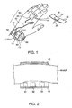
- Fig. 1 is an external view of a biological information measuring apparatus according to a first embodiment of the present invention.
- a pulse wave measuring device 1 biological information measuring apparatus
- the main body 10 comprises a watch case 11 with a built-in clock function, and a wristband 12 for holding this watch case 11 on the wrist.
- the surface of the watch case 11 has a liquid crystal display 13 for displaying, in addition to the current time and date, pulse wave information (biological information) based on a detection result from the sensor unit 30.
- a pulse wave signal Vm that is, the detection result from the sensor unit 30 is supplied.
- Body movement such as swinging the wrist is detected by the acceleration detector 60 as body movement signal Vt.
- the data processing circuit 50 processes the pulse wave signal Vm and body movement signal Vt to generate the pulse rate and other biological information.
- buttons 111 and 112 are also provided on the outside of the watch case 11 for setting the time, changing the display mode, and other operations.
- the power supply for the pulse wave measuring device 1 is a battery in the watch case 11.
- Cable 20 supplies power from the battery to the sensor unit 30, and enables detection results to be input from the sensor unit 30 to the data processing circuit 50 in the watch case 11.
- the sensor holding band 40 in this exemplary embodiment has a hook-and-loop fastener attached thereto so that, as shown in Fig. 1, it can hold sensor unit 30 tight to the base of the finger.
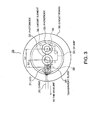
- a disk-shaped sensor unit 30 is fixed on the inside surface of the sensor holding band 40 such that light-emitting diode (referred to below as LED) 31 and photodiodes 32 and 33 are held facing the finger as illustrated in Fig. 2.
- LED 31 emits light to the finger, emitted light is absorbed by hemoglobin in the blood flowing through blood capillaries in the finger tissues, emitted light that is not absorbed is reflected by the tissue, and the reflected light is received by the photodiodes 32 and 33 and converted to an electrical signal according to the amount of received light.
- the sensor holding band 40 material is preferably one that does not pass light. Therefore, even when the pulse wave measuring device 1 is used outdoors, natural light will not be directly incident on the photodiodes 32 and 33.
- A-1-2 Configuration of the sensor unit 30
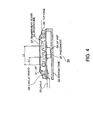
- Fig. 3 is a plan view of the sensor unit
- Fig. 4 is a section view of the sensor unit.
- the LED 31 and photodiodes 32 and 33 are formed on a surface of a circuit board 36.
- An opamp 34 and circuit element 35 are formed on the back of circuit board 36.
- the opamp 34 and circuit element 35 amplify the difference between the output signals from photodiodes 32 and 33. This is described further below.
- a top case 38 in which is held transparent glass 37 is formed around the edge of the top of circuit board 36. This transparent glass 37 protects LED 31 and photodiodes 32 and 33 while enabling the passage of light.
- a bottom case 39 having an opening for passing cable 20 is also formed on the back of circuit board 35.
- the LED 31 and photodiodes 32 and 33 are arranged in a line in this exemplary embodiment, and are more specifically arranged so that distance L1 is less than distance L2 (L1 ⁇ L2) where distance L1 is the distance from the light emitting center of LED 31 to the photodetection center of photodiode 32, and distance L2 is the distance from the light emitting center of LED 31 to the photodetection center of photodiode 33. That is, photodiode 33 is disposed so that the distance L2 from the photodetection center thereof to the light emitting center of the LED 31 is different from the distance L1 from the light emitting center of LED 31 to the photodetection center of photodiode 32. As a result, the optical path from LED 31 to photodiode 33 is longer than the path from LED 31 to photodiode 32.
- emitted light from LED 31 is also absorbed and dispersed by body tissues, and not just by hemoglobin in the blood, though there is some variance with wavelength. Therefore, once the path length reaches a certain length, emitted light is absorbed and dispersed by the transmission medium, that is, body tissues, and substantially no reflected light is incident on the photodiodes 32 and 33.
- distance L1 is determined so that there is little absorption and dispersion by tissue, and blood flow can be detected by the photodiode 32
- distance L2 is determined so that there is substantially no incidence of reflected light on photodiode 33.
- a pulse wave signal is therefore superposed on the output signal from photodiode 32, and a pulse wave signal does not appear in the output signal of photodiode 33.
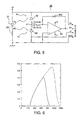
- Fig. 5 is a circuit diagram showing the electrical configuration of the sensor unit. As shown in the figure, the anode of the LED 31 is connected to positive power source +V, and the cathode is to ground through resistor 351. Resistor 351 operates as a current limiting resistor to assure that a desired current flows to LED 31.
- Fig. 8 shows the relationship between voltage and current at node X when the circuit is interrupted at point Y in Fig. 5. As shown in the figure, when the luminance incident on photodiode 32 increases as shown in the figure, current i1 increases, and when the luminance incident on photodiode 33 increases, current i2 decreases.
- the light incident on photodiodes 32 and 33 includes outside light in addition to the emitted light of LED 32 reflected light by the tissues.
- outside light in addition to the emitted light of LED 32 reflected light by the tissues.
- the luminance (intensity) of outside light incident on the photodiodes 32 and 33 is equal if the distance between the photodiodes 32 and 33 is short. In this exemplary embodiment, therefore, the relative positions of the photodiodes 32 and 33 are determined so that the luminance (intensity) of outside light is equal.
- pulse wave signal Vm is dependent on the luminance Pa of reflected light incident on photodiode 32.
- A-1-3 Configuration of the data processing circuit 50
- Fig. 10 is a block diagram of the functions of a data processing circuit.
- reference numeral 51 is a pulse wave signal converter for converting pulse wave signal Vm from sensor unit 30 from an analog signal to a digital signal, and outputting it as pulse wave data MD
- 52 is a body movement signal converter for converting body movement signal Vt from an analog signal to a digital signal, and outputting it as body movement data TD
- 53 is RAM or other memory for storing pulse wave data MD and body movement data TD.
- Reference numeral 54 is a pulse wave frequency analyzer for generating pulse wave analysis data MKD by frequency analyzing pulse wave data MD read from memory 53; and 55 is a body movement frequency analyzer for generating body movement analysis data TKD by frequency analyzing body movement data TD read from memory 53.
- Various methods can be used for this frequency analysis.
- the present exemplary embodiment uses a fast Fourier transform (FFT) because analysis can be completed in a short operating time.
- FFT fast Fourier transform
- Reference numeral 56 is a pulse wave component extractor for generating pulse wave analysis data after body movement component removal MKD', that is, pulse wave analysis data MKD from which the body movement component has been removed, based on pulse wave analysis data MKD and body movement analysis data TKD. More specifically, it removes the spectrum frequency component corresponding to the spectrum frequencies of body movement analysis data TKD from the spectrum frequency components of pulse wave analysis data MKD to generate pulse wave analysis data after body movement component removal MKD'.
- Reference numeral 57 is a pulse rate calculator for determining the fundamental frequency Fml of the pulse wave component based on the pulse wave analysis data after body movement component removal MKD', and calculating 60/Fml to generate pulse rate HR. Pulse rate HR is thus supplied to liquid crystal display 13, and displayed. The user can thus know his or her own pulse rate even while jogging or exercising.
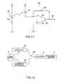
- Fig. 11 is a circuit diagram of a comparative sensor unit 30' prepared for comparative purposes.
- This comparative sensor unit 30' is the sensor unit 30 shown in Fig. 5 without photodiode 33, and is equivalent to a conventional sensor unit.
- Fig. 12 is a block diagram of the system used for this comparison test.
- comparative sensor unit 30' and sensor unit 30 were worn at the base of a finger, and exposed to light emitted from a noise source N at a frequency of 2.2 Hz with a 5000 lux luminance difference as outside light noise. More specifically, noise source N was controlled to switch a 5000 lux light on and off at a 2.2 Hz frequency.
- the output signals from comparative sensor unit 30' and sensor unit 30 were then switched using switch SW, amplified by an amplifier A with a gain of approximately 6000, and the amplified signals were analyzed by frequency analyzer S.
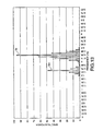
- Fig. 13 shows the results of analysis of the output signal from comparative sensor unit 30'
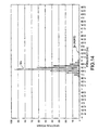
- Fig. 14 shows the results of analysis of the output signal from sensor unit 30.
- the output signal of comparative sensor unit 30' is affected by outside light, and has a noise spectrum Sn near 2.2 Hz.
- the pulse wave spectrum Sm is at approximately 1.7 Hz.
- the power of pulse wave spectrum Sm is only half that of noise spectrum Sn. Therefore, if comparative sensor unit 30' is used in pulse wave measuring device 1, noise spectrum Sn will be falsely detected with pulse wave spectrum Sm, and a false pulse rate HR will be calculated.
- a pulse wave measuring device 1 using this sensor unit 30 can calculate pulse rate HR based on an accurate pulse wave spectrum Sm.
- Fig. 15 is a graph of the measured results.
- the vertical axis in this graph is relative power Q (noise spectrum power/pulse wave spectrum power + noise spectrum power), and the horizontal axis is the luminance difference of noise source N. Because the noise component decreases as relative power Q decreases, the pulse wave spectrum Sm can be accurately detected.
- the output signal of sensor unit 30 is completely unaffected by noise, regardless of the noise spectrum power. This means that even outdoors in midsummer, the pulse wave spectrum Sm can be accurately detected without being affected by outside light.
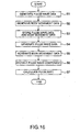
- the pulse wave signal converter 51 converts pulse wave signal Vm from an analog signal to a digital signal to generate pulse wave data MD (step S1)
- body movement signal converter 52 converts body movement signal Vt from an analog signal to a digital signal to generate body movement data TD (step S2).
- Memory 53 stores pulse wave data MD and body movement data TD (step S3).
- the body movement frequency analyzer 55 applies a fast Fourier transform process to the body movement data MD read from memory 53 to generate body movement analysis data TKD (step S5).
- body movement analysis data TKD is shown in Fig. 17 (b).
- the spectrum frequencies of the body movement analysis data TKD in this case match the spectrum frequencies associated with the body movement component of pulse wave analysis data MKD. It should be noted that while the spectrum frequencies match in this case, they can also differ. This is because while body movement signal TH is detected directly as acceleration caused by, for example, swinging the arm, blood flow is affected by, for example, blood vessels and tissues.
- the pulse wave component extractor 55 removes the spectrum frequency components corresponding to each spectrum frequency of body movement analysis data TKD from the spectrum frequency components of pulse wave analysis data MKD to generate the pulse wave analysis data after body movement component removal MKD'. It is therefore possible by means of this process to remove the body movement component from pulse wave analysis data MKD and extract the pulse wave component even if the spectrum power of the body movement component differs in the pulse wave analysis data MKD and body movement analysis data TKD. For example, if the pulse wave analysis data MKD and body movement analysis data TKD are as shown in Fig. 17 (a) and (b), pulse wave analysis data after body movement component removal MKD' will be as shown in Fig. 17 (c).
- the pulse rate calculator 57 identifies the fundamental frequency Fm1 of the pulse wave component based on pulse wave analysis data after body movement component removal MKD', and calculates 60/Fm1 to generate the pulse rate HR.
- the fundamental frequency Fm1 of the pulse wave component is obtained by determining the frequency with the greatest spectrum power in the pulse wave analysis data after body movement component removal MKD'. More specifically, spectrum power is compared in sequence to find the greatest. For example, if pulse wave analysis data after body movement component removal MKD' is as shown in Fig. 17 (c), F1 is identified as the fundamental frequency Fm1 of the pulse wave component.
- the effects of outside light can be reliably cancelled using a simple design because the distance between LED 31 and photodiodes 32 and 33 is different and both photodiodes 32 and 33 are placed where outside light is equally incident.
- the pulse wave measuring device 1 can be used outside in the middle of summer.
- the pulse rate HR can be detected even while running or otherwise exercising because the pulse wave signal Vm is frequency analyzed to remove the body movement component. As a result, a user can monitor his or her own health while running, and can thus train more effectively.
- a body movement measurement device detects body movement using a reflection type optical sensor (sensor unit 300 described below) comprising a photodetection means and light emitting means.
- Part of the light emitted from light emitting means A1 is absorbed by body tissues and hemoglobin in the blood, and another part is reflected by body tissue with the reflected light detected by the photodetection means B1.
- the photodetection means B1 outputs an output signal corresponding to the amount of detected light. Absorption by body tissues and absorption by hemoglobin in the blood are thus reflected in the output signal of the photodetection means B1.
- the tissue absorption component I2 is constant because the tissue density does not change.
- the venous blood absorption component I3 is also constant. This is because there is no pulse in the veins, and there is therefore no change in density. This is shown in Fig. 22, from which it will be known that the pulse of blood pumped from the heart gradually dissipates, and has completely disappeared in the veins.
- the output signal of the photodetection means B1 cannot, therefore, be used as a body movement signal by simply emitting light to the blood vessels C and detecting reflected light therefrom using the photodetection means B1 because there is variation in the arterial blood absorption component I4 regardless of whether there is body movement.
- Fig. 23 shows the molecular extinction coefficient of reduced hemoglobin Hb and oxygenated hemoglobin HbO 2 .
- oxygenated hemoglobin HbO 2 is present primarily in arterial blood, and reduced hemoglobin Hb is present in venous blood. It is therefore possible to observe the pulse-related absorption component by considering only absorption by oxygenated hemoglobin HbO 2 because there is no pulse in venous blood as noted above.
- the extinction coefficient of oxygenated hemoglobin HbO 2 drops sharply above 600 nm. On the other hand, tissue absorption does not drop even above 600 nm.
- a body movement measurement device is the same as a pulse wave measuring device 1 according to the first embodiment of the invention shown in Fig. 1.
- sensor unit 300 is used in this second embodiment in place of sensor unit 30 in the first embodiment.
- This sensor unit 300 is comprised to convert reflected light in the wavelength range of 600 nm and above to an electrical signal such that a body movement signal Vt indicative of the amount of body movement is output from sensor unit 30. Therefore, an acceleration detector 60 is not provided inside main body 10.
- the data processing circuit 50 provided in the main body 10 applies a fast Fourier transform process to the body movement signal Vt, and analyzes the result of this process to calculate pitch P.
- the mechanical configuration of sensor unit 300 in this second embodiment of the invention is the same as that of the sensor unit 30 in the first embodiment except that LED 310 is used in place of LED 31 (light emitting means). Therefore, the relative positions of the LED 310 and photodiodes 32 and 33 are those resulting from replacing LED 31 in Fig. 3 and Fig. 4 with LED 310.
- the spectral sensitivity characteristics of photodiodes 32 and 33 are as indicated by the solid line in Fig. 6.
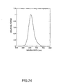
- the light emitting characteristic of the LED 310 is as shown in Fig. 24. Measurement by the sensor unit 300 therefore occurs in the wavelength range where the photodiode characteristics and LED characteristics overlap, that is, in the range 630 nm to 690 nm with a center wavelength of 660 nm.
- absorption by oxygenated hemoglobin HbO 2 is reduced in the 630 nm to 690 nm wavelength range.
- the pulse wave component is suppressed, and the body movement component accounts for the majority of the output signals of photodiodes 32 and 33.
- the LED 310 and photodiodes 32 and 33 are arranged in this embodiment in the same way as in the first embodiment (see Fig. 3 and Fig. 4). As a result, the optical path from LED 310 to photodiode 33 is longer than the path from LED 310 to photodiode 32.
- Emitted light from LED 310 is absorbed and dispersed by body tissues, but as the path length increases, substantially all emitted light becomes absorbed by the transmission medium, that is, the body tissues. Therefore, when the path length is long, there is substantially no reflected light incident on photodiodes 32 and 33.
- distance L1 shown in Fig. 3 is determined so that there is relatively little absorption and dispersion by the tissues, and tissue movement can be detected by photodiode 32.
- distance L2 shown in the same figure is determined so that there is substantially no reflected light incident on photodiode 33. Therefore, the output signal of photodiode 32 reflects tissue variations due to body movement, but there is no body movement waveform in the output signal of the photodiode 33.
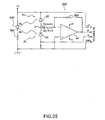
- Fig. 25 is a circuit diagram of the sensor unit 300. This sensor unit 300 differs from sensor unit 30 shown in Fig. 5 in that LED 31 is replaced by LED 310, and opamp 34 outputs body movement signal Vt.
- distance L2 from LED 310 to photodiode 33 is determined so that there is substantially no incidence of light from LED 310.
- luminance Pb is extremely low relative to luminance Pa.
- body movement signal Vt is dependent on the luminance Pa of reflected light incident on photodiode 32.
- a sensor unit 300 thus comprised is held at the base of a finger by sensor holding band 40 as shown in Fig. 5, LED 310 and photodiodes 32 and 33 are held with the light emitting surface and photodetecting surfaces thereof facing the surface of the finger.
- LED 310 then emits light to the finger while thus positioned, light reflected from the body is detected by photodiodes 32 and 33.
- the outside light components are mutually cancelled. It is therefore possible to input only a body movement signal Vt indicative of body movement through cable 20 to main body 10.
- the data processing circuit 500 in this second embodiment is described next with reference to Fig. 26. It should be noted that data processing circuit 500 is housed inside main body 10 as in the first embodiment.
- the data processing circuit 500 also specifically comprises CPU, RAM as working memory for the CPU, and ROM storing a program for achieving the above-noted function blocks.
- pitch calculator 540 calculates pitch P based on spectrum power in the body movement analysis data TKD, and outputs the calculated result to the LCD.
- This pitch calculator 54 comprises signal identifier 541, first wave identifier 542, second wave identifier 543, and signal discriminator 544.
- the signal specifier 541 selects a signal with a power level exceeding a specific threshold in a range above a specific frequency as a reference wave.
- the first wave identifier 542 determines whether there is a high level signal with a frequency equivalent to 1/3 the reference wave frequency.
- the second wave identifier 543 determines whether there is a high level signal with a frequency equivalent to 2/3 the reference wave frequency.
- signal discriminator 544 identifies the reference wave as the second harmonic of the fundamental wave of body movement. In addition, if the second wave identifier 543 determines that there is not a high level signal at a frequency position equivalent to 2/3 the reference wave frequency, the signal discriminator 544 identifies the reference wave as the second harmonic of the fundamental wave of body movement.
- the reference wave is only determined to be the third harmonic of the fundamental wave if the reference wave is determined to equal or exceed a specific frequency level. However, if the reference wave is determined to be below the frequency level of the process, the signal discriminator 544 determines the reference wave to be the second harmonic of the fundamental wave.
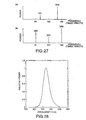
- Fig. 27 (a) is a typical spectrum when the user is running.
- spectrum line SA1 corresponding to the fundamental wave of body movement
- spectrum line SA2 equivalent to the second harmonic of the fundamental wave of body movement
- the level of spectrum line SA2 equivalent to the second harmonic component is significantly higher than spectrum line SA1 corresponding to the fundamental wave.
- the fundamental wave of arm swinging (equivalent to SA1) is equivalent to a pendulum action of which the out-swing and return of the arm is one period.
- Spectrum line SB1 corresponding to the fundamental wave of body movement, spectrum line SB2 corresponding to the second harmonic, and spectrum line SB3 corresponding to the third harmonic appear when the user is walking. There is not as much up and down movement when walking as there is when running, and the signal component attributable to arm swinging is relatively strong. This characteristic appears in spectrum line SB1 corresponding to the fundamental wave. As a result, the ratio between spectrum lines SB1, SB2, and SB3 is not constant. However, compared with running, the levels of spectrum line SB1 and spectrum line SB3 are higher than the level of spectrum line SB2.
- the pitch calculator 540 is thus comprised to use the difference in the spectrum patterns when running and walking to obtain the pitch P.
- sensor unit 300 The operation of sensor unit 300 is first described in comparison with the operation of a comparative sensor unit.
- the LED 31 having light emitting characteristics as shown in Fig. 24 was replaced with LED 310' having light emitting characteristics as shown in Fig. 28.
- the light emitting characteristic of LED 310' has a peak wavelength at 525 nm with a peak width at half height of approximately 40 nm. That is, comparative sensor unit 300' obtains measurements in a wavelength range where the absorption characteristic of oxygenated hemoglobin HbO 2 is great. (See Fig. 23.)
- Fig. 28 is a graph of an output signal wave WF1 from comparative sensor unit 300' and the frequency analysis thereof.
- St1 is the spectrum line corresponding to the fundamental wave of the body movement component, and has a frequency of 1.1 Hz.
- St2 is the spectrum line corresponding to the second harmonic of the body movement component, and has a frequency of 2.2 Hz.
- Sm is the spectrum line corresponding to fundamental wave of the pulse wave component.
- the wavelength range used for measurements is set below 600 nm, emitted light is absorbed by oxygenated hemoglobin HbO 2 and the pulse of arterial blood is measured as spectrum line Sm. Because the power of pulse wave spectrum Sm is greater than spectrum lines St1 and St2 related to the body movement component, the fundamental wave of body movement is falsely detected, and an accurate pitch P therefore cannot be detected.
- the LED 310 used in this example has a light emitting characteristic with a peak wavelength at 660 nm and a peak width at half height of 40 nm as shown in Fig. 24.
- the body movement signal Vt can be detected with a high S/N ratio even when used running or otherwise exercising outdoors.
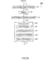
- the body movement signal converter 52 of the data processing circuit 500 converts the body movement signal Vt from an analog signal to a digital signal to generate body movement data TD.
- This body movement data TD is stored to the memory 53, and is read from the memory 53 at a specific timing.
- the body movement frequency analyzer 55 applies a FFT process to the body movement data TD read from memory 53 to generate body movement analysis data TKD.
- the pitch calculator 540 then calculates pitch P based on the spectra in body movement analysis data TKD.
- step ST3 If the frequency of the reference wave is less than 100 times/minute, a different candidate is selected in step ST3. Then, in step ST4, the signal with the highest level is selected from the other signals not including the previous [candidate] signal as the reference wave. In this process, the pitch is used as is as the current pitch (step ST5), and in step ST6 this value is defined as the pitch.
- step ST7 it is determined whether there is a signal with a frequency 1/3 the frequency of this reference wave and an amplitude at least 1/2 the amplitude of the reference wave.
- step ST7 If in step ST7 there is not a signal with a frequency 1/3 the frequency of this reference wave and an amplitude at least 1/2 the amplitude of the reference wave, the procedure advances to step ST8.
- step ST8 it is determined whether there is a signal with a frequency 2/3 the frequency of this reference wave and an amplitude at least 1/2 the amplitude of the reference wave.
- step ST9 it is determined whether the frequency of this reference wave is 150 times/minute or greater. This value of 150 times/minute is 1.5 times 100 times/minute.
- the pitch while walking is normally in the range from 100 times/minute to 150 times/minute, and the pitch while running is 150 times/minute to 200 times/minute. It is therefore possible to use the value of 150 times/minute as the dividing line for confirming whether the user is walking or running. If it is determined in step ST9 that the frequency of the reference wave is 150 times/minute or greater, the reference wave is determined to be equivalent to the third harmonic. As a result, in step ST10, the frequency of this signal is multiplied by 2/3, and the resulting 2/3 value is confirmed as the pitch in step ST6.
- step ST7 If in step ST7 there is not a signal with a frequency 1/3 the frequency of this reference wave and an amplitude at least 1/2 the amplitude of the reference wave, the procedure advances to step ST8. If in step ST8 there is a signal with a frequency 2/3 the frequency of this reference wave and an amplitude at least 1/2 the amplitude of the reference wave,the procedure advances to step ST9. If in step ST9 it is determined that the frequency of this reference wave is 150 times/minute or greater, this reference wave can be confirmed to be the third harmonic of the fundamental wave when walking. Furthermore, because the reference wave can be confirmed to be a signal equivalent to the third harmonic, the frequency of this signal is multiplied by 2/3 in step ST 10, and the resulting 2/3 value is confirmed as the pitch in step ST6.
- step ST9 the frequency of the reference wave is less than 150 times/minute, the reference wave can be determined as not a signal equivalent to the third harmonic. Therefore, any signal with a frequency that is 1/3 or 2/3 the frequency of this reference wave can be determined to be noise, and the reference wave can be determined to be the second harmonic component. Therefore, this value is defined as the pitch at step ST6.
- the reference wave can only be determined to be the third harmonic if the frequency of the reference wave is 150 times/minute or greater.
- the wavelength range used for measuring the body movement signal Vt is set to 600 nm or above in sensor unit 300, pulse components in the detection signal can be sufficiently suppressed, and body movement signal Vt can be detected with a good S/N ratio. Moreover, because the effects of outside light are cancelled by the two photodiodes 32 and 33, an accurate body movement signal Vt can be detected even while exercising outdoors.
- the extinction coefficient of oxygenated hemoglobin HbO 2 decreases particularly from 600 nm to 900 nm. Therefore, it is particularly desirable for the wavelength range used for measurement to be set in the range from 600 nm to 900 nm. It should be noted that the wavelength range used for measurement can also be limited by using a filter.
- Fig. 32 is a section view of a biological information measuring apparatus according to a third embodiment of the present invention.
- this biological information measuring apparatus has a wristwatch design.
- sensor unit 301 corresponding to sensor unit 30 in the first embodiment is formed integrally with the main body on the back side of watch case 11.
- a wristband 12 is attached to the watch case 11 for holding it on the arm; when the wristband 12 is wrapped around the wrist, the back side of the watch case 11 is held tight to the back of the wrist.
- Transparent glass 137 held by back cover 154 is disposed on the back side of watch case 11. This transparent glass 137 protects sensor unit 301.
- transparent glass 137 passes emitted light from LEDs 310 and 311, and passes light reflected through the body.
- the surface of the watch case 11 has a liquid crystal display 13 for displaying, in addition to the current time and date, biological information such as the pulse rate HR based on a detection result from the sensor unit 301.
- a data processing circuit 501 comprising various ICs, including a CPU, on a main circuit board 151.
- a battery 152 is provided on the back side of the main circuit board 151; power is supplied from the battery 152 to the liquid crystal display 13, main circuit board 151, and sensor unit 301.
- the main circuit board 151 and sensor unit 301 are connected by a heat seal 153.
- Wiring formed in the heat seal 153 carries power from the main circuit board 151 to the sensor unit 301, and carries a pulse wave signal Vm from sensor unit 301 to main circuit board 151.
- the data processing circuit 501 applies a FFT process to the pulse wave signal Vm, and analyzes the result of this process to calculate the pulse rate HR.
- buttons 111 and 112 are also provided on the outside of the watch case 11 for setting the time, changing the display mode, and other operations as in the pulse wave measuring device shown in Fig. 1.
- Fig. 33 is a plan view from the back of the sensor unit 301. As shown in Fig. 33, LEDs 310 and 311 and photodiodes 32 and 33 are disposed on the back side of circuit board 36, on the top side of which are opamp 34 and circuit element 35 (see Fig. 32). The opamp 34 and circuit element 35 function as a difference operator for amplifying the difference between the output signals from photodiodes 32 and 33. This is described further below.
- the spectral sensitivity characteristics of the photodiodes 32 and 33 in this exemplary embodiment are the same as those of the first and second embodiments as shown in Fig. 6.
- the light emitting characteristic of LED 310 is the same as in the second embodiment as shown in Fig. 24.
- the light emitting characteristic of-LED 311 is as shown in Fig. 28. That is, LED 31 has a light emitting characteristic with a peak wavelength at 660 nm with a peak width at half height of 40 nm, and LED 311 has a light emitting characteristic with a peak wavelength at 525 nm with a peak width at half height of 40 nm.
- LED 310 which emits light with a wavelength of 600 nm or above, is used as the light emitting means for body movement detection, and LED 311, which emits light with a wavelength below 600 nm, is used as the light emitting means for blood flow detection.
- photodiode 33 is placed so that the distance L2 from the photodetection center thereof to the light emitting center of LED 310 is different from distance L1 from the light emitting center of LED 310 to the photodetection center of photodiode 32, and so that L1' is different from L2'.
- the path length from LED 310 to photodiode 33 is longer than the path length from LED 310 to photodiode 32.
- the path length from LED 311 to photodiode 32 is longer than the path length from LED 311 to photodiode 33.
- Pc is the amount of outside light incident on photodiode 33
- Pm is the amount of outside light corresponding to the pulse wave component of the reflected light
- Pt' is the amount of outside light corresponding to body movement
- Pc is the luminance of outside light incident on photodiode 32
- Pt is the luminance of reflected light (that is, luminance corresponding to body movement).
- Pc is used for the amount of outside light incident on both photodiodes 32 and 33 because the luminance of outside light passing through tissue is the same on photodiodes 32 and 33 because they are placed close together.
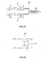
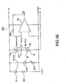
- Fig. 33 is a block diagram showing the electrical configuration of sensor unit 300. As shown in the figure, current i1 flows to photodiode 33, and current i2 flows to photodiode 32. The difference operator 340 subtracts current i2 from current i1, and outputs a voltage corresponding to this difference as pulse wave signal Vm. It should be noted that difference operator 340 can be achieved as a differential amplifier using an opamp and resistance (circuit element) as shown in Fig. 35, for example.
- im, it, it', and ic are the currents corresponding to luminance Pm, Pt, Pt', and Pc.
- pulse wave signal Vm output from difference operator 340 is obtained by the following equation where k is the current voltage conversion gain.
- the output signal of difference operator 340 can be used as a pulse wave signal Vm from which body movement has been removed.
- the mechanical configuration of a sensor unit 301 according to this second version is identical to that shown in Fig. 33, and in this exemplary embodiment, too, distances L1, L2 and L1' and L2' are set so that the effects of outside light are cancelled.
- Fig. 36 is a circuit diagram of a sensor unit 301 according to this second version.
- the sensor unit 301 in this figure differs from the sensor unit 300 shown in Fig. 25 in that LED 311 and resistor 351' are provided, and the positions of photodiode 32 and photodiode 33 are reversed.
- Fig. 35 If the directions of current i1 flowing to photodiode 33 and current i2 flowing to photodiode 32 are as shown in Fig. 35, i1 is positive and i2 is negative.
- Fig. 8 shows the relationship between voltage and current at node X when the circuit is interrupted at point Y. That is, if the luminance incident on photodiode 33 increases, current i1 increases, and when the luminance incident on photodiode 33 increases, current i2 decreases.
- the emission characteristics of LED 310 and LED 311 are set to detect a body movement component and pulse wave component, respectively, by focusing on the sharp drop in the absorption characteristic of oxygenated hemoglobin HbO 2 at 600 nm.
- this sensor unit 301 can obtain a pulse wave signal Vt from which the body movement component has been removed because the body movement component detected by photodiode 32 is removed from the detection signal from photodiode 33.
- the process obtaining this difference simultaneously cancels the outside light component, and a pulse wave signal Vt with a good S/N ratio can be obtained.
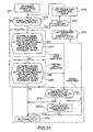
- the data processing circuit 501 is described next with reference to Fig. 37. It should be noted that data processing circuit 501 is housed inside main body 10 as in the first embodiment.
- the data processing circuit 501 also specifically comprises CPU, RAM as working memory for the CPU, and ROM storing a program for achieving the above-noted function blocks.
- pulse wave signal converter 51 converts pulse wave signal Vm from sensor unit 301 from an analog signal to a digital signal, and outputs the result as pulse wave data MD.
- the memory 53 stores pulse wave data MD for a specific period.
- the pulse wave frequency analyzer 54 frequency analyzes the pulse wave data MD read from memory 53 to generate pulse wave analysis data MKD.
- Various methods can be used for this frequency analysis.
- the present exemplary embodiment uses a fast Fourier transform (FFT) because analysis can be completed in a short operating time.
- FFT fast Fourier transform
- the pulse rate calculator 57 calculates the pulse rate HR based on spectrum power in pulse wave analysis data MKD, and outputs the result of the calculation to liquid crystal display 13.
- the pulse rate calculator 57 identifies the frequency Fh having the greatest spectrum power compared with the other spectrum lines. Because this frequency Fh is the fundamental frequency of the pulse wave signal Vm, the pulse rate calculator 57 obtains the pulse rate HR, which is the pulse count per minute, by calculating 60Fh.
- the pulse rate HR thus calculated is then displayed on the liquid crystal display 13.
- the S/N ratio of the pulse wave signal Vm is sufficiently high, it is possible to skip frequency analysis, simply wave shape the pulse wave signal Vm to convert it to a rectangular wave, obtain the period of this rectangular wave, and display the result as the pulse rate HR.
- a biological information measuring apparatus according to this third preferred embodiment of the present invention is described next.
- the user fastens the biological information measuring apparatus having a wristwatch design as shown in Fig. 32 to the wrist using wristband 12.
- a body movement component corresponding to, for example, arm swinging, is superposed to the blood flow through the blood vessels of the wrist.
- the LED 311 of the sensor unit 301 emits light with a peak wavelength of 525 nm to the back of the wrist, and light reflected through the body is detected by photodiode 33.
- LED 310 emits light with a peak wavelength of 660 nm to the back of the wrist, and light reflected through the body is detected by photodiode 32.
- the signal waveform WF1 detected by photodiode 33 and the frequency analysis result thereof are as shown in Fig. 29, and the signal waveform WF2 detected by photodiode 32 and the frequency analysis result thereof are as shown in Fig. 30, the signal waveform WF3 of the pulse wave signal Vm output from sensor unit 301 and the frequency analysis result thereof are as shown in Fig. 38.
- the level of the body movement components St1 and St2 superposed on the pulse wave signal Vm is significantly reduced compared with the body movement components St1 and St2 of the signal detected by photodiode 33 shown in Fig. 29.
- the sensor unit 301 can thus generate a pulse wave signal Vm with a good S/N ratio.
- the pulse wave signal Vm is supplied to the data processing circuit 501, the pulse wave signal Vm is converted from an analog signal to a digital signal by pulse wave signal converter 51, resulting in pulse wave data MD.
- the pulse wave data MD is sequentially stored to the memory 53, and then read out at a predetermined timing to the frequency analyzer 57.
- pulse wave frequency analyzer 54 applies a FFT process to the pulse wave data MD, performs a frequency analysis, and generates pulse wave analysis data MKD.
- the pulse rate calculator 57 identifies the spectrum having the highest spectrum power in the pulse wave analysis data MKD.
- the pulse rate calculator 57 then multiplies the frequency Fh of this spectrum by 60 to calculate the pulse rate HR, and this pulse rate HR is displayed on the liquid crystal display 13.
- the user can know his or her accurate pulse rate HR based on a pulse wave signal Vm from which body movement has been removed even while exercising.
- a user can monitor his or her own health while running, and can thus train more effectively.
- a biological information measuring apparatus it is therefore possible with a biological information measuring apparatus according to this third exemplary embodiment to obtain a pulse rate HR or other biological information using a single fast Fourier transform process instead of two FFT processes as are required with a conventional device because the difference operator 340 calculates the difference of the output signals from the photodiodes 32 and 33 to generate a pulse wave signal Vm in which a body movement component is suppressed.
- the overall configuration of the apparatus can be simplified, and the processing load on the CPU and other components can be reduced.
- the pulse rate HR for example, can be accurately measured even when exercising outdoors.
- the resistance of resistor r in the difference operator 340 of the sensor unit 300 shown in Fig. 34.
- the resistance of resistor 351 can be adjusted to vary luminance Pt associated with body movement.
- a pulse wave signal Vm with a suppressed body movement component is generated using a difference operator 340.
- a fast Fourier transform is then applied to the pulse wave signal to calculate the pulse rate HR.
- a biological information measuring apparatus addresses this by applying an autocorrelation function to the pulse wave signal Vm to suppress an irregular body movement component contained in the pulse wave signal Vm.
- An accurate pulse rate HR is then calculated by frequency analyzing the result of this pulse wave signal Vm autocorrelation operation.
- a biological information measuring apparatus is identical to the biological information measuring apparatus according to the third embodiment except for the addition of an autocorrelation operator 58 to the data processing circuit 501 of the third embodiment.
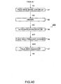
- Fig. 40 is a block diagram of a data processing circuit 502 according to this fourth embodiment.
- This data processing circuit 502 has an autocorrelation operator 58 between the memory 53 and pulse wave frequency analyzer 54.
- the autocorrelation operator 58 calculates an autocorrelation function described further below using the pulse wave data MD as input sample data to generate autocorrelated pulse wave data MD'.
- the waveform will become superimposed on itself when the period is shifted a particular integer multiple. If irregular variation x(t) has strong periodicity, shifting the wave an integer multiple of the period along the time base will produce a wave similar to the original. It is therefore possible to determine the similarity between a waveform shifted time ⁇ and the original waveform, and identify the period component of the change, by determining the correlation between x(t) and x(t+ ⁇ ).
- the autocorrelation function is defined as the average of the products of two variations offset by time ⁇ where x(t) is the irregular change relative to time, and is obtained by the following equation.
- C( ⁇ ) E[x(t)x(t+ ⁇ )] where E is the ensemble average, and can be substituted with a time average in a stationary stochastic process.
- the autocorrelation function C( ⁇ ) can therefore be expressed by the following equation.
- C( ⁇ ) lim 1/T fT/0 x(t)•x(t+ ⁇ )dt
- the above equation is the autocorrelation function C( ⁇ ) for a continuous signal.
- the autocorrelation function for discrete data is as follows.
- the autocorrelation operator 58 applies the product sum operation defined by the above equation to N pulse wave data MD(j) to generate autocorrelated pulse wave data MD'.
- This autocorrelated pulse wave data MD' is then compared with the pulse wave data MD to suppress the irregular body movement component and enhance the pulse wave component. It is therefore possible to increase the S/N ratio of the pulse wave analysis data MKD generated by the pulse wave frequency analyzer 54.
- the pulse rate calculator 57 can accurately identify the frequency of the pulse spectrum, and calculate an accurate pulse rate HR.
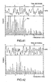
- Fig. 41 is a graph showing the output signal waveform WF4 of sensor unit 30 in this first comparison, and the frequency analysis result thereof.
- output signal waveform WF4 has slight periodicity.
- the power of pulse spectrum Sm is comparable to the power of other spectra. It is therefore not possible with this configuration to identify the frequency of the pulse spectrum Sm when there is also irregular body movement.
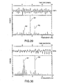
- Fig. 42 is a graph showing the output signal waveform WF5 of sensor unit 30 in this second comparison, and the frequency analysis result thereof. Because the center of the wavelength band in this case is 660 nm, the output signal waveform WF5 is indicative of a body movement component.
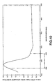
- FIG. 43 is a graph showing the output signal waveform WF6 of sensor unit 300 in this third comparison, and the frequency analysis result thereof.
- the sensor unit 300 suppresses the body movement component.
- the pulse wave component therefore appears enhanced in this output signal waveform WF6 when compared with the output signal waveform WF4 shown in Fig. 4.
- a spectrum with power equivalent to pulse spectrum Sm is also observed. It is therefore not possible with this configuration to identify the frequency of pulse spectrum Sm when there is also irregular body movement.
- a working version of the present embodiment applies the output signal waveform WF6 to the autocorrelation operator 58 as pulse wave data MD, and thus applies an autocorrelation function thereto to generate autocorrelated pulse wave data MD'.
- Fig. 44 is a graph showing the waveform WF7, which is indicative of the autocorrelated pulse wave data MD' in this working version, and the frequency analysis result thereof. It is known from this waveform WF7 that the body movement component is suppressed by applying an autocorrelation function, and a periodic pulse wave component is enhanced. It is also known from the frequency analysis of waveform WF7 that the power of pulse spectrum Sm is strongest when compared with the power of other spectra. It is therefore possible with this configuration to identify the frequency of the pulse spectrum Sm when there is also irregular body movement.
- the pulse rate calculator 57 can calculate a more accurate pulse rate HR.
- an autocorrelation operator 58 applies a process for enhancing a pulse wave component having a particular period.
- the pulse rate HR can therefore be calculated directly from the autocorrelated pulse wave data MD', and the pulse wave frequency analyzer 54 and pulse rate calculator 57 can be omitted.
- the autocorrelated pulse wave data MD' is compared with reference level data (equivalent to the dc level) to calculate the pulse wave period, and the pulse rate HR can then be calculated based on the result.
- This biological information measuring apparatus does not require frequency analysis, and can therefore be achieved using a CPU with a slow processor speed. Power consumption can therefore also be reduced because the processing load imposed by frequency analysis is not incurred.
- the present embodiment is therefore suitable for a low cost portable device.
- an autocorrelation function is applied by an autocorrelation operator 58.
- the calculating load of this autocorrelation function is great, however, because it is a product sum operation.
- the autocorrelation function is applied, however, to suppress irregular body movement components and enhance regular pulse wave components. Therefore, if the body movement component has a well defined period, suppression of the body movement component by the autocorrelation function is minimal.
- This fifth embodiment of the present invention addresses this by calculating the S/N ratio of the body movement signal Vt, and determining whether to apply an autocorrelation function based on the result.
- Fig. 45 is a block diagram for a data processing circuit 503 in this fifth embodiment of the present invention.
- the pulse wave signal Vm input to this data processing circuit 503 is generated, for example, by the sensor unit 300 in the third comparison described above in the fourth embodiment.
- the body movement signal Vt is generated, for example, by the sensor unit 30 in the second comparison described above in the fourth embodiment (where the center wavelength of LED emission is 660 nm).
- the pulse wave signal Vm is converted to a digital signal by the pulse wave signal converter 51, resulting in pulse wave data MD.
- the body movement signal Vt is converted to a digital signal by the body movement signal converter 52, resulting in body movement data TD.
- Pulse wave data MD and body movement data TD are stored to memory 53, and are read out at a specific timing.
- a S/N ratio evaluation means 59 evaluates the S/N ratio of the body movement data based on body movement analysis data TKD. More specifically, it first determines the spectrum with the highest level in the body movement analysis data TKD. Next, it calculates the S/N ratio of this spectrum. Next, it compares the calculated S/N ratio with a predefined reference value, and based on the result generates control signal CTL.
- the S/N ratio can be calculated using the following equation where L1, L2,... Ln represent each spectrum level, and Lmax is the highest spectrum level.
- S/N ratio sqr[L max 2 /(L1 2 + L2 2 + ... Ln 2 )]
- the resulting regular body movement increases the S/N ratio.
- Applying an autocorrelation function in this case has a minimal effect suppressing the body movement component.
- the S/N ratio drops because of the resulting irregular body movement.
- the autocorrelation function effectively suppresses the body movement component. It is therefore possible to determine whether or not to apply an autocorrelation function based on the S/N ratio.
- the above-noted reference value is set so that the desired effect is obtained by the autocorrelation function.
- the S/N ratio evaluation means 59 functions to detect the degree of body movement irregularity, and then based on the result determine whether or not to apply an autocorrelation function.
- the control signal CTL output from the S/N ratio evaluation means 59 is applied to the autocorrelation operator 58 and switch SW. Operation of the autocorrelation operator 58 is controlled by the control signal CTL.
- the autocorrelation operator 58 thus stops operating when the S/N ratio is high, and applies the autocorrelation function when the S/N ratio is low.
- the switch SW selects either pulse wave data MD or autocorrelated pulse wave data MD' based on the control signal CTL. When the S/N ratio is high, the switch SW outputs pulse wave data MD; when the S/N ratio is low, it outputs autocorrelated pulse wave data MD'.
- the autocorrelation function is applied only when the effect of the autocorrelation function operation will be significant.
- an autocorrelation function operation is applied based on the S/N ratio (degree of irregularity of body movement) of the body movement signal Vt in this fifth embodiment of the present invention, thereby reducing the processor load on the CPU and reducing power consumption.
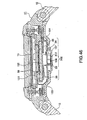
- Fig. 46 is a section view of a biological information measuring apparatus according to this preferred embodiment.
- a biological information measuring apparatus according to this sixth embodiment differs from a biological information measuring apparatus according to the third embodiment as shown in Fig. 32 in that LED 311 and photodiode 32 are removed from the sensor unit 302, an LED 312 is provided in place of LED 310, and a filter 138 is provided.
- the spectral sensitivity characteristic of photodiode 33 is shown in Fig. 6, that is, the photodiode 33 is sensitive in the wavelength range from 250 nm to 850 nm.
- the LED 312 is set to emit light in the wavelength range from 500 nm to 600 nm.
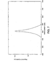
- the LED 312 in this case can have emission characteristics as shown in Fig. 7, for example.
- emissions may range from 550 nm to 650 nm, for example, such that part of the light is emitted in the range 500 nm to 600 nm.
- the transmission characteristic of the filter 138 is set so that the total wavelength range of light used for measurement by the measurement system from the LED 311 to the photodiode 33 is within the range 500 nm to 600 nm. For example, if the LED 312 emits light of a wavelength between 550 nm and 650 nm, the filter 138 passes light in the range 550 nm to 600 nm, and sufficiently attenuates light with a wavelength from 600 nm to 650 nm.
- FIG. 47 A circuit diagram showing the electrical configuration of sensor unit 302 is shown in Fig. 47.
- a current determined by the value of resistor 351' flows to the LED 312, and light is emitted.
- the emitted light passes the filter 138, whereby light is emitted to the wrist and absorbed by oxygenated hemoglobin HbO 2 in the blood stream. Unabsorbed light is reflected by body tissues. This reflected light passes back through the filter 138, and is incident on photodiode 33.
- the cathode of photodiode 33 is connected to positive power source +V, and the anode is connected to the negative input terminal of opamp 34.
- the positive input terminal of opamp 34 is to ground.
- the anode of photodiode 33 is to ground through a virtual short circuit.
- the photodiode 33 is thus reverse biased, and when light is incident thereon, current flows according to the amount of incident light.
- the opamp 34 and resistor 352 voltage convert and amplify the current from photodiode 33.
- the output signal of the opamp 34 thus varies according to the amount of incident light.
- the present inventors therefore, experimentally investigated the wavelength range suited to detecting a pulse wave component by varying the primary wavelength (peak wavelength) used for measurements in Japanese test subjects.
- the sensor unit of the embodiment was at the base of a finger and the back of the wrist, and the arms were swung at a pitch of 130 to simulate running.
- the detected pulse wave signal Vm was then frequency analyzed.
- the body movement component in this case will correspond to a pitch of 130. This fact was therefore used to determine from the results of the frequency analysis the spectrum estimated to be the pulse component and the spectrum estimated to be the body movement component.
- the ratio therebetween was then obtained and graphed in Figs. 48 and 48.
- the horizontal axis in both figures is the primary wavelength of light used for measurement, and the vertical axis is the ratio between the frequency spectrum height of the pulse component and the frequency spectrum height of the body movement component (pulse spectrum height/body movement spectrum height, the MT ratio below).
- the MT ratio the better the pulse wave detection characteristics.
- the wavelength range of light used for measurements is set in the range 500 nm to 600 nm in a biological information measuring apparatus according to this preferred embodiment having a wristwatch construction because the back of the wrist is the detection site for the pulse wave signal Vm.
- the measurement results described above were obtained with Japanese subjects, but similar results are obtained with Caucasians.
- measuring in the 500 nm to 600 nm range is even more preferable in blacks because even more melanin is present.
- a pulse wave signal Vm with a good S/N ratio can be obtained in the present embodiment because the pulse wave signal Vm is measured at the back of the wrist using light in the 500 nm to 600 nm wavelength range that is suitable for detecting a pulse wave component.
- an accurate pulse rate HR can be calculated even while exercising because the pulse rate HR is obtained using this pulse wave signal Vm.
- the back of the wrist is the detection site in the above sixth embodiment.
Landscapes
- Health & Medical Sciences (AREA)
- Life Sciences & Earth Sciences (AREA)
- Biomedical Technology (AREA)
- Heart & Thoracic Surgery (AREA)
- Veterinary Medicine (AREA)
- Biophysics (AREA)
- Pathology (AREA)
- Engineering & Computer Science (AREA)
- Cardiology (AREA)
- Physics & Mathematics (AREA)
- Medical Informatics (AREA)
- Molecular Biology (AREA)
- Surgery (AREA)
- Animal Behavior & Ethology (AREA)
- General Health & Medical Sciences (AREA)
- Public Health (AREA)
- Physiology (AREA)
- Measuring Pulse, Heart Rate, Blood Pressure Or Blood Flow (AREA)
Priority Applications (2)
| Application Number | Priority Date | Filing Date | Title |
|---|---|---|---|
| EP14163517.7A EP2756798A1 (fr) | 1997-09-05 | 1998-09-04 | Appareil de photodétection de type à réflexion et appareil de mesure d'informations biologiques |
| EP20140195523 EP2859842A1 (fr) | 1997-09-05 | 1998-09-04 | Appareil de photodétection de type à réflexion et appareil de mesure d'informations biologiques |
Applications Claiming Priority (5)
| Application Number | Priority Date | Filing Date | Title |
|---|---|---|---|
| JP24142697 | 1997-09-05 | ||
| JP24142697 | 1997-09-05 | ||
| JP30891397 | 1997-11-11 | ||
| JP30891397 | 1997-11-11 | ||
| EP98941717A EP0941694B1 (fr) | 1997-09-05 | 1998-09-04 | Procédé de configuration d'un capteur optique à réflexion |
Related Parent Applications (1)
| Application Number | Title | Priority Date | Filing Date |
|---|---|---|---|
| EP98941717A Division EP0941694B1 (fr) | 1997-09-05 | 1998-09-04 | Procédé de configuration d'un capteur optique à réflexion |
Related Child Applications (2)
| Application Number | Title | Priority Date | Filing Date |
|---|---|---|---|
| EP14163517.7A Division EP2756798A1 (fr) | 1997-09-05 | 1998-09-04 | Appareil de photodétection de type à réflexion et appareil de mesure d'informations biologiques |
| EP20140195523 Division EP2859842A1 (fr) | 1997-09-05 | 1998-09-04 | Appareil de photodétection de type à réflexion et appareil de mesure d'informations biologiques |
Publications (2)
| Publication Number | Publication Date |
|---|---|
| EP1444948A1 true EP1444948A1 (fr) | 2004-08-11 |
| EP1444948B1 EP1444948B1 (fr) | 2014-04-30 |
Family
ID=26535252
Family Applications (5)
| Application Number | Title | Priority Date | Filing Date |
|---|---|---|---|
| EP14163517.7A Withdrawn EP2756798A1 (fr) | 1997-09-05 | 1998-09-04 | Appareil de photodétection de type à réflexion et appareil de mesure d'informations biologiques |
| EP03078746.9A Expired - Lifetime EP1444948B1 (fr) | 1997-09-05 | 1998-09-04 | Dispositif de mesure optique pour diagnostic |
| EP20140195523 Withdrawn EP2859842A1 (fr) | 1997-09-05 | 1998-09-04 | Appareil de photodétection de type à réflexion et appareil de mesure d'informations biologiques |
| EP03078747A Expired - Lifetime EP1405593B1 (fr) | 1997-09-05 | 1998-09-04 | Dispositif de mesure optique pour diagnostic |
| EP98941717A Expired - Lifetime EP0941694B1 (fr) | 1997-09-05 | 1998-09-04 | Procédé de configuration d'un capteur optique à réflexion |
Family Applications Before (1)
| Application Number | Title | Priority Date | Filing Date |
|---|---|---|---|
| EP14163517.7A Withdrawn EP2756798A1 (fr) | 1997-09-05 | 1998-09-04 | Appareil de photodétection de type à réflexion et appareil de mesure d'informations biologiques |
Family Applications After (3)
| Application Number | Title | Priority Date | Filing Date |
|---|---|---|---|
| EP20140195523 Withdrawn EP2859842A1 (fr) | 1997-09-05 | 1998-09-04 | Appareil de photodétection de type à réflexion et appareil de mesure d'informations biologiques |
| EP03078747A Expired - Lifetime EP1405593B1 (fr) | 1997-09-05 | 1998-09-04 | Dispositif de mesure optique pour diagnostic |
| EP98941717A Expired - Lifetime EP0941694B1 (fr) | 1997-09-05 | 1998-09-04 | Procédé de configuration d'un capteur optique à réflexion |
Country Status (5)
| Country | Link |
|---|---|
| US (1) | US6198951B1 (fr) |
| EP (5) | EP2756798A1 (fr) |
| JP (1) | JP3689914B2 (fr) |
| DE (1) | DE69838286T2 (fr) |
| WO (1) | WO1999012469A1 (fr) |
Cited By (4)
| Publication number | Priority date | Publication date | Assignee | Title |
|---|---|---|---|---|
| US8740791B2 (en) | 2010-01-05 | 2014-06-03 | Seiko Epson Corporation | Biological information detector and biological information measurement device |
| CN104939812A (zh) * | 2014-03-27 | 2015-09-30 | 精工爱普生株式会社 | 生物体信息检测装置以及电子设备 |
| EP3087916A1 (fr) * | 2015-04-28 | 2016-11-02 | Nokia Technologies Oy | Capteur de mesure physiologique |
| EP3122244A4 (fr) * | 2014-03-27 | 2017-11-29 | Seiko Epson Corporation | Dispositif de détection d'informations biologiques, et appareil électronique |
Families Citing this family (182)
| Publication number | Priority date | Publication date | Assignee | Title |
|---|---|---|---|---|
| US6018673A (en) | 1996-10-10 | 2000-01-25 | Nellcor Puritan Bennett Incorporated | Motion compatible sensor for non-invasive optical blood analysis |
| US7890158B2 (en) | 2001-06-05 | 2011-02-15 | Lumidigm, Inc. | Apparatus and method of biometric determination using specialized optical spectroscopy systems |
| US6298252B1 (en) * | 1998-09-29 | 2001-10-02 | Mallinckrodt, Inc. | Oximeter sensor with encoder connected to detector |
| US6675031B1 (en) | 1999-04-14 | 2004-01-06 | Mallinckrodt Inc. | Method and circuit for indicating quality and accuracy of physiological measurements |
| US8224412B2 (en) | 2000-04-17 | 2012-07-17 | Nellcor Puritan Bennett Llc | Pulse oximeter sensor with piece-wise function |
| CA2405825C (fr) | 2000-04-17 | 2010-11-09 | Nellcor Puritan Bennett Incorporated | Capteur sphygmo-oxymetre avec fonction en pas a pas |
| US20040034285A1 (en) * | 2000-10-31 | 2004-02-19 | Takeshi Sahashi | Body movement analysis system and body movement analysis method |
| US6697658B2 (en) | 2001-07-02 | 2004-02-24 | Masimo Corporation | Low power pulse oximeter |
| DE60143115D1 (de) * | 2001-09-28 | 2010-11-04 | Csem Ct Suisse Electronique | Verfahren und Vorrichtung zur Pulsmessung |
| US6748254B2 (en) | 2001-10-12 | 2004-06-08 | Nellcor Puritan Bennett Incorporated | Stacked adhesive optical sensor |
| US6780158B2 (en) * | 2001-12-14 | 2004-08-24 | Nihon Kohden Corporation | Signal processing method and pulse wave signal processing method |
| FR2840794B1 (fr) * | 2002-06-18 | 2005-04-15 | Suisse Electronique Microtech | Equipement portable destine a la mesure et/ou la surveillance de la frequence cardiaque |
| US7190986B1 (en) | 2002-10-18 | 2007-03-13 | Nellcor Puritan Bennett Inc. | Non-adhesive oximeter sensor for sensitive skin |
| US20040171952A1 (en) * | 2003-02-28 | 2004-09-02 | Direction Technology Co. Ltd. | Mechanism of wireless heartbeat transmitter |
| JP3815448B2 (ja) * | 2003-03-19 | 2006-08-30 | セイコーエプソン株式会社 | 情報収集装置および脈拍計 |
| JP4515148B2 (ja) * | 2004-05-17 | 2010-07-28 | セイコーインスツル株式会社 | 生体情報計測装置及び生体情報計測方法 |
| US7222624B2 (en) * | 2004-07-02 | 2007-05-29 | Praxair Technology, Inc. | Dual sensor oxygen therapy device |
| US20060041198A1 (en) * | 2004-08-20 | 2006-02-23 | Matsushita Electric Industrial Co., Ltd. | Biological information arithmetic apparatus, biological information arithmetic method, computer-executable program, and recording medium |
| JP2008535540A (ja) | 2005-03-01 | 2008-09-04 | マシモ・ラボラトリーズ・インコーポレーテッド | 非侵襲的マルチパラメータ患者モニタ |
| US7657294B2 (en) | 2005-08-08 | 2010-02-02 | Nellcor Puritan Bennett Llc | Compliant diaphragm medical sensor and technique for using the same |
| US7657295B2 (en) | 2005-08-08 | 2010-02-02 | Nellcor Puritan Bennett Llc | Medical sensor and technique for using the same |
| US7590439B2 (en) | 2005-08-08 | 2009-09-15 | Nellcor Puritan Bennett Llc | Bi-stable medical sensor and technique for using the same |
| US20070038050A1 (en) * | 2005-08-12 | 2007-02-15 | Israel Sarussi | Device for use with reflective pulse oximetry |
| US20070060808A1 (en) | 2005-09-12 | 2007-03-15 | Carine Hoarau | Medical sensor for reducing motion artifacts and technique for using the same |
| US8092379B2 (en) | 2005-09-29 | 2012-01-10 | Nellcor Puritan Bennett Llc | Method and system for determining when to reposition a physiological sensor |
| US7904130B2 (en) | 2005-09-29 | 2011-03-08 | Nellcor Puritan Bennett Llc | Medical sensor and technique for using the same |
| US7899510B2 (en) | 2005-09-29 | 2011-03-01 | Nellcor Puritan Bennett Llc | Medical sensor and technique for using the same |
| US7869850B2 (en) | 2005-09-29 | 2011-01-11 | Nellcor Puritan Bennett Llc | Medical sensor for reducing motion artifacts and technique for using the same |
| US8233954B2 (en) | 2005-09-30 | 2012-07-31 | Nellcor Puritan Bennett Llc | Mucosal sensor for the assessment of tissue and blood constituents and technique for using the same |
| US7881762B2 (en) | 2005-09-30 | 2011-02-01 | Nellcor Puritan Bennett Llc | Clip-style medical sensor and technique for using the same |
| US7555327B2 (en) | 2005-09-30 | 2009-06-30 | Nellcor Puritan Bennett Llc | Folding medical sensor and technique for using the same |
| US8062221B2 (en) | 2005-09-30 | 2011-11-22 | Nellcor Puritan Bennett Llc | Sensor for tissue gas detection and technique for using the same |
| US7486979B2 (en) | 2005-09-30 | 2009-02-03 | Nellcor Puritan Bennett Llc | Optically aligned pulse oximetry sensor and technique for using the same |
| US7483731B2 (en) | 2005-09-30 | 2009-01-27 | Nellcor Puritan Bennett Llc | Medical sensor and technique for using the same |
| GB0607270D0 (en) | 2006-04-11 | 2006-05-17 | Univ Nottingham | The pulsing blood supply |
| TW200740409A (en) * | 2006-04-18 | 2007-11-01 | Wei-Kung Wang | A physiological signals monitor with digital real time calibration |
| US8073518B2 (en) | 2006-05-02 | 2011-12-06 | Nellcor Puritan Bennett Llc | Clip-style medical sensor and technique for using the same |
| EP1881379A1 (fr) * | 2006-07-19 | 2008-01-23 | ETA SA Manufacture Horlogère Suisse | Pièce d'horlogerie électronique comportant une cloison rapportée et procédé d'assemblage associé |
| JP4885637B2 (ja) * | 2006-07-27 | 2012-02-29 | セイコーインスツル株式会社 | 腕装着型電子歩数計 |
| US8145288B2 (en) | 2006-08-22 | 2012-03-27 | Nellcor Puritan Bennett Llc | Medical sensor for reducing signal artifacts and technique for using the same |
| US8219170B2 (en) | 2006-09-20 | 2012-07-10 | Nellcor Puritan Bennett Llc | System and method for practicing spectrophotometry using light emitting nanostructure devices |
| US8190225B2 (en) | 2006-09-22 | 2012-05-29 | Nellcor Puritan Bennett Llc | Medical sensor for reducing signal artifacts and technique for using the same |
| US8396527B2 (en) | 2006-09-22 | 2013-03-12 | Covidien Lp | Medical sensor for reducing signal artifacts and technique for using the same |
| US8175671B2 (en) | 2006-09-22 | 2012-05-08 | Nellcor Puritan Bennett Llc | Medical sensor for reducing signal artifacts and technique for using the same |
| US7869849B2 (en) | 2006-09-26 | 2011-01-11 | Nellcor Puritan Bennett Llc | Opaque, electrically nonconductive region on a medical sensor |
| US7574245B2 (en) | 2006-09-27 | 2009-08-11 | Nellcor Puritan Bennett Llc | Flexible medical sensor enclosure |
| US7890153B2 (en) | 2006-09-28 | 2011-02-15 | Nellcor Puritan Bennett Llc | System and method for mitigating interference in pulse oximetry |
| US7796403B2 (en) | 2006-09-28 | 2010-09-14 | Nellcor Puritan Bennett Llc | Means for mechanical registration and mechanical-electrical coupling of a faraday shield to a photodetector and an electrical circuit |
| US7684842B2 (en) | 2006-09-29 | 2010-03-23 | Nellcor Puritan Bennett Llc | System and method for preventing sensor misuse |
| US8068891B2 (en) | 2006-09-29 | 2011-11-29 | Nellcor Puritan Bennett Llc | Symmetric LED array for pulse oximetry |
| US8175667B2 (en) | 2006-09-29 | 2012-05-08 | Nellcor Puritan Bennett Llc | Symmetric LED array for pulse oximetry |
| US7680522B2 (en) | 2006-09-29 | 2010-03-16 | Nellcor Puritan Bennett Llc | Method and apparatus for detecting misapplied sensors |
| US7476131B2 (en) | 2006-09-29 | 2009-01-13 | Nellcor Puritan Bennett Llc | Device for reducing crosstalk |
| EP1908401A1 (fr) * | 2006-10-06 | 2008-04-09 | ETA SA Manufacture Horlogère Suisse | Méthode et dispositif de mesure d'une pulsation cardiaque lors de la pratique d'un sport rythmique |
| EP1908402B1 (fr) * | 2006-10-06 | 2015-12-09 | ETA SA Manufacture Horlogère Suisse | Méthode et dispositif intégré de mesure d'une pulsation cardiaque |
| JP2008132012A (ja) * | 2006-11-27 | 2008-06-12 | Denso Corp | 脈波検出装置 |
| JP5119654B2 (ja) * | 2006-12-07 | 2013-01-16 | セイコーエプソン株式会社 | 腕装着型生体情報計測機器 |
| US8652040B2 (en) | 2006-12-19 | 2014-02-18 | Valencell, Inc. | Telemetric apparatus for health and environmental monitoring |
| US8157730B2 (en) | 2006-12-19 | 2012-04-17 | Valencell, Inc. | Physiological and environmental monitoring systems and methods |
| US7894869B2 (en) | 2007-03-09 | 2011-02-22 | Nellcor Puritan Bennett Llc | Multiple configuration medical sensor and technique for using the same |
| US8280469B2 (en) | 2007-03-09 | 2012-10-02 | Nellcor Puritan Bennett Llc | Method for detection of aberrant tissue spectra |
| US8265724B2 (en) | 2007-03-09 | 2012-09-11 | Nellcor Puritan Bennett Llc | Cancellation of light shunting |
| JP5098380B2 (ja) * | 2007-03-14 | 2012-12-12 | セイコーエプソン株式会社 | 脈拍計測装置及びその制御方法 |
| JP4957354B2 (ja) * | 2007-04-23 | 2012-06-20 | 株式会社デンソー | 生体状態検出装置 |
| AT10035U1 (de) * | 2007-04-26 | 2008-08-15 | Neubauer Martin Dipl Ing | System zur mobilen erfassung und verarbeitung von vitalwerten an menschen und/oder tieren |
| EP2162059B1 (fr) | 2007-06-12 | 2021-01-13 | Sotera Wireless, Inc. | Moniteur de signaux vitaux et méthode pour mesurer la tension artérielle en utilisant des formes d'onde optique, électrique et de tension |
| US8602997B2 (en) * | 2007-06-12 | 2013-12-10 | Sotera Wireless, Inc. | Body-worn system for measuring continuous non-invasive blood pressure (cNIBP) |
| US11330988B2 (en) | 2007-06-12 | 2022-05-17 | Sotera Wireless, Inc. | Body-worn system for measuring continuous non-invasive blood pressure (cNIBP) |
| US11607152B2 (en) | 2007-06-12 | 2023-03-21 | Sotera Wireless, Inc. | Optical sensors for use in vital sign monitoring |
| JP2009074855A (ja) * | 2007-09-19 | 2009-04-09 | Oki Semiconductor Co Ltd | 光検出装置 |
| US20100274104A1 (en) * | 2007-10-09 | 2010-10-28 | Khan Sitara R | Infant/child monitor |
| US8251903B2 (en) * | 2007-10-25 | 2012-08-28 | Valencell, Inc. | Noninvasive physiological analysis using excitation-sensor modules and related devices and methods |
| US8352004B2 (en) | 2007-12-21 | 2013-01-08 | Covidien Lp | Medical sensor and technique for using the same |
| US8346328B2 (en) | 2007-12-21 | 2013-01-01 | Covidien Lp | Medical sensor and technique for using the same |
| US8366613B2 (en) | 2007-12-26 | 2013-02-05 | Covidien Lp | LED drive circuit for pulse oximetry and method for using same |
| US8577434B2 (en) | 2007-12-27 | 2013-11-05 | Covidien Lp | Coaxial LED light sources |
| US8442608B2 (en) | 2007-12-28 | 2013-05-14 | Covidien Lp | System and method for estimating physiological parameters by deconvolving artifacts |
| US8452364B2 (en) | 2007-12-28 | 2013-05-28 | Covidien LLP | System and method for attaching a sensor to a patient's skin |
| US8897850B2 (en) | 2007-12-31 | 2014-11-25 | Covidien Lp | Sensor with integrated living hinge and spring |
| US8199007B2 (en) | 2007-12-31 | 2012-06-12 | Nellcor Puritan Bennett Llc | Flex circuit snap track for a biometric sensor |
| US8070508B2 (en) | 2007-12-31 | 2011-12-06 | Nellcor Puritan Bennett Llc | Method and apparatus for aligning and securing a cable strain relief |
| US8092993B2 (en) | 2007-12-31 | 2012-01-10 | Nellcor Puritan Bennett Llc | Hydrogel thin film for use as a biosensor |
| US8437822B2 (en) | 2008-03-28 | 2013-05-07 | Covidien Lp | System and method for estimating blood analyte concentration |
| US8112375B2 (en) | 2008-03-31 | 2012-02-07 | Nellcor Puritan Bennett Llc | Wavelength selection and outlier detection in reduced rank linear models |
| DE102008022919A1 (de) * | 2008-05-09 | 2009-11-19 | Siemens Ag Österreich | Vorrichtung und Verfahren zur optimierten Pulsmessung |
| DE102008022920B4 (de) * | 2008-05-09 | 2010-05-12 | Siemens Ag Österreich | Vorrichtung zur Erkennung von Leblosigkeit |
| US7880884B2 (en) | 2008-06-30 | 2011-02-01 | Nellcor Puritan Bennett Llc | System and method for coating and shielding electronic sensor components |
| US7887345B2 (en) | 2008-06-30 | 2011-02-15 | Nellcor Puritan Bennett Llc | Single use connector for pulse oximetry sensors |
| US8071935B2 (en) | 2008-06-30 | 2011-12-06 | Nellcor Puritan Bennett Llc | Optical detector with an overmolded faraday shield |
| US20100004518A1 (en) | 2008-07-03 | 2010-01-07 | Masimo Laboratories, Inc. | Heat sink for noninvasive medical sensor |
| US8630691B2 (en) | 2008-08-04 | 2014-01-14 | Cercacor Laboratories, Inc. | Multi-stream sensor front ends for noninvasive measurement of blood constituents |
| US8364220B2 (en) | 2008-09-25 | 2013-01-29 | Covidien Lp | Medical sensor and technique for using the same |
| US8914088B2 (en) | 2008-09-30 | 2014-12-16 | Covidien Lp | Medical sensor and technique for using the same |
| US8423112B2 (en) | 2008-09-30 | 2013-04-16 | Covidien Lp | Medical sensor and technique for using the same |
| US8417309B2 (en) | 2008-09-30 | 2013-04-09 | Covidien Lp | Medical sensor |
| US20100145171A1 (en) * | 2008-12-05 | 2010-06-10 | Electronics And Telecommunications Research Institute | Apparatus for measuring motion noise robust pulse wave and method thereof |
| JP5470881B2 (ja) * | 2009-02-06 | 2014-04-16 | セイコーエプソン株式会社 | 測定装置及び測定方法 |
| US8788002B2 (en) | 2009-02-25 | 2014-07-22 | Valencell, Inc. | Light-guiding devices and monitoring devices incorporating same |
| JP5789199B2 (ja) | 2009-02-25 | 2015-10-07 | ヴァレンセル,インコーポレイテッド | ヘッドセット及びイアバッド |
| US9750462B2 (en) | 2009-02-25 | 2017-09-05 | Valencell, Inc. | Monitoring apparatus and methods for measuring physiological and/or environmental conditions |
| US8452366B2 (en) | 2009-03-16 | 2013-05-28 | Covidien Lp | Medical monitoring device with flexible circuitry |
| US8221319B2 (en) | 2009-03-25 | 2012-07-17 | Nellcor Puritan Bennett Llc | Medical device for assessing intravascular blood volume and technique for using the same |
| US8509869B2 (en) | 2009-05-15 | 2013-08-13 | Covidien Lp | Method and apparatus for detecting and analyzing variations in a physiologic parameter |
| US8634891B2 (en) | 2009-05-20 | 2014-01-21 | Covidien Lp | Method and system for self regulation of sensor component contact pressure |
| US11896350B2 (en) | 2009-05-20 | 2024-02-13 | Sotera Wireless, Inc. | Cable system for generating signals for detecting motion and measuring vital signs |
| US8475370B2 (en) * | 2009-05-20 | 2013-07-02 | Sotera Wireless, Inc. | Method for measuring patient motion, activity level, and posture along with PTT-based blood pressure |
| US8956294B2 (en) * | 2009-05-20 | 2015-02-17 | Sotera Wireless, Inc. | Body-worn system for continuously monitoring a patients BP, HR, SpO2, RR, temperature, and motion; also describes specific monitors for apnea, ASY, VTAC, VFIB, and ‘bed sore’ index |
| US9775529B2 (en) | 2009-06-17 | 2017-10-03 | Sotera Wireless, Inc. | Body-worn pulse oximeter |
| US8311601B2 (en) | 2009-06-30 | 2012-11-13 | Nellcor Puritan Bennett Llc | Reflectance and/or transmissive pulse oximeter |
| US8505821B2 (en) | 2009-06-30 | 2013-08-13 | Covidien Lp | System and method for providing sensor quality assurance |
| US9010634B2 (en) | 2009-06-30 | 2015-04-21 | Covidien Lp | System and method for linking patient data to a patient and providing sensor quality assurance |
| US8391941B2 (en) | 2009-07-17 | 2013-03-05 | Covidien Lp | System and method for memory switching for multiple configuration medical sensor |
| US8718736B2 (en) * | 2009-07-23 | 2014-05-06 | Covidien Lp | Physiological sensor with offset adhesive layer |
| US8417310B2 (en) | 2009-08-10 | 2013-04-09 | Covidien Lp | Digital switching in multi-site sensor |
| US8428675B2 (en) | 2009-08-19 | 2013-04-23 | Covidien Lp | Nanofiber adhesives used in medical devices |
| EP2292141B1 (fr) * | 2009-09-03 | 2015-06-17 | The Swatch Group Research and Development Ltd | Procédé et dispositif de mesure du pouls au moyen d'ondes lumineuses à deux longueurs d'onde |
| US11253169B2 (en) | 2009-09-14 | 2022-02-22 | Sotera Wireless, Inc. | Body-worn monitor for measuring respiration rate |
| US20110066043A1 (en) * | 2009-09-14 | 2011-03-17 | Matt Banet | System for measuring vital signs during hemodialysis |
| US8740807B2 (en) | 2009-09-14 | 2014-06-03 | Sotera Wireless, Inc. | Body-worn monitor for measuring respiration rate |
| US8527038B2 (en) * | 2009-09-15 | 2013-09-03 | Sotera Wireless, Inc. | Body-worn vital sign monitor |
| US10420476B2 (en) | 2009-09-15 | 2019-09-24 | Sotera Wireless, Inc. | Body-worn vital sign monitor |
| US20110066044A1 (en) | 2009-09-15 | 2011-03-17 | Jim Moon | Body-worn vital sign monitor |
| US10806351B2 (en) * | 2009-09-15 | 2020-10-20 | Sotera Wireless, Inc. | Body-worn vital sign monitor |
| JP5476922B2 (ja) * | 2009-10-27 | 2014-04-23 | セイコーエプソン株式会社 | 拍動検出装置及び拍動検出方法 |
| US8727977B2 (en) * | 2010-03-10 | 2014-05-20 | Sotera Wireless, Inc. | Body-worn vital sign monitor |
| US9173594B2 (en) | 2010-04-19 | 2015-11-03 | Sotera Wireless, Inc. | Body-worn monitor for measuring respiratory rate |
| US9339209B2 (en) | 2010-04-19 | 2016-05-17 | Sotera Wireless, Inc. | Body-worn monitor for measuring respiratory rate |
| US9173593B2 (en) | 2010-04-19 | 2015-11-03 | Sotera Wireless, Inc. | Body-worn monitor for measuring respiratory rate |
| US8747330B2 (en) | 2010-04-19 | 2014-06-10 | Sotera Wireless, Inc. | Body-worn monitor for measuring respiratory rate |
| US8888700B2 (en) | 2010-04-19 | 2014-11-18 | Sotera Wireless, Inc. | Body-worn monitor for measuring respiratory rate |
| US8979765B2 (en) | 2010-04-19 | 2015-03-17 | Sotera Wireless, Inc. | Body-worn monitor for measuring respiratory rate |
| US8386003B2 (en) * | 2010-05-05 | 2013-02-26 | Digio2 International Co., Ltd. | Portable medical device |
| US9237856B2 (en) | 2010-06-24 | 2016-01-19 | Pioneer Corporation | Light detecting apparatus and fluid measuring apparatus |
| US9113793B2 (en) | 2010-12-10 | 2015-08-25 | Rohm Co., Ltd. | Pulse wave sensor |
| US20140249432A1 (en) | 2010-12-28 | 2014-09-04 | Matt Banet | Body-worn system for continuous, noninvasive measurement of cardiac output, stroke volume, cardiac power, and blood pressure |
| US8888701B2 (en) | 2011-01-27 | 2014-11-18 | Valencell, Inc. | Apparatus and methods for monitoring physiological data during environmental interference |
| SG10201601164SA (en) | 2011-02-18 | 2016-03-30 | Sotera Wireless Inc | Modular wrist-worn processor for patient monitoring |
| US10357187B2 (en) | 2011-02-18 | 2019-07-23 | Sotera Wireless, Inc. | Optical sensor for measuring physiological properties |
| JP5682369B2 (ja) | 2011-02-23 | 2015-03-11 | セイコーエプソン株式会社 | 拍動検出装置 |
| US20130029681A1 (en) * | 2011-03-31 | 2013-01-31 | Qualcomm Incorporated | Devices, methods, and apparatuses for inferring a position of a mobile device |
| US9427191B2 (en) | 2011-07-25 | 2016-08-30 | Valencell, Inc. | Apparatus and methods for estimating time-state physiological parameters |
| EP2739207B1 (fr) | 2011-08-02 | 2017-07-19 | Valencell, Inc. | Systèmes et méthodes d'ajustement d'un filtre variable en fonction de la fréquence cardiaque |
| JP5909999B2 (ja) * | 2011-11-02 | 2016-04-27 | セイコーエプソン株式会社 | 脈波信号処理装置及び脈波計測装置 |
| DE112013000530T5 (de) | 2012-01-10 | 2014-10-02 | Maxim Integrated Products, Inc. | Plusfrequenz- und Blutsauerstoff-Überwachungesystem |
| JP6036122B2 (ja) * | 2012-02-02 | 2016-11-30 | セイコーエプソン株式会社 | 脈波測定装置及びプログラム |
| US20140073878A1 (en) * | 2012-09-11 | 2014-03-13 | Nellcor Puritan Bennett Llc | Methods and systems for determining physiological information using autocorrelation based on a modified signal |
| JP6500969B2 (ja) * | 2012-09-18 | 2019-04-17 | カシオ計算機株式会社 | 脈拍データ検出装置、脈拍データ検出方法、および脈拍データ検出プログラム |
| JP6251997B2 (ja) | 2012-09-18 | 2017-12-27 | カシオ計算機株式会社 | 脈拍データ検出装置、脈拍データ検出方法、および脈拍データ検出プログラム |
| CN102988036B (zh) * | 2012-12-26 | 2014-08-06 | 中国科学院自动化研究所 | 测量脉率的方法 |
| EP2931125A4 (fr) | 2013-01-28 | 2015-11-11 | Valencell Inc | Dispositifs de surveillance physiologique ayant des éléments de détection découplés d'un mouvement de corps |
| CN104055504A (zh) | 2013-03-18 | 2014-09-24 | 精工爱普生株式会社 | 生物体信息检测装置 |
| CN104055505B (zh) * | 2013-03-18 | 2019-03-22 | 精工爱普生株式会社 | 生物体信息检测装置 |
| CN104055508A (zh) | 2013-03-18 | 2014-09-24 | 精工爱普生株式会社 | 生物体信息检测装置 |
| FI126338B (en) * | 2013-05-15 | 2016-10-14 | Pulseon Oy | Portable heart rate monitor |
| JP6004995B2 (ja) * | 2013-06-21 | 2016-10-12 | 拓則 島崎 | 拍動検出装置 |
| JP2015039542A (ja) | 2013-08-22 | 2015-03-02 | セイコーエプソン株式会社 | 脈波測定装置 |
| CN105979855B (zh) | 2014-02-11 | 2019-05-28 | 苹果公司 | 检测正在穿戴可穿戴电子设备的肢体 |
| JP2016016203A (ja) * | 2014-07-10 | 2016-02-01 | セイコーエプソン株式会社 | 生体情報検出装置 |
| US20160029898A1 (en) | 2014-07-30 | 2016-02-04 | Valencell, Inc. | Physiological Monitoring Devices and Methods Using Optical Sensors |
| WO2016022295A1 (fr) | 2014-08-06 | 2016-02-11 | Valencell, Inc. | Modules à capteurs physiologiques optiques avec réduction du bruit de signal |
| JP5862731B1 (ja) * | 2014-08-27 | 2016-02-16 | セイコーエプソン株式会社 | センサー及び生体情報検出装置 |
| US9794653B2 (en) | 2014-09-27 | 2017-10-17 | Valencell, Inc. | Methods and apparatus for improving signal quality in wearable biometric monitoring devices |
| WO2016107171A1 (fr) * | 2014-12-31 | 2016-07-07 | 歌尔声学股份有限公司 | Procédé de mesure de signal d'impulsion du type photoéléctrique et dispositif de mesure |
| JP6510913B2 (ja) * | 2015-07-01 | 2019-05-08 | 浜松ホトニクス株式会社 | 血圧比算出装置、血圧比算出方法、血圧比算出プログラム、及びそのプログラムを記録する記録媒体 |
| EP3344127A4 (fr) | 2015-10-23 | 2018-07-25 | Valencell, Inc. | Dispositifs de surveillance physiologique et procédés d'identification de type d'activité chez un sujet |
| US10945618B2 (en) | 2015-10-23 | 2021-03-16 | Valencell, Inc. | Physiological monitoring devices and methods for noise reduction in physiological signals based on subject activity type |
| JP2016116947A (ja) * | 2016-03-28 | 2016-06-30 | セイコーエプソン株式会社 | 脈波信号処理装置及び脈波計測装置 |
| EP3454747A4 (fr) | 2016-05-09 | 2020-10-21 | Belun Technology Company Limited | Dispositif portable pour soins de santé et son procédé |
| US10285651B2 (en) * | 2016-06-30 | 2019-05-14 | Analog Devices, Inc. | On-demand heart rate estimation based on optical measurements |
| US10966662B2 (en) | 2016-07-08 | 2021-04-06 | Valencell, Inc. | Motion-dependent averaging for physiological metric estimating systems and methods |
| US10470716B2 (en) | 2016-08-05 | 2019-11-12 | Analog Devices, Inc. | Signal analyzer system for monitoring bio-media, analysis of motion-induced signal modulation |
| JP6753731B2 (ja) * | 2016-08-26 | 2020-09-09 | 京セラ株式会社 | 計測センサ用パッケージおよび計測センサ |
| US11350860B1 (en) | 2016-09-23 | 2022-06-07 | Apple Inc. | Wrist-worn device and method for accurate blood oxygen saturation measurement |
| CN108498069A (zh) * | 2017-02-23 | 2018-09-07 | 光宝电子(广州)有限公司 | 穿戴式电子装置及其紧急求救方法 |
| JP6417594B2 (ja) * | 2017-05-02 | 2018-11-07 | セイコーエプソン株式会社 | 生体情報計測装置 |
| ES2963483T3 (es) | 2017-09-05 | 2024-03-27 | Apple Inc | Dispositivo electrónico usable con electrodos para detectar parámetros biológicos |
| EP3459447A3 (fr) * | 2017-09-26 | 2019-07-10 | Apple Inc. | Sous-système de capteur optique adjacent à un couvercle d'un boîtier de dispositif électronique |
| FI128367B (en) * | 2018-05-28 | 2020-04-15 | Oura Health Oy | OPTICAL SENSOR SYSTEM FOR WEARABLE EQUIPMENT, METHOD FOR CONTROLLING THE OPERATION OF THE OPTICAL SENSOR SYSTEM, AND THE CORRESPONDING COMPUTER SOFTWARE PRODUCT |
| JP6976224B2 (ja) * | 2018-06-29 | 2021-12-08 | 株式会社日立ハイテク | 血流解析装置、血流解析プログラム、血流解析システム |
| CN112806972B (zh) * | 2019-11-18 | 2023-04-07 | Oppo广东移动通信有限公司 | Ppg测量电路和方法、可穿戴电子设备 |
| WO2023068648A1 (fr) * | 2021-10-18 | 2023-04-27 | 삼성전자 주식회사 | Dispositif électronique portable comprenant des biocapteurs pour mesurer la température corporelle |
| WO2024173585A1 (fr) * | 2023-02-15 | 2024-08-22 | Alio, Inc. | Système, procédé et appareil de mise en oeuvre d'imagerie de granularité laser en mode réflectance |
Citations (9)
| Publication number | Priority date | Publication date | Assignee | Title |
|---|---|---|---|---|
| US4258719A (en) * | 1978-12-04 | 1981-03-31 | Hughes Aircraft Company | Heart rate measurement system |
| DE3150925A1 (de) * | 1981-12-23 | 1983-06-30 | Honeywell B.V., Amsterdam | Anordnung zur pulsmessung mit einem photoelektrischen nutzsignalaufnehmer |
| EP0102816A2 (fr) * | 1982-09-02 | 1984-03-14 | Nellcor Incorporated | Mesure de pouls et de teneur en oxygène |
| JPH05241731A (ja) | 1992-02-28 | 1993-09-21 | Toshiba Corp | 表示装置 |
| US5285784A (en) * | 1990-02-15 | 1994-02-15 | Hewlett-Packard Company | Sensor, apparatus and method for non-invasive measurement of oxygen saturation |
| US5308919A (en) * | 1992-04-27 | 1994-05-03 | Minnich Thomas E | Method and apparatus for monitoring the arteriovenous oxygen difference from the ocular fundus |
| US5431170A (en) * | 1990-05-26 | 1995-07-11 | Mathews; Geoffrey R. | Pulse responsive device |
| US5524617A (en) * | 1995-03-14 | 1996-06-11 | Nellcor, Incorporated | Isolated layer pulse oximetry |
| EP0729726A2 (fr) * | 1995-02-20 | 1996-09-04 | Seiko Epson Corporation | Dispositif de mesure du pouls |
Family Cites Families (19)
| Publication number | Priority date | Publication date | Assignee | Title |
|---|---|---|---|---|
| JPS5016180A (fr) | 1973-06-13 | 1975-02-20 | ||
| JPS5730499B2 (fr) * | 1974-06-17 | 1982-06-29 | ||
| GB1555062A (en) * | 1977-02-11 | 1979-11-07 | Orr T | Heartbeat rate monitors |
| US4224948A (en) * | 1978-11-24 | 1980-09-30 | Cramer Frank B | Wrist borne pulse meter/chronometer |
| JPS5774009U (fr) | 1980-10-20 | 1982-05-07 | ||
| JPS60135029A (ja) * | 1983-12-23 | 1985-07-18 | 松下電工株式会社 | 血流・脈拍検出装置 |
| JPH03129107A (ja) | 1989-10-14 | 1991-06-03 | Kayaba Ind Co Ltd | 油圧ポンプ装置 |
| JPH03129107U (fr) * | 1990-04-06 | 1991-12-25 | ||
| EP0641543A1 (fr) * | 1993-09-07 | 1995-03-08 | Ohmeda Inc. | Capteur médical thermosoudable adapté au nouveau-né |
| JP3387171B2 (ja) | 1993-09-28 | 2003-03-17 | セイコーエプソン株式会社 | 脈波検出装置および運動強度測定装置 |
| JP3125079B2 (ja) | 1993-12-07 | 2001-01-15 | 日本光電工業株式会社 | パルスオキシメータ |
| JPH07308299A (ja) | 1994-05-18 | 1995-11-28 | Tetsuji Fukamizu | 脈波検出方法及び装置 |
| JP3129107B2 (ja) | 1994-09-05 | 2001-01-29 | 日本ゼオン株式会社 | 圧迫止血装置 |
| US6126595A (en) * | 1995-05-12 | 2000-10-03 | Seiko Epson Corporation | Device for diagnosing physiological state and device for controlling the same |
| US5645060A (en) * | 1995-06-14 | 1997-07-08 | Nellcor Puritan Bennett Incorporated | Method and apparatus for removing artifact and noise from pulse oximetry |
| JP3492086B2 (ja) * | 1995-06-30 | 2004-02-03 | セイコーエプソン株式会社 | 腕装着型脈波計測機器および脈波情報処理装置 |
| JPH09114955A (ja) | 1995-10-18 | 1997-05-02 | Seiko Epson Corp | ピッチ計 |
| JPH09299342A (ja) * | 1996-03-12 | 1997-11-25 | Ikyo Kk | 脈拍センサと脈拍計測装置 |
| US5830137A (en) * | 1996-11-18 | 1998-11-03 | University Of South Florida | Green light pulse oximeter |
-
1998
- 1998-09-04 EP EP14163517.7A patent/EP2756798A1/fr not_active Withdrawn
- 1998-09-04 EP EP03078746.9A patent/EP1444948B1/fr not_active Expired - Lifetime
- 1998-09-04 DE DE69838286T patent/DE69838286T2/de not_active Expired - Lifetime
- 1998-09-04 US US09/297,438 patent/US6198951B1/en not_active Expired - Lifetime
- 1998-09-04 JP JP51533599A patent/JP3689914B2/ja not_active Expired - Fee Related
- 1998-09-04 EP EP20140195523 patent/EP2859842A1/fr not_active Withdrawn
- 1998-09-04 EP EP03078747A patent/EP1405593B1/fr not_active Expired - Lifetime
- 1998-09-04 WO PCT/JP1998/003972 patent/WO1999012469A1/fr active IP Right Grant
- 1998-09-04 EP EP98941717A patent/EP0941694B1/fr not_active Expired - Lifetime
Patent Citations (9)
| Publication number | Priority date | Publication date | Assignee | Title |
|---|---|---|---|---|
| US4258719A (en) * | 1978-12-04 | 1981-03-31 | Hughes Aircraft Company | Heart rate measurement system |
| DE3150925A1 (de) * | 1981-12-23 | 1983-06-30 | Honeywell B.V., Amsterdam | Anordnung zur pulsmessung mit einem photoelektrischen nutzsignalaufnehmer |
| EP0102816A2 (fr) * | 1982-09-02 | 1984-03-14 | Nellcor Incorporated | Mesure de pouls et de teneur en oxygène |
| US5285784A (en) * | 1990-02-15 | 1994-02-15 | Hewlett-Packard Company | Sensor, apparatus and method for non-invasive measurement of oxygen saturation |
| US5431170A (en) * | 1990-05-26 | 1995-07-11 | Mathews; Geoffrey R. | Pulse responsive device |
| JPH05241731A (ja) | 1992-02-28 | 1993-09-21 | Toshiba Corp | 表示装置 |
| US5308919A (en) * | 1992-04-27 | 1994-05-03 | Minnich Thomas E | Method and apparatus for monitoring the arteriovenous oxygen difference from the ocular fundus |
| EP0729726A2 (fr) * | 1995-02-20 | 1996-09-04 | Seiko Epson Corporation | Dispositif de mesure du pouls |
| US5524617A (en) * | 1995-03-14 | 1996-06-11 | Nellcor, Incorporated | Isolated layer pulse oximetry |
Cited By (8)
| Publication number | Priority date | Publication date | Assignee | Title |
|---|---|---|---|---|
| US8740791B2 (en) | 2010-01-05 | 2014-06-03 | Seiko Epson Corporation | Biological information detector and biological information measurement device |
| CN104939812A (zh) * | 2014-03-27 | 2015-09-30 | 精工爱普生株式会社 | 生物体信息检测装置以及电子设备 |
| EP3122244A4 (fr) * | 2014-03-27 | 2017-11-29 | Seiko Epson Corporation | Dispositif de détection d'informations biologiques, et appareil électronique |
| EP3122245A4 (fr) * | 2014-03-27 | 2017-11-29 | Seiko Epson Corporation | Dispositif de détection d'informations biologiques et appareil électronique |
| US10201287B2 (en) | 2014-03-27 | 2019-02-12 | Seiko Epson Corporation | Biological information detecting device and electronic apparatus |
| US10244953B2 (en) | 2014-03-27 | 2019-04-02 | Seiko Epson Corporation | Biological information detecting device and electronic apparatus |
| EP3087916A1 (fr) * | 2015-04-28 | 2016-11-02 | Nokia Technologies Oy | Capteur de mesure physiologique |
| CN107683104A (zh) * | 2015-04-28 | 2018-02-09 | 诺基亚技术有限公司 | 生理测量传感器 |
Also Published As
| Publication number | Publication date |
|---|---|
| EP1444948B1 (fr) | 2014-04-30 |
| EP0941694B1 (fr) | 2007-08-22 |
| EP1405593B1 (fr) | 2011-08-10 |
| EP0941694A4 (fr) | 2003-03-05 |
| US6198951B1 (en) | 2001-03-06 |
| EP2859842A1 (fr) | 2015-04-15 |
| DE69838286D1 (de) | 2007-10-04 |
| EP1405593A1 (fr) | 2004-04-07 |
| EP0941694A1 (fr) | 1999-09-15 |
| WO1999012469A1 (fr) | 1999-03-18 |
| DE69838286T2 (de) | 2007-12-20 |
| EP2756798A1 (fr) | 2014-07-23 |
| JP3689914B2 (ja) | 2005-08-31 |
Similar Documents
| Publication | Publication Date | Title |
|---|---|---|
| EP1405593B1 (fr) | Dispositif de mesure optique pour diagnostic | |
| JP3969412B2 (ja) | 生体情報計測装置 | |
| US5776070A (en) | Pulse rate counter utilizing body movement amptitude detection | |
| JP3387171B2 (ja) | 脈波検出装置および運動強度測定装置 | |
| US5795300A (en) | Heart pulse monitor | |
| CA2137878C (fr) | Photocapteur a sources lumineuses multiples | |
| US7144375B2 (en) | Pulsimeter, control method for pulsimeter, wristwatch information device, control program, and recording medium | |
| JP4881029B2 (ja) | 生体情報計測装置、生体情報処理サーバ、生体情報計測システム、生体情報計測方法、動作状態判定方法、信頼度判定方法、及びプログラム | |
| US4928014A (en) | Near-infrared apparatus and method for determining percent fat in a body | |
| JPH11276448A (ja) | 信号抽出装置および信号抽出方法 | |
| CN102008299A (zh) | 利用具有两种波长的光波测量脉搏的方法和设备 | |
| TWI535415B (zh) | 偵測心率的方法 | |
| US20080125664A1 (en) | Pulse wave detection apparatus | |
| CN107666860A (zh) | 光电体积描记装置 | |
| JP2001517129A (ja) | 調和的にデータをフィルター化するための方法及び装置 | |
| Wunderlich et al. | Laser Doppler blood flow meter and optical plethysmograph | |
| WO2021250681A1 (fr) | Dispositif de capteur pour atténuer les effets de signaux indésirables produits dans des mesures optiques de propriétés biologiques | |
| US20160022147A1 (en) | Method and device for monitoring vital functions | |
| JP2002272708A (ja) | 体調判定方法および体調判定装置 | |
| JP3420409B2 (ja) | 計測装置 | |
| Wasilewska et al. | Analysis of the accuracy of pulse estimation using smart watches | |
| JPH1078437A (ja) | 血糖計 | |
| JP2001276000A (ja) | 生体情報計測装置 | |
| RU2793540C1 (ru) | Портативное устройство и способ для неинвазивного измерения элементов крови | |
| US20210386303A1 (en) | Radial artery signal measuring device |
Legal Events
| Date | Code | Title | Description |
|---|---|---|---|
| PUAI | Public reference made under article 153(3) epc to a published international application that has entered the european phase |
Free format text: ORIGINAL CODE: 0009012 |
|
| 17P | Request for examination filed |
Effective date: 20031215 |
|
| AC | Divisional application: reference to earlier application |
Ref document number: 0941694 Country of ref document: EP Kind code of ref document: P |
|
| AK | Designated contracting states |
Kind code of ref document: A1 Designated state(s): DE GB |
|
| AKX | Designation fees paid |
Designated state(s): DE GB |
|
| 17Q | First examination report despatched |
Effective date: 20080320 |
|
| GRAP | Despatch of communication of intention to grant a patent |
Free format text: ORIGINAL CODE: EPIDOSNIGR1 |
|
| INTG | Intention to grant announced |
Effective date: 20131210 |
|
| GRAS | Grant fee paid |
Free format text: ORIGINAL CODE: EPIDOSNIGR3 |
|
| GRAA | (expected) grant |
Free format text: ORIGINAL CODE: 0009210 |
|
| AC | Divisional application: reference to earlier application |
Ref document number: 0941694 Country of ref document: EP Kind code of ref document: P |
|
| AK | Designated contracting states |
Kind code of ref document: B1 Designated state(s): DE GB |
|
| REG | Reference to a national code |
Ref country code: GB Ref legal event code: FG4D |
|
| RIN1 | Information on inventor provided before grant (corrected) |
Inventor name: KOSUDA, TSUKASA, C/O SEIKO EPSON CORPORATION Inventor name: KONDO, YUTAKA C/O SEIKO EPSON CORPORATION Inventor name: BABA, NORIMITSU C/O SEIKO EPSON CORPORATION Inventor name: KURIHARA, HAJIME C/O SEIKO EPSON CORPORATION |
|
| REG | Reference to a national code |
Ref country code: DE Ref legal event code: R096 Ref document number: 69843232 Country of ref document: DE Effective date: 20140612 |
|
| REG | Reference to a national code |
Ref country code: DE Ref legal event code: R097 Ref document number: 69843232 Country of ref document: DE |
|
| PLBE | No opposition filed within time limit |
Free format text: ORIGINAL CODE: 0009261 |
|
| STAA | Information on the status of an ep patent application or granted ep patent |
Free format text: STATUS: NO OPPOSITION FILED WITHIN TIME LIMIT |
|
| 26N | No opposition filed |
Effective date: 20150202 |
|
| REG | Reference to a national code |
Ref country code: DE Ref legal event code: R097 Ref document number: 69843232 Country of ref document: DE Effective date: 20150202 |
|
| PGFP | Annual fee paid to national office [announced via postgrant information from national office to epo] |
Ref country code: DE Payment date: 20150902 Year of fee payment: 18 Ref country code: GB Payment date: 20150902 Year of fee payment: 18 |
|
| REG | Reference to a national code |
Ref country code: DE Ref legal event code: R119 Ref document number: 69843232 Country of ref document: DE |
|
| GBPC | Gb: european patent ceased through non-payment of renewal fee |
Effective date: 20160904 |
|
| PG25 | Lapsed in a contracting state [announced via postgrant information from national office to epo] |
Ref country code: DE Free format text: LAPSE BECAUSE OF NON-PAYMENT OF DUE FEES Effective date: 20170401 Ref country code: GB Free format text: LAPSE BECAUSE OF NON-PAYMENT OF DUE FEES Effective date: 20160904 |