EP1434206A2 - Optisches Aufzeichnungsmedium vom Phasenwechseltyp und Aufzeichnungsverfahren dafür - Google Patents
Optisches Aufzeichnungsmedium vom Phasenwechseltyp und Aufzeichnungsverfahren dafür Download PDFInfo
- Publication number
- EP1434206A2 EP1434206A2 EP03029376A EP03029376A EP1434206A2 EP 1434206 A2 EP1434206 A2 EP 1434206A2 EP 03029376 A EP03029376 A EP 03029376A EP 03029376 A EP03029376 A EP 03029376A EP 1434206 A2 EP1434206 A2 EP 1434206A2
- Authority
- EP
- European Patent Office
- Prior art keywords
- recording
- pulse
- light beam
- phase change
- mark
- Prior art date
- Legal status (The legal status is an assumption and is not a legal conclusion. Google has not performed a legal analysis and makes no representation as to the accuracy of the status listed.)
- Granted
Links
Images


Classifications
-
- G—PHYSICS
- G11—INFORMATION STORAGE
- G11B—INFORMATION STORAGE BASED ON RELATIVE MOVEMENT BETWEEN RECORD CARRIER AND TRANSDUCER
- G11B7/00—Recording or reproducing by optical means, e.g. recording using a thermal beam of optical radiation by modifying optical properties or the physical structure, reproducing using an optical beam at lower power by sensing optical properties; Record carriers therefor
- G11B7/24—Record carriers characterised by shape, structure or physical properties, or by the selection of the material
- G11B7/241—Record carriers characterised by shape, structure or physical properties, or by the selection of the material characterised by the selection of the material
- G11B7/242—Record carriers characterised by shape, structure or physical properties, or by the selection of the material characterised by the selection of the material of recording layers
- G11B7/243—Record carriers characterised by shape, structure or physical properties, or by the selection of the material characterised by the selection of the material of recording layers comprising inorganic materials only, e.g. ablative layers
-
- G—PHYSICS
- G11—INFORMATION STORAGE
- G11B—INFORMATION STORAGE BASED ON RELATIVE MOVEMENT BETWEEN RECORD CARRIER AND TRANSDUCER
- G11B7/00—Recording or reproducing by optical means, e.g. recording using a thermal beam of optical radiation by modifying optical properties or the physical structure, reproducing using an optical beam at lower power by sensing optical properties; Record carriers therefor
- G11B7/004—Recording, reproducing or erasing methods; Read, write or erase circuits therefor
- G11B7/006—Overwriting
- G11B7/0062—Overwriting strategies, e.g. recording pulse sequences with erasing level used for phase-change media
-
- G—PHYSICS
- G11—INFORMATION STORAGE
- G11B—INFORMATION STORAGE BASED ON RELATIVE MOVEMENT BETWEEN RECORD CARRIER AND TRANSDUCER
- G11B7/00—Recording or reproducing by optical means, e.g. recording using a thermal beam of optical radiation by modifying optical properties or the physical structure, reproducing using an optical beam at lower power by sensing optical properties; Record carriers therefor
- G11B7/24—Record carriers characterised by shape, structure or physical properties, or by the selection of the material
- G11B7/241—Record carriers characterised by shape, structure or physical properties, or by the selection of the material characterised by the selection of the material
- G11B7/242—Record carriers characterised by shape, structure or physical properties, or by the selection of the material characterised by the selection of the material of recording layers
- G11B7/243—Record carriers characterised by shape, structure or physical properties, or by the selection of the material characterised by the selection of the material of recording layers comprising inorganic materials only, e.g. ablative layers
- G11B2007/24302—Metals or metalloids
- G11B2007/2431—Metals or metalloids group 13 elements (B, Al, Ga, In)
-
- G—PHYSICS
- G11—INFORMATION STORAGE
- G11B—INFORMATION STORAGE BASED ON RELATIVE MOVEMENT BETWEEN RECORD CARRIER AND TRANSDUCER
- G11B7/00—Recording or reproducing by optical means, e.g. recording using a thermal beam of optical radiation by modifying optical properties or the physical structure, reproducing using an optical beam at lower power by sensing optical properties; Record carriers therefor
- G11B7/24—Record carriers characterised by shape, structure or physical properties, or by the selection of the material
- G11B7/241—Record carriers characterised by shape, structure or physical properties, or by the selection of the material characterised by the selection of the material
- G11B7/242—Record carriers characterised by shape, structure or physical properties, or by the selection of the material characterised by the selection of the material of recording layers
- G11B7/243—Record carriers characterised by shape, structure or physical properties, or by the selection of the material characterised by the selection of the material of recording layers comprising inorganic materials only, e.g. ablative layers
- G11B2007/24302—Metals or metalloids
- G11B2007/24312—Metals or metalloids group 14 elements (e.g. Si, Ge, Sn)
-
- G—PHYSICS
- G11—INFORMATION STORAGE
- G11B—INFORMATION STORAGE BASED ON RELATIVE MOVEMENT BETWEEN RECORD CARRIER AND TRANSDUCER
- G11B7/00—Recording or reproducing by optical means, e.g. recording using a thermal beam of optical radiation by modifying optical properties or the physical structure, reproducing using an optical beam at lower power by sensing optical properties; Record carriers therefor
- G11B7/24—Record carriers characterised by shape, structure or physical properties, or by the selection of the material
- G11B7/241—Record carriers characterised by shape, structure or physical properties, or by the selection of the material characterised by the selection of the material
- G11B7/242—Record carriers characterised by shape, structure or physical properties, or by the selection of the material characterised by the selection of the material of recording layers
- G11B7/243—Record carriers characterised by shape, structure or physical properties, or by the selection of the material characterised by the selection of the material of recording layers comprising inorganic materials only, e.g. ablative layers
- G11B2007/24302—Metals or metalloids
- G11B2007/24314—Metals or metalloids group 15 elements (e.g. Sb, Bi)
Definitions
- the present invention generally relates to optical recording media and recording methods therefor, and more particularly to a so-called rewritable phase change type (or phase transition type) optical recording medium which may be used to record information thereon and reproduce information therefrom by irradiating a light beam to cause an optical change (or transition) in a recording layer material thereof, and to a recording method suited for recording information on such a phase change type optical recording medium at a high speed.
- phase change type optical recording media such as CD-RW, DVD+RW and DVD-RW
- high-speed recording systems are being developed to realize a 24-times speed recording in the case of the CD-RW and to realize a 2-times to 4-times speed recording in the case of the DVD.
- phase change type optical recording medium employing the DVD format
- Formats of conventional recording strategies usually set a basic (or fundamental) period to 1T, where T denotes a channel period.
- the "channel” indicates a time or spatial length per data bit, and is standardized for the DVD, for example.
- a Japanese Laid-Open Patent Application No.2001-331936 proposed a method of setting the recording strategy such that the basic period is 2T.
- the number of recording pulses of the light beam is set to n-1 or b-2 when a length of the recording mark is denoted by nT.
- the recording is prescribed such that the number of recording pulses is increased every time the length of the recording mark increases by 1T.
- the number of recording pulses increased every time the length of the recording mark increases by 2T so as to reduce the increase in the number of recording pulses and reduce jitter even in the case of a high-speed recording.
- the recording strategy employing the basic period of 2T does not sufficiently take into consideration a relationship between a rise and fall characteristic of a light beam power of a recording apparatus used for the recording. For this reason, the recording strategy employing the basic period of 2T is not always satisfactory, and there was a problem in that the setting of the recording pulses is not always appropriate.
- the above described method proposed in the Japanese Laid-Open Patent Application No.2001-331936 can be applied to a high-speed recording such as the 4-times speed or higher in the case of the rewritable DVD.
- an application limit of the above described method is on the order of 6-times speed of a reference recording speed (1-times speed: 3.49 m/sec) of the DVD.
- FIG. 1 is a diagram showing the recording pulses used by the conventional recording method.
- the ordinate indicates the recording pulse amplitude (or power level), and the abscissa indicates the time.
- Pw denotes a recording (write) power
- Pe denotes an erasing power
- Pb denotes a bottom power
- W denotes the width of the recording pulse.
- FIG. 2 is a diagram showing rising and falling edges of the recording pulses which can be formed by direct modulation of the existing semiconductor laser diode (LD).
- Pw or power level
- FIG. 3 is a diagram showing the half breadth of the actual recording pulses used by the conventional recording method. Consequently, it may be easily seen from FIG. 3 that it is difficult to obtain a sufficiently high power for forming the amorphous mark.
- Phb denotes the half breadth of the recording pulse.
- Another and more specific object of the present invention is to provide a phase change type optical recording medium and a recording method therefor, which can set a recording strategy capable of obtaining a sufficiently high power for a pulse-shaped light beam which is irradiated on the optical recording medium when forming amorphous recording marks at a high speed, and can even cope with a recording speed on the order of 6-times speed, or higher in the case of a DVD, to realize satisfactory recording characteristics such as modulation factor and jitter.
- Still another and more specific object of the present invention is to provide a recording method for forming recording marks according to a mark length modulation by irradiating a pulse-shaped light beam with respect to a crystallized phase change recording layer of a phase change type optical recording medium which comprises at least the phase change recording layer and a reflection layer on a substrate, the recording method comprising irradiating a light beam formed by a single recording pulse when forming a recording mark having a size less than or equal to a predetermined size N , the predetermined size N being set with reference to a reference size which is sum of a beam spot diameter of the light beam and a distance traveled by the light beam within a time amounting to a sum of rising and falling time constants of a light beam power; and irradiating a light beam formed by a plurality of recording pulses when forming a recording mark having a size greater than the predetermined size N .
- the recording method of the present invention it is possible to set a recording strategy capable of obtaining a sufficiently high power for a pulse-shaped light beam which is irradiated on the optical recording medium when forming amorphous recording marks at a high speed, and can even cope with a recording speed on the order of 6-times speed or higher in the case of a DVD, to realize satisfactory recording characteristics such as modulation factor and jitter.
- the suitable number of recording pulses with respect to the recording mark is determined by taking into consideration the rising and falling time constants of the light beam.
- the predetermined size N may be set to 0.55 times ⁇ 10% of the reference size.
- the irradiating the light beam formed by the plurality of recording pulses may irradiate a light beam formed by p+1 recording pulses when forming a recording mark which has a size greater than p N and less than or equal to (p+1) N , where p is an integer greater than or equal to 1.
- p is an integer greater than or equal to 1.
- the plurality of recording pulses may form a pulse train (N 1 +N+N+%) which is made up of a start pulse N 1 having a size which is obtained by multiplying 1.3 ⁇ 0.1 to the predetermined size N, and subsequent pulses N having the predetermined size N; and the irradiating the light beam formed by the plurality of recording pulses may irradiate a light beam formed by a number of recording pulses determined by the pulse train (N 1 +N+N+...) when forming the recording mark.
- the start pulse N 1 has a size which is 1.3 ⁇ 0.1 times the predetermined size N .
- the mark length modulation may be an Eight-to-Fourteen Modulation (EFM) Plus modulation (EFM+ modulation), and the number of recording pulses for forming EFM mark lengths of 3T to 14T under recording conditions where an optical system used has a pickup with a Numerical Aperture (N.A.) of 0.65, emits the light beam having a wavelength of approximately 660 nm with a recording linear velocity set to 20 m/sec to 42 m/sec, may be set to 1 for 3T to 5T, 2 for 6T to 8T, 3 for 9T to 11T, and 4 for 14T.
- EFM Eight-to-Fourteen Modulation
- EFM+ modulation the number of recording pulses for forming EFM mark lengths of 3T to 14T under recording conditions where an optical system used has a pickup with a Numerical Aperture (N.A.) of 0.65, emits the light beam having a wavelength of approximately 660 nm with a recording linear velocity set to 20 m/sec to
- the irradiating the light beam formed by the single recording pulse may add a preheating pulse before the single recording pulse.
- the preheating pulse may have an irradiation time which is greater than or equal to one channel period and is less than or equal to two channel periods, and a power which takes an intermediate value between a recording power and an erasing power of the single recording pulse when recording an EFM mark length of 3T by the single recording pulse. In this case, it is possible to separate the minimum recording length even during the high-speed recording, by the addition of the preheating pulse, to thereby enable positive recording of the recording mark lengths and obtain satisfactory recording characteristics.
- a further object of the present invention is to provide a phase change type optical recording medium comprising a substrate; a crystallized phase change recording layer disposed above the substrate, to receive a pulse-shaped light beam when forming recording marks by a mark length modulation; and a reflection layer disposed above the phase change recording layer, wherein the phase change recording layer is made of a material having a composition ratio near an eutectic composition of Sb and Ga, and receives a light beam formed by a single recording pulse when forming a recording mark having a size less than or equal to a predetermined size N , and receives a light beam formed by a plurality of recording pulses when forming a recording mark having a size greater than the predetermined size N , the predetermined size N being set with reference to a reference size which is sum of a beam spot diameter of the light beam and a distance traveled by the light beam within a time amounting to a sum of rising and falling time constants of a light beam power.
- phase change type optical recording medium of the present invention it is possible to cause a sufficient optical change in the phase change recording layer to enable recording, erasure and rewriting of information, even when the light beam is irradiated at a high speed and formed by a number of recording pulses set according to a recording strategy, since the phase change recording layer is made of a material near the eutectic composition of Sb and Ga. In addition, it is possible to obtain satisfactory recording characteristics with a large modulation factor and reduced jitter.
- the phase change recording layer may further include in the SbGa eutectic composition 15 at.% or less of at least one element selected from a group consisting of Ge, In, Mn and Sn. In this case, it is possible to adjust the characteristics such as the recording linear velocity response and the modulation factor, to cope with various demands on the performance of the phase change type optical recording medium.
- the plurality of recording pulses may form a pulse train (N 1 +N+N+%) which is made up of a start pulse N 1 having a size which is obtained by multiplying 1.3 ⁇ 0.1 to the predetermined size N , and subsequent pulses N having the predetermined size N , and a number of recording pulses received by the phase change recording layer is determined by the pulse train (N 1 +N+N+%) when forming the recording mark.
- a pulse train (N 1 +N+N+9) which is made up of a start pulse N 1 having a size which is obtained by multiplying 1.3 ⁇ 0.1 to the predetermined size N , and subsequent pulses N having the predetermined size N , and a number of recording pulses received by the phase change recording layer is determined by the pulse train (N 1 +N+N+...) when forming the recording mark.
- the phase change recording layer is made of the material near the eutectic composition of Sb and Ga.
- the phase change type optical recording medium may have a reflectively greater than or equal to 15% and a modulation factor greater than or equal to 0.4 at the time of a reproduction when recording conditions are such that the mark length modulation is an Eight-to-Fourteen Modulation (EFM) Plus modulation (EFM+ modulation), and the number of recording pulses received by the phase change recording layer for forming EFM mark lengths of 3T to 14T using an optical system which has a pickup with a Numerical Aperture (N.A.) of 0.65, emits the light beam having a wavelength of approximately 660 nm with a recording linear velocity set to 20 m/sec to 42 m/sec, is set to 1 for 3T to 5T, 2 for 6T to 8T, 3 for 9T to 11T, and 4 for 14T.
- N.A. Numerical Aperture
- phase change recording layer it is possible to obtain a sufficient light beam power to record an amorphous mark in the phase change recording layer, even when the light beam is irradiated at a high speed and formed by a number of recording pulses set according to a recording strategy which takes into consideration the EFM+ modulation and the light beam characteristic, since the phase change recording layer is made of a material near the eutectic composition of Sb and Ga. In addition, it is possible to obtain satisfactory recording characteristics with a large modulation factor and reduced jitter.
- the phase change recording layer may receive the light beam formed by the single recording pulse and added with a preheating pulse before the single recording pulse.
- the phase change type optical recording medium may have a reflectively greater than or equal to 15% and a modulation factor greater than or equal to 0.4 at the time of a reproduction when recording conditions are such that the preheating pulse has an irradiation time which is greater than or equal to one channel period and is less than or equal to two channel periods, and a power which takes an intermediate value between a recording power and an erasing power of the single recording pulse when recording an EFM mark length of 3T by the single recording pulse.
- the phase change type optical recording medium may have a reflectively greater than or equal to 15% and a modulation factor greater than or equal to 0.4 at the time of a reproduction when recording conditions are such that: the mark length modulation is an Eight-to-Fourteen Modulation (EFM) Plus modulation (EFM+ modulation), the number of recording pulses received by the phase change recording layer for forming EFM mark lengths of 3T to 14T using an optical system which has a pickup with a Numerical Aperture (N.A.) of 0.65, emits the light beam having a wavelength of approximately 660 nm with a recording linear velocity set to 20 m/sec to 42 m/sec, is set to 1 for 3T to 5T, 2 for 6T to 8T, 3 for 9T to 11T, and 4 for 14T, and the phase change recording layer receives the light beam formed by the single recording pulse and is added with a preheating pulse before the single recording pulse, wherein the preheating pulse has an irradiation time which is greater than or equal
- FIG. 4 is a perspective view, with a portion cut away, showing an embodiment of the phase change type optical recording medium according to the present invention.
- FIG. 5 is a cross sectional view showing the cut away portion of the phase change type optical recording medium shown in FIG. 4.
- a phase change type recording medium 100 shown in FIG. 4 includes a transparent substrate 1, a lower protection layer 2, a phase change recording layer 3, an upper protection layer 4, a reflection layer 5, and an overcoat layer 6 which are stacked as shown in FIG. 5.
- a transparent substrate 1 a lower protection layer 2
- a phase change recording layer 3 a phase change recording layer 3
- an upper protection layer 4 a reflection layer 5
- an overcoat layer 6 which are stacked as shown in FIG. 5.
- a recording material used for the phase change recording layer 3 may be have a composition ratio near eutectic composition of Sb and Ga, which is suited for carrying out a high-speed recording.
- the phase change recording layer 3 may be formed by a sputtering technique using a recording target which has a composition near the eutectic composition, so that the composition ratio becomes near the eutectic composition of Sb and Ga.
- the phase change recording layer 3 has a crystal phase (erased state) due to initialization.
- a light beam which is modulated by the recording method according to the present invention for example, a recording mark in an amorphous state is formed in the phase change recording layer 3.
- the material used for the phase change recording layer 3 is of course not limited to the SbGa eutectic composition.
- the phase change recording layer 3 may be formed by adding 15 atomic percent (at.%) or less of at least one element selected from a group of Ge, In, Mn and Sn to the SbGa eutectic composition.
- the elements such as Ge, In, Mn and Sn to the SbGa eutectic composition, it is possible to suitably adjust characteristics of the phase change type optical recording medium 100, such as recording linear velocity response and modulation factor.
- the recording characteristics may deteriorate and the reflectivity may change with lapse of time (aging), due to deteriorated recording linear velocity response. If an amount of Sn exceeding 15 at.% is added to the SbGa eutectic composition, a storage stability of the recording mark may deteriorate due to crystallization velocity which becomes too fast.
- the transparent substrate 1 may be made of glass, resin or the like.
- a resin is used for the transparent substrate 1, because the resin is easy to mold and is inexpensive.
- Typical examples of the resins which may be used for the transparent substrate 1 include polycarbonate resin and acrylic resin which have good light transmittance.
- the polycarbonate resin is desirably used for the transparent substrate 1 from the point of view of easy forming and good optical characteristic such as light transmittance.
- the lower protection layer 2 may be made of a dielectric such as ZnS and SiO 2 .
- the upper protection layer 4 may be made of the same material as the lower protection layer 2.
- the upper protection layer 4 is made of a material selected from metal oxides, nitrides, carbides and mixtures thereof.
- Each of the upper and lower protection layers 4 and 2 may be formed by appropriate materials using various vapor deposition techniques such as vacuum deposition, sputtering, plasma CVD, optical CVD, ion plating, and electron beam deposition.
- the reflection layer 5 may be formed by metals which are relatively strong against corrosion, such as Al, Ag, Cu and Au, or alloys having such metals as a main component.
- the overcoat layer 6 may be provided on the reflection layer 5 if necessary.
- the overcoat layer 6 may be formed by ultraviolet curing resins, resins which cure by cationic polymerization, and the like.
- a substrate identical to the transparent substrate 1 may be provided on the reflection layer 5, and the overcoat layer 6 may also function as a bonding material in such a case.
- a recording strategy which is employed in this embodiment when forming the recording mark by the mark length modulation, determines the number of recording pulses of the light beam based on a predetermined size which is set based on a reference size. This reference size is obtained by adding a beam spot diameter (or size) of the light beam and a distance traveled by the light beam during times it takes for the light beam power to rise and fall.
- a number of pulses in each recording mark can be determined based on the predetermined size, denoted by N, based on the following formula (1) which defines a boundary of the number of recording pulses.
- the beam spot diameter L is approximately 0.92 ⁇ m in an optical system of the recording apparatus, and the rising and falling time constants of the light beam emitted from the semiconductor laser diode (LD) are 2 nsec, the light beam travels approximately 0.14 ⁇ m during a time which is a sum of the rising and falling time constants of the light beam in the case of a 10-times speed recording.
- the size of the recording mark is less than or equal to the predetermined size N, a light beam corresponding to a single recording pulse is irradiated on the phase change type optical recording medium to record information thereon.
- the size of the recording mark exceeds pN but is less than or equal to (p+1) N , where p is an integer greater than or equal to 1, the number of pulses is set depending on the size of the recording mark so that the number of recording pulses becomes p+1, and a light beam corresponding to this number of recording pulses is irradiated on the phase change type optical recording medium to record information thereon.
- 1 recording pulse is selected for recording the EFM mark lengths up to 4T
- 2 recording pulses are selected for recording the EFM mark lengths greater than or equal to 5T.
- p 2
- the p N value at 8-times speed becomes 1.135
- the p N value at 10-times speed becomes 1.166
- the p N value at 12-times speed becomes 1.196
- 2 recording pulses are selected for recording the EFM mark lengths of 5T to 8T
- 3 recording pulses are selected for recording the EFM mark lengths greater than or equal to 9T.
- the number p of recording pulses By assigning the number p of recording pulses to be used for recording EFM mark lengths of 3T to 14T based on the predetermined size N which is used as the reference, the number p of recording pulses becomes 1 for 3T to 4T, 2 for 5T to 8T, 3 for 9T to 11T, and 4 for 14T.
- N the predetermined size
- the number p of recording pulses becomes 1 for 3T to 4T, 2 for 5T to 8T, 3 for 9T to 11T, and 4 for 14T.
- This pulse train (N 1 +N+N+%) is made up of a start pulse N 1 having a size which is obtained by multiplying 1.3 ⁇ 0.1 to the predetermined size N , and subsequent pulses N having the predetermined size N .
- the number p of recording pulses in each recording mark is determined in a manner similar to the above by setting the start pulse N 1 to N ⁇ (1.3 ⁇ 0.1) and setting the subsequent pulses N to N .
- the number p of recording pulses for recording the EFM mark lengths of 3T to 5T can be selected (or set) to 1 by taking into consideration the inconsistencies in the beam spot diameter and the rise time of the recording pulse when making the calculation. The fall time does not need to be taken into consideration when making this calculation, as long as the fall time is not extremely slow.
- FIG. 6 is a diagram showing the recording pulses corresponding to each of the recording marks assigned by the pulse train made up of the start pulse N 1 and the subsequent pulses' N according to the recording strategy employed by this embodiment of the recording method according to the present invention. In other words, FIG. 6 shows the number p of recording pulses corresponding to each of the recording mark lengths.
- the recording linear velocity range described above particularly the setting boundary of the single recording pulse affects the recording characteristics.
- the recording linear velocity is set to the ten-times speed of the DVD, it was found that the jitter is further reduced by carrying out the recording using a single recording pulse for the EFM mark lengths of up to 5T.
- the recording pulse width for the 3T mark must be set shorter compared to those of the 4T and 5T marks due to the effects of the rise characteristic of the light beam which is used for the recording.
- this problem of having to set the recording pulse width for the 3T mark shorter is not as notable in the case where the recording linear velocity is the 8-times speed, a sufficient melting range of the phase change recording layer material may not be formed when recording the 3T mark in the case of the recording linear velocity greater than or equal to the 10-times speed.
- the rise start time of the recording pulse is set earlier for the 3T mark than the 4T and 5T marks so as to secure a sufficient melting region and improve the modulation factor for the 3T mark, it is possible to obtain a sufficient modulation factor but it becomes difficult to distinguish and separate the 3T mark from the 4T mark in the longitudinal direction thereof.
- a modification of this embodiment adds a preheating pulse before the recording pulse when recording the recording mark length using a single recording pulse, so that the recording mark length is positively formed even for the high-speed recording and satisfactory recording characteristics can be obtained.
- a preheating pulse is added before the single recording pulse as shown in FIG. 7.
- FIG. 7 is a diagram for explaining a power level of the preheating pulse which is added before the single recording pulse.
- the ordinate indicates the power level of the recording pulses
- the abscissa indicates the time.
- Pw denotes a recording (write) power
- Pe denotes an erasing power
- Pb denotes a bottom power
- Pwa denotes a preheating power of the preheating pulse
- Tpwa denotes a pulse width (or irradiation time) of the preheating pulse.
- the power level Pwa of the preheating pulse is set so that the temperature of the phase change recording layer will not reach the melting point of the phase change recording layer material. As a result, it is possible to reduce the time it takes for the phase change recording layer material to reach the melting point when the recording pulse is applied, to thereby simultaneously enable a modulation factor having a sufficient width to be obtained and enable the 3T mark to be distinguished from the 4T mark and separated in the longitudinal direction thereof.
- the power level Pwa of the preheating pulse takes an intermediate value between the recording power Pw and the erasing power, and that the preheating pulse is added before the number of recording pulses corresponding to the recording mark length 3T with the irradiation time Tpwa which is greater than or equal to the channel period and less than or equal to two times the channel period.
- the "channel" indicates the time or spatial length per data bit, and is standardized for the DVD, for example.
- the irradiation time Tpwa of the preheating pulse needs to be set greater than or equal to 5 nsec. Otherwise, if the irradiation time Tpwa of the preheating pulse is less than 5 nsec, a notable improvement of the jitter characteristic could not seen by the addition of the preheating pulse as compared to the case where no preheating pulse is added. But if the irradiation time Tpwa of the preheating pulse is 5 nsec or greater, it was found that the jitter can be reduced by approximately 1% compared to the case where no preheating pulse is added.
- FIG. 8 is a diagram showing a relationship of the irradiation time Tpwa of the preheating pulse and jitter for a case where the recording linear velocity is 10-times speed of the DVD.
- FIG. 8 shows the relationship for a case where the power level Pwa of the preheating pulse is 12 mW, and the recording power Pw of the recording pulse is 28 mW.
- the ordinate indicates the jitter (%)
- the abscissa indicates the irradiation time Tpwa (nsec) of the preheating pulse.
- the jitter takes a satisfactory low value when the irradiation time Tpwa of the preheating pulse is 5 nsec or greater.
- the irradiation time Tpwa of the preheating pulse is approximately 1.5T which is less than or equal to one-half the 3T mark corresponding to the shortest mark.
- the effects of the preheating pulse was seen at power levels Pwa of 8 mW or greater, and it was found that the power level Pwa is desirably 20 mW or less, and more desirably 16 mW or less, for a recording linear velocity between 8-times speed and 12-times speed of the DVD.
- the modulation factor is 0.4 or greater and the reflectivity is 15% or greater when recording the information on the phase change type optical recording medium by this embodiment of the recording method.
- the parameter ranges described above satisfy the prescribed values for achieving compatibility with the DVD-ROM, and it is therefore possible to obtain satisfactory recording characteristics or performance even when carrying out the high-speed recording of the information.
- the present inventors found that the recording strategy employed by the present invention, which sets the number p of recording pulses based on the predetermined size N, allows for a margin (or degree of freedom) in setting the number of recording pulses. From the experiments conducted by the present inventors, the degree of freedom may be regarded to be approximately ⁇ 10%.
- FIGS. 9A and 9B respectively are diagrams for explaining a limit of the degree of freedom with which the number of recording pulses may be set.
- a trailing edge of the recording mark is crystallized and determined by the recording pulse (erasing pulse) having the erasing power Pe, but particularly when an attempt is made to extend the mark length recordable by a single recording pulse to a larger recording mark, the mark edge must be formed at a portion of the recording mark which is smaller in a direction taken along the width of the recording mark with respect to a track on the phase change type optical recording medium, as shown in FIG. 9A.
- the light beams respectively corresponding to the recording pulse having the recording power Pw and the recording pulse (erasing pulse) having the erasing power Pe to overlap at a portion of the recording mark which is larger in the direction taken along the width of the recording mark with respect to the track, and to form the mark edge at this portion, as shown in FIG. 9B.
- the track extends in a beam traveling direction indicated by an arrow.
- the jitter virtually does not increase if the mark edge is formed at a portion which is located a distance which is approximately 0.6 times the beam spot diameter L of the light beam used for the recording from a leading edge of the recording mark.
- N.A. Numerical Aperture
- the tolerance of the N.A. is approximately 0.65 ⁇ 1 by taking into consideration other inconsistencies of the optical system.
- the overcoat layer 6 shown in FIG. 5 was omitted. More particularly, the transparent substrate 1 used was made of polycarbonate with a thickness of 0.6 mm and was provided with a guide groove for the light beam which is used for the recording.
- the lower protection layer 2 was made of a mixture of ZnS and SiO 2 (20 mol%) which is sputtered to a thickness of approximately 70 nm on the transparent substrate 1.
- the phase change recording layer 3 was made of GaSb and sputtered on the lower protection layer 2 to a thickness of approximately 15 nm
- the upper protection layer 4 was made of the same material as the lower protection layer and sputtered on the phase change recording layer 3 to a thickness of approximately 15 nm.
- the reflection layer 5 was made of an AgCu alloy and sputtered on the upper protection layer 4 to a thickness of approximately 150 nm.
- the phase change type optical recording medium was completed by bonding a substrate, which is made of the same material as the transparent substrate 1, on the reflection layer 5 using an ultraviolet curing resin.
- the phase change recording layer 3 was formed by a sputtering technique using a recording target which has a composition near the eutectic composition, so that the composition ratio becomes near the eutectic composition of Sb and Ga. More particularly, the composition ratio was 88 at.% Sb and 12 at.% Ga.
- the modulation factor of this phase change type optical recording medium was measured using a recording apparatus which is generally used for recording information on the rewritable DVD, by a pickup which has a Numerical Aperture (N.A.) of 0.65 and emits a light beam having a wavelength of approximately 660 nm.
- Direct overwrite operations were made 10 times with respect to this phase change type optical recording medium for evaluation, for each of three recording strategies, namely, a first (conventional) recording strategy using the basic period of 1T (first comparison example) and a second (conventional) recording strategy using the basic period of 2T (second comparison example), and a third recoding strategy employed by the embodiment.
- the measurements were made at the recording linear velocity which is the 10-times speed of the DVD (34.9 m/sec), and the recording power Pw of the recording pulse was set to 30 mW, while the erasing power Pe of the recording pulse (erasing pulse) at the space portion was set to 6 mW.
- the pulse width of the recording pulses were optimized for each of the first, second and third recording strategies so that the modulation factor is maximized.
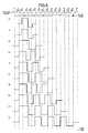
- FIG. 10 is a diagram showing a comparison of the monitored signals obtained by the first and second (conventional) recording strategies and the third recording strategy employed by the embodiment of the present invention.
- an absolute reflectivity is approximately 22%.
- the number of recording pulses is increased by one depending on the channel period 1T.
- the number of recording pulses is increased by one depending on the channel period 2T.
- the rising and falling time constants of the recording pulses respectively are 2 nsec, and in the case of the 10-times speed of the DVD, the light beam travels approximately 0.14 ⁇ m during a time which is a sum of the rising and falling time constants.
- the beam spot diameter corresponding to the light beam power of 1/e 2 is approximately 0.92 ⁇ m.
- 0.55 times the sum of the beam spot diameter and the distance traveled by the light beam can be calculated to be approximately 0.583 ⁇ m.
- the number p of recording pulses to be used for recording EFM mark lengths of 3T to 14T was set to 1 for 3T to 4T, 2 for 5T to 8T, 3 for 9T to 11T, and 4 for 14T.
- the first and second (conventional) recording strategies employed by the first and second comparison examples clearly lack the necessary level of light beam power, that is, recording power level, compared to the third recording strategy employed in the embodiment of the present invention. Therefore, it was confirmed that the third recording strategy employed in the embodiment of the present invention is very effective compared to the first and second (conventional) recording strategies employed by the first and second comparison examples.
- the performance of the phase change type optical recording medium was also measured for another fourth recording strategy which may be employed by the embodiment of the present invention, which determines the number of recording pulses for recording the recording mark lengths based on the pulse train (N 1 +N+N+).
- the number p of recording pulses was set to 1 for 3T to 5T, 2 for 6T to 8T, 3 for 9T to 11T, and 4 for 14T. Otherwise, the phase change type optical recording medium and the recording apparatus used for the measurement were the same as those described above which were used for the third recording strategy, and the jitter was evaluated under the same recording and reproducing conditions (the recording linear velocity which is the 10-times speed of the DVD) as those used to evaluate the modulation factor for the third recording strategy.
- the jitter of the same phase change type optical recording medium was similarly evaluated according to the number p of recording pulses set by the third recording strategy described above.
- the rising and falling time constants for fourth and third recording strategies were both optimized when making the evaluations, and results shown in the following Table 2 were obtained.
- the jitter (%) is obtained by dividing a time deviation (or inconsistency) of the recording mark edge by the channel period, and the smaller the jitter the smaller the mark edge shift to indicate that a satisfactory recording has been made.
- phase change type optical recording medium evaluated for the 8-times speed, 10-times speed and 12-times speed of the DVD.
- the structure of the phase change type optical recording medium was the same as that described above used to evaluate the modulation factor for the third recording strategy.
- the phase change recording layer 3 was formed by sputtering using a target material having the following compositions for making the evaluations for the 8-times speed, 10-times speed and 12-times speed.
- the recording performance of the phase change type optical recording medium was similarly evaluated according to the number p of recording pulses set by the fourth recording strategy described above.
- the number of recording pulses for 5T in the case of the 8-times speed should be set to 2
- the number of recording pulses for 5T in the case of the 8-times speed was set the same number as that in the case of the 10-times speed and the 12-times speed for the sake of convenience, and the recording was made by optimizing the recording power and the rising and falling time constants for each of the recording linear velocities.
- the recording power is proportional to (recording velocity) 1/2 , and the optimum recording power was 28 mW for the 8-times speed, 31 mW for the 10-times speed, and 34 mW for the 12-times speed.
- Table 3 shows the recording performance evaluated by the jitter. Recording Velocity Jitter (%) 8-Times Speed 8.2 10-Times Speed 7.9 12-Times Speed 8.7
- the fourth recording strategy employed by the present invention allows for a margin (or degree of freedom) in setting the number of recording pulses, and that the margin (or degree of freedom) is approximately ⁇ 10%.
- the limit of the margin (or degree of freedom) in setting the number of recording pulses may be up to approximately 0.6 times the beam spot diameter L of the light beam used for the recording from the leading edge of the recording mark, since the jitter virtually did not increase within this margin.
- phase change recording layer material 5 at.% of Ge is added to the phase change recording layer material in the case of the phase change type optical recording medium suited to operate at the 8-times speed of the DVD, so as to intentionally deteriorate the recording linear velocity response of the phase change type optical recording medium.
- the characteristics of the phase change type optical recording medium such as the recording linear velocity response and the modulation factor
- elements such as In, Mn and alloys thereof to the phase change recording layer material which is added with Ge.
- the amount of the element added to the phase change recording layer material exceeds 15 at.%, the recording linear velocity response becomes too poor, to thereby deteriorate the recording characteristics and/or cause changes in the reflectivity with lapse of time (aging).
- phase change recording layer material in the case of the phase change type optical recording medium suited to operate at the 12-times speed of the DVD, so as to improve the recording linear velocity response of the phase change type optical recording medium.
- the characteristics of the phase change type optical recording medium such as the modulation factor and the recording sensitivity
- elements such as In, Mn, Ge and alloys thereof to the phase change recording layer material.
- the amount of Sn added to the phase change recording layer material exceeds 15 at.%, the crystallization velocity becomes too fast, to thereby deteriorate the storage stability of the recording mark.
- Ge, In, Mn, Sn and alloys thereof may be added to the phase change recording layer material in the case of the phase change type optical recording medium suited to operate at the 10-times speed of the DVD, so as to finely adjust the recording characteristics of the phase change type optical recording medium.
- problems similar to those described above for the phase change type optical recording media suited to operate at the 8-times speed and the 12-times speed of the DVD will occur, if the amount of the element added to the phase change recording layer material exceeds 15 at.%,
Priority Applications (1)
| Application Number | Priority Date | Filing Date | Title |
|---|---|---|---|
| EP06018687A EP1763021A3 (de) | 2002-12-27 | 2003-12-19 | Optisches Phasenwechselaufzeichnungsmedium |
Applications Claiming Priority (2)
| Application Number | Priority Date | Filing Date | Title |
|---|---|---|---|
| JP2002380665A JP3977740B2 (ja) | 2002-12-27 | 2002-12-27 | 相変化型光記録媒体とその記録方法 |
| JP2002380665 | 2002-12-27 |
Related Child Applications (1)
| Application Number | Title | Priority Date | Filing Date |
|---|---|---|---|
| EP06018687A Division EP1763021A3 (de) | 2002-12-27 | 2003-12-19 | Optisches Phasenwechselaufzeichnungsmedium |
Publications (3)
| Publication Number | Publication Date |
|---|---|
| EP1434206A2 true EP1434206A2 (de) | 2004-06-30 |
| EP1434206A3 EP1434206A3 (de) | 2005-11-23 |
| EP1434206B1 EP1434206B1 (de) | 2008-07-23 |
Family
ID=32463643
Family Applications (2)
| Application Number | Title | Priority Date | Filing Date |
|---|---|---|---|
| EP06018687A Withdrawn EP1763021A3 (de) | 2002-12-27 | 2003-12-19 | Optisches Phasenwechselaufzeichnungsmedium |
| EP03029376A Expired - Fee Related EP1434206B1 (de) | 2002-12-27 | 2003-12-19 | Optisches Aufzeichnungsmedium vom Phasenwechseltyp und Aufzeichnungsverfahren dafür |
Family Applications Before (1)
| Application Number | Title | Priority Date | Filing Date |
|---|---|---|---|
| EP06018687A Withdrawn EP1763021A3 (de) | 2002-12-27 | 2003-12-19 | Optisches Phasenwechselaufzeichnungsmedium |
Country Status (6)
| Country | Link |
|---|---|
| US (1) | US7242657B2 (de) |
| EP (2) | EP1763021A3 (de) |
| JP (1) | JP3977740B2 (de) |
| CN (1) | CN100533557C (de) |
| DE (1) | DE60322335D1 (de) |
| TW (1) | TWI261831B (de) |
Cited By (2)
| Publication number | Priority date | Publication date | Assignee | Title |
|---|---|---|---|---|
| WO2004077419A1 (ja) | 2003-02-28 | 2004-09-10 | Pioneer Corporation | 情報記録装置及び情報記録方法 |
| EP1690692A1 (de) * | 2003-11-05 | 2006-08-16 | Ricoh Company, Ltd. | Optisches phasenwechsel-aufzeichnungsmedium |
Families Citing this family (15)
| Publication number | Priority date | Publication date | Assignee | Title |
|---|---|---|---|---|
| JP3954438B2 (ja) * | 2002-05-31 | 2007-08-08 | Tdk株式会社 | 光記録媒体への情報記録方法、情報記録装置及び光記録媒体 |
| JP4276657B2 (ja) * | 2003-04-04 | 2009-06-10 | パナソニック株式会社 | 記録媒体へのデータ記録方法、再生方法、および記録媒体 |
| JP4397751B2 (ja) | 2003-07-18 | 2010-01-13 | 三菱化学メディア株式会社 | 光記録方法及び光記録装置 |
| JP2005251265A (ja) * | 2004-03-02 | 2005-09-15 | Ricoh Co Ltd | 相変化型光記録媒体 |
| JP4136980B2 (ja) * | 2004-03-19 | 2008-08-20 | 株式会社リコー | 多層相変化型情報記録媒体及びその記録再生方法 |
| JP4382646B2 (ja) * | 2004-05-17 | 2009-12-16 | 株式会社リコー | 光記録媒体とその製造方法 |
| US20050270959A1 (en) * | 2004-06-02 | 2005-12-08 | Hiroyuki Iwasa | Recording method for optical recording medium, and optical recording apparatus |
| JP4808251B2 (ja) * | 2005-06-03 | 2011-11-02 | コーニンクレッカ フィリップス エレクトロニクス エヌ ヴィ | 光ディスクの情報層にマークを記録するための方法及び装置 |
| JP4607062B2 (ja) * | 2005-08-02 | 2011-01-05 | 株式会社リコー | 光記録媒体 |
| JP2007335044A (ja) * | 2006-06-19 | 2007-12-27 | Hitachi Ltd | 情報記録装置 |
| JP2008033981A (ja) | 2006-07-26 | 2008-02-14 | Tdk Corp | 光記録媒体の情報記録方法、光記録装置 |
| JP4303267B2 (ja) * | 2006-07-26 | 2009-07-29 | Tdk株式会社 | 光記録媒体の情報記録方法、光記録装置 |
| JP2008065258A (ja) * | 2006-09-11 | 2008-03-21 | Shin Etsu Chem Co Ltd | リソグラフィー用ペリクル |
| JP4623202B2 (ja) * | 2008-11-04 | 2011-02-02 | Tdk株式会社 | 光記録媒体の情報記録方法、光記録装置 |
| JP5828091B2 (ja) * | 2011-02-23 | 2015-12-02 | パナソニックIpマネジメント株式会社 | 光学的情報記録媒体及び光学的情報記録装置 |
Citations (10)
| Publication number | Priority date | Publication date | Assignee | Title |
|---|---|---|---|---|
| US4818666A (en) * | 1986-03-28 | 1989-04-04 | U.S. Philips Corporation | Erasable optical recording element and method of optically recording and erasing information |
| US4947372A (en) * | 1984-12-05 | 1990-08-07 | Fujitsu Limited | Optical information memory medium for recording and erasing information |
| US5732062A (en) * | 1995-10-16 | 1998-03-24 | Ricoh Company, Ltd. | Information recording apparatus, method and computer program product |
| US6256277B1 (en) * | 1997-12-09 | 2001-07-03 | Htiachi Ltd. | Information recording apparatus having controlled recording energy generation circuit |
| EP1182649A1 (de) * | 1999-05-19 | 2002-02-27 | Mitsubishi Chemical Corporation | Optisches aufzeichnungsverfahren und optisches aufzeichnungsmedium |
| EP1249834A2 (de) * | 2001-04-12 | 2002-10-16 | Ricoh Company, Ltd. | Informationsaufzeichnung mit wirksamem Pulssteuerungsschema |
| JP2003231354A (ja) * | 2002-02-05 | 2003-08-19 | Ricoh Co Ltd | 光情報記録媒体 |
| JP2003242646A (ja) * | 2002-02-15 | 2003-08-29 | Nec Corp | 情報記録媒体の記録方法及び情報記録再生装置 |
| EP1372148A2 (de) * | 2002-06-05 | 2003-12-17 | Ricoh Company, Ltd. | Optisches Aufzeichnungsmedium, Herstellungsprozess für dasselbe, Sputtertarget zur Herstellung desselben und optisches Aufzeichnungsverfahren für dasselbe |
| WO2004021341A1 (en) * | 2002-08-28 | 2004-03-11 | Koninklijke Philips Electronics N.V. | Rewritable optical data storage medium and use of such a medium |
Family Cites Families (22)
| Publication number | Priority date | Publication date | Assignee | Title |
|---|---|---|---|---|
| JP2560298B2 (ja) | 1986-12-23 | 1996-12-04 | ヤマハ株式会社 | 光デイスク記録装置 |
| US5875160A (en) * | 1996-12-14 | 1999-02-23 | Ricoh Company, Ltd. | Method and device for initializing optical recording medium of phase change type, and optical recording medium |
| US6096398A (en) * | 1997-11-28 | 2000-08-01 | Ricoh Company, Ltd. | Phase-change optical recording medium |
| US6177167B1 (en) * | 1997-12-02 | 2001-01-23 | Ricoh Company, Ltd. | Optical information recording medium |
| US6426936B1 (en) * | 1998-01-27 | 2002-07-30 | Ricoh Company, Ltd. | Phase-change medium usable in phase-difference tracking |
| JP2001209981A (ja) * | 1999-02-09 | 2001-08-03 | Ricoh Co Ltd | 光ディスク基板成膜装置、光ディスク基板成膜方法、基板ホルダーの製造方法、基板ホルダー、光ディスクおよび相変化記録型光ディスク |
| JP2000322740A (ja) * | 1999-05-12 | 2000-11-24 | Ricoh Co Ltd | 光記録媒体及びその記録方法 |
| US6479121B1 (en) * | 1999-09-21 | 2002-11-12 | Ricoh Company, Ltd. | Optical recording medium and method of fabricating same |
| JP4112153B2 (ja) * | 2000-03-31 | 2008-07-02 | 株式会社リコー | 光記録媒体の検査方法 |
| US6987720B2 (en) * | 2000-07-13 | 2006-01-17 | Ricoh Company, Ltd. | Information recording and/or reproducing apparatus, information recording and/or reproducing method, and phase-change recording medium for use in the apparatus and the methods |
| JP2003034081A (ja) * | 2000-09-14 | 2003-02-04 | Ricoh Co Ltd | 相変化型光情報記録媒体 |
| JP2002096560A (ja) | 2000-09-22 | 2002-04-02 | Ricoh Co Ltd | 光記録媒体 |
| DE60125675T2 (de) * | 2000-09-28 | 2007-10-11 | Ricoh Company, Ltd. | Optisches Aufzeichnungsmedium, Verfahren zu dessen Herstellung und Verfahren und Vorrichtung zum Aufzeichnen auf oder Lesen von diesem Medium |
| US20020160306A1 (en) * | 2001-01-31 | 2002-10-31 | Katsunari Hanaoka | Optical information recording medium and method |
| JP2002237096A (ja) * | 2001-02-09 | 2002-08-23 | Ricoh Co Ltd | 光記録媒体 |
| US6846611B2 (en) * | 2001-02-28 | 2005-01-25 | Ricoh Company, Ltd. | Phase-change optical recording medium |
| US6914866B2 (en) * | 2001-04-06 | 2005-07-05 | Ricoh Company, Ltd. | Optical information recording medium and information recording method and apparatus using the recording medium |
| CA2416149A1 (en) | 2001-04-12 | 2002-10-24 | Koninklijke Philips Electronics N.V. | Rewritable optical data storage medium and use of such a medium |
| JP2003305955A (ja) * | 2001-05-21 | 2003-10-28 | Ricoh Co Ltd | 光記録媒体及び記録方法 |
| JP3860001B2 (ja) | 2001-09-10 | 2006-12-20 | Tdk株式会社 | 光記録媒体への情報記録方法、情報記録装置及び光記録媒体 |
| JP2003228834A (ja) * | 2002-01-30 | 2003-08-15 | Ricoh Co Ltd | 情報記録方式及び光記録媒体 |
| US7260053B2 (en) * | 2002-04-02 | 2007-08-21 | Ricoh Company, Ltd. | Optical recording medium, process for manufacturing the same, sputtering target for manufacturing the same, and optical recording process using the same |
-
2002
- 2002-12-27 JP JP2002380665A patent/JP3977740B2/ja not_active Expired - Fee Related
-
2003
- 2003-12-09 US US10/730,026 patent/US7242657B2/en not_active Expired - Fee Related
- 2003-12-11 TW TW092135053A patent/TWI261831B/zh not_active IP Right Cessation
- 2003-12-19 EP EP06018687A patent/EP1763021A3/de not_active Withdrawn
- 2003-12-19 EP EP03029376A patent/EP1434206B1/de not_active Expired - Fee Related
- 2003-12-19 DE DE60322335T patent/DE60322335D1/de not_active Expired - Lifetime
- 2003-12-27 CN CNB2003101251992A patent/CN100533557C/zh not_active Expired - Fee Related
Patent Citations (10)
| Publication number | Priority date | Publication date | Assignee | Title |
|---|---|---|---|---|
| US4947372A (en) * | 1984-12-05 | 1990-08-07 | Fujitsu Limited | Optical information memory medium for recording and erasing information |
| US4818666A (en) * | 1986-03-28 | 1989-04-04 | U.S. Philips Corporation | Erasable optical recording element and method of optically recording and erasing information |
| US5732062A (en) * | 1995-10-16 | 1998-03-24 | Ricoh Company, Ltd. | Information recording apparatus, method and computer program product |
| US6256277B1 (en) * | 1997-12-09 | 2001-07-03 | Htiachi Ltd. | Information recording apparatus having controlled recording energy generation circuit |
| EP1182649A1 (de) * | 1999-05-19 | 2002-02-27 | Mitsubishi Chemical Corporation | Optisches aufzeichnungsverfahren und optisches aufzeichnungsmedium |
| EP1249834A2 (de) * | 2001-04-12 | 2002-10-16 | Ricoh Company, Ltd. | Informationsaufzeichnung mit wirksamem Pulssteuerungsschema |
| JP2003231354A (ja) * | 2002-02-05 | 2003-08-19 | Ricoh Co Ltd | 光情報記録媒体 |
| JP2003242646A (ja) * | 2002-02-15 | 2003-08-29 | Nec Corp | 情報記録媒体の記録方法及び情報記録再生装置 |
| EP1372148A2 (de) * | 2002-06-05 | 2003-12-17 | Ricoh Company, Ltd. | Optisches Aufzeichnungsmedium, Herstellungsprozess für dasselbe, Sputtertarget zur Herstellung desselben und optisches Aufzeichnungsverfahren für dasselbe |
| WO2004021341A1 (en) * | 2002-08-28 | 2004-03-11 | Koninklijke Philips Electronics N.V. | Rewritable optical data storage medium and use of such a medium |
Non-Patent Citations (2)
| Title |
|---|
| PATENT ABSTRACTS OF JAPAN vol. 2003, no. 12, 5 December 2003 (2003-12-05) -& JP 2003 231354 A (RICOH CO LTD), 19 August 2003 (2003-08-19) * |
| PATENT ABSTRACTS OF JAPAN vol. 2003, no. 12, 5 December 2003 (2003-12-05) -& JP 2003 242646 A (NEC CORP), 29 August 2003 (2003-08-29) * |
Cited By (6)
| Publication number | Priority date | Publication date | Assignee | Title |
|---|---|---|---|---|
| WO2004077419A1 (ja) | 2003-02-28 | 2004-09-10 | Pioneer Corporation | 情報記録装置及び情報記録方法 |
| EP1598816A1 (de) * | 2003-02-28 | 2005-11-23 | Pioneer Corporation | Informationsaufzeichnungseinrichtung und informationsaufzeichnungsverfahren |
| EP1598816A4 (de) * | 2003-02-28 | 2008-12-31 | Pioneer Corp | Informationsaufzeichnungseinrichtung und informationsaufzeichnungsverfahren |
| US7586823B2 (en) | 2003-02-28 | 2009-09-08 | Pioneer Corporation | Information recording apparatus and information recording method |
| EP1690692A1 (de) * | 2003-11-05 | 2006-08-16 | Ricoh Company, Ltd. | Optisches phasenwechsel-aufzeichnungsmedium |
| EP1690692A4 (de) * | 2003-11-05 | 2008-11-26 | Ricoh Kk | Optisches phasenwechsel-aufzeichnungsmedium |
Also Published As
| Publication number | Publication date |
|---|---|
| CN1534620A (zh) | 2004-10-06 |
| EP1434206B1 (de) | 2008-07-23 |
| JP3977740B2 (ja) | 2007-09-19 |
| US7242657B2 (en) | 2007-07-10 |
| TWI261831B (en) | 2006-09-11 |
| DE60322335D1 (de) | 2008-09-04 |
| JP2004213743A (ja) | 2004-07-29 |
| EP1763021A3 (de) | 2007-05-02 |
| US20040136307A1 (en) | 2004-07-15 |
| EP1434206A3 (de) | 2005-11-23 |
| CN100533557C (zh) | 2009-08-26 |
| EP1763021A2 (de) | 2007-03-14 |
| TW200421334A (en) | 2004-10-16 |
Similar Documents
| Publication | Publication Date | Title |
|---|---|---|
| US7242657B2 (en) | Phase change type optical recording medium and recording method therefor | |
| US7102977B2 (en) | Phase-change optical recording medium and recording method and apparatus for the same | |
| US7277376B2 (en) | Optical recording method | |
| US7336580B2 (en) | Optical recording method, optical recorder, and optical recording medium | |
| US20070081445A1 (en) | Optical recording medium, multi-layered optical recording medium, and optical recording method and recording apparatus using the same | |
| KR100912450B1 (ko) | 광 기록 매체 및 광 기록 방법 | |
| US7471606B2 (en) | Method of recording information on optical recording medium, and information recording and reproducing apparatus | |
| EP1484751B1 (de) | Verfahren zum aufzeichnen von informationen auf einem optischen aufzeichnungsmedium, informationsaufzeichnungsgerät und optisches aufzeichnungsmedium | |
| JPH11110822A (ja) | 光記録媒体およびその記録再生方法 | |
| JP3882532B2 (ja) | 光学的情報記録用媒体及び記録消去方法 | |
| WO2002043060A1 (fr) | Moyen d'enregistrement optique | |
| US20050089798A1 (en) | Method for recording information on optical recording medium, information recorder, and optical recording medium | |
| US7943223B2 (en) | Optical recording medium and recording film material | |
| JP4070497B2 (ja) | 光記録媒体、その記録方法及び記録装置 | |
| JP3870702B2 (ja) | 光学的情報記録用媒体及びその記録消去方法 | |
| US7715293B2 (en) | Optical recording medium and method of recording to the same | |
| JP4013311B2 (ja) | 光学的情報の記録媒体と記録方法 | |
| JP3903811B2 (ja) | 光学的情報記録用媒体及び記録消去方法 | |
| JPWO2006001131A1 (ja) | 光学的情報記録媒体および光学的情報記録再生システム | |
| JP4410081B2 (ja) | 光記録方法 | |
| JP3881215B2 (ja) | 光情報記録方法 | |
| JPWO2003079336A1 (ja) | 記録装置及び記録方法 | |
| WO2005038788A1 (ja) | 光記録方法 | |
| JP2004022007A (ja) | 光記録方法及び光情報記録媒体 | |
| JP2007257809A (ja) | 光記録媒体及び光記録方法 |
Legal Events
| Date | Code | Title | Description |
|---|---|---|---|
| PUAI | Public reference made under article 153(3) epc to a published international application that has entered the european phase |
Free format text: ORIGINAL CODE: 0009012 |
|
| AK | Designated contracting states |
Kind code of ref document: A2 Designated state(s): AT BE BG CH CY CZ DE DK EE ES FI FR GB GR HU IE IT LI LU MC NL PT RO SE SI SK TR |
|
| AX | Request for extension of the european patent |
Extension state: AL LT LV MK |
|
| PUAL | Search report despatched |
Free format text: ORIGINAL CODE: 0009013 |
|
| AK | Designated contracting states |
Kind code of ref document: A3 Designated state(s): AT BE BG CH CY CZ DE DK EE ES FI FR GB GR HU IE IT LI LU MC NL PT RO SE SI SK TR |
|
| AX | Request for extension of the european patent |
Extension state: AL LT LV MK |
|
| 17P | Request for examination filed |
Effective date: 20051206 |
|
| AKX | Designation fees paid |
Designated state(s): DE ES FR GB IT NL |
|
| GRAJ | Information related to disapproval of communication of intention to grant by the applicant or resumption of examination proceedings by the epo deleted |
Free format text: ORIGINAL CODE: EPIDOSDIGR1 |
|
| GRAP | Despatch of communication of intention to grant a patent |
Free format text: ORIGINAL CODE: EPIDOSNIGR1 |
|
| GRAS | Grant fee paid |
Free format text: ORIGINAL CODE: EPIDOSNIGR3 |
|
| GRAA | (expected) grant |
Free format text: ORIGINAL CODE: 0009210 |
|
| AK | Designated contracting states |
Kind code of ref document: B1 Designated state(s): DE ES FR GB IT NL |
|
| REG | Reference to a national code |
Ref country code: GB Ref legal event code: FG4D |
|
| REF | Corresponds to: |
Ref document number: 60322335 Country of ref document: DE Date of ref document: 20080904 Kind code of ref document: P |
|
| NLV1 | Nl: lapsed or annulled due to failure to fulfill the requirements of art. 29p and 29m of the patents act | ||
| PG25 | Lapsed in a contracting state [announced via postgrant information from national office to epo] |
Ref country code: ES Free format text: LAPSE BECAUSE OF FAILURE TO SUBMIT A TRANSLATION OF THE DESCRIPTION OR TO PAY THE FEE WITHIN THE PRESCRIBED TIME-LIMIT Effective date: 20081103 Ref country code: NL Free format text: LAPSE BECAUSE OF FAILURE TO SUBMIT A TRANSLATION OF THE DESCRIPTION OR TO PAY THE FEE WITHIN THE PRESCRIBED TIME-LIMIT Effective date: 20080723 |
|
| PLBE | No opposition filed within time limit |
Free format text: ORIGINAL CODE: 0009261 |
|
| STAA | Information on the status of an ep patent application or granted ep patent |
Free format text: STATUS: NO OPPOSITION FILED WITHIN TIME LIMIT |
|
| 26N | No opposition filed |
Effective date: 20090424 |
|
| PG25 | Lapsed in a contracting state [announced via postgrant information from national office to epo] |
Ref country code: IT Free format text: LAPSE BECAUSE OF FAILURE TO SUBMIT A TRANSLATION OF THE DESCRIPTION OR TO PAY THE FEE WITHIN THE PRESCRIBED TIME-LIMIT Effective date: 20080723 |
|
| PGFP | Annual fee paid to national office [announced via postgrant information from national office to epo] |
Ref country code: FR Payment date: 20091221 Year of fee payment: 7 Ref country code: GB Payment date: 20091216 Year of fee payment: 7 |
|
| PGFP | Annual fee paid to national office [announced via postgrant information from national office to epo] |
Ref country code: DE Payment date: 20091217 Year of fee payment: 7 |
|
| GBPC | Gb: european patent ceased through non-payment of renewal fee |
Effective date: 20101219 |
|
| REG | Reference to a national code |
Ref country code: FR Ref legal event code: ST Effective date: 20110831 |
|
| PG25 | Lapsed in a contracting state [announced via postgrant information from national office to epo] |
Ref country code: FR Free format text: LAPSE BECAUSE OF NON-PAYMENT OF DUE FEES Effective date: 20110103 |
|
| REG | Reference to a national code |
Ref country code: DE Ref legal event code: R119 Ref document number: 60322335 Country of ref document: DE Effective date: 20110701 |
|
| PG25 | Lapsed in a contracting state [announced via postgrant information from national office to epo] |
Ref country code: DE Free format text: LAPSE BECAUSE OF NON-PAYMENT OF DUE FEES Effective date: 20110701 Ref country code: GB Free format text: LAPSE BECAUSE OF NON-PAYMENT OF DUE FEES Effective date: 20101219 |