EP1249834A2 - Informationsaufzeichnung mit wirksamem Pulssteuerungsschema - Google Patents
Informationsaufzeichnung mit wirksamem Pulssteuerungsschema Download PDFInfo
- Publication number
- EP1249834A2 EP1249834A2 EP20020252572 EP02252572A EP1249834A2 EP 1249834 A2 EP1249834 A2 EP 1249834A2 EP 20020252572 EP20020252572 EP 20020252572 EP 02252572 A EP02252572 A EP 02252572A EP 1249834 A2 EP1249834 A2 EP 1249834A2
- Authority
- EP
- European Patent Office
- Prior art keywords
- pulse
- heating
- recording
- cooling
- recording medium
- Prior art date
- Legal status (The legal status is an assumption and is not a legal conclusion. Google has not performed a legal analysis and makes no representation as to the accuracy of the status listed.)
- Granted
Links
Images


Classifications
-
- G—PHYSICS
- G11—INFORMATION STORAGE
- G11B—INFORMATION STORAGE BASED ON RELATIVE MOVEMENT BETWEEN RECORD CARRIER AND TRANSDUCER
- G11B7/00—Recording or reproducing by optical means, e.g. recording using a thermal beam of optical radiation by modifying optical properties or the physical structure, reproducing using an optical beam at lower power by sensing optical properties; Record carriers therefor
- G11B7/004—Recording, reproducing or erasing methods; Read, write or erase circuits therefor
- G11B7/0045—Recording
- G11B7/00456—Recording strategies, e.g. pulse sequences
-
- G—PHYSICS
- G11—INFORMATION STORAGE
- G11B—INFORMATION STORAGE BASED ON RELATIVE MOVEMENT BETWEEN RECORD CARRIER AND TRANSDUCER
- G11B7/00—Recording or reproducing by optical means, e.g. recording using a thermal beam of optical radiation by modifying optical properties or the physical structure, reproducing using an optical beam at lower power by sensing optical properties; Record carriers therefor
- G11B7/004—Recording, reproducing or erasing methods; Read, write or erase circuits therefor
- G11B7/006—Overwriting
- G11B7/0062—Overwriting strategies, e.g. recording pulse sequences with erasing level used for phase-change media
-
- G—PHYSICS
- G11—INFORMATION STORAGE
- G11B—INFORMATION STORAGE BASED ON RELATIVE MOVEMENT BETWEEN RECORD CARRIER AND TRANSDUCER
- G11B7/00—Recording or reproducing by optical means, e.g. recording using a thermal beam of optical radiation by modifying optical properties or the physical structure, reproducing using an optical beam at lower power by sensing optical properties; Record carriers therefor
- G11B7/12—Heads, e.g. forming of the optical beam spot or modulation of the optical beam
- G11B7/125—Optical beam sources therefor, e.g. laser control circuitry specially adapted for optical storage devices; Modulators, e.g. means for controlling the size or intensity of optical spots or optical traces
- G11B7/126—Circuits, methods or arrangements for laser control or stabilisation
Definitions
- the present invention relates to an information recording method and an information recording device suitable for recording an optical mark on an optical disk, especially a phase-change optical disk using a heat applied by laser light irradiation.
- a method of recording information in which a hole is formed in a recording film by a thermal effect of optical energy of irradiated laser light, changing a crystal structure, or changing direction of magnetization, or deforming the recording film, or the like, and, thus, an optical mark is recorded on a recording medium.
- Such a method is applied to an optical disk device or a magneto-optical disk device in recent years, and is put in practical use.
- increase in recording density and increase in memory capacity are demanded, as an external information recording device for an information processing device, such as a computer.
- an information recording device disclosed in Japanese laid-open patent application No. 8-221757 (see Japanese patent No. 2899551) is known.
- a rate of heating/cooling of a phase-change recording medium is controlled by irradiating laser light in a form of an optical pulse for heating and an optical pulse for cooling alternately, and thereby, amorphous mark formation is made by sudden cooling while crystal formation is made by gradual cooling.
- Such a method may also be applied to information recording on CD-RW.
- a recording length of the optical mark is controlled by changing a manner of repetition of the cooling pulses and heating pulses with bit period intervals.
- the predetermined bit period T becomes much shorter and becomes much higher bit rate of 10 nanoseconds or less, it becomes difficult to make a laser pulse to be emitted properly.
- the limit thereof is approximately 12 times the standard rate on CD.
- heating/cooling pulse may have a length of approximately 1.25T, or the like, and, thereby, it may not be possible to precisely emit light-emitting pulse at a time of some high-speed recording case.
- Media only for reproduction such as a CD for music, a CD-ROM, a DVD, and a DVD-R, an OM, and so forth are put in practical use with development in multimedia.
- a phase-change disk also attracts attention besides write-once optical disk employing coloring material, and rewritable MO disk using an optical magnetism material.
- phase-change disk a recording material is switched reversibly between a crystal phase and an amorphous phase, and, thus, information is recorded there. Furthermore, in the phase-change disk, reproduction is made only with laser light from a light source of a semiconductor laser and no external magnetic field is needed, unlike MO media, etc. Further, informational recording and erasing can be performed at once by laser light in the phase-change medium.
- the semiconductor laser is driven by a semiconductor laser driving circuit here.
- a semiconductor laser light-emitting waveform of single pulse generated as a recording waveform for recording information on an information recording medium based on EFM (Eight Fourteen Modulation) code, etc. is used.
- EFM Eight Fourteen Modulation
- a record mark has a distortion in shape like a tear drop with an accumulated heat, or insufficient cooling speed, forming of an amorphous phase becomes inadequate, and there may cause problems that the thus-formed record mark has not a sufficient reflectance to laser light.
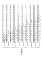
- forming of a mark on phase-change media is made by laser light of multi-pulse waveform, as shown in FIG. 1A, which includes recording power in many stages generated based on the EFM code, etc.
- a top heating pulse Htop on a mark part of this multi-pulse waveform fully carries out preliminary heating of the recording film of the phase-change medium more than a melting-point temperature. Then, following the top heating pulse Htop, a plurality of heating pulses Hmp occur, while cooling multi-pulses Cmp also occur between these heating pulses, respectively, as shown in the figure.
- An erasing part of this multi-pulse waveform includes an erasing pulse E, and a light-emitting power Pe thereof is set such as Phmp ⁇ Pe ⁇ Pcmp
- an amorphous phase is formed as a mark part by a condition of sudden cooling of heating ⁇ cooling.
- a crystal phase is formed by a condition of gentle cooling of only heating on the erase portion E.
- a mark position (PPM) type i.e., a mark position (PM) type and a mark edge (PWM) type.
- PPM mark position
- PWM mark edge
- the mark edge type which can respond to high-density recording is used.
- a heating/cooling pulse having a length of 0.5T with respect to a recording channel clock period T is used.
- FIG. 1A shows a typical example of recording waveform. Since this recording waveform can always record the record data of different mark length on a predetermined fixed heating/cooling condition, edge shift occurring depending on the mark length of record data can be effectively reduced. Moreover, in a case where high-speed recording is performed by this recording waveform, the recording channel clock frequency is made twice and 4 times, the same rate at which the record line speed is increased. In this case, the basic number of pulses and the relation between levels of the recording power are maintained, and, the pulse width of the heating multi-pulses Hmp can be set variably in a range between 0.25T and 0.55T.
- phase-change media When recording information on phase-change media by the mark edge recording type is performed, it is important for phase-change media to perform heating sufficient and sudden cooling in a record mark formation portion so as to form edge parts front and rear of the mark clearly.
- the recording channel clock frequency is made twice or 4 times, and, thereby, the heating pulse and cooling pulse have a reduced time interval each such that sufficient temperature increase and decrease required for phase change in the recording film may not be achieved.
- the rate of the interval of the heating pulse with respect to the recording channel clock pulse T thus increases, and, thereby, a sufficient cooling time could not be secured, thus forming of a mark becomes inadequate, and recording of exact mark length may become impossible.
- the pulse width of a rear heating pulse and a rear cooling pulse has a time interval approximately same as the recording channel clock period.
- the substantial period of the multi-pulse sequence is set one half of the recording channel clock pulses, and, thus, it is possible to secure sufficient heating time and cooling time.
- the predetermined heating pulse width of the multi-pulse sequence is individually changed according to each mark data length, and, thus, control processing of pulse width should become complicated.
- Japanese laid-open patent application No. 11-175976 discloses a method of driving an energy generating means so as to appropriately change the number of applying energy pulses within a mark formation interval according to a mark length so that an interval between arbitrary change points of the applied energy per unit time may become more than a detection window width or an approximately natural number of times the detection window width at a time of information recording.
- This method is similar to that of Japanese laid-open patent application No. 9-134525, and, according thereto, the pulse width and the heating power level of the head heating pulse or the last heating pulse of a multi-pulse sequence is changed appropriately so that the energy for mark formation is controlled.
- a setup of pulse width of a multi-pulse sequence in high-speed recording is such that ratio of a heating pulse width Thmp with respect to the recording channel clock period T becomes larger, and, thereby, a mark part formed according to a sudden cooling requirement on cooling pulse becomes thinner. This phenomenon becomes remarkable as the ratio of heating pulse exceeds 0.55T, and, thus, this is a critical speed of high-speed recording.
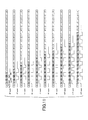
- FIG. 5A illustrates recording waveforms in which, whenever a mark length of record data increases 1T, light of multi-pulses adding 1 set of heating pulse and cooling pulse is used. Since the recording waveform enables recording of record data of different mark length on a fixed heating/cooling condition, edge shift occurring depending on the mark length of record data is avoided. Moreover, in case where high-speed recording is performed by this recording waveform, the recording channel clock frequency is made twice ( ⁇ 2), 3 times ( ⁇ 3), or 4 times ( ⁇ 4) same as the multiplication of the recording line speed, while the pulse width Thmp of heating multi-pulses Hmp is changed accordingly in a range between approximately 0.25T and 0.55T.
- phase-change media When recording information on phase-change media by the above-mentioned mark edge recording type is applied, it is important for the phase-change media to be heated sufficiently and cooled suddenly in a record mark formation portion so as to form the edge parts before and after the mark clearly, as mentioned above.
- a sufficient heating energy can be applied even when the ratio of the heating pulse interval with respect to the period T of the recording channel clock signal is 0.20T or less. Accordingly, as shown in FIG. 5A, the heating pulse width is fixed as the recording frequency is lowered. Thereby, however, the cooling pulse width becomes more than 0.8T, which is too long to perform accurate mark formation. In other words, as the cooling pulse width becomes too long, proper cooling requirement cannot be satisfied, and, thus, a resulting record mark becomes thinner, as shown in FIG. 5A. Accordingly, a reproduction signal, i.e., an RF signal obtained from such a thin mark has amplitude vibration occurring therein, and, thereby, a substantial mark length becomes too short, as the recording data length becomes longer in this condition.
- each pulse width of the heating multi-pulses is made not to be reduced from the order of 0.25T so as to keep a fixed duty ratio, and, thereby, it becomes necessary to control heating power so as to keep a proper heating energy.
- the heating energy defined by the heating pulse width becomes excessive in case of low-speed recording, and, thereby, degradation of recording film of the medium may occur.
- the pulse width of the last cooling pulse is made to have a short interval or a long interval selectively for two mark data lengths in which the number of heating pulses and the number of cooling pulses becomes identical.
- the ratio of each erase power of the erase pulse positioned immediately behind the last cooling pulse should be made different.
- an information recording method for recording at higher speed is realized with a simple and low-cost additional circuit.
- the present invention it is possible to secure sufficient heating time and cooling time, and, also, obtain a predetermined record mark length by simple change of configuration of multi-pulse sequence, through simple pulse control. Furthermore, it is possible to provide information recording scheme which enables information recording at a lower speed in comparison to the recording speed range on the conventional information recording media.
- the number of multi-pulses which suits the information recording medium is increased, and thus it is enabled to form a proper mark, without changing each heating pulse of multi-pulse sequence irregularly.
- the number of heating pulse and cooling pulse is made increase by two sets thereof whenever the mark data length increases 1T in case low-speed recording than the predetermined range, and also, the heating pulse width would be otherwise set much smaller than a predetermined pulse width.
- the recording requirement on the low speed recording can be set easily in a recording device.
- an information recording method for recording at lower speed is realized with a simple and low-cost additional circuit.
- heating/cooling pulses are made to have pulse widths longer with respect to the period of recording channel clock signal in case of high-speed recording. Therefore, even when response of laser source drive device is not superior enough, substantially high-speed recording can be achieved with a simple configuration at low cost. Furthermore, by widening the pulse widths of the recording pulses of laser beam, it is possible to avoid thermal interference between adjacent record marks.
- the pulse widths of heating/cooling pulses are narrower than those of the top pulses.
- the pulses other than top ones are narrowed so that record unevenness in the intermediate part of the record mark can be avoided, while the top pulses which cannot receive residual heat of preceding heating pulse are widened.
- the ratio of heating pulse width should be adjusted appropriately so that heating power should not be made much higher while sufficient cooling speed can be secured.
- the period of heating/cooling pulses should be widened with respect to the recording channel clock period.
- FIGS. 6, 7 and 8 A first embodiment of the present invention will now be described with reference to FIGS. 6, 7 and 8.
- An information recording device 1 in the first embodiment is applied to a personal computer with a CD-RW drive built therein, for example.
- this information recording device 1 has an information processing device 2 which includes a main part of a personal computer, as shown in FIG. 6, a keyboard 3, an information input part 4, a disk drive mechanism (CD-RW drive) 5, and a laser drive circuit 6 which are connected to this information processing device 2, and a laser light source 7 which is connected to the laser drive circuit 6.
- an information processing device 2 which includes a main part of a personal computer, as shown in FIG. 6, a keyboard 3, an information input part 4, a disk drive mechanism (CD-RW drive) 5, and a laser drive circuit 6 which are connected to this information processing device 2, and a laser light source 7 which is connected to the laser drive circuit 6.
- CD-RW drive disk drive mechanism
- the information processing device 2 controls the disk drive mechanism 5 and the laser drive circuit 6 according to this time-series information, when this information is input into the information input part 4 from the outside.
- This laser drive circuit 6 follows this control, and drives the laser light source 7 so as to perform modulation control of light-emission power of laser light of the laser light source 7 made of a semiconductor laser.
- a laser light source control unit to perform the control which will be described later is formed of this laser drive circuit 6 and information processing device 2.
- the disk drive mechanism 5 drives so as to rotate an optical disk (optical information. recording medium) in phase-change type and the laser light of the laser light source 7 is applied thereonto.
- code data of a CD-ROM format is overwritten to the optical disk 8 of phase-change recording medium according to the above-mentioned mark edge recording scheme using EFM code.
- the laser light of multi-pulses emitted by the laser light source 7 at a time of recording takes either a state of heating/cooling pulses for mark recording which include heating pulses of high power level Pw, and cooling pulses of low power Pc, or a state of erase pulses for the purpose of un-marking (with no change) not forming mark or erasing (conversion into un-mark) marks of an intermediate power Pe.
- the scheme of driving the laser light source 7 at these three power levels is well-known from the above-mentioned two Japanese patent publications, and so forth.
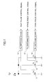
- the laser drive circuit 6 is configured as shown in FIG. 7. Namely, a constant current source 11 which provides a driving current for making light emit at the power level Pw to the laser light source 7, a constant current source 12 which provides the driving current for making light emit at the power level Pe, and a constant current source 13 which provides a driving current for making light emit at the power level Pc are connected in parallel, and also, switching devices 14, 15, and 16 which carry out switching control to selectively provide the driving current to each of the constant current sources 11, 12, and 13 based on the pulse control signal from information processing device 2 are connected.
- FIG. 8 shows an example of input data bit sequence at a predetermined bit period T, and shows a state of two values by existence/absence of halftone in the figure (halftone part denotes the value "1" while and non-halftone part denotes the value "0").
- halftone part denotes the value "1”
- non-halftone part denotes the value "0”
- a data placement rule should be applied such that bits of a same value continues 2T, 3T or more periods.
- light-emission operation is made such that the heating/cooling pulse period tw + tc is set to be within the range between 1.5T and 3T while the ratio of the heating pulse width with respect to the period tw/(tw + tc) is set to be within the range between 0.2 and 0.8.
- the heating/cooling pulses includes a heating pulse occurring for tw and cooling pulse occurring for tc, and, by controlling the ratio of tw/(tw + tc), the balance between heating time and cooling time can be adjusted and thereby, it can be optimized according to the sensitivity, response, or the like of the recording medium, and also, the emitable power and/or response of the recording device.
- the desirable range is 0.2 ⁇ tw/(tw + tc) ⁇ 0.8, and, when it is optimized into approximately 0.5, heating and cooling can be balanced, recording power can also be saved, a demand to the response at the time of recording power modulation can also be eased, and as a result, practically desirable practical conditions are obtained.
- the above-mentioned requirement of the period of tw + tc within the range between 1.5T and 3T should not be necessarily satisfied.
- the above-mentioned range may be between 1.5T and 2T. That is, 1.5T ⁇ tw + tc ⁇ 2T
- the top heating/cooling pulses which cannot easily receive influence of remaining heat from the preceding heating pulse thus needs a larger energy. Accordingly, energy shortage on the top pulses should be avoided so that the requirement that 1.5T ⁇ tw + tc ⁇ 3T.
- the subsequent pulses by controlling the requirement such that the period of tw + tc between 1.5T and 2T, unevenness of recording in the middle portion of a long mark can be lessened effectively.
- phase-change medium applied as the optical disk application of erase power Pe having the power level between the heating power Pw and cooling power Pc is applied continuously during an interval in which no mark is formed.
- erase power Pe having the power level between the heating power Pw and cooling power Pc is applied continuously during an interval in which no mark is formed.
- FIG. 9 A second embodiment of the present invention will now be described with reference to FIG. 9.
- the same portion as the portion shown on the first embodiment is shown using the same reference numeral, and description thereof is omitted (similarly on the subsequent third and fourth embodiments).
- the period of heating/cooling pulses tw + tc is set any one of 1.5T, 1.75T, and 2T.
- each mark can be formed by a very regular combination.
- the sum total length of combined pairs of heating and cooling pulses may be set to be within a range between (nT - 1.5T) and (nT + 0.5T) for a record mark of nT, where 'n' denotes an integer more than 2.
- the length of record mark does not shift from a predetermined length by a limited range of the sum total length of the combined pairs of heating and cooling pulses.
- distortion between record marks can also be corrected by selecting a combination of recording pulses.
- a record mark since a record mark is recorded in many cases somewhat longer than the total length (widths) of recording pulses, it can be correctly adjusted to the predetermined length actually recorded as a result of adjustment being made within the range according to the present embodiment.
- FIG. 10 An example made in agreement between the length of the mark which should be recorded and the sum total length of the heating and cooling pulse pairs combined in each of all length types is shown in FIG. 10. Especially, the example shown in the figure corresponds to the example according to the second embodiment, and, it can be seen that the length of record mark can be set up correctly according to the second embodiment.
- the following setting is made: Mark length tw + tc tw/(tw + tc) 3T 1.5T, 1.5T 0.5, 0.5 4T 2T, 2T 0.5, 0.5 5T 1.5T, 1.5T, 2T 0.5, 0.5, 0.5 6T 2T, 2T, 2T 0.5, 0.5, 0.5 7T 1.5T, 1.5T, 2T, 2T 0.5, 0.5, 0.5, 0.5, 0.5 8T 2T, 2T, 2T, 2T 0.5, 0.5. 0.5, 0.5 9T 1.5, 1.5, 2T, 2T, 2T 0.5, 0.5.
- a fourth embodiment of the present invention will now be described with reference to FIGS. 11 and 12. According to the present embodiment, regardless of the specified length of each record mark, respective setting values on the top heating/cooling pulses and last heating/cooling pulses are fixed.
- FIG. 11 shows an example where, for the top part and the last part of each mark length, the heating/cooling pulses of period 2T are disposed except the mark lengths of 3T and 5T.
- Fit. 12 shows another example where the top part is placed with the heating/cooling pulses of period 2T, and the last part is placed with the heating/cooling pulses of period 1.5T, except for some exceptions.
- the top heating/cooling pulses and last heating/cooling pulses of 3T mark, the top heating/cooling pulses of 6T mark and the top heating/cooling pulses of 9T mark are set in a manner different from usual setup.
- the fourth embodiment even in a case where the positions of mark end parts would be otherwise deviated (mark end shift) due to difference in property of particular recording media, by appropriately adjusting the respective setting values on the top and last end parts of the sequence of combination of heating/cooling pulse pairs according to the property of relevant recording medium, it is possible to cope with variation between different recording media, and, thus, to perform satisfactory recording even on different recording media.
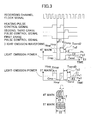
- FIG. 14 shows an example of a configuration of an information recording/reproducing device according to the fifth embodiment of the present invention.
- This device records (overwrites) code data of CD-ROM format on a phase-change optical disk 101 which is an information recording medium, and performs mark edge (PWM) recording using EFM or EFM plus code (generally called EFM family code).
- PWM mark edge
- This information recording/reproducing device generates a pulse control signal based on a recording channel clock signal and EFM data at a time of recording.
- a semiconductor laser drive circuit (LD driver part) 102 drives a semiconductor laser (LD) 104 of an optical head 103 with a driving current according to the pulse control signal, and thus, causes the light source to emit a light-emission waveform of multi-pulse sequence, as shown in FIG. 1B.
- LD driver part drives a semiconductor laser (LD) 104 of an optical head 103 with a driving current according to the pulse control signal, and thus, causes the light source to emit a light-emission waveform of multi-pulse sequence, as shown in FIG. 1B.
- phase-change optical disk 101 driven and rotted by a spindle motor 105, while light of the light-emission waveform of multi-pulse sequence from the semiconductor laser LD 104 is applied to the phase-change recording layer of the phase-change optical disk 101 through an optical system (not shown) with the optical head 103, and thus, record marks are formed onto the phase-change optical disk 101.
- this information recording/reproducing device drives the semiconductor laser LD 104 by the LD driver part 102, which is thus made to emit light at reproduction power (read power), the light of the reproduction power from the semiconductor laser LD 104 is applied through the optical system onto the phase-change optical disk 101 with the optical head 103.
- a reproduction signal is obtained through reception of reflected light with a photoelectric device (not shown) through the optical system, and through photoelectric conversion.
- the light of the light-emission waveform of multi-pulse sequence emitted by the semiconductor laser LD 104 at a time of recording includes a top heating pulse Htop followed by a plurality of heating pulses Hmp, and a plurality of cooling pulses Cmp occurring therebetween, respectively, as shown in FIG. 1B.
- the light-emission power Phtop of the top heating pulse Htop and the light-emission power Phmp of the following heating pulse Hmp are the same.
- a constant current corresponding to a light-emission power Ph of the top heating pulse Htop and the following heating multi-pulses Hmp from the driving current source 106 in the LD driver part 102 is supplied to the semiconductor laser LD 104 in the optical head 103, a constant current corresponding to a light-emission power Pcmp (Pc) of the cooling multi-pulses Cmp is also supplied thereto, and also, a light-emission power Pe of an erase pulse E is supplied thereto.
- a switching device 107 of the LD driver part 102 controls turning on/off of the respective driving current sources (constant current sources).
- the corresponding drive current source is thus made to be turned on/turned off, light is made to emit with the light-emission waveform of multi-pulse sequence as shown in FIG. 3 by driving of the semiconductor laser LD 104.
- an information recording scheme according to the fifth embodiment of the present invention enables precise recording on the phase-change optical disk 101 as a result of employing the recording waveform as shown in FIGS. 1B and 3.
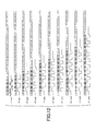
- the light of the multi-pulses emitted by the semiconductor laser LD 104 has a pulse width of approximately 1.0T on the top heating pulse Htop, and, has a pulse width of approximately 1.0T on the last cooling pulse Cend, when recording a mark of 3T (T is the period of the recording channel clock signal) which is the shortest mark length, as shown in FIG. 1B.
- a pair of a heating pulse Hmp having a pulse width of approximately 1.0T (Thmp) and a cooling pulse Cmp having a pulse width of approximately 1.0T (2T - Thmp) is inserted for increase of each two clock pulses 2T of the recording channel clock signal.
- a pair of a heating pulse Hmp having a pulse width of approximately 1.0T (Thmp) and a cooling pulse Cmp having a pulse width of approximately 1.0T (2T - Thmp) is inserted for increase of each two clock pulses 2T of the recording channel clock signal.
- combinations of the record marks of 4T and 5T; 6T and 7T; 8T and 9T; 10T and 11T have the heating pulses and cooling pulses in the same numbers respectively on the basis of the mark length of 3T. Therefore, while the total length in the conventional record waveform as shown in FIG. 1A is n-0.5T and, thus, it is fixed, the total length of multi-pulse sequence does not become fixed according to the fifth embodiment of the present invention.
- each combination which has the above-mentioned heating pulses and cooling pulses of the same number is set up into a recording waveform under a rule which is different, as shown in FIG. 3.
- a pulse width of the last cooling pulse Cend of a short mark data length (even number, for example, 4T) is approximately 0.75, and, thus, is narrow
- a pulse width of the last cooling pulse Cend of a long mark data length (odd number, for example, 5T) is approximately 1.25, and, thus, is wide.
- an erase pulse E2 for record mark is added to a top part of erase pulse E1 (erase power of Pe1) just behind the last cooling pulse Cend the short mark data length with the pulse width Te2 of approximately 1.0T.
- an erase pulse E3 for record mark is added to a top part of erase pulse E1 (erase power of Pe1) also just behind the last cooling pulse Cend of the long mark data length with the pulse width Te3 of also approximately 1.0T.
- ⁇ 2 ⁇ 1 + 0.1
- ⁇ 2 denotes a ratio of an erase power Pe2 on the above-mentioned erase pulse E2 with respect to the heating power Ph.
- ⁇ 2 0.65
- ⁇ 3 ⁇ 1 - 0.1
- ⁇ 3 denotes a ratio of an erase power Pe3 on the above-mentioned erase pulse E3 with respect to the heating power Ph.
- the short mark length is shorter than the long mark length by approximately 0.5T due to the difference in the pulse width on the last cooling pulse. Furthermore, as the above-mentioned ratio ⁇ 2 of the erase power Pe2 with respect to the heating power Ph is smaller than ⁇ 3 of the erase power Pe3 with respect to the heating power Ph by approximately 0.5, the tail edge of the record mark is erased more on the short mark length. Thereby, the record mark on the short mark length is further shorter than the record mark on the long mark length by 0.5T. Accordingly, the record mark on the short mark length is shorter than the record mark on the long mark length by total 1.0T, as shown in FIG. 3.
- the erase pulse E2 on the short mark length has the power level Pe2 higher than the original first erase power Pe1
- the erase pulse E3 on the long mark length has the power level Pe3 lower than the original first erase power Pe1.
- the pulse width Tcend2 on the last cooling pulse for the short data length is made shorter than the pulse width Tcend3 on the last cooling pulse for the long data length.
- the erase power Pe used for the phase-change optical disk 101 of AgInSbTe family is on the order in a range between 0.4 ⁇ Ph and 0.7 ⁇ Ph.
- the power is lower than this range, the erase power required for overwrite may not be obtained, but insufficient erase may arise, and thus, jitter of RF signal at a time of reproduction may get worse.
- the permissible number of times of overwrite in terms of degradation of the recording film may be degraded then.
- the pulse width Tcend of the last cooling pulse used on the phase-change optical disk 101 of AgInSbTe family is on the order of a range between 0.5T and 1.5T. Sufficient cooling time may not be obtained, and also, edge cannot be clearly formed after the record mark, thus jitter on the R F signal at a time of reproduction may get worse, when a shorter pulse width than this range is applied. When a longer pulse width than the above-mentioned range is applied conversely, an attainable temperature on the recording may be degraded, sudden cooling requirement may no longer be acquired enough, and thus jitter on the RF signal at a time of reproduction may get worse too.
- phase-change media such as in CD-RW and DVD-RW
- phase-change media are designed so that recording is made at a predetermined recording line speed according to a capability of an information recording/reproducing device applied.
- the recording line speed falls in a range between 4.8 m/s (four-time speed) and 12 m/s (ten-time speed).
- DVD-RW the recording line speed is in a range between 3.5 m/s (one-time speed) and 8.4 m/s (2.4-time speed).
- the recording line speed is in a range between 16-time speed and 32-time speed on CD-RW, and in a range between four-time speed and eight-time speed on DVD-RW.
- rising-up time and decaying-down time of recording waveform depend on the response speed of the LD driver part 102. Thus, it is limited to the order of 2 nanoseconds, in general, according to the response speed of the semiconductor laser LD 104 actually used, the wiring length of a flexible board mounted, and so forth.
- the pulse widths Th and Tcmp on heating pulse and cooling pulse become on the order of 5 nanoseconds, and, thereby, the portion on the rising-up/decaying-down increases, and, thereby, sufficient heating/cooling may not be performed.
- high accuracy setting should be preferably made by appropriately controlling the erase power Pe2/Pe3 and pulse width Tcend2/Tcend3 on the last cooling pulse according to the performance inherent to the information recording device, such that the different in mark data length between two mark data lengths having the same numbers of heating/cooling pulses be properly created.
- Such setting information may be determined previously on a particular recording medium, and then, may be embedded therein, which is then read out by an information recording/reproducing device before actual recording is made, and, thereby, the actual recording according to the correct setting information can be achieved.
- such setting information (on the above-mentioned ratios ⁇ 2, ⁇ 3 on the erase power and pulse widths Tcend2, Tcend3 on the last cooling pulse) is previously embedded into the optical disk 101, and is then detected by the following method:
- a wobble signal acquired from a meandering form added to a guidance slot formed in a substrate surface of the phase-change optical disk 101 is separated from a push-pull signal for acquiring a tracking error signal. Then, information peculiar to the recording medium given by frequency modulation (in the case of CD-RW), or phase modulation (in the case of DVD-RW), is restored, and, thus, the relevant setting information is obtained.
- a groove slot for acquiring a tracking error signal is formed on a disk, such as CD or DVD, and, thereon, a wobble signal is embedded by bending the grove slot in a staggering manner.
- This signal is detected on each recording line speed, through a programmable BPF, and then, frequency demodulation/phase demodulation is performed thereon so that the coded information is obtained by the decoding processing.
- This information may be embedded by a manner such that intermittent pits are formed into land parts, as known in the art (in case of DVD-RW).
- the information recording/reproducing device applied thus can obtain the ratios ⁇ 2, ⁇ 3 on the erase power of the optimal erase pulses and pulse widths Tcend2, Tcend3 on the last cooling pulses which can be obtained from the wobble signal, for record mark corresponding to each recording speed, from the relevant phase-change optical disk 101.
- the following method may be applied: That is, IDs and setting information including the above-mentioned recording conditions peculiar to the media of subject phase-change optical disks are previously stored in a memory part (recording condition preservation part) in which firmware of the information recording/reproducing device itself is stored. Then, the relevant setting information is selected from that stored in the memory part according to a medium ID recognized from the relevant disk 101 loaded therein.
- the ratios ⁇ 2, ⁇ 3 of erase power and pulse widths Tcend2, Tcend3 of the last cooling pulses may thus be updated any time if necessary, and, thus, the latest conditions of the device can be reflected by the setting information.
- the latest setting information may be updated by downloading it through the Internet.
- an optimum recording waveform corresponding to a particular recording speed on the phase-change optical disk 101 such as a CD-RW or a DVD-RW is fixed.
- a DVD-RW designed to be suitable to a range between one-time speed (3.5 m/s) and 2.6-time speed (8.5 m/s) as shown in FIG. 4, setting is made such that the pulse width Thmp of successive heating pulses following the top heating pulse of multi-pulse sequence may vary within a range between 0.3T and 0.55T.
- the pulse width Thmp of the heating pulse Hmp exceeds 0.55T, and, thereby, sufficient cooling speed cannot be secured, and, thus, jitter at a time of reproducing may become degraded.
- the multi-pulse sequence of heating pulses and cooling pulses having the same period as the recording channel clock period T is generated as in the related art as shown in FIG. 1A.
- a recording speed beyond the predetermined range such as three-time speed, or four-time speed, i.e., high-speed recording, recording is performed applying the configuration of multi-pulse sequence as described in the fifth embodiment as shown in FIG. 1B.
- the pulse width of each recording pulse (heating/cooling pulse) is widened, increase in the number of the heating pulses and cooling pulses in multi-pulse sequence in response to increase in the mark data length is performed in a different manner, and, also, as described above, the ratios ⁇ 2, ⁇ 3 on the erase pulses and pulse widths Tcend2, Tcend3 on the last cooling pulses are newly set.
- FIG. 13 shows a flow chart illustrating an example of general processing control of recording operation including such switching operation according to the sixth embodiment of the present invention.
- the thus-obtained pulse width Thmp is smaller than 0.55T (in a step S4).
- the conventional multi-pulse sequence (as sown in FIG. 1A) is chosen (in a step S5), and recording operation is performed accordingly (in a step S6).
- phase-change disk 101 any phase-change disk such as a CD-RW, a DVD-RW, or the like which is designed for a predetermined recording speed range may be applied.
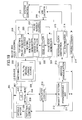
- FIG. 14 shows the information recording device embodying the scheme according to the above-mentioned sixth embodiment of the present invention.
- the rotation control mechanism 109 includes the spindle motor 105 which carries out rotation driving of the phase-change optical disk 101.
- the optical head 3 is provided with the semiconductor laser 104, object lens, and so forth, carries out condensing and applying the laser light onto the phase-change optical disk 101, and is movable (seek operation) along disk radius direction.
- An actuator control mechanism 110 is connected to an object lens and an outputting system of the optical head 3.
- a wobble detection part 12 includes the programmable BPF 111 and is connected to the above-mentioned actuator control mechanism 110.
- An address demodulation circuit 113 which demodulates addresses from the detected wobble signal is provided in the wobble detection part 112. With this address demodulation circuit 113, a recording clock generation part 115 including a PLL synthesizer circuit 114 is connected.
- a driving controller 116 is connected to the PLL synthesizer circuit 114.
- the rotation control mechanism 109, actuator control mechanism 110, wobble detection part 112, and address demodulation circuit 113 are also connected to the driving controller 116 connected to the system controller 117.
- an EFM encoder 118, a mark length counter 119, and a pulse number control part 120 are connected to the system controller 117.
- a recording pulse sequence control part 108 is connected to the EFM encoder 118, a mark length counter 119, and a pulse number control part 120.
- This recording pulse sequence control part 108 includes a heating pulse generation part (recording pulse generation part) 121 which generates the heating pulse control signal including top heating part and following heating/cooling parts; a first erase pulse generation part 22 which generates a first erase pulse control signal, a second and third erase pulse generation part (erase pulse generation part) 23 which generates second and third erase pulse control signals, an edge selector 24, and a pulse edge generation part 25.
- the LD driver part 102 In the output side of this recording pulse sequence control part 108, the LD driver part 102 is connected which controls switching of the respective driving current sources 106 on the heating power Ph, cooling power Pc, first erase power Pe1, second erase power Pe2 and third erase power Pe3, so as to drive the semiconductor laser LD 104 in the optical head 103 with the relevant power.
- address demodulation is performed from the wobble signal, obtained through separation detection with the programmable BPF 111 from the push pull signal acquired from the optical head 3, after controlling the rotation speed of the spindle motor 105 by the rotation control mechanism 109 into the recording line speed corresponding to the target recording speed. Also, the PLL synthesizer circuit 114 generates the recording channel clock signal.
- the recording channel clock signal and EFM data which is record information are input into the recording pulse sequence control part 108, and the heating pulse control signal containing the top heating pulse and the heating multi-pulses following thereto are generated by the heating pulse generation part 121 in the record pulse sequence control part 108. Further, the first erase pulse generation part 122 generates the erase pulse control signal which is the erase portion. Then, through the switching of the driving current source 106 set as providing the respective one of the above-mentioned Ph, Pe (Pe1) and Pc in the LD driver part 102, the LD light-emission waveform of recording pulse sequence can be obtained.
- a multi-stage pulse edge generation part 125 is provided with the heating pulse generation part 121, which has the resolution of 1/20 the recording channel clock period.
- the top heating pulse control signal and heating multi-pulse control signal are generated.
- a multi-stage delay circuit of the pulse edge generation part 125 may be formed of gate delay devices, ring oscillator and a PLL circuit having high resolution.
- edge pulses generated in a multi-stage delay circuit of a last cooling pulse generation part provided individually or the cooling pulse generation part in the heating pulse generation part 121 are input into the edge selector 124, and thus the rear edge of the last cooling pulse is defined by the edge pulse chosen by the system controller 117.
- the second or third erase pulse is generated immediately after the last cooling pulse.
- the whole recording multi-pulse sequence is thus created as a pulse group.
- the mark length counter 119 for carrying out calculation of the mark length of the EFM signal acquired from the EFM encoder 118 is provided, and thereby, whenever the mark count value increases by 2T, one pair of heating/cooling pulses are generated through the pulse number control part 120 in the recording pulse sequence control part 108.
- This operation becomes possible by selecting the rear edge for the top heating pulse by the edge selector 124, then, selecting the front edge of the following one of multi-pulses by the edge pulse generated by the following recording channel clock period, and, then, the rear edge of the one of multi-pulses is defined by the edge pulse generated by the subsequent channel clock period.
- a recording divided clock signal is generated through two-time dividing of the recording channel clock signal, and, therefrom, edge pulses are generated by using a multi-stage delay circuit. Then, selection is made therefrom, and, thus, necessary front and rear edges are defined. Thereby, a pair of heating/cooling pulses are generated for every 2T increase in the recording channel clock signal.
- the substantial frequency of multi-pulse generation part is set one half, and thus, further higher-speed recording operation can be attained.
- a recording device for a phase-change optical disk 1 like a CD-RW or a DVD-RW has a recording pulse sequence control part which additionally generates a pair of heating/cooling pulses for every increase of 1T of mark data length for a predetermined recording speed range. Then, setting is made on the top heating pulse width Thtop, heating multi-pulse width Thmp which follow thereto, the pulse width Tcend on the last cooling pulse, and each light-emission power as being the optimum values according to the recording selected from the predetermined record speed range.
- switching of the recording pulse sequence control part 108 is made so as to cause it to instead, additionally generates a pair of heating/cooling pulses for every 2T increase of the mark data length, when the specified recording speed exceeds the predetermined recording speed range.
- switching of the recording pulse sequence control part 108 is made so as to cause it to instead, additionally generates a pair of heating/cooling pulses for every 2T increase of the mark data length, when the specified recording speed exceeds the predetermined recording speed range.
- common information recording/reproducing device uses the semiconductor laser LD 104 as a light source, and as mentioned above, it is a limit that the rising-up/decaying-down time in light-emission waveform can be shortened up to approximately 2 nanoseconds in a cost-saving driving circuit.
- a phase-change medium of AgInSbTe used as a recording material therein it is necessary to also secure approximately about more than 2 nanoseconds as an establishment time of each light-emission power considering sufficient heating time and cooling time. Therefore, around 100 MHz is a limit of the recording channel clock frequency, and, thus, approximately four-time speed (26.16 MHz ⁇ 4) in DVD-RW is the limit in the related art.
- a substantial frequency of light-emission waveform can be reduced one half, and the information recording/reproducing device in each of this embodiment can perform high-speed recording up to 4-time speed or more about 8-time speed with a cost-saving configuration for DVD-RW, without increasing operation speed of the LD driver part 102 as light source driving part.
- the setting values on the top heating pulse width, pulse width of the last cooling pulse and so forth shown above are merely typical value, and, actually, should be optimized according to recording material, medium phase configuration, etc.
- the total length of record waveform and thus-formed mark length may differ according to difference in recording modulation scheme, diameter of optical spot of laser light, and recording density, the correspondence between the resulting mark length and applied recording waveform may be altered appropriately, for a particular case.
- FIG. 15 shows an example where the information recording/reproducing device having the configuration shown in FIG. 14 is applied in a personal computer 131 as an information processing device.
- the information recording device 133 such as that shown in FIG. 14 is built in the personal computer 131 as a DVD-RW drive.
- the personal computer 131 having the configuration shown in FIG. 15, as the above-described information recording device 133 is included therein, it is possible to secure a sufficient heating time and cooling time by a pulse control scheme of a simple configuration, and, also, predetermined mark lengths can be created without increasing operation speed of the light source driving unit. Accordingly, it is possible to achieve high-speed recording of recording speed higher than the conventional phase-change optical disk recording speed range, and, thereby, a very useful peripheral information storage device can be provided thereby.
- FIG. 19 shows an example of a configuration of an information recording/reproducing device according to the seventh embodiment of the present invention.
- this device records (overwrites) code data of CD-ROM format on a phase-change optical disk 201 which is an information recording medium, and performs mark edge (PWM) recording using EFM or EFM plus code (generally called EFM family code).
- PWM mark edge
- This information recording/reproducing device generates a pulse control signal based on a recording channel clock signal and EFM data at a time of recording.
- a semiconductor laser drive circuit (LD driver part) 202 drives a semiconductor laser (LD) 204 of an optical head 203 with a driving current according to the pulse control signal, and thus, causes the light source to emit a light-emission waveform of multi-pulse sequence, as shown in FIG. 5B.
- LD driver part drives a semiconductor laser (LD) 204 of an optical head 203 with a driving current according to the pulse control signal, and thus, causes the light source to emit a light-emission waveform of multi-pulse sequence, as shown in FIG. 5B.
- phase-change optical disk 201 driven and rotted by a spindle motor 205, while light of the light-emission waveform of the multi-pulse sequence from the semiconductor laser LD 104 is applied to the phase-change recording layer of the phase-change optical disk 201 through an optical system (not shown) in the optical head 203, and thus, record marks are formed onto the phase-change optical disk 201.
- this information recording/reproducing device drives the semiconductor laser LD 204 by the LD driver part 202, which is thus made to emit light at reproduction power (read power), the light of the reproduction power from the semiconductor laser LD4 is applied through the optical system onto the phase-change optical disk 201 in the optical head 203.
- a reproduction signal is obtained through reception of reflected light by a photoelectric device (not shown) through the optical system, and through photoelectric conversion.
- the light of the light-emission waveform of the multi-pulse sequence emitted by the semiconductor laser LD 204 at a time of recording includes a top heating pulse Htop followed by a plurality of heating pulses Hmp, and a plurality of cooling pulses Cmp occurring therebetween, respectively, as shown in FIG. 5B.
- the light-emission power Phtop of the top heating pulse Htop and the light-emission power Phmp of the following heating pulses Hmp are the same.
- a constant current corresponding to a light-emission power Ph of the top heating pulse Htop and the following heating multi-pulses Hmp from a driving current source 206 in the LD driver part 202 is supplied to the semiconductor laser LD 204 in the optical head 203, a constant current corresponding to a light-emission power Pcmp (Pc) of the cooling multi-pulses Cmp is also supplied thereto, and also, a light-emission power Pe of an erase pulse E is supplied thereto.
- the corresponding drive current source is made to be turned on/turned off, light is made to emit with the light-emission waveform of a multi-pulse sequence as shown in FIG. 16 by driving of the semiconductor laser LD 204.
- the light of the multi-pulses emitted by the semiconductor laser LD 204 has a pulse width of approximately 0.5T on the top heating pulse Htop, and, has a pulse width of approximately 0.5T on the last cooling pulse Cend, when recording a mark of 3T (T is the period of the recording channel clock signal) which is the shortest mark length, as shown in FIG. 5B.
- the seventh embodiment of the present invention a problem which may occur according to the conventional scheme shown in FIG. 5A where the heating pulse width is 0.2T while cooling pulse width is 0.8T, i.e., four times the heating pulse width, thereby, a sufficient sudden cooling requirement cannot be satisfied can be avoided.
- the phase-change disk 201 having the recording material of AgInSbTe or so a design has been made in general such that satisfactory recording can be achieved with the predetermined recording speed (with the predetermined recording channel clock frequency) with a ratio between heating pulse width and cooling pulse width only in a range between around 1:1 and 1:3.
- the above-mentioned ratio is approximately 1:2.
- the above-mentioned example of requirements in the ratio between heating pulse width and cooling pulse width only in a range between around 1:1 and 1:3 is that in case of a phase-change medium applied as a CD-RW or a DVD-RW actually used.
- ⁇ 11 denotes a ratio of an erase power Pe of an erase pulse E with respect to the heating power Ph of the heating pulses Htop and Hmp, shown in FIG. 16.
- a groove slot for acquiring a tracking error signal is formed on a disk, such as CD or DVD, and, thereon, a wobble signal is embedded by bending the grove slot in a staggering manner.
- This signal is detected on each recording line speed, through a programmable BPF, and then, frequency demodulation/phase demodulation is performed thereon so that the coded information is obtained by the decoding processing.
- This information may be embedded by a manner such that intermittent pits are formed into land parts, as known in the art (in case of DVD-RW).
- the information recording/reproducing device applied can obtain the setting information which can be obtained from the wobble signal, for record mark corresponding to each recording speed from the relevant phase-change optical disk 201.
- the following method may be applied: That is, IDs and setting information including the above-mentioned recording conditions peculiar to the media of subject phase-change optical disks are previously stored in a memory part (recording condition preservation part) in which firmware of the information recording/reproducing device itself is stored. Then, the relevant setting information is selected from that stored in the memory part according to a medium ID recognized from the relevant disk 201 loaded therein.
- the ratio ⁇ 11 of erase power and heating/cooling pulse widths, and whether one or two pairs of heating/cooling pulses be increase for increase in mark data length by every one clock pulse 1T of recording channel clock signal may be updated any time if necessary, and, thus, the latest conditions of the device can be reflected by the setting information.
- the latest setting information may be updated by downloading it through the Internet.
- an optimum recording waveform corresponding to a particular recording speed on the phase-change optical disk 201 such as a CD-RW or a DVD-RW is fixed.
- a DVD-RW designed to be suitable to a range between two-time speed (7 m/s) and five-time speed (16 m/s) as shown in FIG. 17, setting is made such that the pulse width Thmp of successive heating pulses Hmp following the top heating pulse of multi-pulse sequence may vary within a range between 0.25T and 0.55T.
- the pulse width Thmp of the heating pulse Hmp becomes less than 0.25T, and, thereby, the ratio of the heating pulse width with respect to the cooling pulse width becomes too small, and, thus, a sufficient cooling requirement cannot be secured, and, thus, jitter at a time of reproducing becomes degraded.
- the multi-pulse sequence of heating pulses and cooling pulses having the same period as the recording channel clock period is generated as in the related art as shown in FIG. 5A.
- a recording speed less than the predetermined range such as one time speed through three-time speed (CD-RW), or one-time speed (DVD-RW), i.e., low-speed recording
- CD-RW three-time speed
- DVD-RW one-time speed
- recording is performed applying the configuration of multi-pulse sequence as described in the seventh embodiment as shown in FIG. 5B.
- FIG. 18 shows a flow chart illustrating an example of general processing control of recording operation including such switching operation according to the eighth embodiment of the present invention.
- the pulse width Thmp is longer than 0.25T (in a step S14).
- the conventional multi-pulse sequence (as sown in FIG. 5A) is chosen (in a step S15), and recording operation is performed accordingly (in a step S16).
- phase-change disk 201 any a phase-change disk such as a CD-RW, a DVD-RW, or the like which is designed for a predetermined recording speed range may be applied.
- FIG. 19 shows the information recording device embodying the scheme according to the above-mentioned eighth embodiment of the present invention.
- the rotation control mechanism 209 includes the spindle motor 205 which carries out rotation driving of the phase-change optical disk 201.
- the optical head 203 is provided with the semiconductor laser 204, object lens, and so forth, carries out condensing and applying the laser light onto the phase-change optical disk 201, and is movable (seek operation) along disk radius direction.
- An actuator control mechanism 210 is connected to an object lens drive and an outputting system of the optical head 203.
- a wobble detection part 212 includes the programmable BPF 211 and is connected to the above-mentioned actuator control mechanism 210.
- An address demodulation circuit 213 demodulates addresses from the detected wobble signal in the wobble detection part 212. With this address demodulation circuit 213, a recording clock generation part 215 including a PLL synthesizer circuit 214 is connected. Further, a driving controller 216 is connected to the PLL synthesizer circuit 214.
- the rotation control mechanism 209, actuator control mechanism 210, wobble detection part 212, and address demodulation circuit 213 are also connected to the driving controller 216 connected to the system controller 217.
- This recording pulse sequence control part 208 includes a top heating pulse generation part 219 generating a heating pulse control signal including the top heating part, and a first, second heating pulse generation part 220 which generates the heating pulse control signal including the following heating/cooling parts, an erase pulse generation part 221 which generates an erase pulse control signal for erase pulse, an edge selector 223, and a pulse number control part 224.
- the LD driver part 202 In the output side of this recording pulse sequence control part 208, the LD driver part 202 is connected which controls switching of the respective driving current sources 206 on the heating power Ph, cooling power Pc, erase power Pe so as to drive the semiconductor laser LD 204 in the optical head 203 with the relevant power.
- a mark length counter is also provided in the recording pulse sequence control part 208 for counting for the mark data length based on the output of the EFM encoder 218.
- address demodulation is performed from the wobble signal, obtained through separation detection with the programmable BPF 211 from the push pull signal acquired from the optical head 203, after controlling the rotation speed of the spindle motor 205 by the rotation control mechanism 209 into the recording line speed corresponding to the target recording speed. Also, the PLL synthesizer circuit 214 generates the recording channel clock signal.
- the recording channel clock signal and EFM data which is record information are input into the recording pulse sequence control part 208, and the heating pulse control signal containing the top heating pulse is generated by the heating pulse generation part 219 in the record pulse sequence control part 208.
- the first, second heating pulse-pulse generation part 220 generates the heating multi-pulse control signal for the heating/cooling pulses following to the top heating pulse every period of the recording channel clock signal.
- the erase pulse generation part 221 generates the erase pulse control signal which is the erase portion. Then, through the switching of the driving current source 206 set to provide the respective one of the above-mentioned Ph, Pe and Pc in the LD driver part 202, the LD light-emission waveform of recording pulse sequence can be obtained.
- a multi-stage pulse edge generation part 223 is provided in each of the top heating pulse generation part 219 and first, second heating pulse series generation part 220 which has the resolution of 1/20 of the recording channel clock period.
- a multi-stage delay circuit is included in the pulse edge generation part 223 and may be formed of gate delay devices, ring oscillator and a PLL circuit having high resolution.
- the multi-pulse sequence synchronized with the recording channel clock signal is created by the thus-generated heating pulses, and, the pulse width of cooling pulses are also simultaneously determined by duty with respect to the heating multi-pulse width.
- edge pulses generated in the multi-stage delay circuit of the last cooling pulse generation part provided individually are input into the edge selector, and thus the rear edge of the last cooling pulse is defined by the edge pulse chosen by the system controller 217.
- edge pulses generated in another multi-stage delay circuit are selected by the edge selector 222, and thereby, a rear edge of a predetermined last cooling pulse is defined.
- the whole recording multi-pulse sequence is thus created as a pulse group.
- the pulse number control part 224 controls the number of pulses on the heating multi-pulse control signal according to the EFM signal and the recording channel clock period T. Thereby, from each of the rising edge and decaying edge of the recording channel clock signal, the heating multi-pulse signal is generated for the predetermined pulse width set by the edge selector. At this time, as a result of the system controller 217 selecting one or both edges of the recording channel clock pulse, whether the control signal for one pair of heating/cooling pulses be generated or the control signal for two pairs of heating/cooling pulses be generated is determined for each clock pulse.
- a recording multiplied clock signal is generated through two-time multiplying of the recording channel clock signal, and, therefrom, edge pulses are generated by using a multi-stage delay circuit. Then, selection is made therefrom, and, thus, front and rear edges are defined by an edge selector. Thereby, two pairs of heating/cooling pulses are generated every 1T increase in the recording channel clock signal.
- the substantial operation frequency of recording pulse sequence control part is set double. However, as the recording channel clock frequency itself is lowered in such a low-speed recording, the operation frequency does not increase much substantially. According to this configuration, further lower-speed recording operation can be attained without increasing the number of types of information recording medium.
- a recording device for a phase-change optical disk 201 like a CD-RW or a DVD-RW has a recording pulse sequence control part which additionally generates a pair of heating/cooling pulses every increase of 1T of mark data length for a predetermined recording speed range. Then, setting is made on the top heating pulse width Thtop, heating multi-pulse width Thmp which follows thereto, the pulse width Tcend on the last cooling pulse, and each light-emission power as being the optimum values according to the recording speed selected from the predetermined record speed range.
- switching of the recording pulse sequence control part 208 is made so as to cause it to additionally generate two pair of heating/cooling pulses every 1T increase of the mark data length, when the selected recording speed becomes less than the predetermined recording speed range.
- switching of the recording pulse sequence control part 208 is made so as to cause it to additionally generate two pair of heating/cooling pulses every 1T increase of the mark data length, when the selected recording speed becomes less than the predetermined recording speed range.
- the setting values on the top heating pulse width, pulse width of the last cooling pulse and so forth shown above are merely typical value, and, actually, should be optimized according to recording material, medium phase configuration, etc.
- the total length of record waveform and formed mark length may differ according to difference in recording modulation scheme, diameter of optical spot of laser light, and recording density, the correspondence between the mark length and recording waveform may be altered appropriately for a particular case.
- FIG. 20 shows an example where the configuration shown in FIG. 19 is applied with a personal computer 231 as an information processing device.
- the information recording device 233 such as that shown in FIG. 19 is built in the personal computer 231 as a DVD-RW drive.
- the personal computer 231 having the configuration shown in FIG. 20, as the above-described information recording device 233 is included therein, it is possible to secure a sufficient heating time and cooling time by the pulse control scheme of simple configuration, and, also, predetermined mark lengths can be created without increasing operation speed of the light source driving unit. Accordingly, it is possible to achieve low-speed recording of recording speed lower than the conventional phase-change optical disk recording speed range, and, thereby, a very useful peripheral information storage device can be provided thereby.
Applications Claiming Priority (6)
| Application Number | Priority Date | Filing Date | Title |
|---|---|---|---|
| JP2001113459 | 2001-04-12 | ||
| JP2001113459A JP2002312934A (ja) | 2001-04-12 | 2001-04-12 | 情報記録方法及び情報記録装置 |
| JP2001135211A JP4480295B2 (ja) | 2001-05-02 | 2001-05-02 | 情報記録方法、情報記録装置及び情報処理装置 |
| JP2001135211 | 2001-05-02 | ||
| JP2001287272 | 2001-09-20 | ||
| JP2001287272A JP4643086B2 (ja) | 2001-09-20 | 2001-09-20 | 情報記録方法及び情報記録装置 |
Publications (3)
| Publication Number | Publication Date |
|---|---|
| EP1249834A2 true EP1249834A2 (de) | 2002-10-16 |
| EP1249834A3 EP1249834A3 (de) | 2005-05-04 |
| EP1249834B1 EP1249834B1 (de) | 2012-09-12 |
Family
ID=27346520
Family Applications (1)
| Application Number | Title | Priority Date | Filing Date |
|---|---|---|---|
| EP02252572A Expired - Fee Related EP1249834B1 (de) | 2001-04-12 | 2002-04-10 | Informationsaufzeichnung mit wirksamen Pulssteuerungsschema |
Country Status (2)
| Country | Link |
|---|---|
| US (1) | US6801240B2 (de) |
| EP (1) | EP1249834B1 (de) |
Cited By (11)
| Publication number | Priority date | Publication date | Assignee | Title |
|---|---|---|---|---|
| EP1300836A2 (de) * | 2001-10-02 | 2003-04-09 | Matsushita Electric Industrial Co., Ltd. | Optisches Informationsaufzeichnungsverfahren, optisches Informationsaufzeichnungs- und -Wiedergabegerät, und optisches Informationsaufzeichnungsmedium |
| NL1020814C2 (nl) * | 2001-12-31 | 2004-04-06 | M E T Technology Co | Werkwijze voor het verhogen van de succesgraad van het opnemen op compact disc. |
| EP1422712A2 (de) * | 2002-11-21 | 2004-05-26 | Matsushita Electric Industrial Co., Ltd. | Aufzeichnungs-/Wiedergabeverfahren und Aufzeichnungs-/Wiedergabevorrichtung |
| EP1434206A2 (de) * | 2002-12-27 | 2004-06-30 | Ricoh Company, Ltd. | Optisches Aufzeichnungsmedium vom Phasenwechseltyp und Aufzeichnungsverfahren dafür |
| EP1498885A2 (de) * | 2003-07-15 | 2005-01-19 | Ricoh Company | Informationsaufzeichnungsverfahren und Informationsaufzeichnungsgerät |
| WO2005010873A1 (en) * | 2003-07-24 | 2005-02-03 | Koninklijke Philips Electronics N.V. | Method and device for transforming a first set of write parameters of a write strategy into a second set of write parameters at a different recording speed |
| EP1598816A1 (de) * | 2003-02-28 | 2005-11-23 | Pioneer Corporation | Informationsaufzeichnungseinrichtung und informationsaufzeichnungsverfahren |
| EP1425740B1 (de) * | 2001-09-10 | 2006-11-02 | Pioneer Corporation | Optisches aufzeichnungsgerät und methode zur optischen aufzeichnung |
| US7719937B2 (en) | 2004-07-16 | 2010-05-18 | Koninklijke Philips Electronics N.V. | Method of optimizing the write power for recording marks in an information layer of a record carrier and recording device using such an optimizing method |
| EP2299441A3 (de) * | 2003-02-19 | 2011-07-13 | Victor Company Of Japan, Ltd. | Optisches Aufzeichnungsverfahren und optische Aufzeichnungsvorrichtung |
| US8004947B2 (en) | 2005-06-03 | 2011-08-23 | Koninklijke Philips Electronics N.V. | Method and device for recording marks in an information layer of an optical disc |
Families Citing this family (24)
| Publication number | Priority date | Publication date | Assignee | Title |
|---|---|---|---|---|
| JP3521141B2 (ja) | 2002-01-08 | 2004-04-19 | 株式会社リコー | 情報記録装置 |
| KR100455377B1 (ko) * | 2002-01-18 | 2004-11-06 | 삼성전자주식회사 | 다양한 광 매체에 적합한 기록 펄스 발생 장치 및 방법 |
| US7376064B2 (en) * | 2002-02-25 | 2008-05-20 | Samsung Electronics Co., Ltd. | Method and apparatus for recording data on optical recording medium |
| US7260053B2 (en) * | 2002-04-02 | 2007-08-21 | Ricoh Company, Ltd. | Optical recording medium, process for manufacturing the same, sputtering target for manufacturing the same, and optical recording process using the same |
| JP2003317395A (ja) * | 2002-04-15 | 2003-11-07 | Pioneer Electronic Corp | 情報記録装置および情報記録方法 |
| JP3820181B2 (ja) * | 2002-05-10 | 2006-09-13 | 株式会社リコー | 記録ストラテジ生成方法及び光情報記録媒体 |
| JP4249590B2 (ja) * | 2002-11-18 | 2009-04-02 | 株式会社リコー | 光情報記録媒体およびその製造方法 |
| TWI261825B (en) * | 2002-12-16 | 2006-09-11 | Hitachi Maxell | Data recording method and data recording medium |
| JP3996051B2 (ja) * | 2002-12-18 | 2007-10-24 | 株式会社リコー | 光記録方法 |
| JP2004220663A (ja) * | 2003-01-10 | 2004-08-05 | Pioneer Electronic Corp | 光ピックアップ装置、光ビーム出射制御方法、並びに、光ビーム出射制御プログラムおよびそれを記録した記録媒体 |
| CN101261845B (zh) * | 2003-07-18 | 2010-07-21 | 三菱化学媒体股份有限公司 | 光记录方法 |
| JP3572068B1 (ja) * | 2003-08-28 | 2004-09-29 | 株式会社リコー | 情報記録方法、光情報記録媒体及び情報記録装置 |
| WO2005038788A1 (ja) | 2003-10-17 | 2005-04-28 | Mitsubishi Kagaku Media Co., Ltd. | 光記録方法 |
| JP4102289B2 (ja) * | 2003-11-07 | 2008-06-18 | 株式会社日立製作所 | 情報記録方法、情報記録装置及び評価装置 |
| JP4136980B2 (ja) * | 2004-03-19 | 2008-08-20 | 株式会社リコー | 多層相変化型情報記録媒体及びその記録再生方法 |
| JP4382646B2 (ja) * | 2004-05-17 | 2009-12-16 | 株式会社リコー | 光記録媒体とその製造方法 |
| US20050270959A1 (en) * | 2004-06-02 | 2005-12-08 | Hiroyuki Iwasa | Recording method for optical recording medium, and optical recording apparatus |
| DE602006007514D1 (de) * | 2005-03-02 | 2009-08-13 | Ricoh Kk | Optische aufzeichnungsmethode und aufzeichnungsvorrichtung |
| WO2006132096A1 (en) * | 2005-06-06 | 2006-12-14 | Ricoh Company, Ltd. | Phase-change type optical recording medium and reproduction method and apparatus for such a recording medium |
| US8014096B2 (en) * | 2009-03-13 | 2011-09-06 | Hitachi Global Storage Technologies, Netherlands B.V. | Combined bulk thermal-assister and bulk eraser |
| US8289821B1 (en) | 2010-12-21 | 2012-10-16 | Western Digital (Fremont), Llc | Method and system for pulsing EAMR disk drives |
| US8908480B1 (en) | 2012-09-28 | 2014-12-09 | Western Digital Technologies, Inc. | Method and system for providing an energy assisted magnetic recording disk drive using a pulsed laser light |
| US8891341B1 (en) | 2013-03-11 | 2014-11-18 | Western Digital Technologies, Inc. | Energy assisted magnetic recording disk drive using modulated laser light |
| US9064525B2 (en) | 2013-11-26 | 2015-06-23 | Western Digital Technologies, Inc. | Disk drive comprising laser transmission line optimized for heat assisted magnetic recording |
Citations (1)
| Publication number | Priority date | Publication date | Assignee | Title |
|---|---|---|---|---|
| JPH09134525A (ja) | 1995-11-08 | 1997-05-20 | Ricoh Co Ltd | 情報記録方式 |
Family Cites Families (17)
| Publication number | Priority date | Publication date | Assignee | Title |
|---|---|---|---|---|
| JP3124720B2 (ja) | 1995-04-14 | 2001-01-15 | 株式会社リコー | 情報記録再生方法、情報記録再生装置及び情報記録媒体 |
| JP2534988B2 (ja) | 1986-04-30 | 1996-09-18 | 株式会社リコー | 情報信号再生方法 |
| US5105416A (en) | 1988-03-14 | 1992-04-14 | Ricoh Company, Ltd. | Optical disc recording/reproducing control |
| JP2734066B2 (ja) * | 1989-03-13 | 1998-03-30 | 株式会社ニコン | 光媒体記録装置 |
| JP2815998B2 (ja) | 1990-03-14 | 1998-10-27 | 株式会社リコー | 光学的情報の再生方法 |
| JPH0528498A (ja) | 1991-07-19 | 1993-02-05 | Ricoh Co Ltd | 光照射方法並びに光学的情報記録媒体及びそれを用いた記録方法と再生方法 |
| JPH05120727A (ja) | 1991-10-28 | 1993-05-18 | Ricoh Co Ltd | 光記録媒体及び該媒体に情報を記録または再生する方法 |
| JP2899551B2 (ja) | 1994-09-22 | 1999-06-02 | 株式会社リコー | 情報記録方法及び情報記録装置 |
| DE69529442T2 (de) | 1994-09-22 | 2003-11-20 | Ricoh Kk | Informationsaufzeichnungsverfahren und -vorrichtung |
| JP3124721B2 (ja) | 1995-09-11 | 2001-01-15 | 株式会社リコー | 光学的情報記録再生方法及び光学的情報記録再生装置 |
| US5732062A (en) * | 1995-10-16 | 1998-03-24 | Ricoh Company, Ltd. | Information recording apparatus, method and computer program product |
| JPH11175976A (ja) | 1997-12-09 | 1999-07-02 | Hitachi Ltd | 情報記録装置 |
| JP3734621B2 (ja) | 1998-07-03 | 2006-01-11 | 株式会社リコー | 光情報記録方法及びその装置 |
| JP4063978B2 (ja) | 1998-07-03 | 2008-03-19 | 株式会社リコー | 情報記録方法 |
| US6487149B1 (en) | 1998-10-09 | 2002-11-26 | Ricoh Company, Ltd. | Optical recording and reproducing methods for optical disk |
| CZ2001809A3 (cs) * | 1999-07-07 | 2001-08-15 | Koninklijke Philips Electronics N. V. | Způsob a zařízení pro záznam značek v informační vrstvě optického nosiče záznamu |
| US6459666B1 (en) * | 1999-09-06 | 2002-10-01 | Ricoh Company, Ltd. | Information recording apparatus and method |
-
2002
- 2002-04-10 US US10/119,193 patent/US6801240B2/en not_active Expired - Lifetime
- 2002-04-10 EP EP02252572A patent/EP1249834B1/de not_active Expired - Fee Related
Patent Citations (1)
| Publication number | Priority date | Publication date | Assignee | Title |
|---|---|---|---|---|
| JPH09134525A (ja) | 1995-11-08 | 1997-05-20 | Ricoh Co Ltd | 情報記録方式 |
Cited By (28)
| Publication number | Priority date | Publication date | Assignee | Title |
|---|---|---|---|---|
| EP1425740B1 (de) * | 2001-09-10 | 2006-11-02 | Pioneer Corporation | Optisches aufzeichnungsgerät und methode zur optischen aufzeichnung |
| US7474601B2 (en) | 2001-09-10 | 2009-01-06 | Pioneer Corporation | Information recording apparatus and information recording method |
| US7349316B2 (en) | 2001-09-10 | 2008-03-25 | Pioneer Corporation | Information recording apparatus and information recording method |
| EP1783750A1 (de) * | 2001-09-10 | 2007-05-09 | Pioneer Corporation | Optisches Aufzeichungsgerät und Verfahren zur optischen Aufzeichnung |
| EP1783749A1 (de) * | 2001-09-10 | 2007-05-09 | Pioneer Corporation | Optisches Aufzeichnungsgerät und Verfahren zur optischen Aufzeichung |
| EP1729292A3 (de) * | 2001-09-10 | 2007-04-18 | Pioneer Corporation | Vorrichtung und Verfahren zur Informationsaufzeichnung |
| EP1729292A2 (de) * | 2001-09-10 | 2006-12-06 | Pioneer Corporation | Vorrichtung und Verfahren zur Informationsaufzeichnung |
| EP1300836A2 (de) * | 2001-10-02 | 2003-04-09 | Matsushita Electric Industrial Co., Ltd. | Optisches Informationsaufzeichnungsverfahren, optisches Informationsaufzeichnungs- und -Wiedergabegerät, und optisches Informationsaufzeichnungsmedium |
| EP1300836A3 (de) * | 2001-10-02 | 2006-04-19 | Matsushita Electric Industrial Co., Ltd. | Optisches Informationsaufzeichnungsverfahren, optisches Informationsaufzeichnungs- und -Wiedergabegerät, und optisches Informationsaufzeichnungsmedium |
| NL1020814C2 (nl) * | 2001-12-31 | 2004-04-06 | M E T Technology Co | Werkwijze voor het verhogen van de succesgraad van het opnemen op compact disc. |
| US7529168B2 (en) | 2002-11-21 | 2009-05-05 | Panasonic Corporation | Recording/reproduction method and recording/reproduction apparatus |
| EP1422712A3 (de) * | 2002-11-21 | 2005-05-04 | Matsushita Electric Industrial Co., Ltd. | Aufzeichnungs-/Wiedergabeverfahren und Aufzeichnungs-/Wiedergabevorrichtung |
| EP1422712A2 (de) * | 2002-11-21 | 2004-05-26 | Matsushita Electric Industrial Co., Ltd. | Aufzeichnungs-/Wiedergabeverfahren und Aufzeichnungs-/Wiedergabevorrichtung |
| EP1434206A3 (de) * | 2002-12-27 | 2005-11-23 | Ricoh Company, Ltd. | Optisches Aufzeichnungsmedium vom Phasenwechseltyp und Aufzeichnungsverfahren dafür |
| US7242657B2 (en) | 2002-12-27 | 2007-07-10 | Ricoh Company, Ltd. | Phase change type optical recording medium and recording method therefor |
| EP1434206A2 (de) * | 2002-12-27 | 2004-06-30 | Ricoh Company, Ltd. | Optisches Aufzeichnungsmedium vom Phasenwechseltyp und Aufzeichnungsverfahren dafür |
| US9025424B2 (en) | 2003-02-19 | 2015-05-05 | JVC Kenwood Corporation | Optical recording method, optical recording medium, optical recording medium recording apparatus, optical recording apparatus, optical disk, and optical disk recording/reproducing apparatus |
| EP2299441A3 (de) * | 2003-02-19 | 2011-07-13 | Victor Company Of Japan, Ltd. | Optisches Aufzeichnungsverfahren und optische Aufzeichnungsvorrichtung |
| EP1598816A4 (de) * | 2003-02-28 | 2008-12-31 | Pioneer Corp | Informationsaufzeichnungseinrichtung und informationsaufzeichnungsverfahren |
| US7586823B2 (en) | 2003-02-28 | 2009-09-08 | Pioneer Corporation | Information recording apparatus and information recording method |
| EP1598816A1 (de) * | 2003-02-28 | 2005-11-23 | Pioneer Corporation | Informationsaufzeichnungseinrichtung und informationsaufzeichnungsverfahren |
| US7426166B2 (en) | 2003-07-15 | 2008-09-16 | Ricoh Company, Ltd. | Information recording method and information recording apparatus that can achieve uniform signal characteristics and overwriting characteristics over an entire surface of an optical disk medium |
| EP1498885A2 (de) * | 2003-07-15 | 2005-01-19 | Ricoh Company | Informationsaufzeichnungsverfahren und Informationsaufzeichnungsgerät |
| EP1498885A3 (de) * | 2003-07-15 | 2007-10-10 | Ricoh Company | Informationsaufzeichnungsverfahren und Informationsaufzeichnungsgerät |
| US7848201B2 (en) | 2003-07-15 | 2010-12-07 | Ricoh Company, Ltd. | Information recording apparatus that can achieve uniform signal characteristics and overwriting characteristics over an entire surface of an optical disk medium |
| WO2005010873A1 (en) * | 2003-07-24 | 2005-02-03 | Koninklijke Philips Electronics N.V. | Method and device for transforming a first set of write parameters of a write strategy into a second set of write parameters at a different recording speed |
| US7719937B2 (en) | 2004-07-16 | 2010-05-18 | Koninklijke Philips Electronics N.V. | Method of optimizing the write power for recording marks in an information layer of a record carrier and recording device using such an optimizing method |
| US8004947B2 (en) | 2005-06-03 | 2011-08-23 | Koninklijke Philips Electronics N.V. | Method and device for recording marks in an information layer of an optical disc |
Also Published As
| Publication number | Publication date |
|---|---|
| EP1249834B1 (de) | 2012-09-12 |
| EP1249834A3 (de) | 2005-05-04 |
| US20020196324A1 (en) | 2002-12-26 |
| US6801240B2 (en) | 2004-10-05 |
Similar Documents
| Publication | Publication Date | Title |
|---|---|---|
| EP1249834B1 (de) | Informationsaufzeichnung mit wirksamen Pulssteuerungsschema | |
| EP0977184B1 (de) | Adaptive Schreibvorrichtung und -Schaltung für ein hochdichtes optisches Aufzeichnungsgerät | |
| JP3138610B2 (ja) | 相変化型光ディスク用記録方法 | |
| JPH09134525A (ja) | 情報記録方式 | |
| JP4480295B2 (ja) | 情報記録方法、情報記録装置及び情報処理装置 | |
| EP1557828A1 (de) | Optisches informationsaufzeichnungsmedium,optische informationsaufzeichnungseinrichutng und optisches informationsaufzeichnungsmedium | |
| US7391697B2 (en) | Adaptive writing method for high-density optical recording apparatus and circuit thereof | |
| US7336588B2 (en) | Method of and apparatus for recording data on optical recording medium | |
| KR100911140B1 (ko) | 광 기록매체에 데이터를 기록하는 방법 및 그 장치 | |
| KR100354737B1 (ko) | 고밀도 광기록기기를 위한 적응적인 기록방법 및 그 회로 | |
| JP3522730B2 (ja) | 情報記録方法、光ヘッド及び情報記録装置 | |
| US8315138B2 (en) | Adaptive writing method for high-density optical recording apparatus and circuit thereof | |
| JP3864679B2 (ja) | 記録装置及び記録方法 | |
| US20040190431A1 (en) | Optical recording medium, method and apparatus for recording data thereon | |
| JP3508932B2 (ja) | 情報記録方法、光ヘッド及び情報記録装置 | |
| JP2006528817A (ja) | ライトストラテジの第一の書込みパラメータのセットを異なる記録速度での第二の書込みパラメータのセットに変換する方法及び装置 | |
| JP4524978B2 (ja) | 光記録装置 | |
| JP4643086B2 (ja) | 情報記録方法及び情報記録装置 | |
| JPH06251375A (ja) | 光記録装置におけるレーザー駆動方式及びその駆動装置 | |
| JP2005032295A (ja) | 情報の記録方法 | |
| JP2004227634A (ja) | Cd−rディスクの記録装置および記録方法 | |
| KR20040067778A (ko) | 광 기록 매체, 이에 데이터를 기록하는 방법 및 그 장치 | |
| KR20040028317A (ko) | 광 기록매체에 데이터를 기록하는 방법 및 그 장치 |
Legal Events
| Date | Code | Title | Description |
|---|---|---|---|
| PUAI | Public reference made under article 153(3) epc to a published international application that has entered the european phase |
Free format text: ORIGINAL CODE: 0009012 |
|
| 17P | Request for examination filed |
Effective date: 20020510 |
|
| AK | Designated contracting states |
Kind code of ref document: A2 Designated state(s): AT BE CH CY DE DK ES FI FR GB GR IE IT LI LU MC NL PT SE TR |
|
| AX | Request for extension of the european patent |
Free format text: AL;LT;LV;MK;RO;SI |
|
| RIC1 | Information provided on ipc code assigned before grant |
Ipc: 7G 11B 7/006 A |
|
| PUAL | Search report despatched |
Free format text: ORIGINAL CODE: 0009013 |
|
| RIC1 | Information provided on ipc code assigned before grant |
Ipc: 7G 11B 7/0045 B Ipc: 7G 11B 7/006 A |
|
| AK | Designated contracting states |
Kind code of ref document: A3 Designated state(s): AT BE CH CY DE DK ES FI FR GB GR IE IT LI LU MC NL PT SE TR |
|
| AX | Request for extension of the european patent |
Extension state: AL LT LV MK RO SI |
|
| AKX | Designation fees paid |
Designated state(s): DE FR GB |
|
| 17Q | First examination report despatched |
Effective date: 20080924 |
|
| GRAP | Despatch of communication of intention to grant a patent |
Free format text: ORIGINAL CODE: EPIDOSNIGR1 |
|
| GRAJ | Information related to disapproval of communication of intention to grant by the applicant or resumption of examination proceedings by the epo deleted |
Free format text: ORIGINAL CODE: EPIDOSDIGR1 |
|
| GRAC | Information related to communication of intention to grant a patent modified |
Free format text: ORIGINAL CODE: EPIDOSCIGR1 |
|
| GRAP | Despatch of communication of intention to grant a patent |
Free format text: ORIGINAL CODE: EPIDOSNIGR1 |
|
| GRAS | Grant fee paid |
Free format text: ORIGINAL CODE: EPIDOSNIGR3 |
|
| GRAA | (expected) grant |
Free format text: ORIGINAL CODE: 0009210 |
|
| RIN1 | Information on inventor provided before grant (corrected) |
Inventor name: ABE, MICHIHARU Inventor name: SHINOTSUKA, MICHIAKI Inventor name: YOKOI, KENYA |
|
| AK | Designated contracting states |
Kind code of ref document: B1 Designated state(s): DE FR GB |
|
| REG | Reference to a national code |
Ref country code: GB Ref legal event code: FG4D |
|
| REG | Reference to a national code |
Ref country code: DE Ref legal event code: R096 Ref document number: 60243684 Country of ref document: DE Effective date: 20121108 |
|
| PLBE | No opposition filed within time limit |
Free format text: ORIGINAL CODE: 0009261 |
|
| STAA | Information on the status of an ep patent application or granted ep patent |
Free format text: STATUS: NO OPPOSITION FILED WITHIN TIME LIMIT |
|
| 26N | No opposition filed |
Effective date: 20130613 |
|
| REG | Reference to a national code |
Ref country code: DE Ref legal event code: R097 Ref document number: 60243684 Country of ref document: DE Effective date: 20130613 |
|
| REG | Reference to a national code |
Ref country code: FR Ref legal event code: PLFP Year of fee payment: 15 |
|
| REG | Reference to a national code |
Ref country code: FR Ref legal event code: PLFP Year of fee payment: 16 |
|
| REG | Reference to a national code |
Ref country code: FR Ref legal event code: PLFP Year of fee payment: 17 |
|
| PGFP | Annual fee paid to national office [announced via postgrant information from national office to epo] |
Ref country code: DE Payment date: 20190418 Year of fee payment: 18 |
|
| PGFP | Annual fee paid to national office [announced via postgrant information from national office to epo] |
Ref country code: FR Payment date: 20190424 Year of fee payment: 18 |
|
| PGFP | Annual fee paid to national office [announced via postgrant information from national office to epo] |
Ref country code: GB Payment date: 20190418 Year of fee payment: 18 |
|
| REG | Reference to a national code |
Ref country code: DE Ref legal event code: R119 Ref document number: 60243684 Country of ref document: DE |
|
| PG25 | Lapsed in a contracting state [announced via postgrant information from national office to epo] |
Ref country code: DE Free format text: LAPSE BECAUSE OF NON-PAYMENT OF DUE FEES Effective date: 20201103 Ref country code: FR Free format text: LAPSE BECAUSE OF NON-PAYMENT OF DUE FEES Effective date: 20200430 |
|
| GBPC | Gb: european patent ceased through non-payment of renewal fee |
Effective date: 20200410 |
|
| PG25 | Lapsed in a contracting state [announced via postgrant information from national office to epo] |
Ref country code: GB Free format text: LAPSE BECAUSE OF NON-PAYMENT OF DUE FEES Effective date: 20200410 |