EP1432885B1 - Dispositif pour regler la position d'une vitre de vehicule automobile deplacee par un leve-vitre a cable double brin - Google Patents
Dispositif pour regler la position d'une vitre de vehicule automobile deplacee par un leve-vitre a cable double brin Download PDFInfo
- Publication number
- EP1432885B1 EP1432885B1 EP02776810A EP02776810A EP1432885B1 EP 1432885 B1 EP1432885 B1 EP 1432885B1 EP 02776810 A EP02776810 A EP 02776810A EP 02776810 A EP02776810 A EP 02776810A EP 1432885 B1 EP1432885 B1 EP 1432885B1
- Authority
- EP
- European Patent Office
- Prior art keywords
- cable
- bowden
- adjusting
- length
- crossed
- Prior art date
- Legal status (The legal status is an assumption and is not a legal conclusion. Google has not performed a legal analysis and makes no representation as to the accuracy of the status listed.)
- Expired - Lifetime
Links
- 238000004904 shortening Methods 0.000 claims description 7
- 210000002445 nipple Anatomy 0.000 claims description 4
- 238000006073 displacement reaction Methods 0.000 description 7
- 230000005540 biological transmission Effects 0.000 description 3
- 238000004519 manufacturing process Methods 0.000 description 3
- 241001074085 Scophthalmus aquosus Species 0.000 description 2
- 230000006978 adaptation Effects 0.000 description 2
- 239000000969 carrier Substances 0.000 description 2
- 230000008878 coupling Effects 0.000 description 2
- 238000010168 coupling process Methods 0.000 description 2
- 238000005859 coupling reaction Methods 0.000 description 2
- 239000005357 flat glass Substances 0.000 description 2
- 238000010276 construction Methods 0.000 description 1
- 230000000694 effects Effects 0.000 description 1
- 230000002349 favourable effect Effects 0.000 description 1
- 238000009434 installation Methods 0.000 description 1
- 239000002184 metal Substances 0.000 description 1
- 230000036316 preload Effects 0.000 description 1
Images


Classifications
-
- B—PERFORMING OPERATIONS; TRANSPORTING
- B60—VEHICLES IN GENERAL
- B60J—WINDOWS, WINDSCREENS, NON-FIXED ROOFS, DOORS, OR SIMILAR DEVICES FOR VEHICLES; REMOVABLE EXTERNAL PROTECTIVE COVERINGS SPECIALLY ADAPTED FOR VEHICLES
- B60J1/00—Windows; Windscreens; Accessories therefor
- B60J1/08—Windows; Windscreens; Accessories therefor arranged at vehicle sides
- B60J1/12—Windows; Windscreens; Accessories therefor arranged at vehicle sides adjustable
- B60J1/16—Windows; Windscreens; Accessories therefor arranged at vehicle sides adjustable slidable
- B60J1/17—Windows; Windscreens; Accessories therefor arranged at vehicle sides adjustable slidable vertically
-
- E—FIXED CONSTRUCTIONS
- E05—LOCKS; KEYS; WINDOW OR DOOR FITTINGS; SAFES
- E05F—DEVICES FOR MOVING WINGS INTO OPEN OR CLOSED POSITION; CHECKS FOR WINGS; WING FITTINGS NOT OTHERWISE PROVIDED FOR, CONCERNED WITH THE FUNCTIONING OF THE WING
- E05F11/00—Man-operated mechanisms for operating wings, including those which also operate the fastening
- E05F11/38—Man-operated mechanisms for operating wings, including those which also operate the fastening for sliding windows, e.g. vehicle windows, to be opened or closed by vertical movement
- E05F11/48—Man-operated mechanisms for operating wings, including those which also operate the fastening for sliding windows, e.g. vehicle windows, to be opened or closed by vertical movement operated by cords or chains or other flexible elongated pulling elements, e.g. tapes
- E05F11/481—Man-operated mechanisms for operating wings, including those which also operate the fastening for sliding windows, e.g. vehicle windows, to be opened or closed by vertical movement operated by cords or chains or other flexible elongated pulling elements, e.g. tapes for vehicle windows
- E05F11/483—Man-operated mechanisms for operating wings, including those which also operate the fastening for sliding windows, e.g. vehicle windows, to be opened or closed by vertical movement operated by cords or chains or other flexible elongated pulling elements, e.g. tapes for vehicle windows by cables
- E05F11/488—Man-operated mechanisms for operating wings, including those which also operate the fastening for sliding windows, e.g. vehicle windows, to be opened or closed by vertical movement operated by cords or chains or other flexible elongated pulling elements, e.g. tapes for vehicle windows by cables with two cable connections to the window glass
-
- E—FIXED CONSTRUCTIONS
- E05—LOCKS; KEYS; WINDOW OR DOOR FITTINGS; SAFES
- E05F—DEVICES FOR MOVING WINGS INTO OPEN OR CLOSED POSITION; CHECKS FOR WINGS; WING FITTINGS NOT OTHERWISE PROVIDED FOR, CONCERNED WITH THE FUNCTIONING OF THE WING
- E05F11/00—Man-operated mechanisms for operating wings, including those which also operate the fastening
- E05F11/38—Man-operated mechanisms for operating wings, including those which also operate the fastening for sliding windows, e.g. vehicle windows, to be opened or closed by vertical movement
- E05F11/48—Man-operated mechanisms for operating wings, including those which also operate the fastening for sliding windows, e.g. vehicle windows, to be opened or closed by vertical movement operated by cords or chains or other flexible elongated pulling elements, e.g. tapes
- E05F11/481—Man-operated mechanisms for operating wings, including those which also operate the fastening for sliding windows, e.g. vehicle windows, to be opened or closed by vertical movement operated by cords or chains or other flexible elongated pulling elements, e.g. tapes for vehicle windows
- E05F11/483—Man-operated mechanisms for operating wings, including those which also operate the fastening for sliding windows, e.g. vehicle windows, to be opened or closed by vertical movement operated by cords or chains or other flexible elongated pulling elements, e.g. tapes for vehicle windows by cables
- E05F11/485—Man-operated mechanisms for operating wings, including those which also operate the fastening for sliding windows, e.g. vehicle windows, to be opened or closed by vertical movement operated by cords or chains or other flexible elongated pulling elements, e.g. tapes for vehicle windows by cables with cable tensioners
-
- E—FIXED CONSTRUCTIONS
- E05—LOCKS; KEYS; WINDOW OR DOOR FITTINGS; SAFES
- E05Y—INDEXING SCHEME ASSOCIATED WITH SUBCLASSES E05D AND E05F, RELATING TO CONSTRUCTION ELEMENTS, ELECTRIC CONTROL, POWER SUPPLY, POWER SIGNAL OR TRANSMISSION, USER INTERFACES, MOUNTING OR COUPLING, DETAILS, ACCESSORIES, AUXILIARY OPERATIONS NOT OTHERWISE PROVIDED FOR, APPLICATION THEREOF
- E05Y2201/00—Constructional elements; Accessories therefor
- E05Y2201/60—Suspension or transmission members; Accessories therefor
- E05Y2201/622—Suspension or transmission members elements
- E05Y2201/624—Arms
- E05Y2201/626—Levers
-
- E—FIXED CONSTRUCTIONS
- E05—LOCKS; KEYS; WINDOW OR DOOR FITTINGS; SAFES
- E05Y—INDEXING SCHEME ASSOCIATED WITH SUBCLASSES E05D AND E05F, RELATING TO CONSTRUCTION ELEMENTS, ELECTRIC CONTROL, POWER SUPPLY, POWER SIGNAL OR TRANSMISSION, USER INTERFACES, MOUNTING OR COUPLING, DETAILS, ACCESSORIES, AUXILIARY OPERATIONS NOT OTHERWISE PROVIDED FOR, APPLICATION THEREOF
- E05Y2201/00—Constructional elements; Accessories therefor
- E05Y2201/60—Suspension or transmission members; Accessories therefor
- E05Y2201/622—Suspension or transmission members elements
- E05Y2201/644—Flexible elongated pulling elements
- E05Y2201/654—Cables
-
- E—FIXED CONSTRUCTIONS
- E05—LOCKS; KEYS; WINDOW OR DOOR FITTINGS; SAFES
- E05Y—INDEXING SCHEME ASSOCIATED WITH SUBCLASSES E05D AND E05F, RELATING TO CONSTRUCTION ELEMENTS, ELECTRIC CONTROL, POWER SUPPLY, POWER SIGNAL OR TRANSMISSION, USER INTERFACES, MOUNTING OR COUPLING, DETAILS, ACCESSORIES, AUXILIARY OPERATIONS NOT OTHERWISE PROVIDED FOR, APPLICATION THEREOF
- E05Y2201/00—Constructional elements; Accessories therefor
- E05Y2201/60—Suspension or transmission members; Accessories therefor
- E05Y2201/622—Suspension or transmission members elements
- E05Y2201/658—Members cooperating with flexible elongated pulling elements
- E05Y2201/668—Pulleys; Wheels
-
- E—FIXED CONSTRUCTIONS
- E05—LOCKS; KEYS; WINDOW OR DOOR FITTINGS; SAFES
- E05Y—INDEXING SCHEME ASSOCIATED WITH SUBCLASSES E05D AND E05F, RELATING TO CONSTRUCTION ELEMENTS, ELECTRIC CONTROL, POWER SUPPLY, POWER SIGNAL OR TRANSMISSION, USER INTERFACES, MOUNTING OR COUPLING, DETAILS, ACCESSORIES, AUXILIARY OPERATIONS NOT OTHERWISE PROVIDED FOR, APPLICATION THEREOF
- E05Y2201/00—Constructional elements; Accessories therefor
- E05Y2201/60—Suspension or transmission members; Accessories therefor
- E05Y2201/622—Suspension or transmission members elements
- E05Y2201/696—Screw mechanisms
-
- E—FIXED CONSTRUCTIONS
- E05—LOCKS; KEYS; WINDOW OR DOOR FITTINGS; SAFES
- E05Y—INDEXING SCHEME ASSOCIATED WITH SUBCLASSES E05D AND E05F, RELATING TO CONSTRUCTION ELEMENTS, ELECTRIC CONTROL, POWER SUPPLY, POWER SIGNAL OR TRANSMISSION, USER INTERFACES, MOUNTING OR COUPLING, DETAILS, ACCESSORIES, AUXILIARY OPERATIONS NOT OTHERWISE PROVIDED FOR, APPLICATION THEREOF
- E05Y2600/00—Mounting or coupling arrangements for elements provided for in this subclass
- E05Y2600/10—Adjustable
- E05Y2600/12—Adjustable by manual operation
-
- E—FIXED CONSTRUCTIONS
- E05—LOCKS; KEYS; WINDOW OR DOOR FITTINGS; SAFES
- E05Y—INDEXING SCHEME ASSOCIATED WITH SUBCLASSES E05D AND E05F, RELATING TO CONSTRUCTION ELEMENTS, ELECTRIC CONTROL, POWER SUPPLY, POWER SIGNAL OR TRANSMISSION, USER INTERFACES, MOUNTING OR COUPLING, DETAILS, ACCESSORIES, AUXILIARY OPERATIONS NOT OTHERWISE PROVIDED FOR, APPLICATION THEREOF
- E05Y2600/00—Mounting or coupling arrangements for elements provided for in this subclass
- E05Y2600/10—Adjustable
- E05Y2600/20—Adjustable with specific transmission movement
-
- E—FIXED CONSTRUCTIONS
- E05—LOCKS; KEYS; WINDOW OR DOOR FITTINGS; SAFES
- E05Y—INDEXING SCHEME ASSOCIATED WITH SUBCLASSES E05D AND E05F, RELATING TO CONSTRUCTION ELEMENTS, ELECTRIC CONTROL, POWER SUPPLY, POWER SIGNAL OR TRANSMISSION, USER INTERFACES, MOUNTING OR COUPLING, DETAILS, ACCESSORIES, AUXILIARY OPERATIONS NOT OTHERWISE PROVIDED FOR, APPLICATION THEREOF
- E05Y2900/00—Application of doors, windows, wings or fittings thereof
- E05Y2900/50—Application of doors, windows, wings or fittings thereof for vehicles
- E05Y2900/53—Type of wing
- E05Y2900/55—Windows
Definitions
- the invention relates to a device for adjusting one of a double-stranded Cable window lifter moved window of a motor vehicle according to the preamble of claim 1.
- At least one of the two drivers in one of the guide rail sliding cam plate and a window plate supporting plate divided, between which an eccentric pin arranged on the driver plate is provided is that with a tilt of the window pane in its plane laying down the trigger line the window pane made, i. the upper in the Z direction of the motor vehicle Edge of the window pane relative to the extension direction of the corresponding window pane seal can be adjusted.
- Figure 1 shows schematically a double-stranded cable window lifter for lifting and Lowering a window pane 1 in the Z direction of a motor vehicle.
- the cable window lifter includes two guide rails 21, 22, in which in the longitudinal direction of the guide rails 21, 22 slidably drivers 11, 12 for connection to the lower edge of the window pane 1 are arranged.
- At the ends of the guide rails 21, 22 are Seilumlenk issueden 31, 32 and 41, 42 attached to which a window lifter rope 2 deflected becomes.
- the necessary for the power transmission closed loop of the window lifter rope 2 thus extends in the cable sections 21, 22 between the deflection devices 31, 32 and 41, 42 along the guide rails 21, 22, wherein the cable 2 at two places is connected to the drivers 11, 12 and is crossed over rope strands 23, 24, from which a crossing point 25 results, to each other guide rail 21, 22, and passed to a drive unit 10.
- the drive unit 9 contains a cable drum, wherein several wraps of the rope 2 on the cable drum and optionally a positive connection between the cable 2 and the cable drum ensure transmission of power to the cable 2 via a cable nipple fitting.
- the driving force is generated either by an electric motor or by a crank and introduced into a transmission containing the cable drum.
- An adjustment of the Z position of the window pane 1 takes place in this cable window lifter by at least one two-part driver 11, 12, part of which is the connection with the rope 2 and the guide rails 21, 22 and the other part of the connection associated with the window pane 1.
- a mutual positional shift the two driver parts in the Z direction is a parallelism setting of Window 1 possible.
- the drivers 11, 12 are difficult to access, or before setting a deduction line of the window pane 1 in one for the setting favorable position must be moved, is setting the deduction line of the window 1 cumbersome and time-consuming in known double-stranded cable window lifters.
- the two-part construction of the driver is very expensive, wherein the drivers because of the two-part design, for example, die-cast metal are manufactured and therefore very tolerant and expensive. Farther Such carriers may have only small manufacturing tolerances, so that their Overall, production is comparatively expensive.
- the cable is against the resistance of the spring tensioning device and moves the other driver, so that the window pane is pivoted against the window frame and thereby is aligned.
- the spring tensioning device fixed in the appropriate position for adjusting the window pane.
- the object of the present invention is to provide a device for adjusting one of a double-stranded cable window lifter moving window of a motor vehicle specify according to the preamble of claim 1, which is simple and a simple, safe and extremely accurate adjustment of the position of the window pane of a Motor vehicle ensured.
- the solution according to the invention enables a very simple and extremely accurate setting the location of a window pane moved by a double-stranded cable window lifter a motor vehicle in the window pane level with little time and simply built-up and handled adjustment means.
- the inventive Device is suitable for both open double-stranded cable window systems as well as for Bowden window regulator systems.
- the solution according to the invention is based on the consideration that in an open cable window system the cable sections are directly influenced in their voltage, so that by moving pulleys the path lengths of the diagonally extending cable sections, i.e. the two intersecting cable strands can be changed. In this way can with low manufacturing and assembly costs optimal adjustment of Position of the window can be made without a division of one or both drivers are required.
- the solution according to the invention makes various embodiments both open Cable window systems as well as to Bowden window systems to, where all Embodiments the opposite change in length of the intersecting cable strands is common, but which is realized by different means.
- the cable window lifter has an at least sections open rope guide on and the means of changing the length of the intersecting Cable strands are arranged on the open cable guide as Seilausschieri, which are formed coupled to a Seilauslenkvorraum, the extension one of the two crossing cable strands with an adjustable length each other Cable cord shortened by the substantially same length, so that, for example, the Change in the position of the A-pillar of the motor vehicle adjacent driver the diagonal rope, i. the one strand of rope, extended by an amount and the return strand, i.e. the other rope strand of the crossing rope strands, to the same measure is shortened.
- the coupling of Seilausschetti holds to a Seilausschvortechnisch the number of parts and the complexity of the device as low as possible.
- the Seilausschvoriques for opposing change in the length of the intersecting Rope strands i. the extension of the one strand of rope and the shortening of the rope other rope strand around the substantially same adjustable length can be translational and / or rotationally adjustable. This can be any arc shape or a sectionally purely translatory or rotatörische deflection will be realized.
- the cable deflection device is provided with at least one front and rear rope deflection device as a means of changing the position of the formed crossing rope strands and has a pivotable crosshead, whose Ends are connected to the Seilumlenk wornen and their inclination with a lockable adjusting device is adjustable.
- the Seilausschvoriques is in a further variant of the invention in the field of Crossing the two intersecting cable strands arranged and therefore allows with a single handling an exact adjustment of the window pane alignment.
- the Seilausschvoriques is particularly on an approximately circular Track pivotable from a first position to a second position.
- the diagonal and remindholseil example over on a common axis running double rope pulleys, wherein the web, on the the double pulley axis is guided and fixed so it is to be chosen that at a shortening one rope strand of intersecting rope strands the other rope strand is extended by the same measure.
- the double pulley tensioned in the two End positions of one of the two drivers fully one rope section before and leaves the other rope section straight in the extended position.
- the crossing cable strands are axially along the axis of rotation of the double rope pulley spaced apart from each other.
- the double rope pulley in the area of front or rear Seilumlenk leverage be arranged.
- the tracks on which the double pulley moves can be in shape and position be changed by other Seilumlenk Anlagenen that the intersecting Change the cable strands of the window lifter rope. Accordingly, there is another Feature of the inventive solution is that in at least one of the two at least one further Seilumlenk issued arranged crossing ropes is the spatial location of the crossing point of the two intersecting cable strands affected.
- the pivoting of the Seilausschvoriques from a first position to a second Position can alternatively be made by the Seilauslenkvortechnik at least two arranged on a circular disk rotatable about its axis cable guide elements at least one of which intersects at one of the two Ropes rests.
- the Seilauslenkvorraum pivotable from the first position to the second position.
- a further embodiment is that the Seilausschvoriques two along An axle coupled to each other comprises Seilausschiata, each one of deflecting two intersecting rope strands, the Seilausschvorides along the axis is arranged displaceably.
- the axis along which the Deflection device is arranged displaceably, substantially parallel to the connecting line the lower front Seilumlenk issued with the lower rear Seilumlenk issued postponed.
- This arrangement can be placed anywhere between the lower front and lower rear cable deflection or between the upper Front and upper rear Seilumlenk issued done.
- the Seilumlenk in double function both a rope length compensation cause as well as a tracking of the rope tension serve.
- the intersecting cable strands formed as Bowden strands and at least arranged in sections in Bowden sheaths and the means for changing the Length of intersecting Bowden strands of adjusting devices for change consist of the length of the Bowden sheaths.
- the length of the bowden sheaths may be different from the resulting ones Cable section lengths an orientation of the window pane with respect to the Window frames can be done with simple means.
- the adjustment of the window pane via a change in the lengths of the Bowden sheaths can be both independently in the intersecting Bowden strands arranged adjusting devices take place, with which the length of the Bowden covers between the Bowdenzugnippeln associated with the drivers of a Bowden strand lengthened by a predetermined amount and the length of the bowden sheath between the Bowdenzugnippeln of the other Bowdenstrang connected to the drivers is shortened by an equal amount.
- the length of the Bowden sheaths be changed independently translational and / or rotational, wherein the Adjustment devices in the area between the front and rear Seilumlenk Anlagenen are arranged.
- Coupled with each other adjusting devices while maintaining the same principle of operation be formed in a variety of ways.
- the adjusting device consists of angle-adjustable Cams on which Bowden shafts of the Bowden strands lie.
- the angle-adjustable cams are in two superimposed planes arranged and have spiral curve surfaces on which the with Bowden sheaths connected Bowden shots each of a Bowdenteilstranges, while the Bowden sheaths the other Bowdenteilstrfite on recordings directly with the Housing the adjusting device are connected.
- the angle-adjustable cams are in two superimposed Plane arranged and have spiral curve surfaces on which the with Bowden sheaths connected Bowdeningn all Bowdenteilstrfite abut.
- the adjusting device has a positive connection region for receiving an adjusting tool.
- the adjusting device has a gear that with two racks mesh, the Bowdenteilstrnatureen of the two intersecting Bowden strands connected between the adjusting device and the upper or lower Seilumlenk sensibleen are arranged.
- the racks are preferably with the Bowden shots Bowdenteilstrfite connected or formed on the Bowdenfactn.
- the adjusting device consists of a parallelogram lever mechanism, its opposing joints with the Bowdenfactn the Bowden strands are connected.
- a spindle adjustment is used for adjustment the distance of the opposing joints of the parallelogram lever mechanism.
- the adjusting device consists of a slide with Scenes with respect to the direction of displacement opposite each other and two with bowden shots each of a bowden sheath of intersecting Bowden cord connected pins are stored in the wings.
- the adjusting device has a rotatable about an axis Lever on which contains two provided at opposite ends scenes, in with the Bowden shots of two Bowden sheaths of the intersecting Bowden strands engaging connected pins.
- the solution according to the invention in the Be used manner that the cable window lifter at least partially has open cable guide and the means for changing the length of the intersecting Cable strands are arranged on the open cable guide as Seilausschieri.
- the double-stranded cable window lifter shown schematically in Figure 2 has accordingly the cable window lifter shown schematically in Figure 1, two drivers 11, 12th for receiving a lower edge of a window pane, not shown, Seilumlenk issueden 31, 32 and 41, 42 and one with a cable drive 10 and with the Mit Economics 11, 12 connected and a rope loop with intersecting rope strands to the deflecting devices 31, 32 and 41, 42 forming window lifter rope 2.
- the Seilumlenk noveltyen 31, 32 and 41, 42 consist in the direction of travel of the motor vehicle front Seilumlenk issueden 31, 32 and in the direction of travel of the motor vehicle rear Seilumlenk issueden 41, 42 and are respectively at the top and bottom End of two also not shown guide rails arranged or directly attached to the door inner panel, so that an upper front Seilumlenk issued 31, a lower front Seilumlenk issued 32 and an upper rear Seilumlenk responded 41 and a lower rear Seilumlenk issued 42 is provided for cable deflection.
- the rope 2 can thus be divided into several sections, of which a first section 21 between the upper front Seilumlenk issued 31 and the lower front Seilumtenk issued 32 along the window glass guide runs and with the first driver 11 is connected, while a second portion 22 of the rope. 2 between the upper rear Seilumlenk noticed 41 and the lower rear Seilumlenk responded 42 runs along the window glass guide and with the second Driver 12 is connected. Between the front and rear Seilumlenk issueden 31, 32 and 41, 42 are two intersecting cable strands 23, 24 of the rope 2 is formed, of which one strand of rope 23, the diagonal rope and the other strand of rope 24 the forms with the window regulator drive 9 connected return rope. The diagonal cable 23 and the return rope 24 intersect at the rope crossing point 25.
- the front and / or the rear dog 11, 12 are raised or lowered, so that accordingly raised the front or rear corner of the lower edge of the window pane or lowered. This is preferably done in a predetermined position of Window pane, for example in the maximum upper position or closed position the window pane or by means of an adjustment device in which the window pane in a stop position is driven.
- the required adjustment of the window is the subject of the figures 2 to 8 shown adjusting means with which, for example, the front driver 11 is lowered by a certain amount.
- a cross member 51 For lowering the front carrier 11 from the solid line shown Position in the position shown in dashed lines, a cross member 51 is provided, whose Ends with the front and rear lower Seilumlenkrolle 32, 42 are connected and pivotable about a pivot 510 provided between the ends.
- the adjusting device 52 consists of a set screw 521, which has an adjusting nut 522 on the door bottom 15 and with its screw head opposite end 523th is supported on the cross member 51. Turn the screw head to clear the distance between the cross member 51 and the door bottom 15 - as described above - changed.
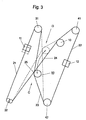
- FIG. 3 shows an adjusting device for a double-stranded cable window lifter a reduced compared to the device according to Figure 1 number of parts, wherein the Seilausschiata are coupled to a Seilauslenkvorraum 53, the extension one of the two intersecting cable strands 23, 24 by an adjustable length the respective other cable strand 24, 23 shortened by the substantially same length.
- the Seilausschvorraum 53 is in the region of the crossing point 25 of the two themselves Intersecting cable strands 23, 24 arranged and consists of a double rope pulley, which with two intersecting cable strands 23, 24 is in operative connection.
- the two themselves crossing cable strands 23, 24 are axially along the axis of rotation of the double pulley 53rd spaced apart, i.
- FIG. 4 shows a schematic representation of one of the adjusting device according to FIG. 3 corresponding adjustment, in which by adding additional Seilumlenk Anlagenen 71, 72, the crossing point 25 of the intersecting cable strands 23, 24th and the trajectory of the Seilausschieri is affected.
- the dot-dash line 15 marks the end of a power window base plate, with the example, the two guide rails the double-stranded cable window lifter are connected together and on the cable drive 10 is attached.
- the double rope pulley 54 is analogous to the adjustment device according to FIG. 3 with the two Crossing cable strands 23, 24 in operative connection, the two intersect Rope strands 23, 24 axially spaced along the axis of rotation of the double rope pulley 54 are arranged to each other.
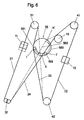
- FIG. 6 shows a schematic representation of a device for adjusting one of a Double-stranded cable window lifter moving window pane with a cable deflection device 56, which has a rotatable about its central axis 563 circular disc 560, on the two Seilausschiata 561, 562 are arranged.
- the two Seilauslenkmaschinen 561, 562 lies at least one at one of the two intersecting cable strands 23, 24 on.
- the consequent extension of the relevant cable string 23, or 24 leads to the raising or lowering of at least one of the two drivers 11, 12th
- FIG. 6 shows a first position of the front carrier 11 in solid lines, in which the diagonal cable 23 is deflected by the first Seilausschelement 561, while the second Seilausschelement 562 rests on the return cable 24 without deflecting this.
- the front driver 11 in the position shown in dashed lines becomes the rotatable circular disc 560 from the position I of the first Seilauslenkelements 561 is rotated to the position K of the first cable deflection element 561 about its central axis 563, so that the second Seilausschelement 562 deflects the return cable 24, while the first cable deflection element 561 retracts the deflection of the diagonal cable 23 until the Seilausschetti 561, 562 and the intersecting cable strands 23, 24 in the dashed lines are shown.
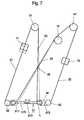
- a Seilausschvortechnische 56 with a circular disc 560 shows a translational movement of a cable deflection device be, as shown schematically in Figure 7.
- the Seilausschvoriques 57 two upper axis 570 together coupled Seilausschiata 571, 572 on each one of the two intersecting cable strands 23, 24 and rest on a displacement of the axis 570th from the position L to the position M the direction and - if only slightly - the Length of the cable strands 23 and 24 change and thus the crossing point 25 of itself shifting rope strands 23, 24 shift.
- the axis 570 is in a slot guide 573, which specifies a corresponding axial movement of the axis 570.
- FIGS. 2 to 7 relate to an open one Double-stranded cable window lifter, in which the position adjustment of one of the double-stranded Cable window lifter moved window through a corresponding counter-rotating Length change of the intersecting cable strands 23, 24 is effected.
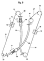
- the idea underlying the invention is also on Bowden cable windows apply as the schematic representation in Figure 8 illustrate.
- the one device 58 is designed as an active component, which is used to adjust the position the window pane moved by the double-stranded cable window lifter Fixing position can be solved and fixed again after the adjustment.
- the other device 59 for changing the length of the Bowden sheath 82 is as a passive, spring-loaded Part formed, which is a corresponding change in length due to the changing rope tension at a change in length of the first Bowden sleeve 81 by the device 58 compensates.
- the respective cable deflection elements or cable deflection devices or the device for changing the length of the Bowden sheaths are released and then the window pane is moved to the maximum upper position, ie to moved to stop on the upper edge of the window pane cutout of a motor vehicle door or alternatively in the stop position of an adjustment device.
- FIGS. 9 to 16 schematically illustrated adjusting devices coupled to each other adjusting devices on having an extension of one of the two intersecting bowden strands connect the corresponding shortening of the other Bowden strand.
- Length of at least one Bowden sheath of a Bowden strand opposite to Length changed at least one Bowden sheath of the other Bowden cord, so that for example, the one or both Bowden sheaths of the divided by the adjusting device extended on the drive side Bowdenstranges and the Bowdenhülle or both Bowden sheaths of the non-drive Bowden strand are shortened accordingly.
- the adjusting device is located in the crossing point or Bowennch 20 of the intersecting Bowden strands 26, 27, of which in the drive side Bowden cable 27 of the reversing 10 is arranged.
- FIG. 9 shows a first adjusting device 60 or 61 arranged in Bowennch 20, their different structure and function below with reference to FIGS 10 to 12 is explained.
- the adjusting device 60 or 61 is at the intersection of the intersecting Bowden strands 26, 27 arranged by the adjusting device 60 and 61 in Bowdenteilstrcarde 261, 262 and 271, 272 are divided and each a Bowden sleeve 83 to 86, which via Bowden receivers 90 with the cable guides 31, 32nd 41, 42, where the guided in the Bowden sheaths 83 to 86, a closed Loop forming rope 2 deflected and cable nipples 15, 16 with the drivers 11, 12 is connected to the non-illustrated window of the double-stranded Pick up the Bowden window lifter.
- the length of the Bowden sheath 83 to 86 each of a Bowden strand 26, 27 changed, d. H. extended or shortened.
- FIGS. 10 and 11 and 12 show two variants of the adjusting device according to FIG 9, whose structure and function with reference to these figures below is explained.
- Figure 10 shows an enlarged, schematic representation of the adjusting device 60, with the length of each Bowden sheath of a Bowden strand of the intersecting Bowden strands 26, 27 is changeable while the other bowden sheath of the same Bowdenstranges remains unchanged.
- the drive-side Bowden cable 27 is by the adjusting device 60 in the drive side Bowdenteilstrnature 271, 272 divided, of which a Bowdenteilstrang 271st a Bowden sheath 86, which is unchanged in its length, has its Bowden mount 95 is fixedly connected to the housing 600 of the adjusting device 60, while the length the other bowden sheath 85 is changeable.
- the Bowden case 85 is equipped with a Bowden mount 91 connected through an opening in the housing 600 of the adjusting device 60 is guided and at a spiral-shaped in cross section cam surface 603 a Cam 602 supported.
- the non-drive-side Bowden cable 26 is through the adjusting device 60 divided into two Bowdenteüstrnature 261, 262.
- the one non-drive side Bowdenteilstrang 261 is a Bowden with a fixed length Bowden sheath 83 provided, the Bowdenability 96 fixed to the housing 600 of the adjusting device 60 is connected.
- the other Bowdenteilstrang 262 has a Bowden with a Bowden cover 84, the Bowden 92 through an opening in the housing 600 of the adjusting device 60 is guided and on the spiral curved surface 604 a cam 601 is supported, which in a different plane to the cam 602 is arranged.
- the mutually coupled cams 601, 602 have a positive connection region 605 for receiving an adjusting tool, with which a rotation of the cam discs 601, 602 in one or the other direction of rotation is possible.
- the Bowden sheaths 83 to 86 of all Bowdenteilstrnature 261, 262; 271, 272 at their connected to the adjusting device 61 according to the figures 11 and 12 Ends provided with a Bowden 91 to 94 through openings in the housing 610 of the adjusting device 61 and engage in superimposed planes arranged cam disks 611, 612 abut.
- the cams In contrast to the cams 601, 602 according to FIG. 10, the cams have 611, 612 according to FIGS. 11 and 12 two helical spirals extending over 180 ° Curves 613, 614 and 616, 617, on each of which a Bowden recording 91 to 94 is present.
- the cams 611, 612 with one in the form-locking area 615 inserted setting tool in the direction of the registered in Figure 11 Arrows turned, so the Bowdenabilityn 91, 93 in the direction of them registered arrows pushed out of the housing 610 of the adjusting device 61, while the Bowden receivers 92, 94 in the direction of the arrows registered to them pressed by spring preload in the housing 610 of the adjusting device 61 become.
- FIG. 12 shows the change in the Bowden receptacles 91 to 94 after a corresponding one Rotation of the cams 611, 612.
- FIGS. 11 and 12 A comparison of Figures 10 to 12 illustrates that at a given slope of the Curved surfaces 603, 604 and 613, 614 and 616, 617 of the cam 601, 602 on the one hand and 611, 612 in the embodiment of the cam disks according to FIGS. 11 and 12, on the other hand, with a smaller displacement angle of the cams the same Length change of the Bowden sheaths 83 to 86 can be achieved.
- FIG. 13 shows an adjusting device 62 for coupled length adjustment Intersecting Bowden strands 26, 27 with a rack and pinion gearbox, one in one Housing 620 arranged gear 621, which with two racks 910, 940 in Intervention is at the Bowden receivers 91, 94 each of a Bowdenteilstranges 261, 272 of the intersecting Bowden strands 26, 27 are formed.
- the others Bowdenteilstrnature 271, 262 are with their Bowden recordings 95, 96 fixed to the Housing 620 connected to the rack and pinion gear.
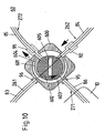
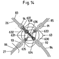
- Figure 14 shows an adjusting device 63, which is designed as a parallelogram lever mechanism is.
- the parallelogram lever mechanism consists of four via joints 632 to 635 connected lever arms 631.
- the joints 632 to 635 are with the Bowden shots 91 to 94 of the Bowden sheaths 83 to 86 of the intersecting Bowden strands 26, 27 and arranged in a housing 630 of the adjusting device 63.
- a spindle drive 636, 637, 638 the parallelogram lever mechanism is after Adjusted type of scissors jack, so that the joints 632, 634 and 633, 635 moved in opposite directions or removed from each other.
- the spindle gear has a spindle 636 which is rotated via a drive head 637 and is engaged with a spindle nut 638 which is connected to one of the joints 632 to 635 - in the illustrated embodiment with the hinge 632 - is connected, so that a rotation of the drive head 637 in one or the other direction of rotation corresponding configuration change of the parallelogram lever mechanism causes.
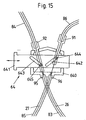
- the adjusting device 64 shown schematically in Figure 15 has a Bowenish the intersecting Bowden strands 26, 27 arranged in a housing 640 Slider 641, which in the direction of the applied to the slider 641 double arrow is adjustable.
- the slider 641 has links 642, 643 with opposite one another Inclination with respect to the direction of displacement of the slider 641, in which pins 644, 645 store, with the Bowden 91, 92 of the Bowden sheaths 84, 86 are connected in the intersecting Bowden strands 26, 27.
- the others Bowden sheaths 83, 85 of the intersecting Bowden strands 26, 27 are over their ends or Bowden receivers 95, 96 fixed to the housing 640 of the adjusting device 64th connected.
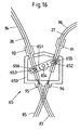
- the embodiment of the adjusting device 65 according to FIG. 16 substantially corresponds the adjusting device 64 according to Figure 15 with the proviso that the adjusting device 65 has a rotatable lever 651 disposed in a housing 650, the is rotatable about an axis 654.
- the rotatable lever 651 are compensating cams 652, 653 provided in which with the Bowden 91, 92 connected pins 655, 656 are arranged.
Landscapes
- Engineering & Computer Science (AREA)
- Mechanical Engineering (AREA)
- Window Of Vehicle (AREA)
- Power-Operated Mechanisms For Wings (AREA)
Claims (31)
- Dispositif pour régler une vitre de véhicule automobile déplacée par un lève-vitre à câble double brin, comportant deux dispositifs de renvoi de câble antérieurs, par rapport à la direction de circulation du véhicule automobile, agencés suivant la direction de déplacement de la vitre, deux dispositifs de renvoi de câble postérieurs, par rapport à la direction de circulation du véhicule automobile, agencés suivant la direction de déplacement de la vitre, un câble susceptible d'être entraíné et s'étendant en deux brins de câble en croix entre les deux dispositifs de renvoi de câble antérieurs et postérieurs suivant la direction de déplacement de la vitre et dans la zone entre les dispositifs de renvoi de câble antérieurs et les dispositifs de renvoi de câble postérieurs, dont les longueurs sont modifiables en sens opposés l'une à l'autre par des moyens pour allonger l'un des brins de câble en croix d'une longueur réglable, et pour raccourcir l'autre des deux brins de câble en croix sensiblement de la même longueur réglable, et comportant au moins un entraíneur mobile avec la vitre et par le câble suivant la direction de déplacement de la vitre,
caractérisé en ce que
le lève-vitre à câble comprend un guidage de câble ouvert au moins par tronçons, et les moyens pour modifier la longueur des brins de câble en croix (23, 24) sont agencés sous forme d'éléments de déviation de câble au niveau du guidage de câble ouvert, qui sont réalisés en étant couplés à un dispositif de déviation de câble (53 - 57) qui, lors d'un allongement de l'un des deux brins de câble en croix (23, 24) d'une longueur réglable, raccourcit l'autre brin de câble respectif (24, 23) sensiblement de la même longueur. - Dispositif selon la revendication 1, caractérisé en ce que le dispositif de déviation de câble (53 - 57) est réalisé ajustable par translation et/ou par rotation.
- Dispositif selon l'une des revendications 1 ou 2, caractérisé en ce que le dispositif de déviation de câble (53 - 56) est susceptible de pivoter d'une première position (C, E, G, I, I') dans une seconde position (D, F, H, K, K').
- Dispositif selon la revendication 3, caractérisé en ce que le dispositif de déviation de câble (51, 52) est réalisé avec au moins un dispositif de renvoi de câble antérieur et au moins un dispositif de renvoi de câble postérieur (31, 32 ; 41, 42) à titre de moyens pour modifier la position des brins de câble en croix (23, 24).
- Dispositif selon la revendication 4, caractérisé en ce que le dispositif de déviation de câble (51, 52) comprend une traverse pivotante (51) dont les extrémités sont reliés aux dispositifs de renvoi de câble (31, 32 ; 41, 42) et dont l'inclinaison est réglable au moyen d'un dispositif de positionnement (52) susceptible d'être arrêté.
- Dispositif selon la revendication 3, caractérisé en ce que le dispositif de déviation de câble (53 - 56) est agencé dans la zone du croisement (25) des deux brins de câble en croix (23, 24).
- Dispositif selon la revendication 6, caractérisé en ce que le dispositif de déviation de câble (53 - 56) est mobile en pivotement depuis la première position (C, E, G, I, I') dans une seconde position (D, F, H, K, K') sur une trajectoire approximativement circulaire.
- Dispositif selon la revendication 7, caractérisé en ce que le dispositif de déviation de câble est réalisé sous forme de poulie double (53 - 55) qui est en liaison d'action avec les deux brins de câble en croix (23, 24), les deux brins de câble en croix (23, 24) étant agencés à distance l'un de l'autre axialement suivant l'axe de rotation de la poulie double (53 - 55).
- Dispositif selon la revendication 8, caractérisé en ce que la poulie double (55) est agencée dans la zone d'un dispositif de renvoi de câble antérieur ou postérieur (31, 32 ; 41, 42).
- Dispositif selon la revendication 8, caractérisé en ce que dans l'un au moins des deux brins de câble en croix (23, 24), il est prévu au moins un dispositif de renvoi de câble supplémentaire (71, 72) qui influence la position dans l'espace du point de croisement (25) des deux brins de câble en croix (23, 24).
- Dispositif selon la revendication 7, caractérisé en ce que le dispositif de déviation de câble (56) comprend au moins deux éléments de déviation de câble (561, 562) agencés sur un disque circulaire (560) mobile en rotation autour de son axe (563), l'un au moins des éléments de déviation de câble (561, 562) prenant appui contre l'un des deux brins de câble en croix (23, 24).
- Dispositif selon la revendication 11, caractérisé en ce que le dispositif de déviation de câble (56) est mobile en pivotement par rotation du disque circulaire (560) depuis la première position (I, I') jusqu'à la seconde position (K, K').
- Dispositif selon la revendication 2, caractérisé en ce que le dispositif de déviation de câble (57) comprend deux éléments de déviation de câble (571, 572) couplés l'un à l'autre suivant un axe (570), qui font dévier respectivement l'un des deux brins de câble en croix (23, 24), et en ce que le dispositif de déviation de câble (57) est agencé avec faculté de translation suivant l'axe (570).
- Dispositif selon la revendication 13, caractérisé en ce que l'axe (570) est agencé sensiblement parallèlement à la ligne de liaison du dispositif de renvoi de câble (32) inférieur antérieur avec le dispositif de renvoi de câble (42) inférieur postérieur, vus par rapport à la direction de déplacement de la vitre.
- Dispositif selon la revendication 14, caractérisé en ce que le dispositif de déviation de câble (57) est agencé entre le dispositif de renvoi de câble (32) inférieur antérieur et le dispositif de renvoi de câble (42) inférieur postérieur.
- Dispositif selon la revendication 14, caractérisé en ce que le dispositif de déviation de câble (57) est agencé entre le dispositif de renvoi de câble (31) supérieur antérieur et le dispositif de renvoi de câble (41) supérieur postérieur.
- Dispositif pour régler une vitre de véhicule automobile déplacée par un lève-vitre à câble double brin, comportant deux dispositifs de renvoi de câble antérieurs, par rapport à la direction de circulation du véhicule automobile, agencés suivant la direction de déplacement de la vitre, deux dispositifs de renvoi de câble postérieurs, par rapport à la direction de circulation du véhicule automobile, agencés suivant la direction de déplacement de la vitre, un câble susceptible d'être entraíné et s'étendant en deux brins de câble en croix entre les deux dispositifs de renvoi de câble antérieurs et postérieurs suivant la direction de déplacement de la vitre et dans la zone entre les dispositifs de renvoi de câble antérieurs et les dispositifs de renvoi de câble postérieurs, dont les longueurs sont modifiables en sens opposés l'une à l'autre par des moyens pour allonger l'un des brins de câble en croix d'une longueur réglable, et pour raccourcir l'autre des deux brins de câble en croix sensiblement de la même longueur réglable, et comportant au moins un entraíneur mobile avec la vitre et par le câble suivant la direction de déplacement de la vitre,
caractérisé en ce que
les brins de câble en croix sont constitués par des brins de câble Bowden (26, 27) qui sont agencés au moins par tronçons dans des gaines Bowden (81 - 86), et en ce que les moyens pour allonger la longueur des brins de câble Bowden en croix (26, 27) sont constitués par des dispositifs d'ajustement (58 - 65) pour modifier la longueur des gaines Bowden (81 - 86). - Dispositif selon la revendication 17, caractérisé en ce que la longueur de la gaine Bowden (81 ou 82) entre les embouts de câble Bowden (15, 16), reliés aux entraíneurs (11, 12), de l'un des brins de câble Bowden (26 ou 27) est allongée d'une valeur prédéterminée, et la longueur de la gaine Bowden (82 ou 81) entre les embouts de câble Bowden (15, 16), reliés aux entraíneurs (11, 12), de l'autre brin de câble Bowden (27 ou 26) est raccourcie de la même valeur.
- Dispositif selon la revendication 18, caractérisé en ce que les dispositifs d'ajustement (58, 59) règlent par translation et/ou par rotation la longueur des gaines Bowden (81, 82) indépendamment l'une de l'autre et sont agencés dans la zone entre les dispositifs de renvoi de câbles (31, 32 ; 41, 42) antérieurs et postérieurs.
- Dispositif selon la revendication 18, caractérisé en ce que les dispositifs d'ajustement (60 - 65) pour modifier la longueur des gaines Bowden (83 - 86) sont couplés les uns aux autres, de sorte que lors d'un allongement de l'un des deux brins de câble Bowden en croix (26, 27) d'une longueur réglable, l'autre brin de câble Bowden respectif (27, 26) est raccourci sensiblement de la même longueur.
- Dispositif selon la revendication 20, caractérisé en ce que les dispositifs d'ajustement (60 - 65) pour modifier la longueur des gaines Bowden (83 - 86) sont agencés dans la zone de croisement (20) des brins de câble Bowden en croix (26, 27) et modifient la longueur d'au moins une gaine Bowden (85, 86) dans le brin de câble Bowden (27) côté entraínement en sens opposé à la longueur d'au moins une gaine Bowden (83, 84) dans le brin de câble Bowden (26) non côté entraínement.
- Dispositif selon la revendication 21, caractérisé par un dispositif d'ajustement (60, 61) comportant des cames (601, 602 ; 611, 612) à réglage angulaire, contre lesquelles prennent appui des logements de câble Bowden (91 - 94) des brins de câble Bowden (26, 27).
- Dispositif selon la revendication 22, caractérisé en ce que les cames (601, 602) à réglage angulaire sont agencées dans deux plans superposés et présentent des surfaces de came spiralées (603, 604) contre lesquelles prennent appui les logements de câble Bowden (91, 92), reliés aux gaines Bowden (84, 85), d'un brin partiel respectif de câble Bowden (262, 272), tandis que les gaines Bowden (83, 86) des autres brins partiels respectifs de câble Bowden (261, 271) sont reliées directement au boítier (600) du dispositif d'ajustement (60) via des logements (95, 96).
- Dispositif selon la revendication 22, caractérisé en ce que les cames (611, 612) à réglage angulaire sont agencées dans deux plans superposés et présentent des surfaces de came spiralées (613, 614, 616, 617) contre lesquelles prennent appui les logements de câble Bowden (91 - 94), reliés aux gaines Bowden (83 - 86), des brins partiels de câble Bowden (261, 262 ; 271, 272).
- Dispositif selon l'une au moins des revendications 22 à 24, caractérisé en ce que le dispositif d'ajustement (60, 61) comprend une zone de coopération de formes (605, 615) pour recevoir un outil d'ajustement.
- Dispositif selon la revendication 21, caractérisé en ce que le dispositif d'ajustement (62) comprend une roue dentée (621) qui engrène avec deux crémaillères (910, 940) qui sont reliées à des brins partiels de câble Bowden (261, 272) des deux brins de câble Bowden en croix (26, 27), qui sont agencés entre le dispositif d'ajustement (62) et les dispositifs de renvoi de câble supérieurs ou inférieurs.
- Dispositif selon la revendication 26, caractérisé en ce que les crémaillères (910, 940) sont reliées aux logements de câble Bowden (91, 94) des brins partiels de câble Bowden (261, 272) ou sont conformées sur les logements de câble Bowden (91, 94).
- Dispositif selon la revendication 21, caractérisé en ce que le dispositif d'ajustement (63) est constitué par une transmission à leviers en parallélogramme dont les articulations mutuellement opposées (632 - 635) sont reliées aux logements de câble Bowden (91 - 94) des brins de câble Bowden (26, 27).
- Dispositif selon la revendication 28, caractérisé par un dispositif de déplacement à broche (636 - 638) pour régler la distance des articulations mutuellement opposées (632 - 635) de la transmission à leviers en parallélogramme.
- Dispositif selon la revendication 21, caractérisé en ce que le dispositif d'ajustement (64) est constitué par un coulisseau (641) avec des coulisses (642, 643) inclinées en sens opposés l'une à l'autre par rapport à sa direction de translation, et en ce que deux tenons (644, 645) reliés à des logements de câble Bowden (91, 92) d'une gaine Bowden respective (84, 86) des brins de câble Bowden en croix (26, 27) sont montés dans les coulisses (642, 643).
- Dispositif selon la revendication 21, caractérisé en ce que le dispositif d'ajustement (65) comprend un levier (651) mobile en rotation autour d'un axe (654) et comprenant deux coulisses (652, 653) prévues à des extrémités opposées, dans lesquelles viennent s'engager des tenons (655, 656) reliés aux logements de câble Bowden (91, 92) de deux gaines Bowden (84, 86) des brins de câble Bowden en croix (26, 27).
Applications Claiming Priority (3)
| Application Number | Priority Date | Filing Date | Title |
|---|---|---|---|
| DE10151068A DE10151068B4 (de) | 2001-10-05 | 2001-10-05 | Vorrichtung zum Einstellen einer von einem doppelsträngigen Seilfensterheber bewegten Fensterscheibe eines Kraftfahrzeugs |
| DE10151068 | 2001-10-05 | ||
| PCT/DE2002/003847 WO2003031756A1 (fr) | 2001-10-05 | 2002-10-04 | Dispositif pour regler la position d'une vitre de vehicule automobile deplacee par un leve-vitre a cable double brin |
Publications (2)
| Publication Number | Publication Date |
|---|---|
| EP1432885A1 EP1432885A1 (fr) | 2004-06-30 |
| EP1432885B1 true EP1432885B1 (fr) | 2005-12-28 |
Family
ID=7702694
Family Applications (1)
| Application Number | Title | Priority Date | Filing Date |
|---|---|---|---|
| EP02776810A Expired - Lifetime EP1432885B1 (fr) | 2001-10-05 | 2002-10-04 | Dispositif pour regler la position d'une vitre de vehicule automobile deplacee par un leve-vitre a cable double brin |
Country Status (7)
| Country | Link |
|---|---|
| US (1) | US20050011130A1 (fr) |
| EP (1) | EP1432885B1 (fr) |
| JP (1) | JP2005504906A (fr) |
| KR (1) | KR20050033514A (fr) |
| DE (2) | DE10151068B4 (fr) |
| ES (1) | ES2253564T3 (fr) |
| WO (1) | WO2003031756A1 (fr) |
Cited By (1)
| Publication number | Priority date | Publication date | Assignee | Title |
|---|---|---|---|---|
| US9169683B2 (en) | 2012-04-10 | 2015-10-27 | Inteva Products France Sas | Window lifter comprising a holder for fastening a cable between two ends of first and second guide rails |
Families Citing this family (21)
| Publication number | Priority date | Publication date | Assignee | Title |
|---|---|---|---|---|
| FR2837459B1 (fr) * | 2002-03-19 | 2004-07-09 | Meritor Light Vehicle Sys Ltd | Procede d'assemblage de portiere |
| DE10255461B4 (de) * | 2002-11-25 | 2007-05-16 | Faurecia Innenraum Sys Gmbh | Fensterheberanordnung sowie Kraftfahrzeugtür |
| US7287804B2 (en) * | 2003-03-31 | 2007-10-30 | Ohi Seisakusho Co., Ltd. | Tension controller and opening-and-closing device for vehicle having the same |
| DE102004048924C5 (de) * | 2004-10-06 | 2014-11-27 | Küster Automotive Door Systems GmbH | Vorrichtung zum Heben und Senken einer Fensterscheibe |
| DE102005037324B4 (de) * | 2005-08-04 | 2008-06-19 | Faurecia Innenraum Systeme Gmbh | Kraftübertragungselement, Fensterheber und Kraftfahrzeugtür mit einem Fensterheber |
| US7958676B2 (en) | 2005-09-12 | 2011-06-14 | Brose Fahrzeugteile Gmbh & Co Kg, Coburg | Deflection device for an adjustment device of a motor vehicle |
| DE102007040282C9 (de) † | 2007-08-24 | 2016-03-10 | Küster Holding GmbH | Abdeckeinrichtung für den Fahrzeuginnenraum |
| US8375691B2 (en) * | 2008-06-03 | 2013-02-19 | Brose Fahrzeugteile Gmbh & Co. Kg, Coburg | Synthetic fiber rope with coupling element |
| DE202008016221U1 (de) | 2008-12-06 | 2010-04-29 | Brose Fahrzeugteile Gmbh & Co. Kommanditgesellschaft, Hallstadt | Einstellvorrichtung |
| DE102010031013A1 (de) | 2010-07-06 | 2012-01-12 | Brose Fahrzeugteile Gmbh & Co. Kommanditgesellschaft, Hallstadt | Kraftfahrzeug-Fensterheber |
| DE102012103829A1 (de) * | 2012-05-02 | 2013-11-07 | Dr. Ing. H.C. F. Porsche Aktiengesellschaft | Einrichtung zur Türscheibenführung in einem Kraftfahrzeug |
| DE102012020281A1 (de) | 2012-10-17 | 2013-05-08 | Daimler Ag | Fensterhebe-Einrichtung für ein Kraftfahrzeug |
| FR3003510B1 (fr) * | 2013-03-21 | 2015-03-27 | Inteva Products France Sas | Arret de gaine pivotant pour gaine, support, rail de guidage, ensemble, leve-vitre, procede de montage correspondants |
| DE102013007377A1 (de) | 2013-04-27 | 2014-03-20 | Daimler Ag | Fensterhebe-Einrichtung und Seitenwandung für ein Kraftfahrzeug |
| DE102016216889A1 (de) * | 2016-09-06 | 2018-03-08 | Brose Fahrzeugteile GmbH & Co. Kommanditgesellschaft, Würzburg | Antriebsvorrichtung für einen Fensterheber, mit einer schräg erstreckten Wellenachse |
| US20200071981A1 (en) * | 2018-08-31 | 2020-03-05 | Brose Fahrzeugteile Gmbh & Co. Kommanditgesellschaft, Bamberg | Window lifter assembly for adjusting a window pane |
| DE102019201793A1 (de) * | 2019-02-12 | 2020-08-13 | Brose Fahrzeugteile Se & Co. Kommanditgesellschaft, Bamberg | Kraftfahrzeugtüre |
| US11193320B2 (en) * | 2019-11-04 | 2021-12-07 | Brose Fahrzeugteile Gmbh & Co. Kommanditgesellschaft, Bamberg | Window regulator assembly |
| US11525297B2 (en) * | 2020-06-30 | 2022-12-13 | Brose Fahrzeugteile Se & Co. Kommanditgesellschaft, Bamberg | Integrated window regulator and method of making the same |
| CN112944134A (zh) * | 2021-02-05 | 2021-06-11 | 苏州长平视听设备有限公司 | 电动升降挂架 |
| CN113062674A (zh) * | 2021-04-09 | 2021-07-02 | 合肥工业大学 | 一种基于线驱机构的自动开关窗户 |
Family Cites Families (19)
| Publication number | Priority date | Publication date | Assignee | Title |
|---|---|---|---|---|
| US4001971A (en) * | 1975-09-02 | 1977-01-11 | Freedland Industries Corporation | Unit window regulator assembly |
| IT1064159B (it) * | 1976-11-10 | 1985-02-18 | Sessa T | Alzacristallo a filo di tipo perfezionato |
| DE3727153A1 (de) * | 1987-08-14 | 1989-02-23 | Kuester & Co Gmbh | Bowdenzug-fensterheber |
| DE3803118A1 (de) * | 1988-02-03 | 1989-08-17 | Porsche Ag | Fuehrungseinrichtung fuer eine in der hoehe verstellbare fensterscheibe |
| US5001867A (en) * | 1989-09-26 | 1991-03-26 | Gencorp Inc. | Door glass cassette for vehicles |
| US5490354A (en) * | 1991-09-16 | 1996-02-13 | Brose Fahrezeugteile Gmbh & Co. Kommanditgesellschaft | Cable mechanism for raising and lowering windows of motor vehicles |
| FR2728007A1 (fr) * | 1994-12-07 | 1996-06-14 | Rockwell Body & Chassis Syst | Leve-vitre du type bowden pour porte de vehicule |
| DE19544630C1 (de) * | 1995-11-30 | 1997-06-19 | Brose Fahrzeugteile | Bowdenrohr-Fensterheber mit Seillängenausgleich |
| US5964063A (en) * | 1996-07-22 | 1999-10-12 | Honda Giken Kogyo Kabushiki Kaisha | Motor-vehicle door having window winder, method of assembling the door, and window sash assembly suitable for use in the door |
| DE19654851C1 (de) * | 1996-12-30 | 1998-06-10 | Brose Fahrzeugteile | Seilfensterheber mit einer Führungsschiene |
| DE19837560C2 (de) * | 1998-08-19 | 2000-06-21 | Kiekert Ag | Doppelsträngiger Seilfensterheber |
| DE19943338B4 (de) * | 1998-09-22 | 2004-08-12 | Küster & Co GmbH | Vorrichtung zum Heben und Senken einer Fensterscheibe in einem Kraftfahrzeug |
| DE19852977C1 (de) * | 1998-11-17 | 1999-10-07 | Brose Fahrzeugteile | Vorrichtung zur Gewährleistung einer Relativbewegung zwischen Teilen eines Seilfensterhebers |
| KR100363987B1 (ko) * | 1999-06-16 | 2002-12-11 | 가부시끼가이샤 안세이 | 도어 글래스 승강 장치 |
| DE19944916A1 (de) * | 1999-09-14 | 2001-03-15 | Brose Fahrzeugteile | Seil- oder Bowdenfensterheber |
| ES2228421T3 (es) * | 2000-03-06 | 2005-04-16 | Arvinmeritor Light Vehicle Systems-France | Modulo de puerta de vehiculo con panel de puerta integrada. |
| US6430873B1 (en) * | 2000-03-08 | 2002-08-13 | Atoma International Corporation | Dual drum and rail window regulator drive system |
| US6453615B1 (en) * | 2000-10-17 | 2002-09-24 | Lear Corporation | Vehicle door subassembly, door and method for making the door |
| FR2815667B1 (fr) * | 2000-10-24 | 2003-08-01 | Meritor Light Vehicle Sys Ltd | Systeme de fixation d'un leve-vitre sur une porte sans cadre de vehicule |
-
2001
- 2001-10-05 DE DE10151068A patent/DE10151068B4/de not_active Expired - Fee Related
-
2002
- 2002-10-04 US US10/492,011 patent/US20050011130A1/en not_active Abandoned
- 2002-10-04 ES ES02776810T patent/ES2253564T3/es not_active Expired - Lifetime
- 2002-10-04 KR KR1020047004989A patent/KR20050033514A/ko not_active Application Discontinuation
- 2002-10-04 WO PCT/DE2002/003847 patent/WO2003031756A1/fr active IP Right Grant
- 2002-10-04 DE DE50205468T patent/DE50205468D1/de not_active Expired - Lifetime
- 2002-10-04 JP JP2003534712A patent/JP2005504906A/ja active Pending
- 2002-10-04 EP EP02776810A patent/EP1432885B1/fr not_active Expired - Lifetime
Cited By (1)
| Publication number | Priority date | Publication date | Assignee | Title |
|---|---|---|---|---|
| US9169683B2 (en) | 2012-04-10 | 2015-10-27 | Inteva Products France Sas | Window lifter comprising a holder for fastening a cable between two ends of first and second guide rails |
Also Published As
| Publication number | Publication date |
|---|---|
| WO2003031756A1 (fr) | 2003-04-17 |
| JP2005504906A (ja) | 2005-02-17 |
| ES2253564T3 (es) | 2006-06-01 |
| DE50205468D1 (de) | 2006-02-02 |
| DE10151068A1 (de) | 2003-04-24 |
| EP1432885A1 (fr) | 2004-06-30 |
| US20050011130A1 (en) | 2005-01-20 |
| KR20050033514A (ko) | 2005-04-12 |
| DE10151068B4 (de) | 2005-09-29 |
Similar Documents
| Publication | Publication Date | Title |
|---|---|---|
| EP1432885B1 (fr) | Dispositif pour regler la position d'une vitre de vehicule automobile deplacee par un leve-vitre a cable double brin | |
| EP0701038B1 (fr) | Lève-vitre à câble à deux boucles pour manoeuvrer des vitres à courbure sphérique | |
| DE102006025382B3 (de) | Verschlussblendenvorrichtung | |
| EP0338362B1 (fr) | Dispositif de protection solaire | |
| DE3545083C2 (fr) | ||
| DE19943338A1 (de) | Vorrichtung zum Heben und Senken einer Fensterscheibe in einem Kraftfahrzeug | |
| DE2648344C3 (de) | Beschlag für Schiebefenster, Schiebetüren o.dgl. | |
| EP1197627B1 (fr) | Commande pour portes, en particulier portes de garages | |
| EP1650068A2 (fr) | Panneau pour la construction de toit ouvrant | |
| EP0218020B1 (fr) | Toit ouvrant pour véhicules automobiles | |
| EP1531290B1 (fr) | Dispositif de sélection de vitesse | |
| DE19938253A1 (de) | Ausstellvorrichtung für einen an einem Rahmen schwenkbar angeordneten Kipp- oder Dreh-Kipp-Flügel und Dreh-Kipp-Flügel mit einer Ausstellvorrichtung | |
| DE3037851A1 (de) | Fensterheber, insbesondere fuer kraftfahrzeuge | |
| DE10239447B4 (de) | Bahnfensterheber für Fahrzeuge mit einer Grundplatte und einem Gleitelement | |
| EP0563517A1 (fr) | Entraînement combiné en poussée et en traction | |
| DE19981927C1 (de) | Seilzug-Fensterheber für Fahrzeuge | |
| DE10040597A1 (de) | Fahrzeugdach mit einem Schiebedeckel | |
| DE69507498T2 (de) | Hebe-falttor | |
| DE202009009459U1 (de) | Mitnehmer zur Anbindung einer Fensterscheibe an einen Fensterheber eines Kraftfahrzeugs | |
| DE10039842A1 (de) | Führungsschiene für eine bewegbare Fensterscheibe | |
| DE1555632A1 (de) | Scheibenfuehrung fuer in den Fensterschacht eines Fahrzeuges versenkbare Schiebefenster | |
| DE4007102C2 (fr) | ||
| DE69810380T2 (de) | Türschliesser, damit ausgerüstete Tür und Schienenfahrzeug mit mindestens einer derartigen Vorrichtung und/oder Tür | |
| EP0461104B1 (fr) | Porte basculante et coulissante | |
| DE3823293C2 (fr) |
Legal Events
| Date | Code | Title | Description |
|---|---|---|---|
| PUAI | Public reference made under article 153(3) epc to a published international application that has entered the european phase |
Free format text: ORIGINAL CODE: 0009012 |
|
| 17P | Request for examination filed |
Effective date: 20040414 |
|
| AK | Designated contracting states |
Kind code of ref document: A1 Designated state(s): AT BE BG CH CY CZ DE DK EE ES FI FR GB GR IE IT LI LU MC NL PT SE SK TR |
|
| RIN1 | Information on inventor provided before grant (corrected) |
Inventor name: KLIPPERT, UWE Inventor name: SELIGER, TILLMANN Inventor name: KRIESE, OLAF Inventor name: KAPS, ROBERT |
|
| RAP1 | Party data changed (applicant data changed or rights of an application transferred) |
Owner name: BROSE FAHRZEUGTEILE GMBH & CO. KG, COBURG |
|
| GRAP | Despatch of communication of intention to grant a patent |
Free format text: ORIGINAL CODE: EPIDOSNIGR1 |
|
| GRAS | Grant fee paid |
Free format text: ORIGINAL CODE: EPIDOSNIGR3 |
|
| GRAA | (expected) grant |
Free format text: ORIGINAL CODE: 0009210 |
|
| AK | Designated contracting states |
Kind code of ref document: B1 Designated state(s): DE ES FR GB IT |
|
| PG25 | Lapsed in a contracting state [announced via postgrant information from national office to epo] |
Ref country code: IT Free format text: LAPSE BECAUSE OF FAILURE TO SUBMIT A TRANSLATION OF THE DESCRIPTION OR TO PAY THE FEE WITHIN THE PRESCRIBED TIME-LIMIT;WARNING: LAPSES OF ITALIAN PATENTS WITH EFFECTIVE DATE BEFORE 2007 MAY HAVE OCCURRED AT ANY TIME BEFORE 2007. THE CORRECT EFFECTIVE DATE MAY BE DIFFERENT FROM THE ONE RECORDED. Effective date: 20051228 Ref country code: GB Free format text: LAPSE BECAUSE OF FAILURE TO SUBMIT A TRANSLATION OF THE DESCRIPTION OR TO PAY THE FEE WITHIN THE PRESCRIBED TIME-LIMIT Effective date: 20051228 |
|
| REG | Reference to a national code |
Ref country code: GB Ref legal event code: FG4D Free format text: NOT ENGLISH |
|
| REF | Corresponds to: |
Ref document number: 50205468 Country of ref document: DE Date of ref document: 20060202 Kind code of ref document: P |
|
| REG | Reference to a national code |
Ref country code: ES Ref legal event code: FG2A Ref document number: 2253564 Country of ref document: ES Kind code of ref document: T3 |
|
| GBV | Gb: ep patent (uk) treated as always having been void in accordance with gb section 77(7)/1977 [no translation filed] |
Effective date: 20051228 |
|
| ET | Fr: translation filed | ||
| PLBE | No opposition filed within time limit |
Free format text: ORIGINAL CODE: 0009261 |
|
| STAA | Information on the status of an ep patent application or granted ep patent |
Free format text: STATUS: NO OPPOSITION FILED WITHIN TIME LIMIT |
|
| 26N | No opposition filed |
Effective date: 20060929 |
|
| PGFP | Annual fee paid to national office [announced via postgrant information from national office to epo] |
Ref country code: ES Payment date: 20071120 Year of fee payment: 6 |
|
| REG | Reference to a national code |
Ref country code: ES Ref legal event code: FD2A Effective date: 20081006 |
|
| PG25 | Lapsed in a contracting state [announced via postgrant information from national office to epo] |
Ref country code: ES Free format text: LAPSE BECAUSE OF NON-PAYMENT OF DUE FEES Effective date: 20081006 |
|
| PGFP | Annual fee paid to national office [announced via postgrant information from national office to epo] |
Ref country code: FR Payment date: 20091029 Year of fee payment: 8 |
|
| PGFP | Annual fee paid to national office [announced via postgrant information from national office to epo] |
Ref country code: DE Payment date: 20101031 Year of fee payment: 9 |
|
| PG25 | Lapsed in a contracting state [announced via postgrant information from national office to epo] |
Ref country code: FR Free format text: LAPSE BECAUSE OF NON-PAYMENT OF DUE FEES Effective date: 20101102 |
|
| REG | Reference to a national code |
Ref country code: FR Ref legal event code: ST Effective date: 20110630 |
|
| PG25 | Lapsed in a contracting state [announced via postgrant information from national office to epo] |
Ref country code: DE Free format text: LAPSE BECAUSE OF NON-PAYMENT OF DUE FEES Effective date: 20120501 |
|
| REG | Reference to a national code |
Ref country code: DE Ref legal event code: R119 Ref document number: 50205468 Country of ref document: DE Effective date: 20120501 |