EP1432885B1 - Device for adjusting a window pane displaced by a double-stranded cable window lifter on a motor vehicle - Google Patents
Device for adjusting a window pane displaced by a double-stranded cable window lifter on a motor vehicle Download PDFInfo
- Publication number
- EP1432885B1 EP1432885B1 EP02776810A EP02776810A EP1432885B1 EP 1432885 B1 EP1432885 B1 EP 1432885B1 EP 02776810 A EP02776810 A EP 02776810A EP 02776810 A EP02776810 A EP 02776810A EP 1432885 B1 EP1432885 B1 EP 1432885B1
- Authority
- EP
- European Patent Office
- Prior art keywords
- cable
- bowden
- adjusting
- length
- crossed
- Prior art date
- Legal status (The legal status is an assumption and is not a legal conclusion. Google has not performed a legal analysis and makes no representation as to the accuracy of the status listed.)
- Expired - Lifetime
Links
Images


Classifications
-
- B—PERFORMING OPERATIONS; TRANSPORTING
- B60—VEHICLES IN GENERAL
- B60J—WINDOWS, WINDSCREENS, NON-FIXED ROOFS, DOORS, OR SIMILAR DEVICES FOR VEHICLES; REMOVABLE EXTERNAL PROTECTIVE COVERINGS SPECIALLY ADAPTED FOR VEHICLES
- B60J1/00—Windows; Windscreens; Accessories therefor
- B60J1/08—Windows; Windscreens; Accessories therefor arranged at vehicle sides
- B60J1/12—Windows; Windscreens; Accessories therefor arranged at vehicle sides adjustable
- B60J1/16—Windows; Windscreens; Accessories therefor arranged at vehicle sides adjustable slidable
- B60J1/17—Windows; Windscreens; Accessories therefor arranged at vehicle sides adjustable slidable vertically
-
- E—FIXED CONSTRUCTIONS
- E05—LOCKS; KEYS; WINDOW OR DOOR FITTINGS; SAFES
- E05F—DEVICES FOR MOVING WINGS INTO OPEN OR CLOSED POSITION; CHECKS FOR WINGS; WING FITTINGS NOT OTHERWISE PROVIDED FOR, CONCERNED WITH THE FUNCTIONING OF THE WING
- E05F11/00—Man-operated mechanisms for operating wings, including those which also operate the fastening
- E05F11/38—Man-operated mechanisms for operating wings, including those which also operate the fastening for sliding windows, e.g. vehicle windows, to be opened or closed by vertical movement
- E05F11/48—Man-operated mechanisms for operating wings, including those which also operate the fastening for sliding windows, e.g. vehicle windows, to be opened or closed by vertical movement operated by cords or chains or other flexible elongated pulling elements, e.g. tapes
- E05F11/481—Man-operated mechanisms for operating wings, including those which also operate the fastening for sliding windows, e.g. vehicle windows, to be opened or closed by vertical movement operated by cords or chains or other flexible elongated pulling elements, e.g. tapes for vehicle windows
- E05F11/483—Man-operated mechanisms for operating wings, including those which also operate the fastening for sliding windows, e.g. vehicle windows, to be opened or closed by vertical movement operated by cords or chains or other flexible elongated pulling elements, e.g. tapes for vehicle windows by cables
- E05F11/488—Man-operated mechanisms for operating wings, including those which also operate the fastening for sliding windows, e.g. vehicle windows, to be opened or closed by vertical movement operated by cords or chains or other flexible elongated pulling elements, e.g. tapes for vehicle windows by cables with two cable connections to the window glass
-
- E—FIXED CONSTRUCTIONS
- E05—LOCKS; KEYS; WINDOW OR DOOR FITTINGS; SAFES
- E05F—DEVICES FOR MOVING WINGS INTO OPEN OR CLOSED POSITION; CHECKS FOR WINGS; WING FITTINGS NOT OTHERWISE PROVIDED FOR, CONCERNED WITH THE FUNCTIONING OF THE WING
- E05F11/00—Man-operated mechanisms for operating wings, including those which also operate the fastening
- E05F11/38—Man-operated mechanisms for operating wings, including those which also operate the fastening for sliding windows, e.g. vehicle windows, to be opened or closed by vertical movement
- E05F11/48—Man-operated mechanisms for operating wings, including those which also operate the fastening for sliding windows, e.g. vehicle windows, to be opened or closed by vertical movement operated by cords or chains or other flexible elongated pulling elements, e.g. tapes
- E05F11/481—Man-operated mechanisms for operating wings, including those which also operate the fastening for sliding windows, e.g. vehicle windows, to be opened or closed by vertical movement operated by cords or chains or other flexible elongated pulling elements, e.g. tapes for vehicle windows
- E05F11/483—Man-operated mechanisms for operating wings, including those which also operate the fastening for sliding windows, e.g. vehicle windows, to be opened or closed by vertical movement operated by cords or chains or other flexible elongated pulling elements, e.g. tapes for vehicle windows by cables
- E05F11/485—Man-operated mechanisms for operating wings, including those which also operate the fastening for sliding windows, e.g. vehicle windows, to be opened or closed by vertical movement operated by cords or chains or other flexible elongated pulling elements, e.g. tapes for vehicle windows by cables with cable tensioners
-
- E—FIXED CONSTRUCTIONS
- E05—LOCKS; KEYS; WINDOW OR DOOR FITTINGS; SAFES
- E05Y—INDEXING SCHEME RELATING TO HINGES OR OTHER SUSPENSION DEVICES FOR DOORS, WINDOWS OR WINGS AND DEVICES FOR MOVING WINGS INTO OPEN OR CLOSED POSITION, CHECKS FOR WINGS AND WING FITTINGS NOT OTHERWISE PROVIDED FOR, CONCERNED WITH THE FUNCTIONING OF THE WING
- E05Y2201/00—Constructional elements; Accessories therefore
- E05Y2201/60—Suspension or transmission members; Accessories therefore
- E05Y2201/622—Suspension or transmission members elements
- E05Y2201/624—Arms
- E05Y2201/626—Levers
-
- E—FIXED CONSTRUCTIONS
- E05—LOCKS; KEYS; WINDOW OR DOOR FITTINGS; SAFES
- E05Y—INDEXING SCHEME RELATING TO HINGES OR OTHER SUSPENSION DEVICES FOR DOORS, WINDOWS OR WINGS AND DEVICES FOR MOVING WINGS INTO OPEN OR CLOSED POSITION, CHECKS FOR WINGS AND WING FITTINGS NOT OTHERWISE PROVIDED FOR, CONCERNED WITH THE FUNCTIONING OF THE WING
- E05Y2201/00—Constructional elements; Accessories therefore
- E05Y2201/60—Suspension or transmission members; Accessories therefore
- E05Y2201/622—Suspension or transmission members elements
- E05Y2201/644—Flexible elongated pulling elements; Members cooperating with flexible elongated pulling elements
- E05Y2201/654—Cables
-
- E—FIXED CONSTRUCTIONS
- E05—LOCKS; KEYS; WINDOW OR DOOR FITTINGS; SAFES
- E05Y—INDEXING SCHEME RELATING TO HINGES OR OTHER SUSPENSION DEVICES FOR DOORS, WINDOWS OR WINGS AND DEVICES FOR MOVING WINGS INTO OPEN OR CLOSED POSITION, CHECKS FOR WINGS AND WING FITTINGS NOT OTHERWISE PROVIDED FOR, CONCERNED WITH THE FUNCTIONING OF THE WING
- E05Y2201/00—Constructional elements; Accessories therefore
- E05Y2201/60—Suspension or transmission members; Accessories therefore
- E05Y2201/622—Suspension or transmission members elements
- E05Y2201/644—Flexible elongated pulling elements; Members cooperating with flexible elongated pulling elements
- E05Y2201/658—Members cooperating with flexible elongated pulling elements
- E05Y2201/668—Pulleys; Wheels
-
- E—FIXED CONSTRUCTIONS
- E05—LOCKS; KEYS; WINDOW OR DOOR FITTINGS; SAFES
- E05Y—INDEXING SCHEME RELATING TO HINGES OR OTHER SUSPENSION DEVICES FOR DOORS, WINDOWS OR WINGS AND DEVICES FOR MOVING WINGS INTO OPEN OR CLOSED POSITION, CHECKS FOR WINGS AND WING FITTINGS NOT OTHERWISE PROVIDED FOR, CONCERNED WITH THE FUNCTIONING OF THE WING
- E05Y2201/00—Constructional elements; Accessories therefore
- E05Y2201/60—Suspension or transmission members; Accessories therefore
- E05Y2201/622—Suspension or transmission members elements
- E05Y2201/696—Screw mechanisms
-
- E—FIXED CONSTRUCTIONS
- E05—LOCKS; KEYS; WINDOW OR DOOR FITTINGS; SAFES
- E05Y—INDEXING SCHEME RELATING TO HINGES OR OTHER SUSPENSION DEVICES FOR DOORS, WINDOWS OR WINGS AND DEVICES FOR MOVING WINGS INTO OPEN OR CLOSED POSITION, CHECKS FOR WINGS AND WING FITTINGS NOT OTHERWISE PROVIDED FOR, CONCERNED WITH THE FUNCTIONING OF THE WING
- E05Y2600/00—Mounting or coupling arrangements for elements provided for in this subclass
- E05Y2600/10—Adjustable or movable
- E05Y2600/12—Adjustable or movable by manual operation
-
- E—FIXED CONSTRUCTIONS
- E05—LOCKS; KEYS; WINDOW OR DOOR FITTINGS; SAFES
- E05Y—INDEXING SCHEME RELATING TO HINGES OR OTHER SUSPENSION DEVICES FOR DOORS, WINDOWS OR WINGS AND DEVICES FOR MOVING WINGS INTO OPEN OR CLOSED POSITION, CHECKS FOR WINGS AND WING FITTINGS NOT OTHERWISE PROVIDED FOR, CONCERNED WITH THE FUNCTIONING OF THE WING
- E05Y2600/00—Mounting or coupling arrangements for elements provided for in this subclass
- E05Y2600/10—Adjustable or movable
- E05Y2600/20—Adjustable or movable characterised by the movement transmission
-
- E—FIXED CONSTRUCTIONS
- E05—LOCKS; KEYS; WINDOW OR DOOR FITTINGS; SAFES
- E05Y—INDEXING SCHEME RELATING TO HINGES OR OTHER SUSPENSION DEVICES FOR DOORS, WINDOWS OR WINGS AND DEVICES FOR MOVING WINGS INTO OPEN OR CLOSED POSITION, CHECKS FOR WINGS AND WING FITTINGS NOT OTHERWISE PROVIDED FOR, CONCERNED WITH THE FUNCTIONING OF THE WING
- E05Y2900/00—Application of doors, windows, wings or fittings thereof
- E05Y2900/50—Application of doors, windows, wings or fittings thereof for vehicles
- E05Y2900/53—Application of doors, windows, wings or fittings thereof for vehicles characterised by the type of wing
- E05Y2900/55—Windows
Description
Die Erfindung bezieht sich auf eine Vorrichtung zum Einstellen einer von einem doppelsträngigen
Seilfensterheber bewegten Fensterscheibe eines Kraftfahrzeugs gemäß
dem Oberbegriff des Anspruchs 1.The invention relates to a device for adjusting one of a double-stranded
Cable window lifter moved window of a motor vehicle according to
the preamble of
Aus der DE 37 27 153 A1 ist ein Bowdenzug-Fensterheber zum Verschieben einer Fensterscheibe in einem Kraftfahrzeug bekannt, der zwei Führungsschienen aufweist, an denen die Fensterscheibe mittels je eines Mitnehmers gehalten ist, die ihrerseits an den Führungsschienen formschlüssig gleitend geführt sind und an denen der die Fensterscheibe bewegende Bowdenzug angreift, der von einer Seiltrommel mit Kurbel bewegt wird und dabei die Fensterscheibe anhebt bzw. absenkt. Um eine Schieflage der Fensterscheibe auszugleichen und sicherzustellen, dass die Fensterscheibe in ihren Endlagen bündig mit der Ober- und Unterkante des Fensterscheibenausschnitts der Kraftfahrzeugtür abschließt, ist zumindest einer der beiden Mitnehmer in eine an der Führungsschiene gleitende Mitnehmerplatte und eine die Fensterscheibe tragende Halteplatte unterteilt, zwischen denen ein an der Mitnehmerplatte angeordneter Exzenterbolzen vorgesehen ist, mit dem eine Kippung der Fensterscheibe in ihrer Ebene zur Festlegung der Abzugslinie der Fensterscheibe vorgenommen, d.h. die in Z-Richtung des Kraftfahrzeugs obere Kante der Fensterscheibe relativ zur Erstreckungsrichtung der korrespondierenden Fensterscheibendichtung justiert werden kann.From DE 37 27 153 A1 discloses a Bowden cable window lifter for moving a window pane in a motor vehicle having two guide rails, on which the window pane is held by means of a respective driver, which in turn to the Guide rails are positively slidably guided and where the window pane moving Bowden cable attacks, which moves from a cable drum with crank and thereby raises or lowers the window. To an imbalance of the windowpane balance and ensure that the windowpane is in its end positions flush with the top and bottom edges of the window pane cutout of the motor vehicle door is at least one of the two drivers in one of the guide rail sliding cam plate and a window plate supporting plate divided, between which an eccentric pin arranged on the driver plate is provided is that with a tilt of the window pane in its plane laying down the trigger line the window pane made, i. the upper in the Z direction of the motor vehicle Edge of the window pane relative to the extension direction of the corresponding window pane seal can be adjusted.
Aus dem Stand der Technik sind zur Lösung dieses Problems Seilfensterheber mit mehrteiligen Mitnehmern entsprechend der obengenannten DE 37 27 153 A1 bekannt. Ein Teil des Mitnehmers ist dabei der Seilverbindung und ein anderer Teil der Scheibenbefestigung zugeordnet. Durch die gegenseitige Verschiebung der beiden Mitnehmerteile in Z-Richtung ist es möglich, die obere Kante der Fensterscheibe in eine zur Erstreckungsrichtung der zugeordneten Fensterscheibendichtung parallele Stellung zu bringen, ohne den Spannungszustand der Seile im Fensterheber zu ändern.From the state of the art to solve this problem rope window with multi-part Mitnehmer according to the above-mentioned DE 37 27 153 A1 known. One Part of the driver is the cable connection and another part of the disc attachment assigned. By the mutual displacement of the two driver parts in the Z direction, it is possible, the upper edge of the window in a direction of extension bring the associated window pane seal parallel position without changing the state of tension of the ropes in the window regulator.
Figur 1 zeigt schematisch einen doppelsträngigen Seilfensterheber zum Anheben und
Absenken einer Fensterscheibe 1 in Z-Richtung eines Kraftfahrzeugs. Der Seilfensterheber
enthält zwei Führungsschienen 21, 22, an denen in Längsrichtung der Führungsschienen
21, 22 gleitend Mitnehmer 11, 12 zur Verbindung mit der Unterkante der Fensterscheibe
1 angeordnet sind. An den Enden der Führungsschienen 21, 22 sind Seilumlenkeinrichtungen
31, 32 bzw. 41, 42 befestigt, an denen ein Fensterheberseil 2 umgelenkt
wird. In der schematischen Darstellung eines doppelsträngigen Seilfensterhebers
gemäß Figur 1 sind zwei in Bezug auf die Fahrtrichtung des Kraftfahrzeugs (X-Richtung)
vordere Seilumlenkeinrichtungen 31, 32 sowie zwei in Bezug auf die Fahrtrichtung des
Kraftfahrzeugs hintere Seilumlenkeinrichtungen 41, 42 an den Enden der Führungsschienen
21, 22 vorgesehen, die in dieser Terminologie jeweils benachbart zur A-Säule
bzw. B-Säule des Kraftfahrzeugs angeordnet sind. Die Seilumlenkeinrichtungen 31, 32
bzw. 41, 42 sind in der schematischen Darstellung gemäß Figur 1 als Seilrollen ausgeführt,
sie können aber auch als Umlenk-Gleitstücke ausgeführt werden.Figure 1 shows schematically a double-stranded cable window lifter for lifting and
Lowering a
Die für die Kraftübertragung notwendige geschlossene Seilschlaufe des Fensterheberseils
2 erstreckt sich somit in den Seilabschnitten 21, 22 zwischen den Umlenkeinrichtungen
31, 32 bzw. 41, 42 entlang der Führungsschienen 21, 22, wobei das Seil 2 an
zwei Stellen mit den Mitnehmern 11, 12 verbunden ist und wird über sich kreuzende Seilstränge
23, 24, aus denen sich ein Kreuzungspunkt 25 ergibt, zur jeweils anderen Führungsschiene
21, 22, bzw. zu einer Antriebseinheit 10 geleitet. Die Antriebseinheit 9 enthält
eine Seiltrommel, wobei mehrere Umschlingungen des Seils 2 auf der Seiltrommel
und gegebenenfalls eine formschlüssige Verbindung zwischen dem Seil 2 und der Seiltrommel
über eine Seilnippeleinhängung die Kraftübertragung auf das Seil 2 gewährleisten.
Die Antriebskraft wird entweder von einem Elektromotor oder von einer Kurbel erzeugt
und in ein Getriebe eingeleitet, das die Seiltrommel enthält.The necessary for the power transmission closed loop of the
Alternativ zu dem in Figur 1 dargestellten offenen doppelsträngigen Seilfensterhebersystem
können die sich kreuzenden Seilstränge 23, 24 des Seils 2 aus Bowdenhüllen wie
beim doppelsträngigen Seilfensterheber der DE 37 27 153 A1 bestehen. As an alternative to the open double-stranded cable window lifter system shown in FIG
can the intersecting
Eine Justage der Z-Position der Fensterscheibe 1 erfolgt bei diesem Seilfensterheber
durch mindestens einen zweiteiligen Mitnehmer 11, 12, von denen ein Teil der Verbindung
mit dem Seil 2 und den Führungsschienen 21, 22 und das andere Teil der Verbindung
mit der Fensterscheibe 1 zugeordnet ist. Durch eine gegenseitige Positionsverschiebung
der beiden Mitnehmerteile in Z-Richtung ist eine Parallelitätseinstellung der
Fensterscheibe 1 möglich. Da die Mitnehmer 11, 12 jedoch schwer zugänglich sind, bzw.
vor einer Einstellung einer Abzugslinie der Fensterscheibe 1 in eine für die Einstellung
günstige Position verfahren werden müssen, ist das Einstellen der Abzugslinie der Fensterscheibe
1 bei bekannten doppelsträngigen Seilfensterhebern umständlich und zeitaufwendig.
Darüber hinaus ist die zweigeteilte Konstruktion der Mitnehmer sehr aufwendig,
wobei die Mitnehmer wegen der zweiteiligen Ausführung beispielsweise aus Metall-Druckguss
gefertigt werden und daher sehr toleranzanfällig und teuer sind. Weiterhin
dürfen derartige Mitnehmer nur geringe Fertigungstoleranzen aufweisen, so dass deren
Herstellung insgesamt betrachtet vergleichsweise kostenintensiv ist.An adjustment of the Z position of the
Aus der DE 198 37 560 C2 ist ein doppeisträngiger Seilfensterheber für eine Kraftfahrzeugtür mit zwei heb- und senkbaren Mitnehmern bekannt, an denen eine Fensterscheibe befestigt ist. Die Mitnehmer sind über eine geschlossene Seilschleife mit einem reversierend arbeitenden Antrieb verbunden, wobei die geschlossene Seilschleife zwei sich kreuzende Seilstränge mit einem Seilzug und einem Verbindungsseilzug ausbildet. Im Verbindungsseilzug ist eine mit einem Exzenter versehene Federspannvorrichtung vorgesehen, die gegen den Verbindungsseilzug federunterstützt angestellt ist. Bei in Bezug auf die Fensteraussparung im Fensterrahmen schräg angeordneter Fensterscheibe schlägt die Fensterscheibe beim Heben einseitig am Fensterrahmen in einem Berührungspunkt oberhalb eines der beiden Mitnehmer an. Anschließend gibt der Seilzug gegen den Widerstand der Federspannvorrichtung nach und verschiebt den anderen Mitnehmer, so dass die Fensterscheibe gegen den Fensterrahmen geschwenkt und dadurch ausgerichtet wird. Nach der Ausrichtung der Fensterscheibe wird die Federspannvorrichtung in der entsprechenden Stellung zur Justage der Fensterscheibe fixiert.From DE 198 37 560 C2 is a double-stranded cable window lifter for a motor vehicle door with two raisable and lowerable carriers known to which a window is attached. The drivers are reversing via a closed cable loop with one working drive connected, the closed loop rope two Intersecting cable strands with a cable and a connecting cable trains. in the Verbindungsseilzug is provided with an eccentric spring tensioning device, which is employed against the connecting cable spring assisted. In relation to on the window recess in the window frame obliquely arranged window pane beats the window when lifting on one side of the window frame in a touch point above one of the two drivers. Then the cable is against the resistance of the spring tensioning device and moves the other driver, so that the window pane is pivoted against the window frame and thereby is aligned. After aligning the window pane, the spring tensioning device fixed in the appropriate position for adjusting the window pane.
Aufgabe der vorliegenden Erfindung ist es, eine Vorrichtung zum Einstellen einer von
einem doppelsträngigen Seilfensterheber bewegten Fensterscheibe eines Kraftfahrzeugs
gemäß dem Oberbegriff des Anspruchs 1 anzugeben, die einfach aufgebaut ist und eine
einfache, sichere und äußerst genaue Einstellung der Lage der Fensterscheibe eines
Kraftfahrzeugs gewährleistet. The object of the present invention is to provide a device for adjusting one of
a double-stranded cable window lifter moving window of a motor vehicle
specify according to the preamble of
Diese Aufgabe wird durch die Merkmale der Patentansprüche 1 und 15 gelöst.This object is solved by the features of
Die erfindungsgemäße Lösung ermöglicht ein sehr einfaches und äußerst genaues Einstellen der Lage einer von einem doppelsträngigen Seilfensterheber bewegten Fensterscheibe eines Kraftfahrzeugs in der Fensterscheibenebene mit geringem Zeitaufwand und einfach aufgebauten und zu handhabenden Einstellungsmitteln. Die erfindungsgemäße Vorrichtung eignet sich sowohl für offene doppelsträngige Seilfensterhebersysteme als auch für Bowden-Fensterhebersysteme.The solution according to the invention enables a very simple and extremely accurate setting the location of a window pane moved by a double-stranded cable window lifter a motor vehicle in the window pane level with little time and simply built-up and handled adjustment means. The inventive Device is suitable for both open double-stranded cable window systems as well as for Bowden window regulator systems.
Die erfindungsgemäße Lösung geht von der Überlegung aus, daß in einem offenen Seilfensterhebersystem die Seilabschnitte in ihrer Spannung direkt beeinflußbar sind, so daß durch bewegliche Seilrollen die Weglängen der diagonal verlaufenden Seilabschnitte, d.h. der beiden sich kreuzenden Seilstränge verändert werden können. Auf diese Weise kann mit geringem Herstellungs- und Montageaufwand eine optimale Einstellung der Lage der Fensterscheibe vorgenommen werden, ohne daß eine Zweiteilung eines oder beider Mitnehmer erforderlich ist.The solution according to the invention is based on the consideration that in an open cable window system the cable sections are directly influenced in their voltage, so that by moving pulleys the path lengths of the diagonally extending cable sections, i.e. the two intersecting cable strands can be changed. In this way can with low manufacturing and assembly costs optimal adjustment of Position of the window can be made without a division of one or both drivers are required.
Die erfindungsgemäße Lösung läßt verschiedene Ausführungsformen sowohl an offenen Seilfensterhebersystemen als auch an Bowden-Fensterhebersystemen zu, wobei allen Ausführungsformen die gegenläufige Längenänderung der sich kreuzenden Seilstränge gemeinsam ist, die jedoch mit unterschiedlichen Mitteln realisiert wird.The solution according to the invention makes various embodiments both open Cable window systems as well as to Bowden window systems to, where all Embodiments the opposite change in length of the intersecting cable strands is common, but which is realized by different means.
In einer ersten Ausführungsform weist der Seilfensterheber eine mindestens abschnittsweise offene Seilführung auf und die Mittel zur Veränderung der Länge der sich kreuzenden Seilstränge sind an der offenen Seilführung als Seilauslenkelemente angeordnet, die zu einer Seilauslenkvorrichtung gekoppelt ausgebildet sind, die bei Verlängerung eines der beiden kreuzenden Seilstränge um eine einstellbare Länge den jeweils anderen Seilstrang um die im wesentlichen gleiche Länge verkürzt, so dass beispielsweise zur Veränderung der Position des der A-Säule des Kraftfahrzeugs benachbarten Mitnehmers das Diagonalseil, d.h. der eine Seilstrang, um einen Betrag verlängert und der Rückholstrang, d.h. der andere Seilstrang der sich kreuzenden Seilstränge, um dasselbe Mass verkürzt wird. Dabei hält die Koppelung der Seilauslenkelemente zu einer Seilauslenkvorrichtung die Teilezahl und die Komplexität der Vorrichtung möglichst gering. In a first embodiment, the cable window lifter has an at least sections open rope guide on and the means of changing the length of the intersecting Cable strands are arranged on the open cable guide as Seilauslenkelemente, which are formed coupled to a Seilauslenkvorrichtung, the extension one of the two crossing cable strands with an adjustable length each other Cable cord shortened by the substantially same length, so that, for example, the Change in the position of the A-pillar of the motor vehicle adjacent driver the diagonal rope, i. the one strand of rope, extended by an amount and the return strand, i.e. the other rope strand of the crossing rope strands, to the same measure is shortened. The coupling of Seilauslenkelemente holds to a Seilauslenkvorrichtung the number of parts and the complexity of the device as low as possible.
Die Seilauslenkvorrichtung zur gegenläufigen Veränderung der Länge der sich kreuzenden Seilstränge, d.h. der Verlängerung des einen Seilstranges und der Verkürzung des anderen Seilstranges um die im wesentlichen gleiche einstellbare Länge kann translatorisch und/oder rotatorisch justierbar ausgebildet sein. Dadurch kann eine beliebige Bogenform oder auch eine abschnittsweise rein translatorische oder rotatörische Auslenkung realisiert werden.The Seilauslenkvorrichtung for opposing change in the length of the intersecting Rope strands, i. the extension of the one strand of rope and the shortening of the rope other rope strand around the substantially same adjustable length can be translational and / or rotationally adjustable. This can be any arc shape or a sectionally purely translatory or rotatörische deflection will be realized.
In einer ersten Variante der Erfindung ist die Seilauslenkvorrichtung mit mindestens einer vorderen und hinteren Seilumlenkeinrichtung als Mittel zur Veränderung der Lage der sich kreuzenden Seilstränge ausgebildet und weist eine schwenkbare Traverse auf, deren Enden mit den Seilumlenkeinrichtungen verbunden sind und deren Neigung mit einer arretierbaren Stelleinrichtung einstellbar ist.In a first variant of the invention, the cable deflection device is provided with at least one front and rear rope deflection device as a means of changing the position of the formed crossing rope strands and has a pivotable crosshead, whose Ends are connected to the Seilumlenkeinrichtungen and their inclination with a lockable adjusting device is adjustable.
Bei dieser gekoppelten Justierung der Mitnehmer und damit der Fensterscheibe sind keine zusätzlichen, auf das Seil einwirkenden Spannmittel erforderlich, da die Justiereinrichtung unmittelbar an der Seilumlenkeinrichtung angreiftIn this coupled adjustment of the driver and thus the window pane are no additional, acting on the rope clamping means required because the adjusting device acts directly on the Seilumlenkeinrichtung
Die Seilauslenkvorrichtung ist in einer weiteren Variante der Erfindung im Bereich der Kreuzung der beiden sich kreuzenden Seilstränge angeordnet und ermöglicht daher mit einer einzigen Handhabung eine exakte Einstellung der Fensterscheibenausrichtung.The Seilauslenkvorrichtung is in a further variant of the invention in the field of Crossing the two intersecting cable strands arranged and therefore allows with a single handling an exact adjustment of the window pane alignment.
Vorzugsweise ist die Seilauslenkvorrichtung insbesondere auf einer annähernd kreisförmigen Bahn von einer ersten Position in eine zweite Position verschwenkbar.Preferably, the Seilauslenkvorrichtung is particularly on an approximately circular Track pivotable from a first position to a second position.
In dieser Ausführungsform werden das Diagonal- und Rückholseil beispielsweise über auf einer gemeinsamen Achse laufende Doppelseilrollen geführt, wobei die Bahn, auf der die Doppelseilrollenachse geführt und fixiert wird, so zu wählen ist, dass bei einer Verkürzung des einen Seilstranges der sich kreuzenden Seilstränge der andere Seilstrang um das gleiche Mass verlängert wird. Somit spannt die Doppelseilrolle in den beiden Endpositionen eines der beiden Mitnehmer den einen Seilabschnitt voll vor und beläßt den anderen Seilabschnitt gerade in gestreckter Position.In this embodiment, the diagonal and Rückholseil example over on a common axis running double rope pulleys, wherein the web, on the the double pulley axis is guided and fixed so it is to be chosen that at a shortening one rope strand of intersecting rope strands the other rope strand is extended by the same measure. Thus, the double pulley tensioned in the two End positions of one of the two drivers fully one rope section before and leaves the other rope section straight in the extended position.
Die sich kreuzenden Seilstränge sind axial entlang der Drehachse der Doppelseilrolle beabstandet zueinander angeordnet. Dabei kann die Doppelseilrolle im Bereich einer vorderen oder hinteren Seilumlenkeinrichtung angeordnet werden. The crossing cable strands are axially along the axis of rotation of the double rope pulley spaced apart from each other. In this case, the double rope pulley in the area of front or rear Seilumlenkeinrichtung be arranged.
Um eine größere Anpassung an die Einbauverhältnisse in einer Kraftfahrzeugtür zu erreichen, können die Bahnen, auf denen sich die Doppelseilrolle bewegt, in Form und Lage durch weitere Seilumlenkeinrichtungen verändert werden, die die sich kreuzenden Seilstränge des Fensterheberseils verändern. Dementsprechend besteht ein weiteres Merkmal der erfindungsgemäßen Lösung darin, dass in mindestens einem der beiden sich kreuzenden Seilstränge mindestens eine weitere Seilumlenkeinrichtung angeordnet ist, die die räumliche Lage des Kreuzungspunktes der beiden sich kreuzenden Seilstränge beeinflußt.In order to achieve a greater adaptation to the installation conditions in a motor vehicle door, The tracks on which the double pulley moves can be in shape and position be changed by other Seilumlenkeinrichtungen that the intersecting Change the cable strands of the window lifter rope. Accordingly, there is another Feature of the inventive solution is that in at least one of the two at least one further Seilumlenkeinrichtung arranged crossing ropes is the spatial location of the crossing point of the two intersecting cable strands affected.
Das Verschwenken der Seilauslenkvorrichtung von einer ersten Position in eine zweite Position kann alternativ dadurch vorgenommen werden, daß die Seilauslenkvorrichtung mindestens zwei auf einer um ihre Achse drehbaren Kreisscheibe angeordnete Seilführungselemente umfaßt, von denen mindestens eines an einem der beiden sich kreuzenden Seilstränge anliegt. Durch Rotation der Kreisscheibe ist die Seilauslenkvorrichtung von der ersten Position in die zweite Position verschwenkbar.The pivoting of the Seilauslenkvorrichtung from a first position to a second Position can alternatively be made by the Seilauslenkvorrichtung at least two arranged on a circular disk rotatable about its axis cable guide elements at least one of which intersects at one of the two Ropes rests. By rotation of the circular disk is the Seilauslenkvorrichtung pivotable from the first position to the second position.
Eine weitere Ausführungsform besteht darin, daß die Seilauslenkvorrichtung zwei entlang einer Achse miteinander gekoppelte Seilauslenkelemente umfaßt, die jeweils einen der beiden sich kreuzenden Seilstränge auslenken, wobei die Seilauslenkvorrichtung entlang der Achse verschiebbar angeordnet ist.A further embodiment is that the Seilauslenkvorrichtung two along An axle coupled to each other comprises Seilauslenkelemente, each one of deflecting two intersecting rope strands, the Seilauslenkvorrichtung along the axis is arranged displaceably.
In dieser Ausführungsform einer Seilauslenkvorrichtung wird die Achse, entlang der die Auslenkvorrichtung verschiebbar angeordnet ist, im wesentlichen parallel zur Verbindungslinie der unteren vorderen Seilumlenkeinrichtung mit der unteren hinteren Seilumlenkeinrichtung verschoben. Diese Anordnung kann an beliebiger Stelle zwischen der unteren vorderen und der unteren hinteren Seilumlenkeinrichtung oder zwischen der oberen vorderen und oberen hinteren Seilumlenkeinrichtung erfolgen.In this embodiment of a cable deflection device, the axis along which the Deflection device is arranged displaceably, substantially parallel to the connecting line the lower front Seilumlenkeinrichtung with the lower rear Seilumlenkeinrichtung postponed. This arrangement can be placed anywhere between the lower front and lower rear cable deflection or between the upper Front and upper rear Seilumlenkeinrichtung done.
Weiterhin kann die Seilumlenkeinrichtung in Doppelfunktion sowohl einen Seillängenausgleich bewirken als auch einer Nachführung der Seilspannung dienen. Für einen Bowdenzug-Fensterheber wird die erfindungsgemäße Lösung dadurch realisiert, dass die sich kreuzenden Seilstränge als Bowdenstränge ausgebildet und zumindest abschnittsweise in Bowdenhüllen angeordnet und die Mittel zur Veränderung der Länge der sich kreuzenden Bowdenstränge aus Justiereinrichtungen zur Veränderung der Länge der Bowdenhüllen bestehen.Furthermore, the Seilumlenkeinrichtung in double function both a rope length compensation cause as well as a tracking of the rope tension serve. For a Bowden cable window lifter solution according to the invention is realized thereby, that the intersecting cable strands formed as Bowden strands and at least arranged in sections in Bowden sheaths and the means for changing the Length of intersecting Bowden strands of adjusting devices for change consist of the length of the Bowden sheaths.
Durch die Veränderung der Länge der sich kreuzenden Bowdenstränge durch eine Veränderung der Länge der Bowdenhüllen kann aus den sich daraus ergebenden unterschiedlichen Seilabschnittslängen eine Ausrichtung der Fensterscheibe in Bezug auf den Fensterrahmen mit einfachen Mitteln durchgeführt werden.By changing the length of the intersecting Bowden strands by a change The length of the bowden sheaths may be different from the resulting ones Cable section lengths an orientation of the window pane with respect to the Window frames can be done with simple means.
Die Justage der Fensterscheibe über eine Veränderung der Längen der Bowdenhüllen kann sowohl über unabhängig voneinander in den sich kreuzenden Bowdensträngen angeordnete Justiereinrichtungen erfolgen, mit denen die Länge der Bowdenhüllen zwischen den mit den Mitnehmern verbundenen Bowdenzugnippeln des einen Bowdenstranges um ein vorgebbares Maß verlängert und die Länge der Bowdenhülle zwischen den mit den Mitnehmern verbundenen Bowdenzugnippeln des anderen Bowdenstranges um ein gleiches Maß verkürzt wird.The adjustment of the window pane via a change in the lengths of the Bowden sheaths Can be both independently in the intersecting Bowden strands arranged adjusting devices take place, with which the length of the Bowden covers between the Bowdenzugnippeln associated with the drivers of a Bowden strand lengthened by a predetermined amount and the length of the bowden sheath between the Bowdenzugnippeln of the other Bowdenstrang connected to the drivers is shortened by an equal amount.
Alternativ kann die Justage der Fensterscheibe über eine Veränderung der Längen der Bowdenhüllen durch miteinander gekoppelte Justiereinrichtungen erfolgen, so dass bei einer Verlängerung eines der beiden sich kreuzenden Bowdenstränge um eine einstellbare Länge der jeweils andere Bowdenstrang um die im Wesentlichen gleiche Länge verkürzt wird.Alternatively, the adjustment of the window pane via a change in the lengths of the Bowden sheaths done by coupled with each other adjusting devices, so that at an extension of one of the two intersecting Bowden strands to an adjustable Length of the other Bowden strand to the substantially same length is shortened.
Bei voneinander unabhängigen Justiereinrichtungen kann die Länge der Bowdenhüllen unabhängig voneinander translatorisch und/oder rotatorisch verändert werden, wobei die Justiereinrichtungen im Bereich zwischen den vorderen und hinteren Seilumlenkeinrichtungen angeordnet sind.For independent adjustment devices, the length of the Bowden sheaths be changed independently translational and / or rotational, wherein the Adjustment devices in the area between the front and rear Seilumlenkeinrichtungen are arranged.
Miteinander gekoppelte Justiereinrichtungen können unter Beibehaltung desselben Funktionsprinzips auf mannigfaltige Weise ausgebildet werden.Coupled with each other adjusting devices while maintaining the same principle of operation be formed in a variety of ways.
In einer ersten Ausführungsform besteht die Justiereinrichtung aus winkelverstellbaren Kurvenscheiben, an denen Bowdenaufnahmen der Bowdenstränge anliegen.In a first embodiment, the adjusting device consists of angle-adjustable Cams on which Bowden shafts of the Bowden strands lie.
Die winkelverstellbaren Kurvenscheiben sind in zwei übereinander liegenden Ebenen angeordnet und weisen spiralförmige Kurvenflächen auf, an denen die mit Bowdenhüllen verbundenen Bowdenaufnahmen jeweils eines Bowdenteilstranges, während die Bowdenhüllen der jeweils anderen Bowdenteilstränge über Aufnahmen unmittelbar mit dem Gehäuse der Justiereinrichtung verbunden sind.The angle-adjustable cams are in two superimposed planes arranged and have spiral curve surfaces on which the with Bowden sheaths connected Bowden shots each of a Bowdenteilstranges, while the Bowden sheaths the other Bowdenteilstränge on recordings directly with the Housing the adjusting device are connected.
Alternativ sind die winkelverstellbaren Kurvenscheiben in zwei übereinander liegenden Ebenen angeordnet und weisen spiralförmige Kurvenflächen auf, an denen die mit Bowdenhüllen verbundenen Bowdenaufnahmen aller Bowdenteilstränge anliegen.Alternatively, the angle-adjustable cams are in two superimposed Plane arranged and have spiral curve surfaces on which the with Bowden sheaths connected Bowdenaufnahmen all Bowdenteilstränge abut.
Zur einfachen Justage des Fensterhebers weist die Justiereinrichtung einen Formschlussbereich zur Aufnahme eines Justierwerkzeuges auf.For easy adjustment of the window, the adjusting device has a positive connection region for receiving an adjusting tool.
In einer zweiten Ausführungsform weist die Justiereinrichtung ein Zahnrad auf, das mit zwei Zahnstangen kämmt, die mit Bowdenteilsträngen der beiden sich kreuzenden Bowdenstränge verbunden sind, die zwischen der Justiereinrichtung und den oberen oder unteren Seilumlenkeinrichtungen angeordnet sind.In a second embodiment, the adjusting device has a gear that with two racks mesh, the Bowdenteilsträngen of the two intersecting Bowden strands connected between the adjusting device and the upper or lower Seilumlenkeinrichtungen are arranged.
Die Zahnstangen sind vorzugsweise mit den Bowdenaufnahmen der Bowdenteilstränge verbunden oder an den Bowdenaufnahmen angeformt.The racks are preferably with the Bowden shots Bowdenteilstränge connected or formed on the Bowdenaufnahmen.
In einer dritten Ausführungsform besteht die Justiereinrichtung aus einem Parallelogramm-Hebelgetriebe, dessen einander gegenüber liegende Gelenke mit den Bowdenaufnahmen der Bowdenstränge verbunden sind. Eine Spindelverstellung dient zur Einstellung des Abstandes der einander gegenüber liegenden Gelenke des Parallelogramm-Hebelgetriebes.In a third embodiment, the adjusting device consists of a parallelogram lever mechanism, its opposing joints with the Bowdenaufnahmen the Bowden strands are connected. A spindle adjustment is used for adjustment the distance of the opposing joints of the parallelogram lever mechanism.
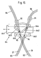
In einer vierten Ausführungsform besteht die Justiereinrichtung aus einem Schieber mit Kulissen mit in Bezug auf dessen Verschieberichtung einander entgegengesetzter Neigung und zwei mit Bowdenaufnahmen jeweils einer Bowdenhülle der sich kreuzenden Bowdenstränge verbundene Zapfen sind in den Kulissen gelagert sind.In a fourth embodiment, the adjusting device consists of a slide with Scenes with respect to the direction of displacement opposite each other and two with bowden shots each of a bowden sheath of intersecting Bowden cord connected pins are stored in the wings.
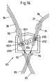
In einer fünften Ausführungsform weist die Justiereinrichtung einen um eine Achse drehbaren Hebel auf, der zwei an entgegengesetzten Enden vorgesehene Kulissen enthält, in die mit den Bowdenaufnahmen zweier Bowdenhüllen der sich kreuzenden Bowdenstränge verbundene Zapfen eingreifen. In a fifth embodiment, the adjusting device has a rotatable about an axis Lever on which contains two provided at opposite ends scenes, in with the Bowden shots of two Bowden sheaths of the intersecting Bowden strands engaging connected pins.
Bei einer Kombination eines offenen doppelsträngigen Seilfensterhebersystems mit Bowdenhüllen in einzelnen Seilabschnitten kann die erfindungsgemäße Lösung in der Weise eingesetzt werden, dass der Seilfensterheber eine mindestens abschnittsweise offene Seilführung aufweist und die Mittel zur Veränderung der Länge der sich kreuzenden Seilstränge an der offenen Seilführung als Seilauslenkelemente angeordnet sind.In a combination of an open double-stranded cable window system with Bowden sheaths in individual cable sections, the solution according to the invention in the Be used manner that the cable window lifter at least partially has open cable guide and the means for changing the length of the intersecting Cable strands are arranged on the open cable guide as Seilauslenkelemente.
Anhand von in der Zeichnung dargestellten Ausführungsbeispielen soll der der Erfindung zugrunde liegende Gedanke näher erläutert werden. Es zeigen:
- Fig. 1
- eine schematische Darstellung eines doppelsträngigen Seilfensterhebers nach dem Stand der Technik;
- Fig. 2
- eine schematische Darstellung eines doppelsträngigen Seilfensterhebers mit an einer schwenkbaren und arretierbaren Traverse als Seilauslenkvorrichtung befestigten Seilumlenkrollen;
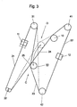
- Fig. 3
- eine schematische Darstellung eines doppelsträngigen Seilfensterhebers mit auf einer Seilauslenkvorrichtung angeordneten und als Doppelseilrollen ausgebildeten Auslenkvorrichtungen;
- Fig. 4
- eine schematische Darstellung wie in Figur 3 mit weiteren Seilumlenkeinrichtungen zur Beeinflussung der räumlichen Lage des Kreuzungspunktes der beiden sich kreuzenden Seilstränge;
- Fig. 5
- eine schematische Darstellung einer Seilauslenkvorrichtung wie in Figur 3 mit im Bereich der vorderen Seilumlenkeinrichtung angeordneter Doppelseilrolle;
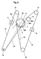
- Fig. 6
- eine schematische Darstellung eines doppelsträngigen Seilfensterhebers mit einer Seilauslenkvorrichtung mit zwei auf einer um ihre Achse drehbaren Kreisscheibe angeordneten Seilführungselementen;
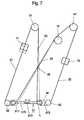
- Fig. 7
- eine schematische Darstellung eines doppelsträngigen Seilfensterhebers mit einer Seilauslenkvorrichtung mit zwei entlang einer Achse miteinander gekoppelten Seilauslenkelementen;
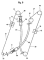
- Fig. 8
- eine schematische Darstellung eines doppelsträngigen Seilfensterhebers mit abschnittsweise in Bowdenhüllen angeordneten sich kreuzenden Seilsträngen und Vorrichtungen zur Veränderung der Länge der Bowdenhüllen;
- Fig. 9
- eine schematische Darstellung eines doppelsträngigen Seilfensterhebers vom Typ eines geschlossenen Systems unter Verwendung von Bowden und einer gekoppelten Justage der sich kreuzenden Bowdenstränge;
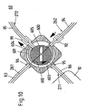
- Fig. 10
- eine vergrößerte Darstellung der Justiereinrichtung gemäß Figur 9 mit in zwei übereinander liegenden Ebenen angeordneten Kurvenscheiben und zwei Bowdenaufnahmen;
- Fig. 11 u. 12
- eine vergrößerte Darstellung der Justiereinrichtung gemäß Figur 9 mit zwei in übereinander liegenden Ebenen angeordneten Kurvenscheiben und vier Bowdenaufnahmen;
- Fig. 13
- eine vergrößerte, schematische Darstellung einer Justiereinrichtung mit einem Zahnstangengetriebe;
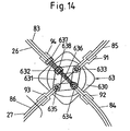
- Fig. 14
- eine vergrößerte, schematische Darstellung einer Justiereinrichtung mit einem Parallelogramm-Hebelgetriebe;
- Fig. 15
- eine vergrößerte, schematische Darstellung einer Justiereinrichtung mit einem Schieber mit verschiebbaren Kulissen entgegengesetzter Neigung und
- Fig. 16
- eine vergrößerte, schematische Darstellung einer Justiereinrichtung mit einem drehbaren Hebel mit Ausgleichskulissen zur Aufnahme von Zapfen zweier Bowdenaufnahmen.
- Fig. 1
- a schematic representation of a double-stranded cable window lifter according to the prior art;
- Fig. 2
- a schematic representation of a double-stranded cable window lifter with attached to a pivotable and lockable Traverse as Seilauslenkvorrichtung Seilumlenkrollen;
- Fig. 3
- a schematic representation of a double-stranded cable window lifter with arranged on a Seilauslenkvorrichtung and designed as a double rope pulleys deflection devices;
- Fig. 4
- a schematic representation as in Figure 3 with further Seilumlenkeinrichtungen for influencing the spatial position of the intersection of the two intersecting cable strands;
- Fig. 5
- a schematic representation of a Seilauslenkvorrichtung as in Figure 3 with arranged in the region of the front Seilumlenkeinrichtung double rope pulley;
- Fig. 6
- a schematic representation of a double-stranded cable window lifter with a Seilauslenkvorrichtung with two arranged on a rotatable about its axis circular disk guide elements;
- Fig. 7
- a schematic representation of a double-stranded cable window lifter with a Seilauslenkvorrichtung with two along an axis coupled to each Seilauslenkelementen;
- Fig. 8
- a schematic representation of a double-stranded cable window lifter with partially arranged in Bowden sheaths crossing cable strands and devices for changing the length of the Bowden sheaths;
- Fig. 9
- a schematic representation of a double-stranded cable window lifter of the closed-system type using Bowden and a coupled adjustment of the intersecting Bowdenstränge;
- Fig. 10
- an enlarged view of the adjusting device according to Figure 9 arranged in two superposed planes cams and two Bowdenaufnahmen;
- Fig. 11 u. 12
- an enlarged view of the adjusting device according to Figure 9 with two arranged in superimposed planes cams and four Bowden shots;
- Fig. 13
- an enlarged, schematic representation of an adjusting device with a rack gear;
- Fig. 14
- an enlarged, schematic representation of an adjusting device with a parallelogram lever mechanism;
- Fig. 15
- an enlarged, schematic representation of an adjusting device with a slider with sliding scenes opposite slope and
- Fig. 16
- an enlarged, schematic representation of an adjusting device with a rotatable lever with compensating gates for receiving pins of two Bowden recordings.
Die nachfolgende Beschreibung der in den Figuren 2 bis 8 dargestellten Ausführungsbeispiele
der erfindungsgemäßen Lösung bezieht sich auf einen in Figur 1 dargestellten
Seilfensterheber unter Verwendung von übereinstimmenden Bezugsziffem für dieselben
Funktionsteile des Seilfensterhebers. Dabei ist die Ausführungsform der vorderen Seilumlenkeinrichtungen
31, 32 sowie der hinteren Seilumlenkeinrichtungen 41, 42 als Seilrollen
oder Seilumlenkstücke ebenso beliebig wie die Formgebung der Führungsschienen
21, 22, der Mitnehmer 11, 12 und des Seilantriebs 9, der wahlweise aus einer manuell
betätigbaren Handkurbel oder aus einem elektromotorischen Antrieb bestehen kann.The following description of the embodiments shown in Figures 2 to 8
The solution according to the invention relates to one shown in FIG
Cable window lifters using matching reference numerals for the same
Function parts of the cable window lifter. In this case, the embodiment of the
Der in Figur 2 schematisch dargestellte doppelsträngige Seilfensterheber weist entsprechend
dem schematisch in Figur 1 dargestellten Seilfensterheber zwei Mitnehmer 11, 12
zur Aufnahme einer Scheibenunterkante einer nicht dargestellten Fensterscheibe, Seilumlenkeinrichtungen
31, 32 bzw. 41, 42 und ein mit einem Seilantrieb 10 und mit den
Mitnehmern 11, 12 verbundenes und eine Seilschlaufe mit sich kreuzenden Seilsträngen
um die Umlenkeinrichtungen 31, 32 bzw. 41, 42 bildendes Fensterheberseil 2 auf. Die
Seilumlenkeinrichtungen 31, 32 bzw. 41, 42 bestehen aus in Fahrtrichtung des Kraftfahrzeugs
vorderen Seilumlenkeinrichtungen 31, 32 sowie in Fahrtrichtung des Kraftfahrzeugs
hinteren Seilumlenkeinrichtungen 41, 42 und sind jeweils am oberen und unteren
Ende zweier ebenfalls nicht dargestellter Führungsschienen angeordnet oder unmittelbar
am Türinnenblech befestigt, so dass eine obere vordere Seilumlenkeinrichtung 31, eine
untere vordere Seilumlenkeinrichtung 32 sowie eine obere hintere Seilumlenkeinrichtung
41 und eine untere hintere Seilumlenkeinrichtung 42 zur Seilumlenkung vorgesehen ist.The double-stranded cable window lifter shown schematically in Figure 2 has accordingly
the cable window lifter shown schematically in Figure 1, two
Das Seil 2 kann somit in mehrere Abschnitte unterteilt werden, von denen ein erster Abschnitt
21 zwischen der oberen vorderen Seilumlenkeinrichtung 31 und der unteren vorderen
Seilumtenkeinrichtung 32 entlang der Fensterscheibenführung verläuft und mit
dem ersten Mitnehmer 11 verbunden ist, während ein zweiter Abschnitt 22 des Seils 2
zwischen der oberen hinteren Seilumlenkeinrichtung 41 und der unteren hinteren Seilumlenkeinrichtung
42 entlang der Fensterscheibenführung verläuft und mit dem zweiten
Mitnehmer 12 verbunden ist. Zwischen den vorderen und hinteren Seilumlenkeinrichtungen
31, 32 bzw. 41, 42 sind zwei sich kreuzende Seilstränge 23, 24 des Seils 2 ausgebildet,
von denen der eine Seilstrang 23 das Diagonalseil und der andere Seilstrang 24 das
mit dem Fensterheberantrieb 9 verbundene Rückholseil bildet. Das Diagonalseil 23 und
das Rückholseil 24 kreuzen sich im Seilkreuzungspunkt 25.The
Zum Justieren der Abzugslinie der Fensterscheibe, d.h. Ausrichten der Fensterscheibe in
der Fensterscheibenebene bzw. in z-Richtung des Kraftfahrzeugs, können der vordere
und/oder der hintere Mitnehmer 11, 12 angehoben bzw. abgesenkt werden, so daß entsprechend
die vordere bzw. hintere Ecke der Fensterscheibenunterkante angehoben
oder abgesenkt wird. Dies erfolgt vorzugsweise in einer vorgegebenen Stellung der
Fensterscheibe, beispielsweise in der maximalen oberen Position oder Schließstellung
der Fensterscheibe oder mittels einer Justageeinrichtung, in der die Fensterscheibe in
eine Anschlagposition gefahren wird. Bildet sich in dieser Anschlagposition ein keilförmiger
Spalt an der Oberkante der Fensterscheibe aus, so kann durch Anheben und/oder
Absenken eines oder beider Mitnehmer 11, 12 die Fensterscheibe so justiert werden,
daß die Fensterscheibenoberkante bündig mit der Justageeinrichtung oder der oberen
Kante der Fensterscheibenöffnung einer Kraftfahrzeugtür abschliesst.To adjust the line of departure of the window pane, i. Align the window pane in
the window pane plane or in the z-direction of the motor vehicle, the front
and / or the
Die hierfür erforderliche Einstellung der Fensterscheibe ist Gegenstand der in den Figuren
2 bis 8 dargestellten Einstellmittel mit denen beispielsweise der vordere Mitnehmer
11 um einen bestimmten Betrag abgesenkt wird.The required adjustment of the window is the subject of the figures
2 to 8 shown adjusting means with which, for example, the
Zum Absenken des vorderen Mitnehmers 11 von der in durchgezogener Linie dargestellten
Stellung in die gestrichelt dargestellte Position, ist eine Traverse 51 vorgesehen, deren
Enden mit der vorderen und hinteren unteren Seilumlenkrolle 32, 42 verbunden sind
und die um ein zwischen den Enden vorgesehenes Drehgelenk 510 schwenkbar ist. Eine
beispielsweise mit dem Türboden 15 einer Kraftfahrzeugtür verbundene Stelleinrichtung
52 stützt sich vom Drehgelenk 510 beabstandet an der Traverse 51 ab, so dass durch
eine Betätigung der Stelleinrichtung 52 der Abstand der Traverse 51 zum Türboden 15
entsprechend dem neben die Stelleinrichtung 52 gezeichneten Doppelpfeil verändert
werden kann. Dadurch werden die mit den Enden der Traverse 51 verbundenen Seilumlenkrollen
32, 42 um das Drehgelenk 510 geschwenkt und damit die Länge der sich
kreuzenden Seilstränge 23, 24 gegenläufig zueinander verändert, so dass in der in Fig. 2
dargestellten Konfiguration beispielsweise der eine Mitnehmer 11 entsprechend der gestrichelten
Linie abgesenkt wird, während der andere Mitnehmer 12 zum Positionsausgleich
und Ausrichten der Fensterscheibe angehoben wird.For lowering the
Zum Bewegungsausgleich beim Anheben oder Absenken der Seilumlenkrollen 32, 42
sind Langlöcher 511, 512 in der Traverse 51 vorgesehen.To compensate for movement when lifting or lowering the
Die Stelleinrichtung 52 besteht aus einer Stellschraube 521, die über eine Stellmutter
522 am Türboden 15 und mit ihrem dem Schraubenkopf entgegengesetzten Ende 523
an der Traverse 51 abgestützt ist. Durch Drehen des Schraubenkopfes wird der Abstand
zwischen der Traverse 51 und dem Türboden 15 - wie vorstehend beschrieben - verändert.The adjusting
Figur 3 zeigt eine Einstellvorrichtung für einen doppelsträngigen Seilfensterheber mit
einer gegenüber der Vorrichtung gemäß Figur 1 verringerten Teilezahl, bei der die Seilauslenkelemente
zu einer Seilauslenkvorrichtung 53 gekoppelt sind, die bei Verlängerung
eines der beiden sich kreuzenden Seilstränge 23, 24 um eine einstellbare Länge
den jeweils anderen Seilstrang 24, 23 um die im wesentlichen gleiche Länge verkürzt.
Die Seilauslenkvorrichtung 53 ist im Bereich des Kreuzungspunktes 25 der beiden sich
kreuzenden Seilstränge 23, 24 angeordnet und besteht aus einer Doppelseilrolle, die mit
beiden sich kreuzenden Seilsträngen 23, 24 in Wirkverbindung steht. Die beiden sich
kreuzenden Seilstränge 23, 24 sind axial entlang der Drehachse der Doppelseilrolle 53
beabstandet zueinander, d.h. in unterschiedlichen Ebenen angeordnet. Zur gegenläufigen
Veränderung der Länge der sich kreuzenden Seilstränge 23, 24 ist die Seilauslenkvorrichtung
53 von einer ersten Position C in eine zweite Position D verschwenkbar, wobei
die Verschwenkung der Seilauslenkvorrichtung 53 auf einer angenähert kreisförmigen
Bahn von der ersten Position C in die zweite Position D erfolgt.FIG. 3 shows an adjusting device for a double-stranded cable window lifter
a reduced compared to the device according to Figure 1 number of parts, wherein the Seilauslenkelemente
are coupled to a
Zum Absenken des vorderen Mitnehmers 11 von der in durchgezogener Linie dargestellten
Stellung in die in gestrichelter Linie dargestellte Position ist entsprechend der schematischen
Darstellung in Figur 3 die Seilauslenkvorrichtung 53 somit von der Position C
in die Position D zu verschwenken, in der die sich kreuzenden Seilstränge 23, 24 und
die Seilauslenkvorrichtung 53 gestrichelt dargestellt sind.For lowering the
Figur 4 zeigt in schematischer Darstellung eine der Einstellvorrichtung gemäß Figur 3
entsprechende Einstellvorrichtung, bei der durch Hinzufügen von zusätzlichen Seilumlenkeinrichtungen
71, 72 der Kreuzungspunkt 25 der sich kreuzenden Seilstränge 23, 24
und die Bewegungsbahn der Seilauslenkelemente beeinflußt wird.FIG. 4 shows a schematic representation of one of the adjusting device according to FIG. 3
corresponding adjustment, in which by adding
Bei dem in Figur 4 dargestellte Ausführungsbeispiel markiert die strichpunktierte Linie 15
das Ende einer Fensterheber-Grundplatte, mit der beispielsweise die beiden Führungsschienen
des doppelsträngigen Seilfensterhebers miteinander verbunden sind und auf
der der Seilantrieb 10 befestigt ist. Durch Hinzufügen der beiden zusätzlichen Seilumlenkeinrichtungen
71, 72 befindet sich die Bewegungsbahn der als Doppelseilrolle ausgebildeten
Seilauslenkelemente 54 vollständig auf der Fensterheber-Grundplatte, so daß
eine entsprechende Führungs- und Haltevorrichtung für die Doppelseilrolle oder Seilauslenkelemente
vorgesehen werden kann.In the exemplary embodiment illustrated in FIG. 4, the dot-
Die Doppelseilrolle 54 steht analog zur Einstellvorrichtung gemäß Figur 3 mit den beiden
sich kreuzenden Seilsträngen 23, 24 in Wirkverbindung, wobei die beiden sich kreuzenden
Seilstränge 23, 24 axial entlang der Drehachse der Doppelseilrolle 54 beabstandet
zueinander angeordnet sind.The
Zum Absenken des vorderen Mitnehmers 11 von der in durchgezogener Linie dargestellten
Position in die in gestrichelter Linie dargestellte Position wird die Doppelseilrolle 54
von der Position E in die Position F verschwenkt, in der sie in gestrichelter Linie dargestellt
ist. In dieser Stellung der Seilauslenkvorrichtung 54 verlaufen die sich kreuzenden
Seilstränge 23, 24 ebenfalls entsprechend den gestrichelten Linien.For lowering the
In den Ausführungsbeispielen der Figuren 3 und 4 ist die Seilauslenkvorrichtung 53 bzw.
54 im Bereich des Kreuzungspunktes 25 der beiden sich kreuzenden Seilstränge 23, 24
angeordnet. In Figur 5 ist ein Ausführungsbeispiel dargestellt, bei dem die ebenfalls als
Doppelseilrolle ausgebildete Seilauslenkvorrichtung 55 im Bereich der vorderen unteren
Seilumlenkeinrichtung 32 angeordnet ist. Diese Anordnung ermöglicht vergleichsweise
kurze Seilauslenkungen für gleiche Lageveränderungen des vorderen Mitnehmers 11,
bedingt aber eine längere Seilschlaufe. Die Verlagerung der Seilauslenkvorrichtung 55 in
den Bereich einer der beiden Seilumlenkeinrichtungen 31, 32 bzw. 41, 42 belegt die freie
Wahl der Anordnung der Seilauslenkvorrichtung, so daß eine Anpassung an konstruktive
Gegebenheiten mit einfachen Mitteln möglich ist.In the embodiments of Figures 3 and 4, the
Zum Absenken des vorderen Mitnehmers 11 von der in durchgezogener Linie dargestellten
Position in die in gestrichelter Linie dargestellte Position wird die Doppelseilrolle 55
von der Position G in die Position H verschwenkt, in der sie in gestrichelter Linie dargestellt
ist. In dieser Stellung der Seilauslenkvorrichtung 55 verlaufen die sich kreuzenden
Seilstränge 23, 24 entsprechend den gestrichelten Linien.For lowering the
Figur 6 zeigt in schematischer Darstellung eine Vorrichtung zum Einstellen einer von einem
doppelsträngigen Seilfensterheber bewegten Fensterscheibe mit einer Seilauslenkvorrichtung
56, die eine um ihre Mittelachse 563 drehbare Kreisscheibe 560 aufweist, auf
der zwei Seilauslenkelemente 561, 562 angeordnet sind. Von den beiden Seilauslenkelementen
561, 562 liegt mindestens eines an einem der beiden sich kreuzenden Seilstränge
23, 24 an. Die dadurch bedingte Verlängerung des betreffenden Seilstränges 23,
bzw. 24 führt zum Anheben bzw. Absenken mindestens eines der beiden Mitnehmer 11,
12.FIG. 6 shows a schematic representation of a device for adjusting one of a
Double-stranded cable window lifter moving window pane with a
Figur 6 zeigt in durchgezogenen Linien eine erste Position des vorderen Mitnehmers 11,
in der das Diagonalseil 23 durch das erste Seilauslenkelement 561 ausgelenkt ist, während
das zweite Seilauslenkelement 562 am Rückholseil 24 anliegt, ohne dieses auszulenken.
Zum Absenken des vorderen Mitnehmers 11 in die gestrichelt dargestellte Position
wird die drehbare Kreisscheibe 560 von der Position I des ersten Seilauslenkelements
561 in die Position K des ersten Seilauslenkelements 561 um ihre Mittelachse 563 gedreht,
so daß das zweite Seilauslenkelement 562 das Rückholseil 24 auslenkt, während
das erste Seilauslenkelement 561 die Auslenkung des Diagonalseils 23 zurücknimmt, bis
sich die Seilauslenkelemente 561, 562 und die sich kreuzenden Seilstränge 23, 24 in der
gestrichelt dargestellten Lage befinden.FIG. 6 shows a first position of the
Alternativ zur Rotation einer Seilauslenkvorrichtung 56 mit einer Kreisscheibe 560 gemäß
Figur 6 kann eine translatorische Bewegung einer Seilauslenkvorrichtung eingesetzt
werden, wie dies schematisch in Figur 7 dargestellt ist. Bei dieser Vorrichtung zum Einstellen
einer von einem doppelsträngigen Seilfensterheber bewegten Fensterscheibe
eines Kraftfahrzeugs weist die Seilauslenkvorrichtung 57 zwei Ober eine Achse 570 miteinander
gekoppelte Seilauslenkelemente 571, 572 auf, die an jeweils einem der beiden
sich kreuzenden Seilstränge 23, 24 anliegen und bei einer Verschiebung der Achse 570
von der Position L in die Position M die Richtung und - wenn auch nur geringfügig - die
Länge der Seilstränge 23 bzw. 24 verändern und damit den Kreuzungspunkt 25 der sich
kreuzenden Seilstränge 23, 24 verlagern. Die Achse 570 ist in einer Langlochführung
573 gelagert, die eine entsprechende axiale Bewegung der Achse 570 vorgibt.Alternatively to the rotation of a
Zum Absenken des vorderen Mitnehmers 11 aus der in durchgezogenen Linien dargestellten
Position in die in gestrichelten Linien angegebene Position wird die Seilauslenkvorrichtung
57 von der in durchgezogenen Linien dargestellten Position der Seilauslenkelemente
571, 572 in die in gestrichelten Linien dargestellte Position verlagert und damit
die sich kreuzenden Seilstränge 23, 24 in die gestrichelt dargestellte Position verschoben. For lowering the
Die in den Figuren 2 bis 7 dargestellten Ausführungsbeispiele betreffen einen offenen
doppelsträngigen Seilfensterheber, bei dem die Lageeinstellung einer von dem doppelsträngigen
Seilfensterheber bewegten Fensterscheibe durch eine entsprechende gegenläufige
Längenänderung der sich kreuzenden Seilstränge 23, 24 bewirkt wird. Der
der Erfindung zugrunde liegende Gedanke ist aber auch auf Bowdenzug-Fensterheber
anzuwenden wie dies die schematische Darstellung in Figur 8 verdeutlichen soll.The exemplary embodiments illustrated in FIGS. 2 to 7 relate to an open one
Double-stranded cable window lifter, in which the position adjustment of one of the double-stranded
Cable window lifter moved window through a corresponding counter-rotating
Length change of the intersecting
Bei dem in Figur 8 schematisch dargestellten doppelsträngigen Seilfensterheber sind die
sich kreuzenden Seilstränge 23, 24 abschnittsweise in Bowdenhüllen 81, 82 angeordnet.
An jeweils einem Ende der beiden Bowdenhüllen 81, 82 ist jeweils eine Einrichtung 58,
59 zur Veränderung der Länge der Bowdenhüllen 81, 82 angeordnet, die eine entsprechende
gegenläufige Veränderung der Länge der sich kreuzenden Seilstränge 23, 24
bewirken.In the double-stranded cable window lifter shown schematically in Figure 8 are the
intersecting
Von den beiden Einrichtungen 58, 59 zur Veränderung der Länge der Bowdenhüllen 81,
82 ist die eine Einrichtung 58 als aktives Bauteil ausgebildet, das zur Einstellung der Lage
der von dem doppelsträngigen Seilfensterheber bewegten Fensterscheibe aus einer
Fixierstellung gelöst und nach der Justage emeut fixiert werden kann. Die andere Einrichtung
59 zur Veränderung der Länge der Bowdenhülle 82 ist als passives, federbelastetes
Bauteil ausgebildet, das eine entsprechende Längenänderung aufgrund der sich
ändernden Seilspannung bei einer Längenveränderung der ersten Bowdenhülle 81 durch
die Einrichtung 58 ausgleicht.Of the two
In der Vorrichtung zum Einstellen einer von einem doppelsträngigen Seilfensterheber
bewegten Fensterscheibe der Figur 7 befindet sich die Achse 570 der Seilauslenkvorrichtung
57 im wesentlichen parallel zur Verbindungslinie der relativ zur Verstellrichtung der
Fensterscheibe unteren vorderen Seilumlenkeinrichtung 32 mit der unteren hinteren
Seilumlenkeinrichtung 42. Diese Anordnung der Seilauslenkvorrichtung 57 kann beliebig
parallel zu der in Figur 7 dargestellten Ausrichtung bis hin zur Anordnung der Seilauslenkvorrichtung
57 zwischen der oberen vorderen Seilumlenkeinrichtung 31 und der oberen
hinteren Seilumlenkeinrichtung 41 verschoben werden.In the device for adjusting one of a double-stranded cable window lifter
moving window pane of Figure 7 is the
Figur 8 zeigt in durchgezogenen Linien die Länge der Bowdenhüllen 81, 82 und des vorderen
Mitnehmers 11 in einer ersten Position sowie nach einer Verstellung der auf das
erste Bowdenhülle 81 einwirkenden Einrichtung 58 in Richtung des Pfeiles N sowie einen
entsprechenden Längenausgleich der anderen Einrichtung 59 zur Längenveränderung
der zweiten Bowdenhülle 82 in gestrichelten Linien (Doppelpfeil O).
Zum Einstellen der Lage bzw. Ausrichtung einer von einem in den Figuren 2 bis 8 dargestellten
doppelsträngigen Seilfensterheber bewegten Fensterscheibe werden die jeweiligen
Seilauslenkelemente bzw. Seilauslenkvorrichtungen oder die Einrichtung zur Veränderung
der Länge der Bowdenhüllen gelöst und anschließend die Fensterscheibe in die
maximale obere Position, d.h. bis zum Anschlag an die obere Kante des Fensterscheibenausschnittes
einer Kraftfahrzeugtür oder alternativ in die Anschlagposition einer Justageeinrichtung
verfahren. In dieser Lage der oberen Fensterscheibenkante werden die
Seilauslenkelemente, Seilauslenkvorrichtungen bzw. Einrichtungen zur Veränderung der
Länge der Bowdenhüllen entsprechend justiert, so daß sich die sich kreuzenden Seilstränge
23, 24 in ihrer Länge gegenläufig verändern bzw. die Länge der Bowdenhüllen
81, 82 gegenläufig verändert wird. Nach Beendigung dieser Justage wird die räumliche
Lage der Seilauslenkelemente, Seilauslenkvorrichtungen und Einrichtungen zur Veränderung
der Länge der Bowdenhüllen fixiert und damit ein paralleler Abzug der Fensterscheibe
sichergestellt.8 shows in solid lines the length of the Bowden sheaths 81, 82 and the
For adjusting the position or orientation of a window pane moved by a double-stranded cable window lifter shown in FIGS. 2 to 8, the respective cable deflection elements or cable deflection devices or the device for changing the length of the Bowden sheaths are released and then the window pane is moved to the maximum upper position, ie to moved to stop on the upper edge of the window pane cutout of a motor vehicle door or alternatively in the stop position of an adjustment device. In this position, the upper window pane edge Seilauslenkelemente, Seilauslenkvorrichtungen or devices for changing the length of the Bowden sheath are adjusted accordingly, so that the intersecting
Im Unterschied zur Einstellvorrichtung gemäß Figur 8 weisen die in den Figuren 9 bis 16 schematisch dargestellten Einstellvorrichtungen miteinander gekoppelte Justiereinrichtungen auf, die eine Verlängerung eines der beiden sich kreuzenden Bowdenstränge mit der entsprechenden Verkürzung des anderen Bowdenstranges verbinden. Dabei wird die Länge mindestens einer Bowdenhülle des einen Bowdenstranges entgegengesetzt zur Länge mindestens einer Bowdenhülle des anderen Bowdenstranges verändert, so dass beispielsweise die eine oder beide Bowdenhüllen des durch die Justiereinrichtung unterteilten antriebsseitigen Bowdenstranges verlängert und die Bowdenhülle oder beide Bowdenhüllen des nicht antriebsseitigen Bowdenstranges entsprechend verkürzt werden.In contrast to the adjustment device according to FIG. 8, those in FIGS. 9 to 16 schematically illustrated adjusting devices coupled to each other adjusting devices on having an extension of one of the two intersecting bowden strands connect the corresponding shortening of the other Bowden strand. Here is the Length of at least one Bowden sheath of a Bowden strand opposite to Length changed at least one Bowden sheath of the other Bowden cord, so that for example, the one or both Bowden sheaths of the divided by the adjusting device extended on the drive side Bowdenstranges and the Bowdenhülle or both Bowden sheaths of the non-drive Bowden strand are shortened accordingly.
Zu diesem Zweck befindet sich die Justiereinrichtung im Kreuzungspunkt bzw. Bowdenkreuz
20 der sich kreuzenden Bowdenstränge 26, 27, von denen im antriebsseitigen
Bowdenstrang 27 der Reversierantrieb 10 angeordnet ist.For this purpose, the adjusting device is located in the crossing point or
Figur 9 zeigt eine erste, im Bowdenkreuz 20 angeordnete Justiereinrichtung 60 bzw. 61,
deren unterschiedlicher Aufbau und Funktion nachfolgend anhand der Figuren 10 bis 12
erläutert wird. Die Justiereinrichtung 60 bzw. 61 ist im Kreuzungspunkt der sich kreuzenden
Bowdenstränge 26, 27 angeordnet, die durch die Justiereinrichtung 60 bzw. 61 in
Bowdenteilstränge 261, 262 bzw. 271, 272 unterteilt werden und jeweils eine Bowdenhülle
83 bis 86 aufweisen, die über Bowdenaufnahmen 90 mit den Seilumlenkungen 31, 32
bzw. 41, 42 verbunden sind, wo das in den Bowdenhüllen 83 bis 86 geführte, eine geschlossene
Schleife bildende Seil 2 umgelenkt und über Seilnippel 15, 16 mit den Mitnehmern
11, 12 verbunden ist, die die nicht dargestellte Fensterscheibe des doppelsträngigen
Bowden-Fensterhebers aufnehmen.FIG. 9 shows a
Zum Einstellen der Parallelität des Scheibenabzugs wird die Länge der Bowdenhülle 83
bis 86 jeweils eines Bowdenstranges 26, 27 verändert, d. h. verlängert bzw. verkürzt. Zu
diesem Zweck können entweder beide Bowdenhüllen 83, 84 bzw. 85, 86 eines Bowdenstranges
26 bzw. 27 oder jeweils eine Bowdenhülle verlängert bzw. verkürzt werden,
während die andere Bowdenhülle desselben Bowdenstranges unverändert bleibt.To adjust the parallelism of the windshield pulley, the length of the
Die in Figur 9 an die Justiereinrichtung 60 bzw. 61 im Bereich der Bowdenaufnahmen
angetragenen Pfeile verdeutlichen die entgegengesetzte Verstellung der Länge der
Bowdenhüllen 83 bis 86 in den jeweiligen Bowdensträngen 26, 27 durch Drehen einer
Kurvenscheibe der Justiereinrichtung 61 und damit eine entsprechende Anhebung des
einen Mitnehmers 11 und Absenkung des anderen Mitnehmers 12 entsprechend den an
die Mitnehmer 11, 12 angetragenen Pfeilen, so dass die Parallelitätsabweichung x ausgeglichen
wird.The in Figure 9 to the adjusting
In den Figuren 10 und 11 bzw. 12 sind zwei Varianten der Justiereinrichtung gemäß Figur 9 dargestellt, deren Aufbau und Funktion anhand dieser Figuren nachfolgend näher erläutert wird.FIGS. 10 and 11 and 12 show two variants of the adjusting device according to FIG 9, whose structure and function with reference to these figures below is explained.
Figur 10 zeigt in vergrößerter, schematischer Darstellung die Justiereinrichtung 60, mit
der die Länge jeweils einer Bowdenhülle eines Bowdenstranges der sich kreuzenden
Bowdenstränge 26, 27 veränderbar ist, während die andere Bowdenhülle desselben
Bowdenstranges unverändert bleibt.Figure 10 shows an enlarged, schematic representation of the adjusting
Der antriebsseitige Bowdenstrang 27 wird durch die Justiereinrichtung 60 in antriebsseitige
Bowdenteilstränge 271, 272 unterteilt, von denen der eine Bowdenteilstrang 271
eine in ihrer Länge unveränderte Bowdenhülle 86 aufweist, deren Bowdenaufnahme 95
fest mit dem Gehäuse 600 der Justiereinrichtung 60 verbunden ist, während die Länge
der anderen Bowdenhülle 85 veränderbar ist. Die Bowdenhülle 85 ist mit einer Bowdenaufnahme
91 verbunden, die durch eine Öffnung im Gehäuse 600 der Justiereinrichtung
60 geführt ist und sich an einer im Querschnitt spiralförmigen Kurvenfläche 603 einer
Kurvenscheibe 602 abstützt.The drive-
In gleicher Weise ist der nicht antriebsseitige Bowdenstrang 26 durch die Justiereinrichtung
60 in zwei Bowdenteüstränge 261, 262 unterteilt. In dem einen nicht antriebsseitigen
Bowdenteilstrang 261 ist ein Bowden mit einer in ihrer Länge unveränderlichen Bowdenhülle
83 vorgesehen, deren Bowdenaufnahme 96 fest mit dem Gehäuse 600 der Justiereinrichtung
60 verbunden ist. Der andere Bowdenteilstrang 262 weist einen Bowden mit
einer Bowdenhülle 84 auf, deren Bowdenaufnahme 92 durch eine Öffnung im Gehäuse
600 der Justiereinrichtung 60 geführt ist und sich an der spiralförmigen Kurvenfläche 604
einer Kurvenscheibe 601 abstützt, die in einer unterschiedlichen Ebene zur Kurvenscheibe
602 angeordnet ist.In the same way, the non-drive-
Die miteinander gekoppelten Kurvenscheiben 601, 602 weisen einen Formschlussbereich
605 zur Aufnahme eines Justierwerkzeuges auf, mit dem eine Drehung der Kurvenscheiben
601, 602 in der einen oder anderen Drehrichtung möglich ist. Werden die
miteinander gekoppelten Kurvenscheiben 601, 602 in Richtung des in Figur 10 in die
Kurvenscheiben 601, 602 eingetragenen Pfeiles gedreht, so wird durch die Spiralform
der Kurvenflächen 603, 604 der Kurvenscheiben 601, 602 die Bowdenaufnahme 91 zur
Verkürzung der Bowdenhülle 85 aus dem Gehäuse 600 der Justiereinrichtung 61 herausgedrückt,
während die Bowdenaufnahme 92 der Bowdenhülle 84 durch die Vorspannung
über eine Feder in das Gehäuse 600 der Justiereinrichtung 60 hineingedrückt wird,
so dass sich die Bowdenhülle 84 und damit der nicht antriebsseitige Bowdenstrang 26
gegenüber dem antriebsseitigen Bowdenstrang 27 verlängert.The mutually coupled
Durch die sich verändernden Längenverhältnisse der sich kreuzenden Bowdenstränge
26, 27 wird gemäß Figur 9 bewirkt, dass der Mitnehmer 15 angehoben wird, während der
Mitnehmer 16 abgesenkt wird.Due to the changing length ratios of the intersecting
Dieselbe Wirkung, allerdings mit geringeren Stellwinkeln der Kurvenscheiben kann erzielt
werden, wenn die Länge aller Bowdenhüllen 83 bis 86 in den Bowdenteilsträngen 261,
262; 271, 272 der Bowdenstränge 26, 27 veränderbar ist. The same effect, but with lower angles of the cam discs can be achieved
When the length of all Bowden sheaths 83 to 86 in the
Zu diesem Zweck sind die Bowdenhüllen 83 bis 86 sämtlicher Bowdenteilstränge 261,
262; 271, 272 an ihren mit der Justiereinrichtung 61 gemäß den Figuren 11 und 12 verbundenen
Enden mit einer Bowdenaufnahme 91 bis 94 versehen, die durch Öffnungen
im Gehäuse 610 der Justiereinrichtung 61 greifen und an in übereinander liegenden Ebenen
angeordneten Kurvenscheiben 611, 612 anliegen.For this purpose, the Bowden sheaths 83 to 86 of all
Im Unterschied zu den Kurvenscheiben 601, 602 gemäß Figur 10 weisen die Kurvenscheiben
611, 612 gemäß den Figuren 11 und 12 zwei über 180° verlaufende spiralförmige
Kurvenflächen 613, 614 sowie 616, 617 auf, an denen jeweils eine Bowdenaufnahme
91 bis 94 anliegt. Werden die Kurvenscheiben 611, 612 mit einen in den Formschlussbereich
615 eingesetzten Einstellwerkzeug in Richtung des in Figur 11 eingetragenen
Pfeiles gedreht, so werden die Bowdenaufnahmen 91, 93 in Richtung der an sie
eingetragenen Pfeile aus dem Gehäuse 610 der Justiereinrichtung 61 herausgedrückt,
während die Bowdenaufnahmen 92, 94 in Richtung der an sie eingetragenen Pfeile
durch Federvorspannung in das Gehäuse 610 der Justiereinrichtung 61 hineingedrückt
werden.In contrast to the
Figur 12 zeigt die Veränderung der Bowdenaufnahmen 91 bis 94 nach einer entsprechenden
Drehung der Kurvenscheiben 611, 612.FIG. 12 shows the change in the Bowden receptacles 91 to 94 after a corresponding one
Rotation of the
Ein Vergleich der Figuren 10 bis 12 verdeutlicht, dass bei vorgegebener Steigung der
Kurvenflächen 603, 604 bzw. 613, 614 und 616, 617 der Kurvenscheiben 601, 602 einerseits
und 611, 612 bei der Ausgestaltung der Kurvenscheiben gemäß den Figuren 11
und 12 andererseits mit einem geringeren Verstellwinkel der Kurvenscheiben dieselbe
Längenänderung der Bowdenhüllen 83 bis 86 erzielt werden kann.A comparison of Figures 10 to 12 illustrates that at a given slope of the
Figur 13 zeigt eine Justiereinrichtung 62 zur gekoppelten Längenverstellung der sich
kreuzenden Bowdenstränge 26, 27 mit einem Zahnstangengetriebe, das ein in einem
Gehäuse 620 angeordnetes Zahnrad 621 enthält, das mit zwei Zahnstangen 910, 940 in
Eingriff steht, die an den Bowdenaufnahmen 91, 94 jeweils eines Bowdenteilstranges
261, 272 der sich kreuzenden Bowdenstränge 26, 27 ausgebildet sind. Die jeweils anderen
Bowdenteilstränge 271, 262 sind mit ihren Bowdenaufnahmen 95, 96 fest mit dem
Gehäuse 620 des Zahnstangengetriebes verbunden. FIG. 13 shows an adjusting
Durch eine Drehung des Zahnrades 261 in der einen oder anderen Richtung wird über
die Kopplung mit den Zahnstangen 940, 910 die eine Bowdenaufnahme 91 bzw. 94 in
das Innere des Gehäuses 620 hineinbewegt, während die jeweils andere Bowdenaufnahme
91 bzw. 94 aus dem Gehäuse 620 der Justiereinrichtung 62 herausgedrückt wird.
Auf diese Weise wird die Länge der einen Bowdenhülle 83 bzw. 85 verlängert, während
die andere Bowdenhülle 85 bzw. 83 um das gleiche Maß verkürzt wird. Dementsprechend
werden entsprechend der schematischen Darstellung gemäß Figur 9 die Mitnehmer
11, 12 nach oben bzw. unten verschoben und damit die Ausrichtung der mit den
Mitnehmern 11, 12 verbundenen Fensterscheibe bewirkt.By a rotation of the
Figur 14 zeigt eine Justiereinrichtung 63, die als Parallelogramm-Hebelgetriebe ausgebildet
ist. Das Parallelogramm-Hebelgetriebe besteht aus vier über Gelenke 632 bis 635
miteinander verbundenen Hebelarmen 631. Die Gelenke 632 bis 635 sind mit den Bowdenaufnahmen
91 bis 94 der Bowdenhüllen 83 bis 86 der sich kreuzenden Bowdenstränge
26, 27 verbunden und in einem Gehäuse 630 der Justiereinrichtung 63 angeordnet.
Mittels eines Spindelantriebs 636, 637, 638 wird das Parallelogramm-Hebelgetriebe nach
Art eines Scheren-Wagenhebers verstellt, so dass die Gelenke 632, 634 bzw. 633, 635
gegenläufig zueinander bewegt oder voneinander entfernt werden.Figure 14 shows an adjusting
Das Spindelgetriebe weist eine Spindel 636 auf, die über einen Antriebskopf 637 gedreht
wird und mit einer Spindelmutter 638 in Eingriff steht, die mit einem der Gelenke 632 bis
635 - in dem dargestellten Ausführungsbeispiel mit dem Gelenk 632 - verbunden ist, so
dass eine Drehung des Antriebskopfes 637 in der einen oder anderen Drehrichtung eine
entsprechende Konfigurationsänderung des Parallelogramm-Hebelgetriebes bewirkt.The spindle gear has a
Analog zu den vorstehend beschriebenen Ausführungsbeispielen wird durch die Längenveränderung
der Bowdenhülle 83 bis 86 der sich kreuzenden Bowdenstränge 26, 27 ein
Anheben bzw. Absenken des einen oder anderen Mitnehmers 11, 12 des Fensterhebers
bewirkt.Analogous to the embodiments described above is by the change in length
the
Die in Figur 15 schematisch dargestellte Justiereinrichtung 64 weist einen im Bowdenkreuz
der sich kreuzenden Bowdenstränge 26, 27 in einem Gehäuse 640 angeordneten
Schieber 641 auf, der in Richtung des an den Schieber 641 angetragenen Doppelpfeiles
verstellbar ist. Der Schieber 641 weist Kulissen 642, 643 mit einander entgegengesetzter
Neigung in Bezug auf die Verschieberichtung des Schiebers 641 auf, in
denen Zapfen 644, 645 lagern, die mit den Bowdenaufnahmen 91, 92 der Bowdenhüllen
84, 86 in den sich kreuzenden Bowdensträngen 26, 27 verbunden sind. Die jeweils anderen
Bowdenhüllen 83, 85 der sich kreuzenden Bowdenstränge 26, 27 sind über ihre Enden
bzw. Bowdenaufnahmen 95, 96 fest mit dem Gehäuse 640 der Justiereinrichtung 64
verbunden.The adjusting
Durch Verschieben des Schiebers 641 in der einen oder anderen Pfeilrichtung werden
die mit den Bowdenaufnahmen 91, 92 verbundenen Zapfen 644, 645 durch die Zwangsführung
in den Kulissen 642, 643 im Sinne einer Verringerung oder Vergrößerung des
Abstandes der Bowdenaufnahmen 91, 92 in Bezug auf die jeweils anderen Bowdenaufnahmen
95, 96 der anderen Bowdenhüllen 83, 85 der jeweiligen Bowdenstränge 26, 27
verschoben, woraus eine entsprechende Verlängerung oder Verkürzung der Bowdenstränge
26, 27 mit einer entsprechenden Verlagerung der Mitnehmer 11, 12 resultiert.By moving the
Die Ausführungsform der Justiereinrichtung 65 gemäß Figur 16 entspricht im Wesentlichen
der Justiereinrichtung 64 gemäß Figur 15 mit der Maßgabe, dass die Justiereinrichtung
65 einen in einem Gehäuse 650 angeordneten drehbaren Hebel 651 aufweist, der
um eine Achse 654 drehbar ist. In dem drehbaren Hebel 651 sind Ausgleichskulissen
652, 653 vorgesehen, in denen mit den Bowdenaufnahmen 91, 92 verbundene Zapfen
655, 656 angeordnet sind.The embodiment of the adjusting
Wird der drehbare Hebel 651 in der einen oder anderen Richtung um die Achse 654 gedreht,
so werden die in den Ausgleichskulissen 652, 653 angeordneten Zapfen 655, 656
und damit die mit ihnen verbundenen Bowdenaufnahmen 91, 92 verlagert, so dass in
Bezug auf die Gehäuse-Durchtrittsöffnungen der Bowdenaufnahmen 91, 92 bzw. in Bezug
auf die fest mit dem Gehäuse 650 verbundenen Aufnahmen 95, 96 der jeweils anderen
Bowdenhüllen 83, 85 die Länge der sich kreuzenden Bowdenstränge 26, 27 verändert
wird.When the
Claims (31)
- Device for adjusting a window pane moved by a double stranded cable window lifter in a motor vehicle with two front cable turning devices mounted along the adjusting direction of the window pane relative to the driving direction of the motor vehicle, two rear cable turning devices mounted along the adjusting direction of the window pane relative to the driving direction of the motor vehicle, a drivable cable which extends between the two front and rear cable turning devices along the adjusting direction of the window pane and in the region between the front cable turning devices and the rear cable turning devices into two crossing cable strands whose length can be changed oppositely to each other through means for lengthening one of the two crossed cable strands by an adjustable length and for shortening the relevant other of the two crossed cable strands by substantially the same adjustable length and at least one follower which can be moved with the window pane and through the cable along the adjusting direction of the window pane,
characterised in that
the cable window lifter has a cable guide which is open at least in some sections and the means for changing the length of the crossed cable strands (23, 24) are mounted at the open cable guide as cable deflection elements which are designed coupled into one cable deflection device (53 - 57) which when one of the two crossed cable strands (23, 24) lengthens by an adjustable length shortens the relevant other cable strand (24, 23) by substantially the same length. - Device according to claim 1, characterised in that the cable deflection device (53-57) is designed to be adjustable in translation and/or rotation.
- Device according to one of claims 1 or 2, characterised in that the cable deflection device (53-56) can be swivelled from a first position (C, E, G, I, I') into a second position (D, F, H, K, K').
- Device according to claim 3, characterised in that the cable deflection device (51, 52) is formed with at least one front and rear cable turning device (31, 32; 41, 42) as means for changing the position of the crossed cable strands (23, 24).
- Device according to claim 4, characterised in that the cable deflection device (51, 52) has a swivel cross bar (51) whose ends are connected to the cable turning devices (31, 32; 41, 42) and whose incline can be adjusted with a lockable setting device (52).
- Device according to claim 3, characterised in that the cable deflection device (53-56) is mounted in the region of the cross-over (25) of the two crossed cable strands (23, 24).
- Device according to claim 6, characterised in that the cable deflection device (53-56) can swivel on an approximately circular path from a first position (C, E, G, I, I') into a second position (D, F, H, K, K').
- Device according to claim 7, characterised in that the cable deflection device is designed as a double cable roller (53 - 55) which is in active connection with two crossed cable strands (23, 24) whereby the two crossed cable strands (23, 24) are mounted axially spaced from each other along the rotational axis of the double cable roller (53-55).
- Device according to claim 8, characterised in that the double cable roller (55) is mounted in the region of a front or rear cable turning device (31, 32; 41, 42).
- Device according to claim 8, characterised in that in at least one of the two crossed cable strands (23, 24) is at least an additional cable turning device (71, 72) which influences the spatial position of the cross-over point (25) of the two crossed cable strands (23, 24).
- Device according to claim 7, characterised in that the cable deflection device (56) comprises at least two cable deflection elements (561, 562) mounted on a circular disc (560) rotatable about its axis (563) whereby at least one of the cable deflection elements (561, 562) bears against one of the two crossed cable strands (23, 24).
- Device according to claim 11, characterised in that the cable deflection device (56) can swivel by rotating the circular disc (560) from a first position (1. 1') into the second position (K, K').
- Device according to claim 2, characterised in that the cable deflection device (57) comprises two cable deflection elements (571, 572) coupled together along an axis (570) and each deflecting one of the two crossed cable strands (23, 24) and that the cable deflection device (57) is mounted displaceable along the axis (570).
- Device according to claim 13, characterised in that the axis (570) is mounted substantially parallel to the connecting line of the lower front cable deflection device (32), relative to the adjusting direction of the window pane, with the lower rear cable turning device (42).
- Device according to claim 14, characterised in that the cable deflection device (57) is mounted between the lower front cable turning device (32) and the lower rear cable turning device (42).
- Device according to claim 14, characterised in that the cable deflection device (57) is mounted between the upper front cable turning device (31) and the upper rear cable turning device (41).
- Device for adjusting a window pane moved by a double stranded cable window lifter in a motor vehicle with two front cable turning devices mounted along the adjusting direction of the window pane relative to the driving direction of the motor vehicle, two rear cable turning devices mounted along the adjusting direction of the window pane relative to the driving direction of the motor vehicle, a drivable cable which extends between the two front and rear cable turning devices along the adjusting direction of the window pane and in the region between the front cable turning devices and the rear cable turning devices into two crossed cable strands whose length can be changed oppositely to each other through means for lengthening one of the two crossed cable stands by an adjustable length and for shortening the relevant other of the two crossed cable strands by substantially the same adjustable length and at least one follower which can be moved with the window pane and through the cable along the adjusting direction of the window pane,
characterised in that
the crossed cable strands consist of Bowden cables (26, 27) which are mounted at least in some sections in Bowden sheaths (81-86) and that the means for changing the length of the crossed Bowden cables (26,27) consist of adjusting devices (58 - 65) for changing the length of the Bowden sheaths (81- 86). - Device according to claim 17, characterised in that the length of the Bowden sheaths (81 and 82) between the Bowden cable nipples (15, 16) of the one Bowden cable (26, 27) connected to the followers (11, 12) is lengthened by a predeterminable amount and the length of the Bowden sheath (82 or 81) between the Bowden cable nipples (15,16) of the other Bowden cable (27 or 26) connected to the followers (11, 12) is shortened by the same amount.
- Device according to claim 18, characterised in that the adjusting devices (58, 59) adjust the length of the Bowden sheaths (81, 82) independently of each other in translation and/or rotation and are mounted in the region between the front and rear cable turning devices (31, 32; 41, 42).
- Device according to claim 18, characterised in that the adjusting devices (60 - 65) for changing the length of the Bowden sheaths (83 - 86) are coupled together so that during lengthening of one of the two crossed Bowden cables (26, 27) by an adjustable length each other Bowden cable (27, 26) is shortened by substantially the same length.
- Device according to claim 20, characterised in that the adjusting devices (60 - 65) for changing the length of the Bowden sheaths (83 - 86) are mounted in the crossing region (20) of the crossed Bowden cables (26, 27) and change the length of at least one Bowden sheath (85, 68) in the drive side Bowden cable (27) oppositely to the length of at least one Bowden sheath (83, 84) in the nondrive side Bowden cable (26).
- Device according to claim 21, characterised by an adjusting device (60, 61) with angular adjustable cam plates (601, 602; 611, 612) which are adjoined by Bowden sockets (91-94) of the Bowden cables (26, 27).
- Device according to claim 22, characterised in that the angular adjustable cam plates (601, 602) are arranged in two superposed planes and have spiral shaped curved faces (603, 604) adjoined by the Bowden sockets (91, 92) of each one Bowden cable part (262, 272) connected to Bowden sheaths (84, 85) whilst the Bowden sheaths (83, 86) of each other Bowden cable part (261, 271) are connected directly to the housing (600) of the adjusting device (60) through sockets (95, 96).
- Device according to claim 22, characterised in that the angular adjustable cam plates (611, 612) are mounted in two superposed planes and have spiral shaped curved faces (613, 614, 616, 617) adjoined by the Bowden sockets (91-94) of the Bowden cable parts (261, 262; 271,272) connected to the Bowden sheaths (83-86).
- Device according to at least one of the preceding claims 22 to 24, characterised in that the adjusting device (60, 61) has a positive locking region (605, 615) for receiving an adjusting tool..
- Device according to claim 21, characterised in that the adjusting device (62) has a toothed wheel (621) which meshes with two toothed rods (910, 940) which are connected to Bowden cable parts (261, 272) of the two crossed Bowden cables (26, 27) which are mounted between the adjusting device (62) and the upper or lower cable turning devices.
- Device according to claim 26, characterised in that the toothed rods (910, 940) are connected to the Bowden sockets (91, 94) of the Bowden cable parts (261, 272) or are moulded on the Bowden sockets (91, 94).
- Device according to claim 21, characterised in that the adjusting device (63) consists of a parallelogram lever gearing whose opposing articulated joints (632-635) are connected to the Bowden sockets (91-94) of the Bowden cables (26, 27).
- Device according to claim 28, characterised by a spindle adjustment (636-638) for adjusting the distance of the opposing joints (632-635) of the parallelogram lever gearing.
- Device according to claim 21, characterised in that the adjusting device (64) consists of a slider (641) with slides (642, 643) with opposite incline in relation to its sliding direction and that two pivots (644, 645) connected to Bowden sockets (91, 92) of each one Bowden sheath (84, 86) of the crossed Bowden cables (26, 27) are mounted in the slides (642, 643).
- Device according to claim 21, characterised in that the adjusting device (65) has a lever (651) rotatable about an axis (654) which contains two slides (652, 653) at opposite ends in which engage the pivots (655, 656) which are connected to the Bowden sockets (91, 92) of two Bowden sheaths (84, 86) of the crossed Bowden cables (26, 27).
Applications Claiming Priority (3)
| Application Number | Priority Date | Filing Date | Title |
|---|---|---|---|
| DE10151068 | 2001-10-05 | ||
| DE10151068A DE10151068B4 (en) | 2001-10-05 | 2001-10-05 | Device for adjusting a window pane of a motor vehicle moved by a double-stranded cable window lifter |
| PCT/DE2002/003847 WO2003031756A1 (en) | 2001-10-05 | 2002-10-04 | Device for adjusting a window pane displaced by a double-stranded cable window lifter on a motor vehicle |
Publications (2)
| Publication Number | Publication Date |
|---|---|
| EP1432885A1 EP1432885A1 (en) | 2004-06-30 |
| EP1432885B1 true EP1432885B1 (en) | 2005-12-28 |
Family
ID=7702694
Family Applications (1)
| Application Number | Title | Priority Date | Filing Date |
|---|---|---|---|
| EP02776810A Expired - Lifetime EP1432885B1 (en) | 2001-10-05 | 2002-10-04 | Device for adjusting a window pane displaced by a double-stranded cable window lifter on a motor vehicle |
Country Status (7)
| Country | Link |
|---|---|
| US (1) | US20050011130A1 (en) |
| EP (1) | EP1432885B1 (en) |
| JP (1) | JP2005504906A (en) |
| KR (1) | KR20050033514A (en) |
| DE (2) | DE10151068B4 (en) |
| ES (1) | ES2253564T3 (en) |
| WO (1) | WO2003031756A1 (en) |
Cited By (1)
| Publication number | Priority date | Publication date | Assignee | Title |
|---|---|---|---|---|
| US9169683B2 (en) | 2012-04-10 | 2015-10-27 | Inteva Products France Sas | Window lifter comprising a holder for fastening a cable between two ends of first and second guide rails |
Families Citing this family (20)
| Publication number | Priority date | Publication date | Assignee | Title |
|---|---|---|---|---|
| FR2837459B1 (en) * | 2002-03-19 | 2004-07-09 | Meritor Light Vehicle Sys Ltd | DOOR ASSEMBLY METHOD |
| DE10255461B4 (en) * | 2002-11-25 | 2007-05-16 | Faurecia Innenraum Sys Gmbh | Window lift arrangement and motor vehicle door |
| US7287804B2 (en) | 2003-03-31 | 2007-10-30 | Ohi Seisakusho Co., Ltd. | Tension controller and opening-and-closing device for vehicle having the same |
| DE102004048924C5 (en) * | 2004-10-06 | 2014-11-27 | Küster Automotive Door Systems GmbH | Device for lifting and lowering a window pane |
| DE102005037324B4 (en) * | 2005-08-04 | 2008-06-19 | Faurecia Innenraum Systeme Gmbh | Power transmission element, window and motor vehicle door with a window |
| US7958676B2 (en) | 2005-09-12 | 2011-06-14 | Brose Fahrzeugteile Gmbh & Co Kg, Coburg | Deflection device for an adjustment device of a motor vehicle |
| DE102007040282C9 (en) † | 2007-08-24 | 2016-03-10 | Küster Holding GmbH | Covering device for the vehicle interior |
| US8375691B2 (en) * | 2008-06-03 | 2013-02-19 | Brose Fahrzeugteile Gmbh & Co. Kg, Coburg | Synthetic fiber rope with coupling element |
| DE202008016221U1 (en) | 2008-12-06 | 2010-04-29 | Brose Fahrzeugteile Gmbh & Co. Kommanditgesellschaft, Hallstadt | adjustment |
| DE102010031013A1 (en) | 2010-07-06 | 2012-01-12 | Brose Fahrzeugteile Gmbh & Co. Kommanditgesellschaft, Hallstadt | Automotive windows |
| DE102012103829A1 (en) * | 2012-05-02 | 2013-11-07 | Dr. Ing. H.C. F. Porsche Aktiengesellschaft | Device for guiding door glass in motor car, has retainer that is connected with sliding element which is driven by bowden cable of window lifter |
| DE102012020281A1 (en) | 2012-10-17 | 2013-05-08 | Daimler Ag | Window lifting device of e.g. passenger car, has driver which is operatively connected to cable is driven by cable drive for raising or lowering the driver |
| FR3003510B1 (en) * | 2013-03-21 | 2015-03-27 | Inteva Products France Sas | PIVOTING SHEATH STOP FOR SHEATH, SUPPORT, GUIDE RAIL, ASSEMBLY, WINDOW LIFTER, CORRESPONDING MOUNTING METHOD |
| DE102013007377A1 (en) | 2013-04-27 | 2014-03-20 | Daimler Ag | Lifting device for e.g. lifting side window in side wall that is formed as side door of passenger car, has cable drums comprising rotational axes, respectively, where axes are oriented to each other and displaced parallel to each other |
| DE102016216889A1 (en) * | 2016-09-06 | 2018-03-08 | Brose Fahrzeugteile GmbH & Co. Kommanditgesellschaft, Würzburg | Drive device for a window lift, with an obliquely extended shaft axis |
| US20200071981A1 (en) * | 2018-08-31 | 2020-03-05 | Brose Fahrzeugteile Gmbh & Co. Kommanditgesellschaft, Bamberg | Window lifter assembly for adjusting a window pane |
| DE102019201793A1 (en) * | 2019-02-12 | 2020-08-13 | Brose Fahrzeugteile Se & Co. Kommanditgesellschaft, Bamberg | Motor vehicle door |
| US11193320B2 (en) * | 2019-11-04 | 2021-12-07 | Brose Fahrzeugteile Gmbh & Co. Kommanditgesellschaft, Bamberg | Window regulator assembly |
| US11525297B2 (en) * | 2020-06-30 | 2022-12-13 | Brose Fahrzeugteile Se & Co. Kommanditgesellschaft, Bamberg | Integrated window regulator and method of making the same |
| CN113062674A (en) * | 2021-04-09 | 2021-07-02 | 合肥工业大学 | Automatic opening and closing window based on line driving mechanism |
Family Cites Families (19)
| Publication number | Priority date | Publication date | Assignee | Title |
|---|---|---|---|---|
| US4001971A (en) * | 1975-09-02 | 1977-01-11 | Freedland Industries Corporation | Unit window regulator assembly |
| IT1064159B (en) * | 1976-11-10 | 1985-02-18 | Sessa T | WINDOW WINDER OF PERFECTED TYPE |
| DE3727153A1 (en) * | 1987-08-14 | 1989-02-23 | Kuester & Co Gmbh | BOWDENSE WINDOW REGULATOR |
| DE3803118A1 (en) * | 1988-02-03 | 1989-08-17 | Porsche Ag | GUIDE DEVICE FOR A WINDOW DISC ADJUSTABLE IN HEIGHT |
| US5001867A (en) * | 1989-09-26 | 1991-03-26 | Gencorp Inc. | Door glass cassette for vehicles |
| US5490354A (en) * | 1991-09-16 | 1996-02-13 | Brose Fahrezeugteile Gmbh & Co. Kommanditgesellschaft | Cable mechanism for raising and lowering windows of motor vehicles |
| FR2728007A1 (en) * | 1994-12-07 | 1996-06-14 | Rockwell Body & Chassis Syst | BOWDEN WINDOW REGULATOR FOR VEHICLE DOOR |
| DE19544630C1 (en) * | 1995-11-30 | 1997-06-19 | Brose Fahrzeugteile | Bowden tube window regulator with rope length compensation |
| US5964063A (en) * | 1996-07-22 | 1999-10-12 | Honda Giken Kogyo Kabushiki Kaisha | Motor-vehicle door having window winder, method of assembling the door, and window sash assembly suitable for use in the door |
| DE19654851C1 (en) * | 1996-12-30 | 1998-06-10 | Brose Fahrzeugteile | Cable lifter with a guide rail |
| DE19837560C2 (en) * | 1998-08-19 | 2000-06-21 | Kiekert Ag | Double-strand cable window lifter |
| DE19943338B4 (en) * | 1998-09-22 | 2004-08-12 | Küster & Co GmbH | Device for lifting and lowering a window in a motor vehicle |
| DE19852977C1 (en) * | 1998-11-17 | 1999-10-07 | Brose Fahrzeugteile | Arrangement for ensuring a relative movement between parts of a chord window raising device |
| US6397524B1 (en) * | 1999-06-16 | 2002-06-04 | Mitsubishi Jidosha Kogyo Kabushiki Kaisha | Door glass raising and falling apparatus |
| DE19944916A1 (en) * | 1999-09-14 | 2001-03-15 | Brose Fahrzeugteile | Rope or Bowden window lifters |
| EP1132234B1 (en) * | 2000-03-06 | 2004-09-22 | ArvinMeritor Light Vehicle Systems-France | Module of vehicle door with integrated bearing panel |
| US6430873B1 (en) * | 2000-03-08 | 2002-08-13 | Atoma International Corporation | Dual drum and rail window regulator drive system |
| US6453615B1 (en) * | 2000-10-17 | 2002-09-24 | Lear Corporation | Vehicle door subassembly, door and method for making the door |
| FR2815667B1 (en) * | 2000-10-24 | 2003-08-01 | Meritor Light Vehicle Sys Ltd | SYSTEM FOR FIXING A WINDOW REGULATOR ON A DOOR WITHOUT A VEHICLE FRAME |
-
2001
- 2001-10-05 DE DE10151068A patent/DE10151068B4/en not_active Expired - Fee Related
-
2002
- 2002-10-04 ES ES02776810T patent/ES2253564T3/en not_active Expired - Lifetime
- 2002-10-04 US US10/492,011 patent/US20050011130A1/en not_active Abandoned
- 2002-10-04 WO PCT/DE2002/003847 patent/WO2003031756A1/en active IP Right Grant
- 2002-10-04 EP EP02776810A patent/EP1432885B1/en not_active Expired - Lifetime
- 2002-10-04 JP JP2003534712A patent/JP2005504906A/en active Pending
- 2002-10-04 KR KR1020047004989A patent/KR20050033514A/en not_active Application Discontinuation
- 2002-10-04 DE DE50205468T patent/DE50205468D1/en not_active Expired - Lifetime
Cited By (1)
| Publication number | Priority date | Publication date | Assignee | Title |
|---|---|---|---|---|
| US9169683B2 (en) | 2012-04-10 | 2015-10-27 | Inteva Products France Sas | Window lifter comprising a holder for fastening a cable between two ends of first and second guide rails |
Also Published As
| Publication number | Publication date |
|---|---|
| KR20050033514A (en) | 2005-04-12 |
| WO2003031756A1 (en) | 2003-04-17 |
| EP1432885A1 (en) | 2004-06-30 |
| ES2253564T3 (en) | 2006-06-01 |
| US20050011130A1 (en) | 2005-01-20 |
| DE10151068B4 (en) | 2005-09-29 |
| DE10151068A1 (en) | 2003-04-24 |
| JP2005504906A (en) | 2005-02-17 |
| DE50205468D1 (en) | 2006-02-02 |
Similar Documents
| Publication | Publication Date | Title |
|---|---|---|
| EP1432885B1 (en) | Device for adjusting a window pane displaced by a double-stranded cable window lifter on a motor vehicle | |
| EP0701038B1 (en) | Two-run cable window regulator for operating spherically curved window panes | |
| DE102006025382B3 (en) | Shutter device | |
| EP0338362B1 (en) | Sun-protection arrangement | |
| DE3545083C2 (en) | ||
| EP0995555A1 (en) | Robot arm | |
| DE19943338A1 (en) | Motor vehicle door window guidance system comprizes rigidly integrated drivers to ride guides of four-roller guided rope system for smooth window movement. | |
| DE2648344C3 (en) | Fitting for sliding windows, sliding doors or the like. | |
| EP1197627B1 (en) | Drive for doors, especially garage doors | |
| EP1650068A2 (en) | Panel for sliding roof arrangement | |
| EP0218020B1 (en) | Protruding sliding roof for motor vehicles | |
| DE19938253A1 (en) | Deployment device for tilting or tilt and turn panel pivotably mounted on frame has coupling device for selectively connecting single drive to locking device and/or to tilting device | |
| DE10239447B4 (en) | Railway window regulator for vehicles with a base plate and a sliding element | |
| DE19981927C1 (en) | Cable window operating device for automobile has one of sliding elements at either side of window glass provided with play in direction of vehicle longitudinal axis relative to cooperating guide section | |
| EP1180445A1 (en) | Vehicle roof with a sliding plate | |
| DE3037851A1 (en) | Motor vehicle window raising mechanism - has drive engaging raising rail movable along guide rail relative to moving carrier | |
| EP0563517A1 (en) | Combined push and pull device | |
| DE202009009459U1 (en) | Driver for connecting a window to a window of a motor vehicle | |
| DE10039842A1 (en) | Guide rail for movable window pane is able to move telescopically in and out on base rail | |
| DE1555632A1 (en) | Window guide for sliding windows that can be lowered into the window shaft of a vehicle | |
| DE4007102C2 (en) | ||
| DE3823293C2 (en) | ||
| WO2005012015A1 (en) | Blind arrangement for the window of a motor vehicle | |
| DE10032993C2 (en) | Two-rail window regulators for moving spherically curved panes | |
| EP1637684B1 (en) | Driving mechanism for entrance and exit systems, in particular doors of rail vehicles |
Legal Events
| Date | Code | Title | Description |
|---|---|---|---|
| PUAI | Public reference made under article 153(3) epc to a published international application that has entered the european phase |
Free format text: ORIGINAL CODE: 0009012 |
|
| 17P | Request for examination filed |
Effective date: 20040414 |
|
| AK | Designated contracting states |
Kind code of ref document: A1 Designated state(s): AT BE BG CH CY CZ DE DK EE ES FI FR GB GR IE IT LI LU MC NL PT SE SK TR |
|
| RIN1 | Information on inventor provided before grant (corrected) |
Inventor name: KLIPPERT, UWE Inventor name: SELIGER, TILLMANN Inventor name: KRIESE, OLAF Inventor name: KAPS, ROBERT |
|
| RAP1 | Party data changed (applicant data changed or rights of an application transferred) |
Owner name: BROSE FAHRZEUGTEILE GMBH & CO. KG, COBURG |
|
| GRAP | Despatch of communication of intention to grant a patent |
Free format text: ORIGINAL CODE: EPIDOSNIGR1 |
|
| GRAS | Grant fee paid |
Free format text: ORIGINAL CODE: EPIDOSNIGR3 |
|
| GRAA | (expected) grant |
Free format text: ORIGINAL CODE: 0009210 |
|
| AK | Designated contracting states |
Kind code of ref document: B1 Designated state(s): DE ES FR GB IT |
|
| PG25 | Lapsed in a contracting state [announced via postgrant information from national office to epo] |
Ref country code: IT Free format text: LAPSE BECAUSE OF FAILURE TO SUBMIT A TRANSLATION OF THE DESCRIPTION OR TO PAY THE FEE WITHIN THE PRESCRIBED TIME-LIMIT;WARNING: LAPSES OF ITALIAN PATENTS WITH EFFECTIVE DATE BEFORE 2007 MAY HAVE OCCURRED AT ANY TIME BEFORE 2007. THE CORRECT EFFECTIVE DATE MAY BE DIFFERENT FROM THE ONE RECORDED. Effective date: 20051228 Ref country code: GB Free format text: LAPSE BECAUSE OF FAILURE TO SUBMIT A TRANSLATION OF THE DESCRIPTION OR TO PAY THE FEE WITHIN THE PRESCRIBED TIME-LIMIT Effective date: 20051228 |
|
| REG | Reference to a national code |
Ref country code: GB Ref legal event code: FG4D Free format text: NOT ENGLISH |
|
| REF | Corresponds to: |
Ref document number: 50205468 Country of ref document: DE Date of ref document: 20060202 Kind code of ref document: P |
|
| REG | Reference to a national code |
Ref country code: ES Ref legal event code: FG2A Ref document number: 2253564 Country of ref document: ES Kind code of ref document: T3 |
|
| GBV | Gb: ep patent (uk) treated as always having been void in accordance with gb section 77(7)/1977 [no translation filed] |
Effective date: 20051228 |
|
| ET | Fr: translation filed | ||
| PLBE | No opposition filed within time limit |
Free format text: ORIGINAL CODE: 0009261 |
|
| STAA | Information on the status of an ep patent application or granted ep patent |
Free format text: STATUS: NO OPPOSITION FILED WITHIN TIME LIMIT |
|
| 26N | No opposition filed |
Effective date: 20060929 |
|
| PGFP | Annual fee paid to national office [announced via postgrant information from national office to epo] |
Ref country code: ES Payment date: 20071120 Year of fee payment: 6 |
|
| REG | Reference to a national code |
Ref country code: ES Ref legal event code: FD2A Effective date: 20081006 |
|
| PG25 | Lapsed in a contracting state [announced via postgrant information from national office to epo] |
Ref country code: ES Free format text: LAPSE BECAUSE OF NON-PAYMENT OF DUE FEES Effective date: 20081006 |
|
| PGFP | Annual fee paid to national office [announced via postgrant information from national office to epo] |
Ref country code: FR Payment date: 20091029 Year of fee payment: 8 |
|
| PGFP | Annual fee paid to national office [announced via postgrant information from national office to epo] |
Ref country code: DE Payment date: 20101031 Year of fee payment: 9 |
|
| PG25 | Lapsed in a contracting state [announced via postgrant information from national office to epo] |
Ref country code: FR Free format text: LAPSE BECAUSE OF NON-PAYMENT OF DUE FEES Effective date: 20101102 |
|
| REG | Reference to a national code |
Ref country code: FR Ref legal event code: ST Effective date: 20110630 |
|
| PG25 | Lapsed in a contracting state [announced via postgrant information from national office to epo] |
Ref country code: DE Free format text: LAPSE BECAUSE OF NON-PAYMENT OF DUE FEES Effective date: 20120501 |
|
| REG | Reference to a national code |
Ref country code: DE Ref legal event code: R119 Ref document number: 50205468 Country of ref document: DE Effective date: 20120501 |