EP1431048B1 - Drucker, Verfahren und Vorrichtung zum Glätten von Druckapier - Google Patents
Drucker, Verfahren und Vorrichtung zum Glätten von Druckapier Download PDFInfo
- Publication number
- EP1431048B1 EP1431048B1 EP03257887A EP03257887A EP1431048B1 EP 1431048 B1 EP1431048 B1 EP 1431048B1 EP 03257887 A EP03257887 A EP 03257887A EP 03257887 A EP03257887 A EP 03257887A EP 1431048 B1 EP1431048 B1 EP 1431048B1
- Authority
- EP
- European Patent Office
- Prior art keywords
- heat
- heat generating
- protection layer
- paper
- thermal head
- Prior art date
- Legal status (The legal status is an assumption and is not a legal conclusion. Google has not performed a legal analysis and makes no representation as to the accuracy of the status listed.)
- Expired - Fee Related
Links
Images


Classifications
-
- B—PERFORMING OPERATIONS; TRANSPORTING
- B41—PRINTING; LINING MACHINES; TYPEWRITERS; STAMPS
- B41J—TYPEWRITERS; SELECTIVE PRINTING MECHANISMS, i.e. MECHANISMS PRINTING OTHERWISE THAN FROM A FORME; CORRECTION OF TYPOGRAPHICAL ERRORS
- B41J11/00—Devices or arrangements of selective printing mechanisms, e.g. ink-jet printers or thermal printers, for supporting or handling copy material in sheet or web form
- B41J11/0005—Curl smoothing, i.e. smoothing down corrugated printing material, e.g. by pressing means acting on wrinkled printing material
-
- B—PERFORMING OPERATIONS; TRANSPORTING
- B41—PRINTING; LINING MACHINES; TYPEWRITERS; STAMPS
- B41J—TYPEWRITERS; SELECTIVE PRINTING MECHANISMS, i.e. MECHANISMS PRINTING OTHERWISE THAN FROM A FORME; CORRECTION OF TYPOGRAPHICAL ERRORS
- B41J11/00—Devices or arrangements of selective printing mechanisms, e.g. ink-jet printers or thermal printers, for supporting or handling copy material in sheet or web form
- B41J11/0015—Devices or arrangements of selective printing mechanisms, e.g. ink-jet printers or thermal printers, for supporting or handling copy material in sheet or web form for treating before, during or after printing or for uniform coating or laminating the copy material before or after printing
-
- B—PERFORMING OPERATIONS; TRANSPORTING
- B41—PRINTING; LINING MACHINES; TYPEWRITERS; STAMPS
- B41J—TYPEWRITERS; SELECTIVE PRINTING MECHANISMS, i.e. MECHANISMS PRINTING OTHERWISE THAN FROM A FORME; CORRECTION OF TYPOGRAPHICAL ERRORS
- B41J2/00—Typewriters or selective printing mechanisms characterised by the printing or marking process for which they are designed
- B41J2/315—Typewriters or selective printing mechanisms characterised by the printing or marking process for which they are designed characterised by selective application of heat to a heat sensitive printing or impression-transfer material
- B41J2/32—Typewriters or selective printing mechanisms characterised by the printing or marking process for which they are designed characterised by selective application of heat to a heat sensitive printing or impression-transfer material using thermal heads
- B41J2/325—Typewriters or selective printing mechanisms characterised by the printing or marking process for which they are designed characterised by selective application of heat to a heat sensitive printing or impression-transfer material using thermal heads by selective transfer of ink from ink carrier, e.g. from ink ribbon or sheet
-
- B—PERFORMING OPERATIONS; TRANSPORTING
- B41—PRINTING; LINING MACHINES; TYPEWRITERS; STAMPS
- B41J—TYPEWRITERS; SELECTIVE PRINTING MECHANISMS, i.e. MECHANISMS PRINTING OTHERWISE THAN FROM A FORME; CORRECTION OF TYPOGRAPHICAL ERRORS
- B41J2/00—Typewriters or selective printing mechanisms characterised by the printing or marking process for which they are designed
- B41J2/315—Typewriters or selective printing mechanisms characterised by the printing or marking process for which they are designed characterised by selective application of heat to a heat sensitive printing or impression-transfer material
- B41J2/32—Typewriters or selective printing mechanisms characterised by the printing or marking process for which they are designed characterised by selective application of heat to a heat sensitive printing or impression-transfer material using thermal heads
- B41J2/335—Structure of thermal heads
- B41J2/33505—Constructional details
- B41J2/3351—Electrode layers
-
- B—PERFORMING OPERATIONS; TRANSPORTING
- B41—PRINTING; LINING MACHINES; TYPEWRITERS; STAMPS
- B41J—TYPEWRITERS; SELECTIVE PRINTING MECHANISMS, i.e. MECHANISMS PRINTING OTHERWISE THAN FROM A FORME; CORRECTION OF TYPOGRAPHICAL ERRORS
- B41J2/00—Typewriters or selective printing mechanisms characterised by the printing or marking process for which they are designed
- B41J2/315—Typewriters or selective printing mechanisms characterised by the printing or marking process for which they are designed characterised by selective application of heat to a heat sensitive printing or impression-transfer material
- B41J2/32—Typewriters or selective printing mechanisms characterised by the printing or marking process for which they are designed characterised by selective application of heat to a heat sensitive printing or impression-transfer material using thermal heads
- B41J2/335—Structure of thermal heads
- B41J2/33505—Constructional details
- B41J2/33515—Heater layers
-
- B—PERFORMING OPERATIONS; TRANSPORTING
- B41—PRINTING; LINING MACHINES; TYPEWRITERS; STAMPS
- B41J—TYPEWRITERS; SELECTIVE PRINTING MECHANISMS, i.e. MECHANISMS PRINTING OTHERWISE THAN FROM A FORME; CORRECTION OF TYPOGRAPHICAL ERRORS
- B41J2/00—Typewriters or selective printing mechanisms characterised by the printing or marking process for which they are designed
- B41J2/315—Typewriters or selective printing mechanisms characterised by the printing or marking process for which they are designed characterised by selective application of heat to a heat sensitive printing or impression-transfer material
- B41J2/32—Typewriters or selective printing mechanisms characterised by the printing or marking process for which they are designed characterised by selective application of heat to a heat sensitive printing or impression-transfer material using thermal heads
- B41J2/335—Structure of thermal heads
- B41J2/33505—Constructional details
- B41J2/3353—Protective layers
-
- B—PERFORMING OPERATIONS; TRANSPORTING
- B41—PRINTING; LINING MACHINES; TYPEWRITERS; STAMPS
- B41J—TYPEWRITERS; SELECTIVE PRINTING MECHANISMS, i.e. MECHANISMS PRINTING OTHERWISE THAN FROM A FORME; CORRECTION OF TYPOGRAPHICAL ERRORS
- B41J2/00—Typewriters or selective printing mechanisms characterised by the printing or marking process for which they are designed
- B41J2/315—Typewriters or selective printing mechanisms characterised by the printing or marking process for which they are designed characterised by selective application of heat to a heat sensitive printing or impression-transfer material
- B41J2/32—Typewriters or selective printing mechanisms characterised by the printing or marking process for which they are designed characterised by selective application of heat to a heat sensitive printing or impression-transfer material using thermal heads
- B41J2/335—Structure of thermal heads
- B41J2/3354—Structure of thermal heads characterised by geometry
-
- B—PERFORMING OPERATIONS; TRANSPORTING
- B41—PRINTING; LINING MACHINES; TYPEWRITERS; STAMPS
- B41J—TYPEWRITERS; SELECTIVE PRINTING MECHANISMS, i.e. MECHANISMS PRINTING OTHERWISE THAN FROM A FORME; CORRECTION OF TYPOGRAPHICAL ERRORS
- B41J2/00—Typewriters or selective printing mechanisms characterised by the printing or marking process for which they are designed
- B41J2/315—Typewriters or selective printing mechanisms characterised by the printing or marking process for which they are designed characterised by selective application of heat to a heat sensitive printing or impression-transfer material
- B41J2/32—Typewriters or selective printing mechanisms characterised by the printing or marking process for which they are designed characterised by selective application of heat to a heat sensitive printing or impression-transfer material using thermal heads
- B41J2/335—Structure of thermal heads
- B41J2/33555—Structure of thermal heads characterised by type
- B41J2/3357—Surface type resistors
Definitions
- the present invention relates to a method of smoothing the surface of printing paper, a smoothing apparatus, and a printer with the smoothing apparatus.
- JP-A-10-291332 discloses a printer using a color heat-sensitive recording paper which has heat-sensitive color generation layers of cyan, magenta and yellow, and a protecting layer sequentially provided on a supporting body.
- the printer has one or three thermal heads for forming color images in the respective color generation layers and a mechanism for smoothing a surface of the protecting layer roughened after the color image formations.
- one aspect of the present invention provides a method of smoothing a surface of printing paper, comprising the steps of: forming a protection layer on images of printing paper by heat of a thermal head having a plurality of heat generating portions arrayed apart from each other; disposing a line heater having a heat generating portion that continuously extends over a length corresponding to the plurality of heat generating portions of the thermal head, so that the heat generating portion may contact with the protection layer; and relatively moving the line heater and the printing paper, while causing generation of heat from the heat generating portion of the line heater.
- releasability may be imparted to the protection layer.
- releasability may be imparted to the protection layer.
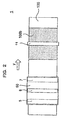
- the printing section 2 is provided therein a platen roll 4 that conveys the image-receiving paper 100 while it supports this image-receiving paper 100, a feed roll 5 that has wound therearound a not-already-used heat-transfer film 50, a thermal head 6 that heats the heat-transfer film 50 that has been delivered from the feed roll 5, and a wind-up roll 7 that takes up the heat-transfer film 50 that has been heated by the thermal head 6.
- a plurality of heat generating portions 6a, ... 6a are arranged apart from each other. The heat generating portions 6a, ...
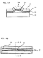
- the heat generating resistor 22, etc. laminated on it are formed in the way that they rise at the center.
- the electrodes 23 are disposed so that they clamp the apex portion of that rise of the heat generating resistor 22.
- Aportion of the wear-resisting layer 24 corresponding to the spacing between the electrodes 23 functions as a heat generating portion 24a.
- the heat generating portion 24a extends over a length corresponding to the plurality of heat generating portions 6a, ... 6a of the thermal head. In this embodiment, the heat generating portion 24a extends over a length corresponding to the entire width of the thermal head.
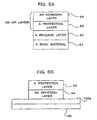
- the image-receiving paper 100 has an image-receiving layer 100a on its upper surface.
- the transfer film 50 has sequentially provided therein in a direction counter to the feeding direction of paper, for example, ink areas of Yellow (Y) , Magenta (M) , and Cyan (C) and an area of overprint (OP) layer.
- the heat generating portions 6a, ... 6a are provided in space intervals from one another, the heating temperatures taken in the direction that goes along the thermal head 6 are not uniform. Therefore, concavo-convex portions are formed in the width direction of the protection layer 53 that has been transferred to the image-receiving paper 100. Further, since the protection layer 53 is transferred while the image-receiving paper 100 is shifted relative to the thermal head by the quantity corresponding to one line, the protection layer 53 also has concavo-convex portions formed in the feeding direction, as well, of the paper. Accordingly, the protection layer 53 is formed like a mat. Therefore, because of irregular reflection of that surface, it results that the image-receiving paper 100 has its luster lost.
- the image-receiving paper 100 When the image-receiving paper 100 is conveyed to the area under the line heater 11, the image-receiving paper 100 is pressed between the platen roller 10 and the line heater 11 in such a way that it is clamped between the both.
- the printer 1 causes the line heater 11 to generate heat until the temperature thereof becomes a softening temperature of the protection layer 53 and, conveys the image-receiving paper 100 using the platen roller 10. For this reason, the convex portions of the protection layer 53 are pressed while they are being heated by the heat generating portion 24a, with the result that the convex portions that have been softened are leveled.
- the concavo-convex portions of the protection layer 53 are made smooth, thereby it is possible to improve the luster of the post-printing image-receiving paper 100.
- the printer 1 can suitably be used for forming a print matter like a photograph and can also be applied to a photographic sealing machine as well.
- the generated-heat temperature of the heat generating portion 24a may be set to a temperature that is higher than the temperature at which the protection layer 53 begins to soften, so that the protection layer 53 can be softened even in a short period of time.
- the printing method is not limited to that in which sublimation heat-transfer is carried out. It may be the one in which melt heat-transfer is carried out, or the one in which heat-sensitive recording paper is rendered a color. It may be any method in which the protection layer is heated by the thermal head, thereby the concavo-convex portions are formed.
- the relative movement between the image-receiving paper 100 and line heater 11 may be realized by moving the line heater 11, or by moving both of the image-receiving paper 100 and the line heater 11.
- the line heater is provided therein a single heat generating portion that has a length corresponding to a plurality of heat generating portions of the thermal head, it is possible, by disposing the line heater so that it may contact with the protective layer and, while causing generation of heat from its heat generating portion, relatively moving the line heater and the printing paper, to soften, flatten, and level the concavo-convex portions stated above. Accordingly, it is possible to make smooth the surface of the printing paper and therefore improve the luster of the printing paper.
Claims (4)
- Verfahren zum Glätten einer Druckpapierfläche (100), die Verfahrensschritte umfassend:Ausbilden einer Schutzschicht (53) auf Bildern auf dem Druckpapier (100) durch die Wärme eines Wärmekopfes (6) mit einer Vielzahl von Wärme erzeugenden Abschnitten (6a, ... 6a), die voneinander beabstandet angeordnet sind;Anordnen eines Linienheizelements (11) mit einem Wärme erzeugenden Abschnitt (24a), der sich kontinuierlich über eine Länge erstreckt, die der Vielzahl von Wärme erzeugenden Abschnitten (6a, ... 6a) des Wärmekopfes (6) entspricht, so dass der Wärme erzeugende Abschnitt (24a) die Schutzschicht (53) kontaktieren kann; undrelatives Bewegen des Linienheizelements (11) und des Druckpapiers (100), während von dem Wärme erzeugenden Abschnitt (24a) des Linienheizelements (11) die Erzeugung von Wärme bewirkt wird.
- Verfahren zum Glätten einer Druckpapierfläche (100) gemäß Anspruch 1, wobei die Schutzschicht (53) wieder abgelöst werden kann.
- Drucker, umfassend:eine Quelle mit Bildern aufnehmendem Papier (100);zumindest eine Walzplatte (4, 10), die so angeordnet ist, dass sie das Bilder aufnehmende Papier (100) in einer Zuführrichtung bewegen kann;einen Druckabschnitt (2), auf dem Bilder auf dem Bilder aufnehmenden Papier (100) durch Wärmeübertragung ausgebildet sind;eine Wärme übertragende Folie (50), umfassend eine Schutzschicht (53);dadurch gekennzeichnet, dass der Drucker umfasst:einen Wärmekopf (6) mit einer Vielzahl von Wärme erzeugenden Abschnitten (6a ... 6a), die voneinander beabstandet angeordnet sind, wobei der Wärmekopf so angeordnet ist, dass die Wärme übertragende Folie (50) im Kontakt mit dem Bilder aufnehmenden Papier (100) erwärmt wird, um ein Übertragen der Schutzschicht (53) auf das Bilder aufnehmende Papier (100), auf dem Bilder ausgebildet sind, zu bewirken; undein Linienheizelement (11) auf einer stromabwärtigen Seite des Wärmekopfes (6) in Zuführrichtung des Bilder aufnehmenden Papiers (100), das einen Heizabschnitt (24a) aufweist, der sich kontinuierlich über eine Länge erstreckt, die der Vielzahl Wärme erzeugender Abschnitte (6a...6a) des Wärmekopfes (6) entspricht, welcher so angeordnet ist, dass er die Schutzschicht (53) auf dem Bilder aufnehmenden Papier (100) erwärmt und glättet.
- Drucker (1) nach Anspruch 3, wobei vorgesehen ist, dass sich das Linienheizelement (11) über die gesamte Breite des Druckpapiers (100) erstreckt.
Applications Claiming Priority (2)
| Application Number | Priority Date | Filing Date | Title |
|---|---|---|---|
| JP2002364619A JP3784366B2 (ja) | 2002-12-17 | 2002-12-17 | 印画紙表面の平滑化方法 |
| JP2002364619 | 2002-12-17 |
Publications (2)
| Publication Number | Publication Date |
|---|---|
| EP1431048A1 EP1431048A1 (de) | 2004-06-23 |
| EP1431048B1 true EP1431048B1 (de) | 2008-12-03 |
Family
ID=32376230
Family Applications (1)
| Application Number | Title | Priority Date | Filing Date |
|---|---|---|---|
| EP03257887A Expired - Fee Related EP1431048B1 (de) | 2002-12-17 | 2003-12-16 | Drucker, Verfahren und Vorrichtung zum Glätten von Druckapier |
Country Status (4)
| Country | Link |
|---|---|
| US (1) | US7009631B2 (de) |
| EP (1) | EP1431048B1 (de) |
| JP (1) | JP3784366B2 (de) |
| DE (1) | DE60325007D1 (de) |
Families Citing this family (7)
| Publication number | Priority date | Publication date | Assignee | Title |
|---|---|---|---|---|
| US7113198B2 (en) * | 2004-09-08 | 2006-09-26 | Pitney Bowes Inc. | Method and system for creation of secure documents using digital embossing of thermal media with thermal print heads |
| JP4544111B2 (ja) | 2005-09-16 | 2010-09-15 | ソニー株式会社 | 画像形成装置及び画像形成方法 |
| JP5056430B2 (ja) * | 2007-08-03 | 2012-10-24 | ソニー株式会社 | 画像形成方法、画像形成装置、表面性改質シート、熱転写シート |
| JP5223317B2 (ja) * | 2007-12-05 | 2013-06-26 | ソニー株式会社 | プリンタ装置及びラミネート方法 |
| JP5151496B2 (ja) * | 2008-01-17 | 2013-02-27 | ソニー株式会社 | 画像形成装置及びそれに用いる改質シートカートリッジ |
| CN201503666U (zh) * | 2009-07-28 | 2010-06-09 | 东莞植富商标印制有限公司 | 一种热转印电子射频识别标签 |
| JP2011167948A (ja) * | 2010-02-19 | 2011-09-01 | Mitsubishi Electric Corp | 熱転写記録装置 |
Family Cites Families (12)
| Publication number | Priority date | Publication date | Assignee | Title |
|---|---|---|---|---|
| JPS59215885A (ja) * | 1983-05-24 | 1984-12-05 | Ricoh Co Ltd | 画像の堅牢化処理法 |
| JPH04103360A (ja) * | 1990-08-23 | 1992-04-06 | Victor Co Of Japan Ltd | 熱溶融透明バインダの転写方法 |
| JP3150372B2 (ja) * | 1991-09-17 | 2001-03-26 | 松下電器産業株式会社 | 熱転写記録方法、装置及び受像体 |
| JP3314980B2 (ja) * | 1993-05-28 | 2002-08-19 | 大日本印刷株式会社 | 熱転写記録方法及び装置 |
| JPH08328404A (ja) * | 1995-05-31 | 1996-12-13 | Kyocera Corp | トナー定着用ヒータ |
| JP3033486B2 (ja) * | 1995-06-30 | 2000-04-17 | 富士ゼロックス株式会社 | 定着方法及びその装置 |
| US5851720A (en) * | 1995-11-14 | 1998-12-22 | Sony Corporation | Transfer material for use in thermal transfer and method of forming thermal transfer images |
| JPH09193433A (ja) * | 1996-01-18 | 1997-07-29 | Rohm Co Ltd | 発熱抵抗体における保護膜 |
| JPH1086420A (ja) | 1996-09-18 | 1998-04-07 | Dainippon Printing Co Ltd | 熱転写記録方式による被熱転写体の表面平滑処理方法及び装置 |
| JPH10291332A (ja) * | 1997-02-19 | 1998-11-04 | Fuji Photo Film Co Ltd | カラー感熱発色プリント方法及び装置並びに平滑化処理装置 |
| JP2002113958A (ja) | 2000-10-12 | 2002-04-16 | Konica Corp | 熱転写記録方法及び印画物 |
| DE60310282T2 (de) * | 2002-03-01 | 2007-05-10 | Dai Nippon Printing Co., Ltd. | Thermisch übertragbares Bildschutzblatt, Verfahren zur Schutzschicht-Bildung und durch das Verfahren hergestellte Aufnahme |
-
2002
- 2002-12-17 JP JP2002364619A patent/JP3784366B2/ja not_active Expired - Fee Related
-
2003
- 2003-12-16 US US10/736,828 patent/US7009631B2/en not_active Expired - Lifetime
- 2003-12-16 EP EP03257887A patent/EP1431048B1/de not_active Expired - Fee Related
- 2003-12-16 DE DE60325007T patent/DE60325007D1/de not_active Expired - Lifetime
Also Published As
| Publication number | Publication date |
|---|---|
| EP1431048A1 (de) | 2004-06-23 |
| JP2004195711A (ja) | 2004-07-15 |
| JP3784366B2 (ja) | 2006-06-07 |
| US7009631B2 (en) | 2006-03-07 |
| DE60325007D1 (de) | 2009-01-15 |
| US20040165052A1 (en) | 2004-08-26 |
Similar Documents
| Publication | Publication Date | Title |
|---|---|---|
| US6390617B1 (en) | Image forming apparatus | |
| KR0136076B1 (ko) | 정착장치 및 이를 갖춘 화상형성장치 | |
| KR101491523B1 (ko) | 화상 형성 방법, 화상 형성 장치, 표면성 개질 시트, 및열전사 시트 | |
| EP1431048B1 (de) | Drucker, Verfahren und Vorrichtung zum Glätten von Druckapier | |
| KR100708167B1 (ko) | Tph를 채용하는 화상형성장치 | |
| JPH0679889A (ja) | サーマルプリンタ | |
| JPH09511459A (ja) | インキを記録媒体に転写するための熱電気式の印刷機 | |
| JP7307894B2 (ja) | 熱転写システムおよび熱転写方法 | |
| JP3314980B2 (ja) | 熱転写記録方法及び装置 | |
| JP2003145846A (ja) | プリンタ | |
| JP4113864B2 (ja) | 熱転写記録方法及び熱転写記録装置 | |
| JP2002067283A (ja) | インクジェット記録装置 | |
| JP2002154724A (ja) | 転写装置と転写物の製造方法 | |
| US6130698A (en) | Heat transfer printer | |
| JP4175121B2 (ja) | オーバーコート装置及びオーバーコート装置付きインクジェット記録装置 | |
| US20060232656A1 (en) | Thermal printer, print head, printing method and substrate for use therewith | |
| EP1520714B1 (de) | Verfahren und Vorrichtung zur thermischen Aufzeichnung durch Übertragung | |
| JP3537502B2 (ja) | 定着装置 | |
| US20080317536A1 (en) | Printer apparatus | |
| JP2690832B2 (ja) | 多色感熱記録装置 | |
| JP2005161823A (ja) | サーマルヘッド及び感熱プリンタ並びに感熱記録システム | |
| JPH0243053A (ja) | インクジエット記録装置 | |
| US4639742A (en) | Method and apparatus for printing an image | |
| JPH0550629A (ja) | ダイレクト感熱記録用サーマルヘツド | |
| JP2012013868A (ja) | 加熱装置 |
Legal Events
| Date | Code | Title | Description |
|---|---|---|---|
| PUAI | Public reference made under article 153(3) epc to a published international application that has entered the european phase |
Free format text: ORIGINAL CODE: 0009012 |
|
| AK | Designated contracting states |
Kind code of ref document: A1 Designated state(s): AT BE BG CH CY CZ DE DK EE ES FI FR GB GR HU IE IT LI LU MC NL PT RO SE SI SK TR |
|
| AX | Request for extension of the european patent |
Extension state: AL LT LV MK |
|
| 17P | Request for examination filed |
Effective date: 20040807 |
|
| AKX | Designation fees paid |
Designated state(s): DE FR GB |
|
| 17Q | First examination report despatched |
Effective date: 20070321 |
|
| GRAP | Despatch of communication of intention to grant a patent |
Free format text: ORIGINAL CODE: EPIDOSNIGR1 |
|
| GRAS | Grant fee paid |
Free format text: ORIGINAL CODE: EPIDOSNIGR3 |
|
| GRAA | (expected) grant |
Free format text: ORIGINAL CODE: 0009210 |
|
| AK | Designated contracting states |
Kind code of ref document: B1 Designated state(s): DE FR GB |
|
| REG | Reference to a national code |
Ref country code: GB Ref legal event code: FG4D |
|
| REF | Corresponds to: |
Ref document number: 60325007 Country of ref document: DE Date of ref document: 20090115 Kind code of ref document: P |
|
| PLBE | No opposition filed within time limit |
Free format text: ORIGINAL CODE: 0009261 |
|
| STAA | Information on the status of an ep patent application or granted ep patent |
Free format text: STATUS: NO OPPOSITION FILED WITHIN TIME LIMIT |
|
| 26N | No opposition filed |
Effective date: 20090904 |
|
| REG | Reference to a national code |
Ref country code: FR Ref legal event code: PLFP Year of fee payment: 13 |
|
| REG | Reference to a national code |
Ref country code: FR Ref legal event code: PLFP Year of fee payment: 14 |
|
| REG | Reference to a national code |
Ref country code: FR Ref legal event code: PLFP Year of fee payment: 15 |
|
| PGFP | Annual fee paid to national office [announced via postgrant information from national office to epo] |
Ref country code: GB Payment date: 20201223 Year of fee payment: 18 Ref country code: DE Payment date: 20201211 Year of fee payment: 18 Ref country code: FR Payment date: 20201223 Year of fee payment: 18 |
|
| REG | Reference to a national code |
Ref country code: DE Ref legal event code: R119 Ref document number: 60325007 Country of ref document: DE |
|
| GBPC | Gb: european patent ceased through non-payment of renewal fee |
Effective date: 20211216 |
|
| PG25 | Lapsed in a contracting state [announced via postgrant information from national office to epo] |
Ref country code: GB Free format text: LAPSE BECAUSE OF NON-PAYMENT OF DUE FEES Effective date: 20211216 Ref country code: DE Free format text: LAPSE BECAUSE OF NON-PAYMENT OF DUE FEES Effective date: 20220701 |
|
| PG25 | Lapsed in a contracting state [announced via postgrant information from national office to epo] |
Ref country code: FR Free format text: LAPSE BECAUSE OF NON-PAYMENT OF DUE FEES Effective date: 20211231 |