EP1424138A2 - Leimdosierung in einem Leimwerk - Google Patents
Leimdosierung in einem Leimwerk Download PDFInfo
- Publication number
- EP1424138A2 EP1424138A2 EP03025557A EP03025557A EP1424138A2 EP 1424138 A2 EP1424138 A2 EP 1424138A2 EP 03025557 A EP03025557 A EP 03025557A EP 03025557 A EP03025557 A EP 03025557A EP 1424138 A2 EP1424138 A2 EP 1424138A2
- Authority
- EP
- European Patent Office
- Prior art keywords
- glue
- roller
- rollers
- reservoir
- contact
- Prior art date
- Legal status (The legal status is an assumption and is not a legal conclusion. Google has not performed a legal analysis and makes no representation as to the accuracy of the status listed.)
- Granted
Links
- 238000004026 adhesive bonding Methods 0.000 title claims description 8
- 238000000034 method Methods 0.000 claims abstract description 4
- 239000003292 glue Substances 0.000 claims description 80
- 230000002093 peripheral effect Effects 0.000 claims description 10
- 230000002441 reversible effect Effects 0.000 claims description 3
- 239000000853 adhesive Substances 0.000 abstract description 4
- 230000001070 adhesive effect Effects 0.000 abstract description 4
- 239000011248 coating agent Substances 0.000 abstract 2
- 238000000576 coating method Methods 0.000 abstract 2
- 238000007789 sealing Methods 0.000 description 4
- 230000000694 effects Effects 0.000 description 2
- 238000011109 contamination Methods 0.000 description 1
- 230000001419 dependent effect Effects 0.000 description 1
- 230000035945 sensitivity Effects 0.000 description 1
Images
Classifications
-
- B—PERFORMING OPERATIONS; TRANSPORTING
- B05—SPRAYING OR ATOMISING IN GENERAL; APPLYING FLUENT MATERIALS TO SURFACES, IN GENERAL
- B05C—APPARATUS FOR APPLYING FLUENT MATERIALS TO SURFACES, IN GENERAL
- B05C1/00—Apparatus in which liquid or other fluent material is applied to the surface of the work by contact with a member carrying the liquid or other fluent material, e.g. a porous member loaded with a liquid to be applied as a coating
- B05C1/04—Apparatus in which liquid or other fluent material is applied to the surface of the work by contact with a member carrying the liquid or other fluent material, e.g. a porous member loaded with a liquid to be applied as a coating for applying liquid or other fluent material to work of indefinite length
- B05C1/08—Apparatus in which liquid or other fluent material is applied to the surface of the work by contact with a member carrying the liquid or other fluent material, e.g. a porous member loaded with a liquid to be applied as a coating for applying liquid or other fluent material to work of indefinite length using a roller or other rotating member which contacts the work along a generating line
- B05C1/0826—Apparatus in which liquid or other fluent material is applied to the surface of the work by contact with a member carrying the liquid or other fluent material, e.g. a porous member loaded with a liquid to be applied as a coating for applying liquid or other fluent material to work of indefinite length using a roller or other rotating member which contacts the work along a generating line the work being a web or sheets
- B05C1/0834—Apparatus in which liquid or other fluent material is applied to the surface of the work by contact with a member carrying the liquid or other fluent material, e.g. a porous member loaded with a liquid to be applied as a coating for applying liquid or other fluent material to work of indefinite length using a roller or other rotating member which contacts the work along a generating line the work being a web or sheets the coating roller co-operating with other rollers, e.g. dosing, transfer rollers
-
- B—PERFORMING OPERATIONS; TRANSPORTING
- B31—MAKING ARTICLES OF PAPER, CARDBOARD OR MATERIAL WORKED IN A MANNER ANALOGOUS TO PAPER; WORKING PAPER, CARDBOARD OR MATERIAL WORKED IN A MANNER ANALOGOUS TO PAPER
- B31B—MAKING CONTAINERS OF PAPER, CARDBOARD OR MATERIAL WORKED IN A MANNER ANALOGOUS TO PAPER
- B31B2150/00—Flexible containers made from sheets or blanks, e.g. from flattened tubes
-
- B—PERFORMING OPERATIONS; TRANSPORTING
- B31—MAKING ARTICLES OF PAPER, CARDBOARD OR MATERIAL WORKED IN A MANNER ANALOGOUS TO PAPER; WORKING PAPER, CARDBOARD OR MATERIAL WORKED IN A MANNER ANALOGOUS TO PAPER
- B31B—MAKING CONTAINERS OF PAPER, CARDBOARD OR MATERIAL WORKED IN A MANNER ANALOGOUS TO PAPER
- B31B2160/00—Shape of flexible containers
- B31B2160/20—Shape of flexible containers with structural provision for thickness of contents
-
- B—PERFORMING OPERATIONS; TRANSPORTING
- B31—MAKING ARTICLES OF PAPER, CARDBOARD OR MATERIAL WORKED IN A MANNER ANALOGOUS TO PAPER; WORKING PAPER, CARDBOARD OR MATERIAL WORKED IN A MANNER ANALOGOUS TO PAPER
- B31B—MAKING CONTAINERS OF PAPER, CARDBOARD OR MATERIAL WORKED IN A MANNER ANALOGOUS TO PAPER
- B31B70/00—Making flexible containers, e.g. envelopes or bags
- B31B70/60—Uniting opposed surfaces or edges; Taping
-
- B—PERFORMING OPERATIONS; TRANSPORTING
- B31—MAKING ARTICLES OF PAPER, CARDBOARD OR MATERIAL WORKED IN A MANNER ANALOGOUS TO PAPER; WORKING PAPER, CARDBOARD OR MATERIAL WORKED IN A MANNER ANALOGOUS TO PAPER
- B31B—MAKING CONTAINERS OF PAPER, CARDBOARD OR MATERIAL WORKED IN A MANNER ANALOGOUS TO PAPER
- B31B70/00—Making flexible containers, e.g. envelopes or bags
- B31B70/60—Uniting opposed surfaces or edges; Taping
- B31B70/62—Uniting opposed surfaces or edges; Taping by adhesives
-
- Y—GENERAL TAGGING OF NEW TECHNOLOGICAL DEVELOPMENTS; GENERAL TAGGING OF CROSS-SECTIONAL TECHNOLOGIES SPANNING OVER SEVERAL SECTIONS OF THE IPC; TECHNICAL SUBJECTS COVERED BY FORMER USPC CROSS-REFERENCE ART COLLECTIONS [XRACs] AND DIGESTS
- Y10—TECHNICAL SUBJECTS COVERED BY FORMER USPC
- Y10T—TECHNICAL SUBJECTS COVERED BY FORMER US CLASSIFICATION
- Y10T156/00—Adhesive bonding and miscellaneous chemical manufacture
- Y10T156/17—Surface bonding means and/or assemblymeans with work feeding or handling means
- Y10T156/1798—Surface bonding means and/or assemblymeans with work feeding or handling means with liquid adhesive or adhesive activator applying means
Definitions
- the invention relates to a glue unit for a floor laying device for Cross-bottom bags according to the preamble of claim 1
- Such gluing units are, for example, from the patent DE 195 32 582 known.
- a gluing unit of the known type consists of at least one Dosing and a glue application roller that comes into contact with one as a housing trained glue reservoir.
- the metering roller has the same Direction of rotation like the glue application roller, so that it also functions as Sealing roller can be called.
- the one from the glue application roller glue taken up is removed from the plate or format roller and transferred from this to the workpiece to be glued.
- the dosing and the glue applicator roller are on a common toothed belt driven, which is set in motion by a toothed belt pulley.
- the amount of glue to be transferred is determined by the gap between the metering and the glue application roller. If, for example, no glue is to be transferred, the gap between the two rollers is closed. The larger the gap is selected, the more glue is transferred to the format roller and from there to the workpiece to be glued. The distance is set, for example, starting from a piston-cylinder unit via a mechanical linkage.
- the object of the invention is a device propose a dosage of the amount of glue to be transferred without the Allows use of a mechanism for distance control and thereby has a very high sensitivity in the glue quantity regulation.
- this object is achieved through the features of characterizing part of claim 1 solved. So they are Circumferential speeds of the glue application roller and the format or Cliché roller independently adjustable. This can do that Ratio of the peripheral speeds of both rollers can be chosen freely.
- peripheral speed of the metering roller independently of the other two rollers, since these, as in the Introduction described, has a sealing effect. Through a suitable choice of This sealing effect can be influenced at circumferential speed.
- At least one of the three rollers belonging to the gluing unit has its own drive.
- At least one of the rollers mentioned has a Drive motor has that of a power electronic power station is powered.
- the mentioned drive means can be controlled by a control device.
- the Control device has a computing unit that is dependent on the desired amount of glue or from the desired change of Glue application amount the peripheral speeds of the glue transport adjusts the rollers involved and coordinates them.
- control device in the setting and Coordination of the peripheral speeds of the rolls of one preset circumferential speed of the format roller.
- the control device can then, for example, by multiplication by one preset ratio between the peripheral speeds that Control the speed of at least one other roller.
- the invention further comprises a method for controlling the amount of glue for a glue unit of a floor laying device for cross-bottom bags, the Leimwerk glued bottom label, valve label or cross bottoms and at least one Glue reservoir and / or a glue source, one in contact with the glue reservoir upright metering roller, a glue application roller, with the glue reservoir or the glue source can be in contact, a format roller, the glue from the glue application roller takes off and releases it to the workpieces to be glued, comprises and wherein said rollers are associated with drive means.
- the method according to the invention is characterized in that the ratio of the Circumferential speeds of the glue application roller and the format roller for Control of the amount of glue applied is varied.
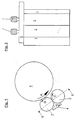
- Fig. 1 shows a plan view of a gluing unit according to the invention.
- the glue 7 is a glue housing 4 and is from the glue application roller 2nd removed and transferred to the format roller 1.
- the metering roller 3 carries Make sure that the glue 7 does not come out of the glue housing 4 unintentionally.
- the direction of rotation C of the metering roller 3 is reversible while it is in Generally makes no sense, the directions of rotation A and B of the format roller 1 or to change the glue application roller 2.
- FIG. 2 shows the section II-II in FIG. 1.
- the glue application roller 2 and the metering roller 3 are mounted hanging in one end in a carrier plate 5.
- two electric motors 6 are fastened, the drive shafts of which act on the axes of one of the two rollers mentioned.
- the carrier plate 5 is fastened in the machine frame in a manner not shown, like the format roller 1.
- the circumferential speeds of the rollers 2, 3 can be adjusted in accordance with the requirements of the glue transfer and glue application by the electric motors 6, which are supplied with power by power controllers, also not shown, which can be controlled via a control unit.
Landscapes
- Coating Apparatus (AREA)
- Making Paper Articles (AREA)
- Package Closures (AREA)
- Medicines Containing Plant Substances (AREA)
- Cultivation Of Plants (AREA)
- Adhesives Or Adhesive Processes (AREA)
- Pretreatment Of Seeds And Plants (AREA)
Abstract
Description
Die Einstellung des Abstandes erfolgt dabei beispielsweise ausgehend von einer Kolbenzylindereinheit über ein mechanisches Gestänge.
Die einzelnen Figuren zeigen:
- Fig. 1
- Draufsicht auf ein erfindungsgemäßes Leimwerk
- Fig. 2
- Seitenansicht des Leimwerks gemäß Schnittlinie II-II in Fig. 1
| Bezugszeichenliste | |
| 1 | Formatwalze |
| 2 | Leimauftragswalze |
| 3 | Dosierwalze |
| 4 | Leimgehäuse |
| 5 | Tragplatte |
| 6 | Elektromotor |
| 7 | Leim |
| 8 | |
| 9 | |
| A | Drehrichtung der Formatwalze 1 |
| B | Drehrichtung der Leimauftragswalze 2 |
| C | Drehrichtung der Dosierwalze 3 |
Claims (8)
- Leimwerk für eine Bodenlegevorrichtung für Kreuzbodensäcke, welche aus Schlauchstücken gebildet werden, zur Beleimung von Bodenzettel oder Kreuzbodensäcken und zumindest folgende Merkmale aufweist:dadurch gekennzeichnet, dassein Leimreservoir (4) und/oder eine Leimquelleeine Dosierwalze (3), welche in Kontakt mit dem Leimreservoir (4) stehteine Leimauftragswalze (2), die in Kontakt mit dem Leimreservoir (4) oder der Leimquelle stehen kann,eine Formatwalze (1), welche in Kontakt zu der Leimauftragswalze (2) steht und Leim (7) von dieser Walze (2) auf die Bodenzettel oder Kreuzböden überträgtwobei den oben angeführten Walzen (1,2,3) Antriebsmittel zugeordnet sind
die Umfangsgeschwindigkeit der Leimauftragswalze (2) und der Formatwalze (1) unabhängig voneinander einstellbar ist. - Leimwerk nach Anspruch 1
dadurch gekennzeichnet, dass
auch die Umfangsgeschwindigkeit der Dosierwalze (3) unabhängig von den beiden anderen Walzen (1, 2) einstellbar ist. - Leimwerk nach Anspruch 2
dadurch gekennzeichnet, dass
die Drehrichtung (C) der Dosierwalze (3) umkehrbar ist. - Leimwerk nach einem der vorstehenden Ansprüche
dadurch gekennzeichnet, dass
zumindest eine der vorgenannten Walzen (1,2,3) über einen eigenen Antriebsmotor (6) verfügt. - Leimwerk nach einem der vorstehenden Ansprüche
dadurch gekennzeichnet, dass
zumindest eine der vorgenannten Walzen (1,2,3) über einen eigenen Antriebsmotor (6) verfügt, welcher von einem leistungselektronischen Leistungssteller - wie einem Frequenzumrichter - mit Strom versorgt wird. - Leimwerk nach einem der vorstehenden Ansprüche
dadurch gekennzeichnet, dassdie Antriebsmittel (6) von einer Steuervorrichtung ansteuerbar sind,welche über eine Recheneinheit verfügt, die in Abhängigkeit von von dem Maschinenbediener gewünschtendie Umfangsgeschwindigkeit der am Leimtransport beteiligten Walzen (1,2,3) einstellt und aufeinander abstimmt.Leimauftragsmengen oderÄnderungen der Leimauftragsmengen - Leimwerk nach Anspruch 6
dadurch gekennzeichnet, dass
die Steuervorrichtung bei der Einstellung und Abstimmung der Umfangsgeschwindigkeit der Walzen (1, 2, 3) von der Geschwindigkeit der Formatwalze (1) ausgeht. - Verfahren zur Steuerung der Leimenge für ein Leimwerk einer Bodenlegevorrichtung für Kreuzbodensäcke,
wobei das Leimwerk Bodenzettel oder Kreuzböden beleimt und zumindest folgende Merkmale aufweist:dadurch gekennzeichnet, dassein Leimreservoir (4) und/oder eine Leimquelleeine Dosierwalze (3), welche in Kontakt mit dem Leimreservoir (4) stehteine Leimauftragswalze (2), die in Kontakt mit dem Leimreservoir (4) oder der Leimquelle stehen kann,eine Formatwalze (1), welche in Kontakt zu der Leimauftragswalze (2) steht und Leim von dieser Walze (2) auf die Bodenzettel oder Kreuzböden überträgtwobei den oben angeführten Walzen (1, 2, 3) Antriebsmittel (6) zugeordnet sind
das Verhältnis der Umfangsgeschwindigkeiten der Leimauftragswalze (2) und der Formatwalze (3) zur Steuerung der Leimauftragsmenge variiert wird.
Applications Claiming Priority (2)
| Application Number | Priority Date | Filing Date | Title |
|---|---|---|---|
| DE10255484A DE10255484A1 (de) | 2002-11-27 | 2002-11-27 | Leimdosierung in einem Leimwerk |
| DE10255484 | 2002-11-27 |
Publications (3)
| Publication Number | Publication Date |
|---|---|
| EP1424138A2 true EP1424138A2 (de) | 2004-06-02 |
| EP1424138A3 EP1424138A3 (de) | 2007-04-11 |
| EP1424138B1 EP1424138B1 (de) | 2009-01-14 |
Family
ID=32240488
Family Applications (1)
| Application Number | Title | Priority Date | Filing Date |
|---|---|---|---|
| EP03025557A Expired - Lifetime EP1424138B1 (de) | 2002-11-27 | 2003-11-08 | Leimdosierung in einem Leimwerk |
Country Status (6)
| Country | Link |
|---|---|
| US (1) | US7018471B2 (de) |
| EP (1) | EP1424138B1 (de) |
| AT (1) | ATE420735T1 (de) |
| CA (1) | CA2450958C (de) |
| DE (2) | DE10255484A1 (de) |
| ES (1) | ES2318082T3 (de) |
Families Citing this family (7)
| Publication number | Priority date | Publication date | Assignee | Title |
|---|---|---|---|---|
| US7638008B2 (en) * | 2004-05-25 | 2009-12-29 | New Spirit Backing Llc | Polyurethane roller coating process for carpet backing |
| MXPA06013712A (es) | 2004-05-25 | 2007-08-15 | Kusters Zima Corp | Dispositivo aplicador de poliuretano con rodillo, para respaldo de alfombras. |
| DE102005006064A1 (de) * | 2005-02-10 | 2006-08-24 | Man Roland Druckmaschinen Ag | Vorrichtung zum Auftragen eines Fluids auf eine Druckform |
| DE102007018730B4 (de) * | 2007-04-20 | 2010-08-19 | Windmöller & Hölscher Kg | Verfahren und Vorrichtung zum Auftragen von Leim auf Bestandteile von Werkstücken zur Herstellung von Säcken und Beuteln |
| DE102012219554A1 (de) | 2012-10-25 | 2014-04-30 | Krones Ag | Leimwerk |
| US9914151B2 (en) | 2015-10-14 | 2018-03-13 | Bendix Commercial Vehicle Systems Llc | Method of applying adhesive to an outer circumferential surface of a cylindrical compressor liner and an adhesive applicator apparatus therefor |
| CN108435494A (zh) * | 2018-04-04 | 2018-08-24 | 中山松德新材料装备有限公司 | 一种用于高速预涂膜的三辊ac涂布结构 |
Citations (1)
| Publication number | Priority date | Publication date | Assignee | Title |
|---|---|---|---|---|
| DE19532582C1 (de) | 1995-09-04 | 1996-12-05 | Windmoeller & Hoelscher | Klebstoffauftragsvorrichtung |
Family Cites Families (8)
| Publication number | Priority date | Publication date | Assignee | Title |
|---|---|---|---|---|
| US2676563A (en) * | 1949-02-05 | 1954-04-27 | Champion Paper & Fibre Co | Apparatus for coating paper |
| DE1123549B (de) * | 1959-04-30 | 1962-02-08 | Bates Ventil Saekke Co As | Leimauftragvorrichtung an Maschinen, insbesondere zur Herstellung von Beuteln oder Saecken |
| US3986452A (en) * | 1960-05-02 | 1976-10-19 | Dahlgren Manufacturing Company, Inc. | Liquid applicator for lithographic systems |
| DE2833377C3 (de) * | 1978-07-29 | 1981-02-12 | Nippon Steel Corp., Tokio | Verfahren zum Aufbringen von"·*08"" Beschichtungsmaterial auf ein Metallband sowie Vorrichtung zur Durchführung dieses Verfahrens |
| US4308796A (en) * | 1979-07-13 | 1982-01-05 | S-W-H, Ltd. | Offset lithographic press with ink metering system for blanket cylinder |
| DE3876626T2 (de) * | 1986-08-11 | 1993-06-03 | Cons Paper Inc | Verfahren und einrichtung zum kontrollierten aufbringen von klebstoff auf definierte orte. |
| CA2078436A1 (en) * | 1990-03-16 | 1991-09-17 | H. Richard Vermehren | Gummer roll apparatus |
| US5972167A (en) * | 1993-11-16 | 1999-10-26 | Nippon Paper Industries Co., Ltd. | Transfer roll coating color and a coated paper |
-
2002
- 2002-11-27 DE DE10255484A patent/DE10255484A1/de not_active Ceased
-
2003
- 2003-11-08 EP EP03025557A patent/EP1424138B1/de not_active Expired - Lifetime
- 2003-11-08 DE DE50311084T patent/DE50311084D1/de not_active Expired - Lifetime
- 2003-11-08 ES ES03025557T patent/ES2318082T3/es not_active Expired - Lifetime
- 2003-11-08 AT AT03025557T patent/ATE420735T1/de not_active IP Right Cessation
- 2003-11-26 US US10/721,890 patent/US7018471B2/en not_active Expired - Fee Related
- 2003-11-27 CA CA2450958A patent/CA2450958C/en not_active Expired - Fee Related
Patent Citations (1)
| Publication number | Priority date | Publication date | Assignee | Title |
|---|---|---|---|---|
| DE19532582C1 (de) | 1995-09-04 | 1996-12-05 | Windmoeller & Hoelscher | Klebstoffauftragsvorrichtung |
Also Published As
| Publication number | Publication date |
|---|---|
| CA2450958A1 (en) | 2004-05-27 |
| US7018471B2 (en) | 2006-03-28 |
| US20040103990A1 (en) | 2004-06-03 |
| EP1424138B1 (de) | 2009-01-14 |
| DE10255484A1 (de) | 2004-06-24 |
| EP1424138A3 (de) | 2007-04-11 |
| DE50311084D1 (de) | 2009-03-05 |
| ES2318082T3 (es) | 2009-05-01 |
| ATE420735T1 (de) | 2009-01-15 |
| CA2450958C (en) | 2012-03-27 |
Similar Documents
| Publication | Publication Date | Title |
|---|---|---|
| EP0673766B1 (de) | Einrichtung zur Bearbeitung von Lagenmaterial oder dgl. | |
| EP1437303B2 (de) | Verfahren und Vorrichtung zum Beleimen von Verpackungsmaterial | |
| EP1118564B1 (de) | Fördervorrichtung | |
| DE2703288A1 (de) | Verfahren und vorrichtung zum siegeln einer naht eines strangfoermigen produktes der tabakverarbeitenden industrie | |
| DE102005022269A1 (de) | Verfahren und Anlage zum Herstellen eines Hygieneartikels, insbesondere einer Windel | |
| DE2934496C2 (de) | Vorrichtung zur Positionsaussteuerung des Auftrages von Leim oder dergleichen auf eine laufende Bahn | |
| DE10255484A1 (de) | Leimdosierung in einem Leimwerk | |
| DE3148037C2 (de) | Vorrichtung zum intermittierenden Auftragen von Klebstoff | |
| EP0995598A1 (de) | Anordnung zum Zuführen von fliessfähiger Druckfarbe zu einem Druckwerk für einen Zigarettenpapierstreifen | |
| DE3641213A1 (de) | Reversible mit eingebauten vorrichtungen zur befeuchtung und lackierung versehene druckeinheit fuer offsetmaschinen | |
| DE2151218A1 (de) | Verfahren und Vorrichtung zum Stanzen von Fenstern in Rohlinge aus blattfoermigem Material | |
| EP0584301B1 (de) | Mischmaschine | |
| EP2136932B1 (de) | Verfahren und vorrichtung zum auftragen von leim auf bestandteile von werkstücken zur herstellung von säcken und beuteln | |
| DE2640883A1 (de) | Automatische vorrichtung zur lageregelung des randes eines laufenden bandes | |
| EP0903308B1 (de) | Zellenrad zur Uebergabe von Gegenständen von einem ersten Fördermittel an ein zweites Fördermittel | |
| EP0690175B1 (de) | Airless-Spritzverfahren zur Herstellung von Markierungslinien auf Strassen und Vorrichtung zur Durchführung des Verfahrens | |
| DE2654932C2 (de) | Vorrichtung zum Herstellen von Papierzylindern zum Züchten von Säumlingen | |
| EP0927412A2 (de) | Vorrichtung zum herstellen eines streifens mit selbstklebenden etiketten oder anderen materialien mit unterlegten teilen sowie zur seitlichen kantenführung | |
| DE10327647B4 (de) | Bodenlegevorrichtung | |
| DE19538166C2 (de) | Vorrichtung und Verfahren zum kontinuierlichen Beleimen von Faltschachtelzuschnitten | |
| DE2362768C2 (de) | Fördervorrichtung durch eine Strahlanlage | |
| DE1911410A1 (de) | Lenkbares Fahrwerk mit Antrieb | |
| DE1504026C3 (de) | ||
| DE19645092A1 (de) | Verfahren und Vorrichtung zum Bearbeiten von Druckprodukten, die in einem Hochleistungsförderstrom zugeführt werden | |
| DE3807485C2 (de) |
Legal Events
| Date | Code | Title | Description |
|---|---|---|---|
| PUAI | Public reference made under article 153(3) epc to a published international application that has entered the european phase |
Free format text: ORIGINAL CODE: 0009012 |
|
| AK | Designated contracting states |
Kind code of ref document: A2 Designated state(s): AT BE BG CH CY CZ DE DK EE ES FI FR GB GR HU IE IT LI LU MC NL PT RO SE SI SK TR |
|
| AX | Request for extension of the european patent |
Extension state: AL LT LV MK |
|
| PUAL | Search report despatched |
Free format text: ORIGINAL CODE: 0009013 |
|
| AK | Designated contracting states |
Kind code of ref document: A3 Designated state(s): AT BE BG CH CY CZ DE DK EE ES FI FR GB GR HU IE IT LI LU MC NL PT RO SE SI SK TR |
|
| AX | Request for extension of the european patent |
Extension state: AL LT LV MK |
|
| 17P | Request for examination filed |
Effective date: 20071011 |
|
| AKX | Designation fees paid |
Designated state(s): AT BE BG CH CY CZ DE DK EE ES FI FR GB GR HU IE IT LI LU MC NL PT RO SE SI SK TR |
|
| 17Q | First examination report despatched |
Effective date: 20080218 |
|
| GRAP | Despatch of communication of intention to grant a patent |
Free format text: ORIGINAL CODE: EPIDOSNIGR1 |
|
| GRAS | Grant fee paid |
Free format text: ORIGINAL CODE: EPIDOSNIGR3 |
|
| GRAS | Grant fee paid |
Free format text: ORIGINAL CODE: EPIDOSNIGR3 |
|
| GRAA | (expected) grant |
Free format text: ORIGINAL CODE: 0009210 |
|
| AK | Designated contracting states |
Kind code of ref document: B1 Designated state(s): AT BE BG CH CY CZ DE DK EE ES FI FR GB GR HU IE IT LI LU MC NL PT RO SE SI SK TR |
|
| REG | Reference to a national code |
Ref country code: GB Ref legal event code: FG4D Free format text: NOT ENGLISH |
|
| REG | Reference to a national code |
Ref country code: CH Ref legal event code: EP |
|
| REG | Reference to a national code |
Ref country code: IE Ref legal event code: FG4D Free format text: LANGUAGE OF EP DOCUMENT: GERMAN |
|
| REF | Corresponds to: |
Ref document number: 50311084 Country of ref document: DE Date of ref document: 20090305 Kind code of ref document: P |
|
| REG | Reference to a national code |
Ref country code: ES Ref legal event code: FG2A Ref document number: 2318082 Country of ref document: ES Kind code of ref document: T3 |
|
| PG25 | Lapsed in a contracting state [announced via postgrant information from national office to epo] |
Ref country code: NL Free format text: LAPSE BECAUSE OF FAILURE TO SUBMIT A TRANSLATION OF THE DESCRIPTION OR TO PAY THE FEE WITHIN THE PRESCRIBED TIME-LIMIT Effective date: 20090114 |
|
| NLV1 | Nl: lapsed or annulled due to failure to fulfill the requirements of art. 29p and 29m of the patents act | ||
| PG25 | Lapsed in a contracting state [announced via postgrant information from national office to epo] |
Ref country code: FI Free format text: LAPSE BECAUSE OF FAILURE TO SUBMIT A TRANSLATION OF THE DESCRIPTION OR TO PAY THE FEE WITHIN THE PRESCRIBED TIME-LIMIT Effective date: 20090114 Ref country code: SI Free format text: LAPSE BECAUSE OF FAILURE TO SUBMIT A TRANSLATION OF THE DESCRIPTION OR TO PAY THE FEE WITHIN THE PRESCRIBED TIME-LIMIT Effective date: 20090114 |
|
| REG | Reference to a national code |
Ref country code: IE Ref legal event code: FD4D |
|
| PG25 | Lapsed in a contracting state [announced via postgrant information from national office to epo] |
Ref country code: SE Free format text: LAPSE BECAUSE OF FAILURE TO SUBMIT A TRANSLATION OF THE DESCRIPTION OR TO PAY THE FEE WITHIN THE PRESCRIBED TIME-LIMIT Effective date: 20090414 Ref country code: PT Free format text: LAPSE BECAUSE OF FAILURE TO SUBMIT A TRANSLATION OF THE DESCRIPTION OR TO PAY THE FEE WITHIN THE PRESCRIBED TIME-LIMIT Effective date: 20090615 |
|
| PG25 | Lapsed in a contracting state [announced via postgrant information from national office to epo] |
Ref country code: DK Free format text: LAPSE BECAUSE OF FAILURE TO SUBMIT A TRANSLATION OF THE DESCRIPTION OR TO PAY THE FEE WITHIN THE PRESCRIBED TIME-LIMIT Effective date: 20090114 Ref country code: IE Free format text: LAPSE BECAUSE OF FAILURE TO SUBMIT A TRANSLATION OF THE DESCRIPTION OR TO PAY THE FEE WITHIN THE PRESCRIBED TIME-LIMIT Effective date: 20090114 Ref country code: EE Free format text: LAPSE BECAUSE OF FAILURE TO SUBMIT A TRANSLATION OF THE DESCRIPTION OR TO PAY THE FEE WITHIN THE PRESCRIBED TIME-LIMIT Effective date: 20090114 Ref country code: CZ Free format text: LAPSE BECAUSE OF FAILURE TO SUBMIT A TRANSLATION OF THE DESCRIPTION OR TO PAY THE FEE WITHIN THE PRESCRIBED TIME-LIMIT Effective date: 20090114 |
|
| PLBE | No opposition filed within time limit |
Free format text: ORIGINAL CODE: 0009261 |
|
| STAA | Information on the status of an ep patent application or granted ep patent |
Free format text: STATUS: NO OPPOSITION FILED WITHIN TIME LIMIT |
|
| PG25 | Lapsed in a contracting state [announced via postgrant information from national office to epo] |
Ref country code: RO Free format text: LAPSE BECAUSE OF FAILURE TO SUBMIT A TRANSLATION OF THE DESCRIPTION OR TO PAY THE FEE WITHIN THE PRESCRIBED TIME-LIMIT Effective date: 20090114 Ref country code: SK Free format text: LAPSE BECAUSE OF FAILURE TO SUBMIT A TRANSLATION OF THE DESCRIPTION OR TO PAY THE FEE WITHIN THE PRESCRIBED TIME-LIMIT Effective date: 20090114 |
|
| 26N | No opposition filed |
Effective date: 20091015 |
|
| PG25 | Lapsed in a contracting state [announced via postgrant information from national office to epo] |
Ref country code: BG Free format text: LAPSE BECAUSE OF FAILURE TO SUBMIT A TRANSLATION OF THE DESCRIPTION OR TO PAY THE FEE WITHIN THE PRESCRIBED TIME-LIMIT Effective date: 20090414 |
|
| BERE | Be: lapsed |
Owner name: WINDMOLLER & HOLSCHER K.G. Effective date: 20091130 |
|
| PG25 | Lapsed in a contracting state [announced via postgrant information from national office to epo] |
Ref country code: MC Free format text: LAPSE BECAUSE OF NON-PAYMENT OF DUE FEES Effective date: 20091130 |
|
| REG | Reference to a national code |
Ref country code: CH Ref legal event code: PL |
|
| GBPC | Gb: european patent ceased through non-payment of renewal fee |
Effective date: 20091108 |
|
| REG | Reference to a national code |
Ref country code: FR Ref legal event code: ST Effective date: 20100730 |
|
| PG25 | Lapsed in a contracting state [announced via postgrant information from national office to epo] |
Ref country code: BE Free format text: LAPSE BECAUSE OF NON-PAYMENT OF DUE FEES Effective date: 20091130 Ref country code: LI Free format text: LAPSE BECAUSE OF NON-PAYMENT OF DUE FEES Effective date: 20091130 Ref country code: GR Free format text: LAPSE BECAUSE OF FAILURE TO SUBMIT A TRANSLATION OF THE DESCRIPTION OR TO PAY THE FEE WITHIN THE PRESCRIBED TIME-LIMIT Effective date: 20090415 Ref country code: FR Free format text: LAPSE BECAUSE OF NON-PAYMENT OF DUE FEES Effective date: 20091130 Ref country code: CH Free format text: LAPSE BECAUSE OF NON-PAYMENT OF DUE FEES Effective date: 20091130 |
|
| PG25 | Lapsed in a contracting state [announced via postgrant information from national office to epo] |
Ref country code: GB Free format text: LAPSE BECAUSE OF NON-PAYMENT OF DUE FEES Effective date: 20091108 |
|
| PG25 | Lapsed in a contracting state [announced via postgrant information from national office to epo] |
Ref country code: AT Free format text: LAPSE BECAUSE OF NON-PAYMENT OF DUE FEES Effective date: 20091108 |
|
| PG25 | Lapsed in a contracting state [announced via postgrant information from national office to epo] |
Ref country code: LU Free format text: LAPSE BECAUSE OF NON-PAYMENT OF DUE FEES Effective date: 20091108 |
|
| PG25 | Lapsed in a contracting state [announced via postgrant information from national office to epo] |
Ref country code: HU Free format text: LAPSE BECAUSE OF FAILURE TO SUBMIT A TRANSLATION OF THE DESCRIPTION OR TO PAY THE FEE WITHIN THE PRESCRIBED TIME-LIMIT Effective date: 20090715 |
|
| PG25 | Lapsed in a contracting state [announced via postgrant information from national office to epo] |
Ref country code: TR Free format text: LAPSE BECAUSE OF FAILURE TO SUBMIT A TRANSLATION OF THE DESCRIPTION OR TO PAY THE FEE WITHIN THE PRESCRIBED TIME-LIMIT Effective date: 20090114 |
|
| PG25 | Lapsed in a contracting state [announced via postgrant information from national office to epo] |
Ref country code: CY Free format text: LAPSE BECAUSE OF FAILURE TO SUBMIT A TRANSLATION OF THE DESCRIPTION OR TO PAY THE FEE WITHIN THE PRESCRIBED TIME-LIMIT Effective date: 20090114 |
|
| PGFP | Annual fee paid to national office [announced via postgrant information from national office to epo] |
Ref country code: DE Payment date: 20181130 Year of fee payment: 16 |
|
| PGFP | Annual fee paid to national office [announced via postgrant information from national office to epo] |
Ref country code: ES Payment date: 20181218 Year of fee payment: 16 Ref country code: IT Payment date: 20181122 Year of fee payment: 16 |
|
| REG | Reference to a national code |
Ref country code: DE Ref legal event code: R119 Ref document number: 50311084 Country of ref document: DE |
|
| PG25 | Lapsed in a contracting state [announced via postgrant information from national office to epo] |
Ref country code: DE Free format text: LAPSE BECAUSE OF NON-PAYMENT OF DUE FEES Effective date: 20200603 Ref country code: IT Free format text: LAPSE BECAUSE OF NON-PAYMENT OF DUE FEES Effective date: 20191108 |
|
| REG | Reference to a national code |
Ref country code: ES Ref legal event code: FD2A Effective date: 20210414 |
|
| PG25 | Lapsed in a contracting state [announced via postgrant information from national office to epo] |
Ref country code: ES Free format text: LAPSE BECAUSE OF NON-PAYMENT OF DUE FEES Effective date: 20191109 |