EP1416176A2 - Walzenanordnung mit schwenkbarem Zuganker - Google Patents
Walzenanordnung mit schwenkbarem Zuganker Download PDFInfo
- Publication number
- EP1416176A2 EP1416176A2 EP03021593A EP03021593A EP1416176A2 EP 1416176 A2 EP1416176 A2 EP 1416176A2 EP 03021593 A EP03021593 A EP 03021593A EP 03021593 A EP03021593 A EP 03021593A EP 1416176 A2 EP1416176 A2 EP 1416176A2
- Authority
- EP
- European Patent Office
- Prior art keywords
- stand
- tie rod
- roller
- arrangement according
- additional
- Prior art date
- Legal status (The legal status is an assumption and is not a legal conclusion. Google has not performed a legal analysis and makes no representation as to the accuracy of the status listed.)
- Granted
Links
Images
Classifications
-
- D—TEXTILES; PAPER
- D21—PAPER-MAKING; PRODUCTION OF CELLULOSE
- D21G—CALENDERS; ACCESSORIES FOR PAPER-MAKING MACHINES
- D21G1/00—Calenders; Smoothing apparatus
- D21G1/02—Rolls; Their bearings
- D21G1/0293—Provisions or constructions to facilitate the removal of the rolls
-
- D—TEXTILES; PAPER
- D21—PAPER-MAKING; PRODUCTION OF CELLULOSE
- D21G—CALENDERS; ACCESSORIES FOR PAPER-MAKING MACHINES
- D21G1/00—Calenders; Smoothing apparatus
- D21G1/02—Rolls; Their bearings
- D21G1/0226—Bearings
-
- F—MECHANICAL ENGINEERING; LIGHTING; HEATING; WEAPONS; BLASTING
- F16—ENGINEERING ELEMENTS AND UNITS; GENERAL MEASURES FOR PRODUCING AND MAINTAINING EFFECTIVE FUNCTIONING OF MACHINES OR INSTALLATIONS; THERMAL INSULATION IN GENERAL
- F16C—SHAFTS; FLEXIBLE SHAFTS; ELEMENTS OR CRANKSHAFT MECHANISMS; ROTARY BODIES OTHER THAN GEARING ELEMENTS; BEARINGS
- F16C13/00—Rolls, drums, discs, or the like; Bearings or mountings therefor
- F16C13/02—Bearings
-
- B—PERFORMING OPERATIONS; TRANSPORTING
- B21—MECHANICAL METAL-WORKING WITHOUT ESSENTIALLY REMOVING MATERIAL; PUNCHING METAL
- B21B—ROLLING OF METAL
- B21B31/00—Rolling stand structures; Mounting, adjusting, or interchanging rolls, roll mountings, or stand frames
- B21B31/02—Rolling stand frames or housings; Roll mountings ; Roll chocks
- B21B31/04—Rolling stand frames or housings; Roll mountings ; Roll chocks with tie rods in frameless stands, e.g. prestressed tie rods
-
- B—PERFORMING OPERATIONS; TRANSPORTING
- B21—MECHANICAL METAL-WORKING WITHOUT ESSENTIALLY REMOVING MATERIAL; PUNCHING METAL
- B21B—ROLLING OF METAL
- B21B31/00—Rolling stand structures; Mounting, adjusting, or interchanging rolls, roll mountings, or stand frames
- B21B31/08—Interchanging rolls, roll mountings, or stand frames, e.g. using C-hooks; Replacing roll chocks on roll shafts
Definitions
- the invention relates to a roller arrangement with at least a roller, a stand in which the roller is stored and a tie rod that attaches to the stand is.
- Such a roller arrangement is, for example formed by a compact calender in which the roller with a counter pressure element, for example a counter roller or the circumferential jacket of a shoe roller, interacts.
- the roller or the counter pressure element is usually provided with means that a Compressive stress in the nip between the roller and the counter pressure element produce.
- the powers with which Roller is loaded, must be picked up by the stand.
- the tie rod such as it is used for this purpose is known from DE 295 20 194 U1.
- the tie rod works there on the roller bearing, i.e. the tie rod is tensioned the roller bearing with the stand. To remove the roller the tie rod is released from the roller bearing and the roller bearing can then be lifted off the stand with the roller become.
- roller arrangements of the type mentioned there are additional units in front of the roller or in front of the nip, which is limited by the roller.
- additional units for example spreader rolls, Humidifiers, insertion aids, knives or other parts. Because these additional units usually over the entire axial length of the Roll must extend, they hinder the removal. you must dismantle before removal and on the side create a way to clear the roller can be transported out of the stand.
- the invention is based, the input and Simplify roller removal.
- This task is the beginning of a roller arrangement mentioned type in that the tie rod at least one additional unit is attached, which by a movement of the tie rod is displaceable.
- the tie rod is advantageously with one end pivotally attached to the stand.
- the orientation of the The tie rod to the stand then remains in some respects receive.
- the tie rod is moved away in one Pivoting movement.
- the additional unit is then also pivoted away. Even if that is at least one additional unit has a certain weight, the transport prepares no difficulties on the tie rod because of the tie rod is pivotally mounted on the stand.
- the weight forces of the additional unit can largely by the swivel bearing can be included.
- the forces that to move the additional unit together with the Tie rods required are usually comparative small.
- At least two rollers are preferably arranged in the stand and the tie rod is attached to the stand that there is a closed flow of force through the stand and gives the tie rod around the rollers.
- the tie rod attacks the stand and thus prevents the stand bends or spreads when the Apply pressure against each other.
- the forces are so through the combination of tie rod and Stand included on both sides of a level in which the Axes of the rollers lie. On the one hand, this allows to drive with relatively large forces and on the other hand prevents a change in the geometry of the stand, which may adversely affect geometry of the nip between the rollers.
- the stand preferably faces one to the vertical inclined top, substantially parallel to the a plane determined by the axes of the rollers is, and the tie rod is arranged at the top.
- the stand can, for example, according to Art a right triangle that is formed with a cathete gets up on the floor, the hypotenuse forms the top. This training has the Advantage that the tie rod when tensioning on the top can rest on what the fixing of the tie rod on Stand made considerably easier.
- the tie rod on lower end is pivotally connected to the stand.
- the tie rod can only be pivoted a relatively small force is required then when that or the additional units a certain To have weight. Can from the inclined position the tie rod can be pivoted vertically. In the However, the weight of the tie rod and the or the additional units practically completely from the Swivel bearing added.
- the tie rod is preferably in an angular position pivotable in the opening for the Roller is released from the stand. This swivel movement is slightly larger than the pan movement that is required to brace a roller bearing to be released from the stand. If the tie rod is in sufficient Dimensions is pivotable, then the expansion the roller very simple, especially with one Stand that has a surface inclined to the vertical having. In this case, the roller, which is approximately vertical to be extended to the surface when lifting be moved a little sideways. Only for that Sideways movement must have sufficient space from the tie rod have been released.
- the tie rod by at least Is pivotable by 30 °. While this is a comparative one large angle. But he is especially with one Stand with an inclined surface is easily manageable. For example, if the top of the stand is inclined at 45 ° to the vertical, then it is enough as a rule, also opposite the tie rod by 45 ° to pivot the stand to the expansion opening to be able to release the roller.
- the tie rod preferably has a protruding angle Thigh on, the end of it with the stand is pivotally connected. This configuration has advantages because you're facing the pivot point of the tie rod the stand can choose relatively freely. You can do that Then pivot the tie rod so that it after the swivel movement one position laterally in front of the Stands occupies, so that a comparatively large Space can be made available to go to and from Installation of the roller can be used.
- the tie rod preferably has an opening, into which a projection of the stand engages if that other end of the tie rod is fixed to the stand, being between the projection and a boundary wall created a pressure-resistant connection to the opening is.
- the opening slit-like and the projection elongated are. This makes it easier to get the lead with sufficient Form height and still the pivoting movement of the tie rod in relation to the stand.
- the tie rod preferably has an additional fastening on the stand on.
- This additional attachment can, for example be formed by screws or Bolt screwed through the tie rod into the stand become.
- This additional attachment is not essential designed to absorb larger tractive forces. But it prevents the tensioned tie rod swings against the stand. This affects in particular positive for the at least one additional unit out. You prevent with the additional fastening, that the additional unit in operation stronger than that Stand swings.
- At least one additional unit is arranged in the area of the additional fastening. In in this case, vibrations of the additional unit, caused by vibration of the tie rod practically completely eliminated.
- At least one roller is preferably in a bearing housing stored in a recess in the stand arranged and with the help of pressure elements with the Stand is clamped. This is a relatively simple one Possibility to fix the roller in the stand and nevertheless installation and removal of the roller with little Allow effort. Before removing the roller only the pressure elements are relieved. After this Installation, the pressure elements are pressurized again. A pressure source is in most roller assemblies available anyway.
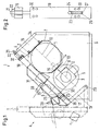
- a roller arrangement 1 in the present case a compact calender, has an upper roller 2 and a lower one Roll up 3.
- the upper roller 2 has a bearing housing 4 on.
- the lower roller 3 has a bearing housing 5. Only a single side of the roller arrangement is shown 1. It is obvious that the opposite Side of the roller arrangement accordingly is trained.
- the bearing housings 4, 5 are arranged in a stand 6, a first recess 7 for the first bearing housing 4 of the upper roller 2 and a second recess 8 for the bearing housing 5 of the lower roller 3.
- the recesses 7, 8 are to a top 9 of the Stand 6 open towards the vertical with an angle of about 45 °.
- a level 10 is about parallel to that Top 9 in which the Axes 11 of the upper roller 2 and 12 of the lower roller 3 are arranged.
- a nip 13 is formed between the two rollers 2, 3, through which a web, not shown, for example, a paper web can to get there with pressure and possibly also increased Pressure to be applied.
- a web not shown, for example, a paper web can to get there with pressure and possibly also increased Pressure to be applied.
- For pressurization has the upper roller 2 shown schematically Pressure elements 14, which are distributed in the axial direction are arranged over the length of the upper roller 2.
- the stand 6 is E-shaped, i.e. he points an upper leg 15, a middle leg 16 and a lower leg 17, the middle Leg 16 relative to the other two legs 15, 17 is shortened.
- the legs 15, 16 delimit the recess 7 and the legs 16, 17 delimit the recess 8th.
- the tie rod 18 is L-shaped. It has a thigh at its lower end 19 on the pivot 6 on the stand 6th is pivotally attached. The tie rod 18 can therefore the position shown in solid lines in be swiveled a position that is dash-dotted is shown in Fig. 1.
- the tie rod 18 has a threaded section at its upper end 21 on which a nut 22 is screwed which is on the upper leg 15 of the stand 6th is applied.
- the stand 6 has one on the lower leg 17 the top 9 protruding projection 23, which in a slot 24 engages in the tie rod 18 when the tie rod 18 in the in Fig. 1 with solid lines shown clamping position is.
- the lead 23 has a rounded top 25 and one extending vertically to the top 9 of the stand 6 rear flank 26 on which an edge 27 of the Slot 24 comes to rest when the nut 22 is tightened becomes. The tensile forces exerted by the tie rod 18 are so over the acting on the edge 26 Edge 27 and that on the upper leg 15 of the stand 6 acting mother 22 applied.
- a number of additional units are attached to the tie rod 18 namely (based on the representation of the 1 from left to right) a tee knife 28, a spreader roller 29, a threading aid 30, for example in the form of a "fibron" band, and one Moisture application device 31, for example in Shape of a steam box or a steam spray tube.
- the tie rod 18 is with an additional attachment the stand 6 connected.
- the additional fastening is formed through a first group of screws or bolts 32, the tie rod at the top of the stand 6 18 connect to the leg 15, and by a second Group of screws or bolts 33 at the bottom of the stand 6 the tie rod 18 with the lower Connect leg 17.
- the screws 32, 33 also place the tie rod 18 on the top 9 of the stand 6 firmly. However, they serve not primarily to add more pulling forces take. Above all, they serve a tendency to vibrate to suppress the tie rod 18.
- the tie rod 18 mainly forms in a tensioned state vibrating structure by external or internal Vibrations can be stimulated, for example by unbalance of the rollers 2, 3. This Vibrations could possibly have a negative effect the additional units 28-31 impact. Through the screws 32, 33 such vibration is prevented or at least heavily subdued. This is especially true for an additional unit 28 in the area of the screws 33 is arranged. There the tie rod 18 swings practically not at all.
- the bearing housing 4 of the upper roller 2 and the upper leg 15 of the stand 6 are pressure elements 34 arranged, the bearing housing 4 opposite the stand 6 brace. If the pressure elements 34, for example be operated hydraulically or pneumatically can be pressurized, then the bearing housing 4 set in stand 6. Conversely, easily remove the bearing housing 4 from the stand 6, when the pressure elements 34 have been released.
- the tie rod 18 locks the bearing housing 4 in the stand 6, i.e. in the in Fig. 1 with solid lines shown position of the tie rod 18 is the tie rod 18 on the top (side parallel to the top 9 of the stand 6) of the bearing housing 4 and prevents thus that the bearing housing 4 from the Stand 6 can move out.
- tie rod 18 instead of the one-piece tie rod 18 shown it is of course also possible to have a two or more part
- tie rods for example in addition fixed to the middle leg 16 of the stand 6 can be. In this case, it might make sense the middle leg 16 to the top 9 of the stand 6 extend.
- the tie rod 18 ensures a closed Power flow around the rollers 2, 3. He avoids one Spreading the legs 15, 17 of the stand 6, secures the bearing housing 4 of the upper roller 2 and carries the additional units 28-31.
- the tie rod 18 on its lower attachment 20 on Stand 6 is pivotable, need to move the Additional units 28-31 applied only relatively small forces become.
- the additional units 28-31 must be in the Principle can only be raised slightly until they are at the pivoting movement of the tie rod 18 the apex their circular movement.
- the tie rod can be shown in dash-dotted lines 18 can simply be parked, for example on the floor or on a floor, not shown Attack.
Landscapes
- Engineering & Computer Science (AREA)
- General Engineering & Computer Science (AREA)
- Mechanical Engineering (AREA)
- Paper (AREA)
- Treatment Of Fiber Materials (AREA)
- Spinning Or Twisting Of Yarns (AREA)
- Rollers For Roller Conveyors For Transfer (AREA)
- Soil Working Implements (AREA)
- Massaging Devices (AREA)
Abstract
Description
- Fig. 1
- eine schematische Seitenansicht einer Walzenanordnung und
- Fig. 2
- eine Vorderansicht auf einen Zuganker.
Claims (13)
- Walzenanordnung mit mindestens einer Walze, einem Ständer, in dem die Walze gelagert ist, und einem Zuganker, der am Ständer befestigt ist, dadurch gekennzeichnet, daß am Zuganker (18) mindestens ein Zusatzaggregat (28-31) befestigt ist, das durch eine Bewegung des Zugankers (18) verlagerbar ist.
- Anordnung nach Anspruch 1, dadurch gekennzeichnet, daß der Zuganker mit einem Ende schwenkbar am Ständer befestigt ist.
- Anordnung nach Anspruch 1 oder 2, dadurch gekennzeichnet, daß mindestens zwei Walzen (2, 3) im Ständer angeordnet sind und der Zuganker (18) so am Ständer (6) befestigt ist, daß sich ein geschlossener Kraftfluß durch den Ständer (6) und den Zuganker (18) um die Walzen (2, 3) herum ergibt.
- Anordnung nach Anspruch 3, dadurch gekennzeichnet, daß der Ständer eine zur Vertikalen geneigte Oberseite (9) aufweist, im wesentlichen parallel zu der eine durch die Achsen (11, 12) der Walzen (2, 3) bestimmte Ebene (10) angeordnet ist, und der Zuganker (18) an der Oberseite (9) angeordnet ist.
- Anordnung nach einem der Ansprüche 1 bis 4, dadurch gekennzeichnet, daß der Zuganker (18) am unteren Ende mit dem Ständer (6) schwenkbar verbunden ist.
- Anordnung nach einem der Ansprüche 1 bis 5, dadurch gekennzeichnet, daß der Zuganker (18) in eine Winkelstellung verschwenkbar ist, in der eine Ausbauöffnung für die Walze (2, 3) aus dem Ständer (6) freigegeben ist.
- Anordnung nach Anspruch 6, dadurch gekennzeichnet, daß der Zuganker (18) um mindestens 30° verschwenkbar ist.
- Anordnung nach einem der Ansprüche 1 bis 7, dadurch gekennzeichnet, daß der Zuganker (18) einen winklig abstehenden Schenkel (19) aufweist, dessen Ende mit dem Ständer (6) schwenkbar verbunden ist.
- Anordnung nach einem der Ansprüche 1 bis 8, dadurch gekennzeichnet, daß der Zuganker (18) eine Öffnung (24) aufweist, in die ein Vorsprung (23) des Ständers (6) eingreift, wenn das andere Ende des Zugankers (18) am Ständer (6) festgelegt ist, wobei zwischen dem Vorsprung (23) und einer Begrenzungswand (27) der Öffnung (24) eine auf Druck belastbare Verbindung (26, 27) geschaffen ist.
- Anordnung nach Anspruch 9, dadurch gekennzeichnet, daß die Öffnung (24) schlitzartig und der Vorsprung (23) länglich ausgebildet sind.
- Anordnung nach einem der Ansprüche 8 bis 10, dadurch gekennzeichnet, daß der Zuganker (18) am Ständer (6) eine Zusatzbefestigung (32, 33) aufweist.
- Anordnung nach Anspruch 11, dadurch gekennzeichnet, daß mindestens ein Zusatzaggregat (28) im Bereich der Zusatzbefestigung (33) angeordnet ist.
- Anordnung nach einem der Ansprüche 1 bis 12, dadurch gekennzeichnet, daß mindestens eine Walze (2, 3) in einem Lagergehäuse (4, 5) gelagert ist, das in einer Ausnehmung (7, 8) des Ständers (6) angeordnet und mit Hilfe von Druckelementen (34) mit dem Ständer (6) verspannt ist.
Applications Claiming Priority (2)
| Application Number | Priority Date | Filing Date | Title |
|---|---|---|---|
| DE10249948 | 2002-10-26 | ||
| DE10249948A DE10249948A1 (de) | 2002-10-26 | 2002-10-26 | Walzenanordnung |
Publications (3)
| Publication Number | Publication Date |
|---|---|
| EP1416176A2 true EP1416176A2 (de) | 2004-05-06 |
| EP1416176A3 EP1416176A3 (de) | 2005-09-14 |
| EP1416176B1 EP1416176B1 (de) | 2007-09-19 |
Family
ID=32087214
Family Applications (1)
| Application Number | Title | Priority Date | Filing Date |
|---|---|---|---|
| EP03021593A Expired - Lifetime EP1416176B1 (de) | 2002-10-26 | 2003-09-25 | Walzenanordnung mit schwenkbarem Zuganker |
Country Status (3)
| Country | Link |
|---|---|
| EP (1) | EP1416176B1 (de) |
| AT (1) | ATE373783T1 (de) |
| DE (2) | DE10249948A1 (de) |
Cited By (7)
| Publication number | Priority date | Publication date | Assignee | Title |
|---|---|---|---|---|
| EP1717368A1 (de) * | 2005-04-30 | 2006-11-02 | Voith Patent GmbH | Kalander |
| EP1739230A1 (de) * | 2005-07-01 | 2007-01-03 | Voith Patent GmbH | Kalander |
| EP1777343A1 (de) * | 2005-10-19 | 2007-04-25 | Voith Patent GmbH | Kalander |
| DE102007000751A1 (de) | 2007-09-20 | 2009-04-09 | Voith Patent Gmbh | Kalander |
| CN106001115A (zh) * | 2016-06-12 | 2016-10-12 | 河北德乐机械科技股份有限公司 | 一种轧辊交错的电池极片轧制设备 |
| CN107470365A (zh) * | 2016-06-12 | 2017-12-15 | 河北德乐机械科技股份有限公司 | 合理轴承游隙的电池极片轧制设备 |
| CN105921517B (zh) * | 2016-06-12 | 2018-08-14 | 河北德乐机械科技股份有限公司 | 一种电池极片轧制设备 |
Family Cites Families (16)
| Publication number | Priority date | Publication date | Assignee | Title |
|---|---|---|---|---|
| DE45312C (de) * | 1900-01-01 | TH. moewes in Berlin | Einstellvorrichtung für die Zapfen von Druckwalzen | |
| BE337630A (de) * | 1925-12-31 | |||
| DE488962C (de) * | 1928-08-10 | 1930-01-11 | Harburger Eisen Und Bronzewerk | Kalander zur Verarbeitung von Gummi oder aehnlichem Material |
| US2138397A (en) * | 1935-10-18 | 1938-11-29 | Hunter James Machine Co | Compression roll |
| US2364443A (en) * | 1940-11-07 | 1944-12-05 | Beloit Iron Works | Roll actuating mechanism |
| US2601793A (en) * | 1947-04-23 | 1952-07-01 | Erwin Loewy | Rolling mill |
| US2785021A (en) * | 1954-07-06 | 1957-03-12 | Farrel Birmingham Co Inc | Roll-positioning device for mills and calenders |
| US2932185A (en) * | 1958-05-13 | 1960-04-12 | Chas H Stehling Company | Machine for preparing hides for tanning |
| US3111894A (en) * | 1962-04-17 | 1963-11-26 | West Virginia Pulp & Paper Co | Calender vibration eliminator |
| CH619157A5 (de) * | 1976-07-16 | 1980-09-15 | Buehler Ag Geb | |
| DE3942452A1 (de) * | 1989-12-22 | 1991-06-27 | Schloemann Siemag Ag | Ermittlung der federkennlinie eines vor- und fertiggeruestes |
| DE4103620C1 (de) * | 1991-02-07 | 1992-02-27 | Sulzer-Escher Wyss Gmbh, 7980 Ravensburg, De | |
| DE4213472C2 (de) * | 1992-04-24 | 1994-05-26 | Heidelberger Druckmasch Ag | Vorrichtung zum Fördern flexibler Druckformen |
| FI101633B (fi) * | 1994-02-04 | 1998-07-31 | Valmet Paper Machinery Inc | Pitkänippitelojen välinen kytkentärakenne ja menetelmä pitkänippiteloj en yhteenliittämisessä |
| DE29520194U1 (de) * | 1995-12-20 | 1996-02-08 | Voith Sulzer Finishing Gmbh | Walzenanordnung |
| DE19856517C2 (de) * | 1998-12-08 | 2001-02-15 | Voith Paper Patent Gmbh | Vorrichtung zum Walzenaustausch bei einem Kalander |
-
2002
- 2002-10-26 DE DE10249948A patent/DE10249948A1/de not_active Withdrawn
-
2003
- 2003-09-25 AT AT03021593T patent/ATE373783T1/de active
- 2003-09-25 DE DE50308208T patent/DE50308208D1/de not_active Expired - Lifetime
- 2003-09-25 EP EP03021593A patent/EP1416176B1/de not_active Expired - Lifetime
Cited By (8)
| Publication number | Priority date | Publication date | Assignee | Title |
|---|---|---|---|---|
| EP1717368A1 (de) * | 2005-04-30 | 2006-11-02 | Voith Patent GmbH | Kalander |
| EP1739230A1 (de) * | 2005-07-01 | 2007-01-03 | Voith Patent GmbH | Kalander |
| EP1777343A1 (de) * | 2005-10-19 | 2007-04-25 | Voith Patent GmbH | Kalander |
| DE102007000751A1 (de) | 2007-09-20 | 2009-04-09 | Voith Patent Gmbh | Kalander |
| CN106001115A (zh) * | 2016-06-12 | 2016-10-12 | 河北德乐机械科技股份有限公司 | 一种轧辊交错的电池极片轧制设备 |
| CN107470365A (zh) * | 2016-06-12 | 2017-12-15 | 河北德乐机械科技股份有限公司 | 合理轴承游隙的电池极片轧制设备 |
| CN105921517B (zh) * | 2016-06-12 | 2018-08-14 | 河北德乐机械科技股份有限公司 | 一种电池极片轧制设备 |
| CN107470365B (zh) * | 2016-06-12 | 2019-09-27 | 河北德乐机械科技股份有限公司 | 合理轴承游隙的电池极片轧制设备 |
Also Published As
| Publication number | Publication date |
|---|---|
| DE10249948A1 (de) | 2004-05-13 |
| EP1416176A3 (de) | 2005-09-14 |
| EP1416176B1 (de) | 2007-09-19 |
| ATE373783T1 (de) | 2007-10-15 |
| DE50308208D1 (de) | 2007-10-31 |
Similar Documents
| Publication | Publication Date | Title |
|---|---|---|
| DE10240039A1 (de) | Öffenbare Klappe, insbesondere Rauchgas-Abzugsklappe und Öffnungs-Mechanismus hierfür | |
| EP1416176B1 (de) | Walzenanordnung mit schwenkbarem Zuganker | |
| DE102007007564B4 (de) | Hochwasserschutzvorrichtung | |
| DE102010004771B3 (de) | Türband für Aluminiumtüren | |
| EP1842970B1 (de) | Anbauplatte für Schnellwechselvorrichtung | |
| AT504559B1 (de) | Hochwasserschutzvorrichtung | |
| DE2019352A1 (de) | Oberwalzen- Trag- und Belastungsvorrichtungen fuer Spinnereimaschinen-Streckwerke | |
| EP0118812B1 (de) | Mehrwalzengerüst | |
| EP3540136A1 (de) | Wandmontagevorrichtung | |
| DE102013220854A1 (de) | Schalung für den Betonbau | |
| DE202012002283U1 (de) | Vorrichtung zum Austauschen eines flexiblen Mantels, Bands oder Siebs | |
| DE102006052664A1 (de) | Vorrichtung zum Befestigen von Tragkonstruktionen an Gebäudewänden | |
| EP0829567B1 (de) | Waschmaschine mit einem Bausatz zur Transportsicherung | |
| DE202017104471U1 (de) | Vorrichtung zum Herauspressen eines vertikalen Trägers einer Trägerbohlwand aus dem Erdreich | |
| DE10341229B4 (de) | Leitwalze | |
| DE19814139C2 (de) | Stützenschalung für Betonstützen | |
| AT514366A2 (de) | Schnellverriegelbare hubeinrichtung | |
| DE8902948U1 (de) | Vorrichtung zum schalldämpfenden Befestigen von Rohrleitungen | |
| DE2150950C3 (de) | Kupplung fur Betonschalungselemente | |
| DE2851739C2 (de) | Schwungradbefestigung einer Spindelschlagpresse | |
| DE102007000751A1 (de) | Kalander | |
| EP2735370A1 (de) | Schleißteilwechselvorrichtung | |
| DE20103899U1 (de) | Pressvorrichtung | |
| EP2316326A1 (de) | Moppresse | |
| DE29608145U1 (de) | Vorrichtung zum Befestigen von biegsamen Druckplatten |
Legal Events
| Date | Code | Title | Description |
|---|---|---|---|
| PUAI | Public reference made under article 153(3) epc to a published international application that has entered the european phase |
Free format text: ORIGINAL CODE: 0009012 |
|
| AK | Designated contracting states |
Kind code of ref document: A2 Designated state(s): AT BE BG CH CY CZ DE DK EE ES FI FR GB GR HU IE IT LI LU MC NL PT RO SE SI SK TR |
|
| AX | Request for extension of the european patent |
Extension state: AL LT LV MK |
|
| PUAL | Search report despatched |
Free format text: ORIGINAL CODE: 0009013 |
|
| AK | Designated contracting states |
Kind code of ref document: A3 Designated state(s): AT BE BG CH CY CZ DE DK EE ES FI FR GB GR HU IE IT LI LU MC NL PT RO SE SI SK TR |
|
| AX | Request for extension of the european patent |
Extension state: AL LT LV MK |
|
| 17P | Request for examination filed |
Effective date: 20050810 |
|
| AKX | Designation fees paid |
Designated state(s): AT DE FI SE |
|
| RAP1 | Party data changed (applicant data changed or rights of an application transferred) |
Owner name: VOITH PATENT GMBH |
|
| GRAP | Despatch of communication of intention to grant a patent |
Free format text: ORIGINAL CODE: EPIDOSNIGR1 |
|
| GRAS | Grant fee paid |
Free format text: ORIGINAL CODE: EPIDOSNIGR3 |
|
| GRAA | (expected) grant |
Free format text: ORIGINAL CODE: 0009210 |
|
| AK | Designated contracting states |
Kind code of ref document: B1 Designated state(s): AT DE FI SE |
|
| REF | Corresponds to: |
Ref document number: 50308208 Country of ref document: DE Date of ref document: 20071031 Kind code of ref document: P |
|
| REG | Reference to a national code |
Ref country code: SE Ref legal event code: TRGR |
|
| PLBE | No opposition filed within time limit |
Free format text: ORIGINAL CODE: 0009261 |
|
| STAA | Information on the status of an ep patent application or granted ep patent |
Free format text: STATUS: NO OPPOSITION FILED WITHIN TIME LIMIT |
|
| 26N | No opposition filed |
Effective date: 20080620 |
|
| PGFP | Annual fee paid to national office [announced via postgrant information from national office to epo] |
Ref country code: SE Payment date: 20110923 Year of fee payment: 9 |
|
| PG25 | Lapsed in a contracting state [announced via postgrant information from national office to epo] |
Ref country code: SE Free format text: LAPSE BECAUSE OF NON-PAYMENT OF DUE FEES Effective date: 20120926 |
|
| REG | Reference to a national code |
Ref country code: SE Ref legal event code: EUG |
|
| PGFP | Annual fee paid to national office [announced via postgrant information from national office to epo] |
Ref country code: DE Payment date: 20140922 Year of fee payment: 12 Ref country code: FI Payment date: 20140911 Year of fee payment: 12 |
|
| PGFP | Annual fee paid to national office [announced via postgrant information from national office to epo] |
Ref country code: AT Payment date: 20140911 Year of fee payment: 12 |
|
| REG | Reference to a national code |
Ref country code: DE Ref legal event code: R119 Ref document number: 50308208 Country of ref document: DE |
|
| REG | Reference to a national code |
Ref country code: AT Ref legal event code: MM01 Ref document number: 373783 Country of ref document: AT Kind code of ref document: T Effective date: 20150925 |
|
| PG25 | Lapsed in a contracting state [announced via postgrant information from national office to epo] |
Ref country code: FI Free format text: LAPSE BECAUSE OF NON-PAYMENT OF DUE FEES Effective date: 20150925 |
|
| PG25 | Lapsed in a contracting state [announced via postgrant information from national office to epo] |
Ref country code: DE Free format text: LAPSE BECAUSE OF NON-PAYMENT OF DUE FEES Effective date: 20160401 |
|
| PG25 | Lapsed in a contracting state [announced via postgrant information from national office to epo] |
Ref country code: AT Free format text: LAPSE BECAUSE OF NON-PAYMENT OF DUE FEES Effective date: 20150925 |