EP1413519A1 - Antriebseinrichtung für ein Umreifungsgerät - Google Patents
Antriebseinrichtung für ein Umreifungsgerät Download PDFInfo
- Publication number
- EP1413519A1 EP1413519A1 EP03405745A EP03405745A EP1413519A1 EP 1413519 A1 EP1413519 A1 EP 1413519A1 EP 03405745 A EP03405745 A EP 03405745A EP 03405745 A EP03405745 A EP 03405745A EP 1413519 A1 EP1413519 A1 EP 1413519A1
- Authority
- EP
- European Patent Office
- Prior art keywords
- strapping
- rotation
- motor
- drive
- drive device
- Prior art date
- Legal status (The legal status is an assumption and is not a legal conclusion. Google has not performed a legal analysis and makes no representation as to the accuracy of the status listed.)
- Granted
Links
- 238000003466 welding Methods 0.000 claims abstract description 21
- 230000005540 biological transmission Effects 0.000 claims description 15
- 238000005520 cutting process Methods 0.000 claims description 4
- 238000000034 method Methods 0.000 description 5
- 229910000831 Steel Inorganic materials 0.000 description 1
- 238000001816 cooling Methods 0.000 description 1
- 230000001419 dependent effect Effects 0.000 description 1
- 238000004806 packaging method and process Methods 0.000 description 1
- 238000003825 pressing Methods 0.000 description 1
- 238000005096 rolling process Methods 0.000 description 1
- 238000010079 rubber tapping Methods 0.000 description 1
- 238000000926 separation method Methods 0.000 description 1
- 239000010959 steel Substances 0.000 description 1
Images


Classifications
-
- B—PERFORMING OPERATIONS; TRANSPORTING
- B65—CONVEYING; PACKING; STORING; HANDLING THIN OR FILAMENTARY MATERIAL
- B65B—MACHINES, APPARATUS OR DEVICES FOR, OR METHODS OF, PACKAGING ARTICLES OR MATERIALS; UNPACKING
- B65B13/00—Bundling articles
- B65B13/18—Details of, or auxiliary devices used in, bundling machines or bundling tools
- B65B13/185—Details of tools
- B65B13/187—Motor means
Definitions
- the invention relates to a drive device of a portable strapping device, which is provided for strapping packaged goods with a strap, the drive device for this purpose having a motor, a gear and at least two functional units, such as a tensioning device, a welding device, a cutting device or the like, for acting on a band is provided, and the motor can be operatively connected to at least one of the functional units by means of a transmission.
- the invention also relates to a battery-operated portable, mobile strapping device, as is reproduced in the preamble of claim 8.
- Strapping devices have long been known with which a tensioned strap loop can be placed around packaged goods. This is done especially for packaging and transport purposes.
- the invention relates primarily to portable, mobile, i.e. non-stationary and permanently installed strapping tools, which are preferably electrically driven and are provided with a mains-independent power supply, such as an accumulator. With such strapping devices, a user can strap packaged goods at any location with a steel band.
- Such devices are used for strapping packaged goods in particular with a plastic strap.
- the strapping device is arranged on the packaged goods, a strap loop is placed around the packaged goods and inserted into the strapping device.
- the end of the strap and the second end of the strap, which is still to be separated, are then arranged in the strapping device.
- a strap tension is then applied to the strap by means of a first functional unit, namely the tensioning device of the strapping device.
- a tensioning wheel is rotated by a motor.
- a frictional connection of the tensioning wheel with one of the belt layers reduces the circumferential length of the belt loop.
- the belt loop then lies on the packaged goods with an at least approximately predetermined belt tension.
- the strapping process is terminated by a subsequent welding process of two layers of tape lying one above the other in sections and a separation of the tape loop from the tape supply roll.
- the welding process is carried out by means of a second functional unit, namely a welding unit of the strapping tool.
- a rotary drive movement is generally transformed into a translatory, oscillating movement of a welding shoe.
- the welding shoe presses against one of two superimposed layers of (plastic) strips, which are heated up and welded together.
- Both the clamping device and the welding device are usually driven by rotary electric motors.
- a high weight can also mean a high energy loss - required per strapping. This is the case if, due to a large number of moving components, high friction and / or inertia forces arise which have to be overcome. If the amount of energy required per strapping can be reduced, this always leads to an increase in the number of straps that can be achieved per battery charge.
- the invention is therefore based on the object of providing a strapping device which is as light as possible with high functional reliability and has the advantages mentioned with regard to the transmission function of the drive.
- this object is achieved by only one motor, provided for the operative connection with at least two functional units, according to claim 1.
- One motor should preferably be drivable in two directions of rotation, the motor being operatively connected in one of the two directions of rotation to a first functional unit and in the other direction of rotation to a second functional unit.
- the invention therefore provides for driving two or more functional units with only one motor.
- Important functional units in strapping devices are the tensioning device and the welding device, which are used one after the other when generating a strapping. It can therefore be expedient for the motor to be operatively connected to the first functional unit in one of the directions of rotation and at the same time to be rotationally decoupled from the second functional unit and to be operatively connected to the second functional unit in the other direction of rotation but to be rotationally decoupled from the first functional unit.
- This measure contributes in particular to a high level of functional reliability of the strapping device drive device according to the invention, since it is solely determined by the direction of rotation of the motor which functional unit becomes active. Complicated and defect-prone complex circuits can be omitted.
- no further manipulation or adjustment has to be carried out in order to put the individual functional units ready for use.
- one or two switches or buttons can be provided, for example.
- the transmission means has a transmission which provides different speeds for tapping by one of the functional units in each case at two locations that are spatially separated from one another.
- the gearbox can thus already provide the required speed for all functional units to be driven by the one motor. This can also contribute to simplifying the design effort and thus increasing the functional reliability. Neither adjustments nor changes or a switching process of components of the drive device or of the strapping device which are located behind the motor in the direction of force flow are necessary.
- the transmission means will have a freewheel which provides a rotationally fixed connection only in one direction of rotation and thereby transmits the motor drive movement. Two such freewheels are provided, the two freewheels only passing on the motor drive movement in opposite directions of rotation.
- a cutting device can also be driven by the motor.
- the battery-operated strapping device 1 shown in FIG. 1 is an example of generic strapping devices to which the invention is directed.
- the strapping device 1 is provided with a housing 2 into which a handle for transporting and handling the strapping device is integrated.
- an exchangeable accumulator 3 is detachably attached to the strapping device 1 as a power supply by means of a snap connection.
- the strapping device 1 has a base plate 4, with the preferably flat underside 4a of which the strapping device is placed on a packaged item to be strapped.
- a tensioning device 5 above the base plate with a tensioning wheel 6 hidden by the housing in the illustration of FIG. 1 intended.
- a closing device designed as a welding device 8 is arranged behind it in the tensioning direction 7. Lying in line with the tensioning device 5 and the welding device 8, a cutting device 9 is connected to the welding device when viewed in the tensioning direction 7.
- the strapping device 1 has a plurality of actuable backstops (not shown) which are known per se and by means of which the strap or strap sections can be detachably fixed in the strapping device 1.
- the strapping device 1 In order to strap a packaged good, the strapping device 1 should be arranged with its base plate 4 on the packaged good.
- a belt loop loosely guided around the packaged goods can be inserted between the base plate 4 and the tensioning wheel 6 with a section in which two belt layers are arranged one above the other.
- a distance between the tensioning wheel 6 and a tooth plate 10 lying opposite this is then reduced, so that the lower band layer bears against the tooth plate 10 arranged in the base plate 4 and the tensioning wheel 6 bears against the upper band layer.
- the tooth plate 10 can be raised, for example.
- the tensioning wheel 6 can then be set in rotation by actuating a tensioning button. Due to friction between the tensioning wheel and the upper layer of tape, the latter is carried along by the tensioning wheel, whereby the circumference of the loop is reduced and the loop lies with a certain band tension on the packaged goods.
- the welding device 8 is then used. For example, by an oscillating movement of a welding shoe 12, the band can be melted to such an extent that after cooling between the two layers of the band, a cohesive connection has arisen.
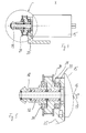
- FIGS. 2 to 5 A possible embodiment of one for generating the movements
- the tensioning and welding device 5, 8 provided according to the invention drive device 14 can be seen from FIGS. 2 to 5.
- the drive device 14 has a direct current electric motor 15 which generates a drive movement at a nominal speed of 8000 rpm, for example.
- the motor 15 can provide the drive movement with two different directions of rotation 16, 17. Furthermore, the motor 15 is monitored and controlled by an electronic control, not shown in detail.
- a toothed pinion designed as a bevel pinion 19 is arranged on a shaft 18 of the motor. Between the motor 15 and the bevel pinion 19 there is also a toothed pulley 20 of a belt drive 21 on the shaft 18 of the motor. Both the bevel pinion 19 and the toothed disk 20 are part of a drive side of a transmission 22 of the drive device according to the invention, which is connected downstream of the electric motor.
- the bevel pinion located on the end face of the shaft 18 engages in a bevel gear 26 arranged on a shaft 25 of the tensioning wheel.
- the shaft 18 of the motor and the shaft 25 of the tensioning wheel form an angle of 90 °.
- the bevel gear 26 thus located on the output side of the transmission 22 has teeth with 42 teeth, while the bevel pinion 19 is provided with 17 teeth.
- the bevel pinion 19 and the bevel gear 26 thus form a reduction in the rotational movement of the motor on the tensioning wheel.
- the rotational movement of the toothed pulley 20 provided on the drive side is transmitted via an endless toothed belt 27 to a toothed pulley 28 on the driven side.
- the output-side toothed disc 28 is arranged on a shaft 29 of a further gear 30, with which the rotational movement of the Motor is converted into an oscillating movement of the welding shoe 12.
- Embodiments for the latter transmission are known in many different ways, which is why there is no need to go into them in detail.
- the driving toothed disk 20 has a toothing with 37 teeth compared to 13 teeth of the driven toothed disk 28, the two toothed disks are part of a translation of the drive movement of the motor.
- both the driving toothed disk 20 and the bevel pinion 19 are each arranged on a sleeve freewheel 31, 32 and connected to it in a rotationally fixed manner.
- loads on the bevel pinion and the toothed disk 20 are derived into a carrier 35 of the drive device via additional ball bearings 33, 34.
- the ball bearing 34 also contributes to the toothed disk being supported on the bevel pinion 19, but can nevertheless be rotated independently of the bevel pinion.
- the sleeve freewheel with bearing HFL 1626 offered by INA Wälzlager Schaeffler oHG, Herzogenaurach (Germany) has been shown, among others. in catalog 306/1991, proved to be suitable.
- Such freewheels only transmit the rotational movement of the shaft to the element mounted on them in one direction of rotation 16, 17 by a positive fit. In the other direction of rotation 16, 17, they act like a conventional rolling element bearing, which allow relative movements between the machine elements to be supported.
- the two freewheels 31, 32 are arranged on the shaft 18 in such a way that in each direction of rotation 16, 17 only one freewheel produces a rotationally fixed connection with either the bevel pinion 19 or the toothed disk 20.
Landscapes
- Engineering & Computer Science (AREA)
- Mechanical Engineering (AREA)
- Basic Packing Technique (AREA)
Abstract
Description
- Die Erfindung betrifft eine Antriebseinrichtung eines tragbaren Umreifungsgerätes, das zur Umreifung von Packgut mit einem Band vorgesehen ist, wobei die Antriebseinrichtung hierzu mit einem Motor, einem Getriebe und zumindest zwei Funktionseinheiten, wie einer Spanneinrichtung, einer Schweisseinrichtung, einer Schneideinrichtung oder dergleichen, zur Einwirkung auf ein Band versehen ist, und der Motor mittels einem Getriebe mit zumindest einer der Funktionseinheiten wirkverbindbar ist. Die Erfindung betrifft zudem ein akkubetriebenes tragbares, mobiles Umreifungsgerät, wie es im Oberbegriff von Anspruch 8 wiedergegeben ist.
- Es sind seit langem Umreifungsgeräte bekannt, mit denen um Packgut eine gespannte Bandschlaufe gelegt werden kann. Dies erfolgt insbesondere zu Verpackungs- und Transportzwecken. Die Erfindung bezieht sich in erster Linie auf tragbare, mobile, d.h. nicht stationäre und fest installierte, Umreifungsgeräte, die vorzugsweise elektrisch angetrieben und mit einer netzunabhängigen Stromversorgung, wie beispielsweise einem Akkumulator, versehen sind. Mit solchen Umreifungsgeräten kann ein Benutzer an beliebigen Orten Packgut mit einem Stahlband umreifen.
- Derartige Geräte werden zur Umreifung von Packgut insbesondere mit einem Kunststoffband verwendet. Hierzu wird das Umreifungsgerät auf dem Packgut angeordnet, eine Bandschlaufe um das Packgut gegeben und in das Umreifungsgerät eingelegt. Das Bandende sowie das noch abzutrennende zweite Ende der Bandschlaufe sind dann im Umreifungsgerät angeordnet. Anschliessend wird mittels einer ersten Funktionseinheit, nämlich der Spanneinrichtung des Umreifungsgerätes, auf das Band eine Bandspannung aufgebracht. Hierzu wird ein Spannrad mit einem Motor in eine Drehbewegung versetzt. Durch einen Reibschluss des Spannrades mit einer der Bandlagen wird eine Verringerung der Umfangslänge der Bandschlaufe erzielt.
- Am Ende des Spannvorgangs liegt dann die Bandschlaufe mit einer zumindest näherungsweise vorbestimmten Bandspannung am Packgut an.
- Durch einen nachfolgenden Schweissvorgang zweier abschnittsweise übereinanderliegender Bandlagen und ein Abtrennen der Bandschlaufe von der Bandvorratsrolle wird der Umreifungsvorgang beendet. Der Schweissvorgang wird hierbei mittels einer zweiten Funktionseinheit, nämlich einer Schweisseinheit des Umreifungsgerätes durchgeführt. Hierzu wird in der Regel eine rotatorische Antriebsbewegung in eine translatorische oszillierende Bewegung eines Schweissschuhs transformiert. Der Schweissschuh drückt hierbei gegen eine von zwei aufeinanderliegenden Lagen von (Kunststoff-) Bändern, die dadurch erhitzt werden und miteinander verschweissen. Sowohl die Spanneinrichtung als auch die Schweisseinrichtung werden üblicherweise mit rotativen elektrischen Motoren angetrieben.
- Bei solchen mobilen Umreifungsgeräten ist man stets bestrebt, Gewicht zu sparen, um die Handhabbarkeit und Transportierbarkeit der Geräte zu verbessern. Ein hohes Gewicht kann zu einer Kopflastigkeit des Gerätes führen, was dessen Handhabung erschwert. Ausserdem wird es als unangenehm empfunden, wenn ein Gerät mit hohem Gewicht von einer Einsatzstelle zur nächsten - in der Regel von Hand - transportiert werden muss.
- Schliesslich kann ein hohes Gewicht auch eine hohe - pro Umreifung benötigte - Verlustenergie bedeuten. Dies trifft dann zu, wenn aufgrund von einer Vielzahl von bewegten Bauteilen hohe Reib- und/oder Trägheitskräfte entstehen, die überwunden werden müssen. Kann die pro Umreifung benötigte Energiemenge reduziert werden, so führt dies zu einer stets angestrebten Steigerung der pro Akkumulatorladung erzielbaren Anzahl an Umreifungen.
- Aus der US-A-6 003 578 ist ein Antrieb bekannt, der der Gattung gemäss der oben beschriebenen Problemstellung entspricht und grundsätzlich schon geeignet zu sein scheint, einen Teil der Probleme zu überwinden. Ebenso ist ein entsprechender Antrieb aus der US-A-4 313 779 bekannt. Diese Vorrichtungen gilt es zu verbessern, wobei insbesondere die Übertragungsfunktion des Antriebs verbessert werden soll.
- Der Erfindung liegt deshalb die Aufgabe zugrunde, ein Umreifungsgerät zu schaffen, das bei hoher Funktionssicherheit möglichst leicht ist und die genannten Vorteile bezüglich der Übertragungsfunktion des Antriebs aufweist.
- Diese Aufgabe wird bei einer Antriebseinrichtung der eingangs genannten Art durch lediglich einen, zur Wirkverbindung mit zumindest zwei Funktionseinheiten vorgesehenen, Motor nach Anspruch 1 gelöst. Der eine Motor sollte vorzugsweise in zwei Drehrichtungen antreibbar sein, wobei der Motor in einer der beiden Drehrichtungen mit einer ersten Funktionseinheit und in der anderen Drehrichtung mit einer zweiten Funktionseinheit wirkverbunden ist. Erfindungsgemäss ist somit vorgesehen, zwei oder mehr Funktionseinheiten mit lediglich einem Motor anzutreiben.
- Wichtige Funktionseinheiten bei Umreifungsgeräten sind die Spanneinrichtung und die Schweisseinrichtung, die bei der Erzeugung einer Umreifung zeitlich nacheinander zum Einsatz kommen. Es kann deshalb zweckmässig sein, dass der Motor in einer der Drehrichtungen mit der ersten Funktionseinheit wirkverbunden und gleichzeitig mit der zweiten Funktionseinheit rotatorisch entkoppelt ist und in der anderen Drehrichtung mit der zweiten Funktionseinheit wirkverbunden, hingegen mit der ersten Funktionseinheit rotatorisch entkoppelt ist. Diese Massnahme trägt insbesondere zu einer hohen Funktionssicherheit der erfindungsgemässen Umreifungsgerät-Antriebseinrichtung bei, da alleine durch die Drehrichtung des Motors bestimmt ist, welche Funktionseinheit aktiv wird. Komplizierte und defektanfällige aufwendige Schaltungen können entfallen. Ebenso muss ausser einer Vorwahl der Drehrichtung des Motors am Umreifungsgerät keine weitere Manipulation oder Einstellung vorgenommen werden, um die einzelnen Funktionseinheiten in Einsatzbereitschaft zu versetzen. Zur Wahl der Drehrichtung können beispielsweise ein oder zwei Schalter bzw. Tasten vorgesehen sein.
- Es hat sich dabei als vorteilhaft im Sinne der vorliegenden Erfindung erwiesen, wenn das Übertragungsmittel ein Getriebe aufweist, das an zwei örtlich voneinander getrennten Stellen unterschiedliche Drehzahlen zum Abgriff durch jeweils eine der Funktionseinheiten zur Verfügung stellt. Damit kann bereits durch das Getriebe für sämtliche von dem einen Motor anzutreibenden Funktionseinheiten die jeweils erforderliche Drehzahl bereitgestellt werden. Auch dies kann zu einer Vereinfachung des konstruktiven Aufwandes und damit zur Erhöhung der Funktionssicherheit beitragen. Es sind weder Einstellungen noch Veränderungen oder ein Schaltvorgang von Bauelementen der Antriebseinrichtung bzw. des Umreifungsgerätes erforderlich, die in Kraftflussrichtung hinter dem Motor liegen.
- Vorteilhafterweise werden die Übertragungsmittel einen Freilauf aufweisen, der nur in einer Drehrichtung eine drehfeste Verbindung bereitstellt und hierdurch die motorische Antriebsbewegung überträgt. Es sind zwei solcher Freiläufe vorgesehen, wobei die beiden Freiläufe die motorische Antriebsbewegung nur in entgegengesetzte Drehrichtungen weitergeben.
- Selbstverständlich können die genannten Massnahmen auch im Zusammenhang mit anderen Funktionseinheiten als der erwähnten Spanneinrichtung und Schweisseinrichtung eines Umreifungsgerätes vorgesehen sein. So kann beispielsweise anstelle von einer dieser Funktionseinheiten oder aber zusätzlich zu diesen auch eine Schneideinrichtung mit dem Motor angetrieben werden.
- Weitere bevorzugte Ausgestaltungen der Erfindung ergeben sich aus den abhängigen Ansprüchen.
- Die Erfindung wird anhand den in des in den Figuren schematisch dargestellten Ausführungsbeispiels näher erläutert; es zeigen:
- Fig. 1
- ein erfindungsgemässes Umreifungsgerät in einer perspektivischen Darstellung;
- Fig. 2
- das Umreifungsgerät aus Fig. 1 mit abgenommenem Gehäuse in einer perspektivischen Darstellung von oben;
- Fig. 3
- eine erfindungsgemässe Antriebseinrichtung mit einer teilweisen Darstellung von deren Getriebe;
- Fig. 4
- eine Schnittdarstellung entlang der Linie IV - IV aus Fig. 3;
- Fig. 5
- eine Darstellung des Details X aus Fig. 4.
- Das in Fig. 1 gezeigte akkubetriebene Umreifungsgerät 1 ist ein Beispiel für gattungsgemässe Umreifungsgeräte, an die sich die Erfindung richtet. Das Umreifungsgerät 1 ist mit einem Gehäuse 2 versehen, in das ein Griff zum Transport und zur Handhabung des Umreifungsgerätes integriert ist. Am hinteren Ende des Gehäuses 2 ist an dem Umreifungsgerät 1 mittels einer Schnappverbindung ein austauschbarer Akkumulator 3 als Stromversorgung lösbar befestigt.
- Das Umreifungsgerät 1 weist eine Grundplatte 4 auf, mit deren vorzugsweise ebener Unterseite 4a das Umreifungsgerät auf ein zu umreifendes Packgut gestellt wird. Im Bereich des vorderen Endes des Umreifungsgerätes aus Fig. 1 ist oberhalb der Grundplatte eine Spanneinrichtung 5 mit einem in der Darstellung von Fig. 1 durch das Gehäuse verdeckten Spannrad 6 vorgesehen. In Spannrichtung 7 dahinter ist eine als Schweisseinrichtung 8 ausgebildete Verschlusseinrichtung angeordnet. In einer Linie mit der Spanneinrichtung 5 und der Schweisseinrichtung 8 liegend, schliesst sich in Spannrichtung 7 gesehen an die Schweisseinrichtung eine Schneideinrichtung 9 an. Ferner weist das Umreifungsgerät 1 mehrere, an sich bekannte, betätigbare Rücklaufsperren (nicht dargestellt) auf, mit denen das Band bzw. die Bandabschnitte im Umreifungsgerät 1 lösbar fixiert werden können.
- Um ein Packgut zu umreifen, sollte das Umreifungsgerät 1 mit seiner Grundplatte 4 auf dem Packgut angeordnet werden. Eine lose um das Packgut geführte Bandschlaufe kann mit einem Abschnitt, in dem zwei Bandlagen übereinander angeordnet sind, zwischen der Grundplatte 4 und dem Spannrad 6 eingeführt werden. Ein Abstand zwischen dem Spannrad 6 und einer diesem gegenüberliegenden Zahnplatte 10 wird dann verringert, so dass die untere Bandlage gegen die in der Grundplatte 4 angeordnete Zahnplatte 10 und das Spannrad 6 gegen die obere Bandlage anliegt. Um den Abstand zu verändern, kann beispielsweise die Zahnplatte 10 angehoben werden. Anschliessend kann durch Betätigung einer Spanntaste das Spannrad 6 in Rotation versetzt werden. Durch Reibung zwischen dem Spannrad und der oberen Bandlage wird letztere von dem Spannrad mitgenommen, wodurch der Umfang der Schlaufe sich verkleinert und die Schlaufe mit einer gewissen Bandspannung am Packgut anliegt.
- Bei ausreichender Bandspannung kommt dann die Schweisseinrichtung 8 zum Einsatz. Durch beispielsweise eine oszillierende Bewegung eines Schweissschuhs 12, kann das Band soweit angeschmolzen werden, dass nach einer Abkühlung zwischen den beiden Bandlagen eine stoffschlüssige Verbindung entstanden ist.
- Eine mögliche Ausführungsform einer zur Erzeugung der Bewegungen der Spann- und der Schweisseinrichtung 5, 8 vorgesehenen erfindungsgemässe Antriebseinrichtung 14 geht aus den Fig. 2 bis 5 hervor.
- Die Antriebseinrichtung 14 weist einen Gleichstrom-Elektromotor 15 auf, der mit beispielsweise einer Nenndrehzahl von 8000 U/min eine Antriebsbewegung erzeugt. Der Motor 15 kann mit zwei unterschiedlichen Drehrichtungen 16, 17 die Antriebsbewegung bereitstellen. Ferner wird der Motor 15 von einer nicht näher dargestellten elektronischen Steuerung überwacht und gesteuert.
- Auf einer Welle 18 des Motors ist ein als Kegelritzel 19 ausgebildetes Zahnritzel angeordnet. Zwischen dem Motor 15 und dem Kegelritzel 19 befindet sich zudem eine Zahnscheibe 20 eines Riementriebs 21 auf der Welle 18 des Motors. Sowohl das Kegelritzel 19 als auch die Zahnscheibe 20 sind Bestandteil einer Antriebsseite eines dem Elektromotor nachgeschalteten Getriebes 22 der erfindungsgemässen Antriebseinrichtung.
- Das sich an der Stirnseite der Welle 18 befindende Kegelritzel greift in ein auf einer Welle 25 des Spannrades angeordnete Kegelrad 26 ein. Die Welle 18 des Motors und die Welle 25 des Spannrades schliessen hierbei einen Winkel von 90° ein. Das sich somit auf der Abtriebsseite des Getriebes 22 befindende Kegelrad 26 weist eine Verzahnung mit 42 Zähnen auf, während das Kegelritzel 19 mit 17 Zähnen versehen ist. Das Kegelritzel 19 und das Kegelrad 26 bilden somit eine Untersetzung der Rotationsbewegung des Motors auf das Spannrad.
- Die Rotationsbewegung der antriebsseitig vorgesehenen Zahnscheibe 20 wird hingegen über einen Endlos-Zahnriemen 27 auf eine abtriebseitige Zahnscheibe 28 übertragen. Die abtriebseitige Zahnscheibe 28 ist auf einer Welle 29 eines weiteren Getriebes 30 angeordnet, mit dem die Rotationsbewegung des Motors in eine oszillierende Bewegung des Schweissschuhs 12 umgewandelt wird. Ausführungsformen für das letztgenannte Getriebe sind in vielfältiger Weise vorbekannt, weshalb hierauf nicht näher eingegangen werden muss.
- Da die treibende Zahnscheibe 20 eine Verzahnung mit 37 Zähnen gegenüber 13 Zähnen der getriebenen Zahnscheibe 28 aufweist, sind die beiden Zahnscheiben Bestandteil einer Übersetzung der Antriebsbewegung des Motors.
- Wie insbesondere aus den Schnittdarstellungen von Fig. 4 und Fig. 5 hervorgeht, ist sowohl die treibende Zahnscheibe 20 als auch das Kegelritzel 19 jeweils auf einem Hülsenfreilauf 31, 32 angeordnet und mit diesem drehfest verbunden. Über zusätzliche Kugellager 33, 34 werden einerseits Belastungen des Kegelritzels und der Zahnscheibe 20 in einen Träger 35 der Antriebseinrichtung abgeleitet. Andererseits trägt im Ausführungsbeispiel das Kugellager 34 auch dazu bei, dass sich die Zahnscheibe auf dem Kegelritzel 19 abstützt, trotzdem jedoch unabhängig vom Kegelritzel drehen lässt.
- Für das vorliegende Ausführungsbeispiel hat sich beispielsweise der von der Firma INA Wälzlager Schaeffler oHG, Herzogenaurach (Deutschland), angebotene Hülsenfreilauf mit Lagerung HFL 1626, gezeigt u.a. im Katalog 306/1991, als geeignet erwiesen. Derartige Freiläufe geben nur in eine Drehrichtung 16, 17 durch einen Formschluss die Drehbewegung der Welle an das auf ihnen gelagerte Element weiter. In der jeweils anderen Drehrichtung 16, 17 wirken sie wie ein übliches Wälzkörperlager, das Relativbewegungen zwischen den zu lagernden Maschinenelementen zulassen.
- Im vorliegenden Fall sind die beiden Freiläufe 31, 32 so auf der Welle 18 angeordnet, dass in jeder Drehrichtung 16, 17 jeweils nur ein Freilauf eine drehfeste Verbindung mit entweder dem Kegelritzel 19 oder der Zahnscheibe 20 erzeugt.
- Das jeweils andere Bauelement ist dann trotz rotierender Welle 18 ortsfest angeordnet. Je nachdem, in welcher Drehrichtung 16, 17 der Motor 15 die Welle 18 antreibt, gibt somit entweder das Kegelritzel 19 oder die Zahnscheibe 20 die motorische Antriebsbewegung und ein Drehmoment weiter. Die Drehrichtung 16, 17 kann hierbei durch Betätigung einer entsprechenden Taste am Gehäuse vorgewählt werden. Somit kann mit nur einem Motor 15 entweder das Spannrad 6 oder die Schweisseinrichtung 8 in Betrieb genommen werden.
-
- 1
- Umreifungsgerät
- 2
- Gehäuse
- 3
- Akkumulator
- 4
- Grundplatte
- 4a
- Unterseite
- 5
- Spanneinrichtung
- 6
- Spannrad
- 7
- Spannrichtung
- 8
- Schweisseinrichtung
- 9
- Schneideinrichtung
- 10
- Zahnplatte
- 12
- Schweissschuh
- 14
- Antriebseinrichtung
- 15
- Elektromotor
- 16
- erste Drehrichtung
- 17
- zweite Drehrichtung
- 18
- Welle
- 19
- Kegelritzel
- 20
- Zahnscheibe
- 21
- Riementrieb
- 22
- Getriebe
- 25
- Welle (Spannrad)
- 26
- Kegelrad
- 27
- Zahnriemen
- 28
- Zahnscheibe
- 29
- Welle
- 30
- Getriebe
- 31
- Hülsenfreilauf
- 32
- Hülsenfreilauf
- 33
- Kugellager
- 34
- Kugellager
- 35
- Träger
Claims (8)
- Antriebseinrichtung eines tragbaren Umreifungsgerätes, das zur Umreifung von Packgut mit einem Band vorgesehen ist, die Antriebseinrichtung hierzu mit einem Getriebe und zumindest zwei Funktionseinheiten, wie einer Spanneinrichtung, einer Schweisseinrichtung, einer Schneideinrichtung oder dergleichen, zur Einwirkung auf ein Band versehen ist, wobei die Antriebseinrichtung mittels einem Übertragungsmittel mit zumindest einer der Funktionseinheiten wirkverbindbar ist, mit lediglich einem Motor (15), der zur Wirkverbindung mit zumindest zwei Funktionseinheiten vorgesehen ist,
dadurch gekennzeichnet, dass
das Getriebe (22) abtriebsseitig ein Endlos-Hüllglied, insbesondere einen auf einer Riemenscheibe angeordneten Riemen (27) aufweist. - Antriebseinrichtung nach Anspruch 1, dadurch gekennzeichnet, dass der eine Motor (15) in zwei unterschiedliche Drehrichtungen (16, 17) antreibbar ist, wobei der Motor (15) in einer der beiden Drehrichtungen (16, 17) mit einer ersten Funktionseinheit und in der anderen Drehrichtung (16, 17) mit einer zweiten Funktionseinheit wirkverbunden ist.
- Antriebseinrichtung nach Anspruch 2, dadurch gekennzeichnet, dass der Motor (15) in einer der Drehrichtungen (16, 17) mit der ersten Funktionseinheit wirkverbunden und gleichzeitig mit der zweiten Funktionseinheit rotatorisch entkoppelt ist und in der anderen Drehrichtung (16, 17) mit der zweiten Funktionseinheit wirkverbunden, hingegen mit der ersten Funktionseinheit rotatorisch entkoppelt ist.
- Antriebseinrichtung nach einem der Ansprüche 2 oder 3, gekennzeichnet durch eine Freilaufeinrichtung (31, 32) des Getriebes (22), die auf einer Abtriebsseite des Getriebes (22) zwei in Abhängigkeit der Drehrichtung (16, 17) des Motors (15) alternativ zueinander vorgesehene Stellen für einen Drehmomentenabgriff bereitstellt.
- Antriebseinrichtung nach einem der vorhergehenden Ansprüche, dadurch gekennzeichnet, dass das Getriebe (22) Getriebeglieder aufweist, die in einer Drehrichtung (16, 17) die Antriebsbewegung des Motors übersetzen und die andere Drehrichtung untersetzen.
- Tragbares Umreifungsgerät zur Umreifung von Packgut mit einem Umreifungsband, das eine Spanneinrichtung zur Aufbringung einer Zugspannung auf ein Umreifungsband aufweist und mit einer Verbindungseinrichtung versehen ist, mit der zwei Bandlagen eines Umreifungsbandes miteinander verbindbar sind, gekennzeichnet durch eine Antriebseinrichtung (14) nach einem der vorhergehenden Ansprüche.
- Tragbares Umreifungsgerät nach Anspruch 6, dadurch gekennzeichnet, dass mit der Antriebseinrichtung (14) sowohl eine Antriebsbewegung für die Spanneinrichtung (5) als auch eine Antriebsbewegung für die Verbindungseinrichtung (8) erzeugbar ist.
- Tragbares Umreifungsgerät nach einem der Ansprüche 6 oder 7, gekennzeichnet durch einen am Umreifungsgerät lösbar befestigten Akkumulator (3) als elektrische Energiequelle für die Antriebseinrichtung (14).
Applications Claiming Priority (2)
| Application Number | Priority Date | Filing Date | Title |
|---|---|---|---|
| CH17922002 | 2002-10-25 | ||
| CH17922002 | 2002-10-25 |
Publications (2)
| Publication Number | Publication Date |
|---|---|
| EP1413519A1 true EP1413519A1 (de) | 2004-04-28 |
| EP1413519B1 EP1413519B1 (de) | 2007-03-14 |
Family
ID=32046639
Family Applications (1)
| Application Number | Title | Priority Date | Filing Date |
|---|---|---|---|
| EP03405745A Expired - Lifetime EP1413519B1 (de) | 2002-10-25 | 2003-10-16 | Antriebseinrichtung für ein Umreifungsgerät |
Country Status (4)
| Country | Link |
|---|---|
| EP (1) | EP1413519B1 (de) |
| AT (1) | ATE356748T1 (de) |
| DE (1) | DE50306793D1 (de) |
| ES (1) | ES2283737T3 (de) |
Cited By (27)
| Publication number | Priority date | Publication date | Assignee | Title |
|---|---|---|---|---|
| WO2009087216A2 (de) * | 2008-01-11 | 2009-07-16 | Maschinenfabrik Gerd Mosca Ag | Bandantrieb für umreifungsmaschinen |
| WO2009129633A1 (de) * | 2008-04-23 | 2009-10-29 | Orgapack Gmbh | Umreifungsvorrichtung mit einer getriebeeinrichtung |
| WO2009129634A1 (de) * | 2008-04-23 | 2009-10-29 | Orgapack Gmbh | Mobile umreifungsvorrichtung |
| WO2009129635A1 (de) * | 2008-04-23 | 2009-10-29 | Orgapack Gmbh | Umreifungsvorrichtung mit einem energiespeicher |
| WO2009129637A1 (de) * | 2008-04-23 | 2009-10-29 | Orgapack Gmbh | Umreifungsvorrichtung mit einem elektrischen antrieb |
| CN101652287B (zh) * | 2007-02-14 | 2011-12-28 | 奥格派克有限公司 | 打包装置 |
| CN101678903B (zh) * | 2007-07-10 | 2012-02-01 | 伊利诺斯工具制品有限公司 | 两部件捆扎工具 |
| WO2013052446A1 (en) * | 2011-10-04 | 2013-04-11 | Illinois Tool Works Inc. | Sealing tool for strap |
| CN103587762A (zh) * | 2012-08-17 | 2014-02-19 | 上海金汇通创意设计发展股份有限公司 | 用于折包边机的传动机构 |
| US9193486B2 (en) | 2008-04-23 | 2015-11-24 | Signode Industrial Group Llc | Strapping device with a tensioner |
| DE202016102835U1 (de) | 2015-07-08 | 2016-06-08 | LINDER GmbH | Umreifungsvorrichtung zum Sichern eines Packguts |
| DE202015009004U1 (de) | 2015-07-08 | 2016-06-10 | LINDER GmbH | Umreifungsvorrichtung zum Sichern eines Packguts |
| EP3272659A1 (de) | 2016-07-21 | 2018-01-24 | TITAN Umreifungstechnik GmbH & Co.KG | Handumreifungs- und/oder verschlussgerät |
| US9932135B2 (en) | 2012-09-24 | 2018-04-03 | Signode Industrial Group Llc | Strapping device |
| US9994341B2 (en) | 2013-05-05 | 2018-06-12 | Signode Industrial Group Llc | Mobile strapping device having a display means |
| US10220971B2 (en) | 2014-02-10 | 2019-03-05 | Signode Industrial Group Llc | Tensioning device for a strapping device |
| US10227149B2 (en) | 2011-11-14 | 2019-03-12 | Signode Industrial Group Llc | Strapping apparatus |
| USD864688S1 (en) | 2017-03-28 | 2019-10-29 | Signode Industrial Group Llc | Strapping device |
| US10518914B2 (en) | 2008-04-23 | 2019-12-31 | Signode Industrial Group Llc | Strapping device |
| US10577137B2 (en) | 2015-12-09 | 2020-03-03 | Signode Industrial Group Llc | Electrically powered combination hand-held notch-type strapping tool |
| EP3696102A1 (de) * | 2019-02-15 | 2020-08-19 | TITAN Umreifungstechnik GmbH & Co.KG | Umreifungsvorrichtung |
| EP3696103A1 (de) * | 2019-02-15 | 2020-08-19 | TITAN Umreifungstechnik GmbH & Co.KG | Umreifungsvorrichtung für insbesondere stahlbänder |
| WO2021203846A1 (zh) * | 2020-04-09 | 2021-10-14 | 台州市永派包装设备有限公司 | 熔接装置 |
| US11155375B2 (en) | 2017-01-30 | 2021-10-26 | Signode Industrial Group Llc | Strapping apparatus having an actuating element for the tensioning device |
| WO2022052987A1 (zh) * | 2020-09-10 | 2022-03-17 | 宁波欣仪伟业进出口有限公司 | 一种电动捆扎机及一种可充电电池包 |
| US11352153B2 (en) | 2019-05-07 | 2022-06-07 | Signode Industrial Group Llc | Strapping tool |
| RU2790732C1 (ru) * | 2020-04-09 | 2023-02-28 | Тайчжоу Юнпай Пэк Иквипмент Ко., Лтд. | Устройство для сварки плавлением |
Citations (6)
| Publication number | Priority date | Publication date | Assignee | Title |
|---|---|---|---|---|
| US3125326A (en) * | 1964-03-17 | ericsson | ||
| US4313779A (en) | 1979-07-30 | 1982-02-02 | Signode Corporation | All electric friction fusion strapping tool |
| US4820363A (en) * | 1985-01-23 | 1989-04-11 | Strapex Ag | Tensioning and connecting apparatus for connecting overlapping strap ends of synthetic material |
| EP0371290A1 (de) * | 1988-11-29 | 1990-06-06 | Joslyn Corporation | Bandspanngerät |
| EP0510916A1 (de) * | 1991-04-22 | 1992-10-28 | Signode Corporation | Mechanismus zum Umwandeln einer Drehbewegung mit wechselndem Drehsinn in eine einsinnig umlaufende Bewegung |
| US6003578A (en) | 1998-05-04 | 1999-12-21 | Chang; Jeff Chieh Huang | Portable electrical wrapping apparatus |
-
2003
- 2003-10-16 DE DE50306793T patent/DE50306793D1/de not_active Expired - Lifetime
- 2003-10-16 AT AT03405745T patent/ATE356748T1/de not_active IP Right Cessation
- 2003-10-16 ES ES03405745T patent/ES2283737T3/es not_active Expired - Lifetime
- 2003-10-16 EP EP03405745A patent/EP1413519B1/de not_active Expired - Lifetime
Patent Citations (6)
| Publication number | Priority date | Publication date | Assignee | Title |
|---|---|---|---|---|
| US3125326A (en) * | 1964-03-17 | ericsson | ||
| US4313779A (en) | 1979-07-30 | 1982-02-02 | Signode Corporation | All electric friction fusion strapping tool |
| US4820363A (en) * | 1985-01-23 | 1989-04-11 | Strapex Ag | Tensioning and connecting apparatus for connecting overlapping strap ends of synthetic material |
| EP0371290A1 (de) * | 1988-11-29 | 1990-06-06 | Joslyn Corporation | Bandspanngerät |
| EP0510916A1 (de) * | 1991-04-22 | 1992-10-28 | Signode Corporation | Mechanismus zum Umwandeln einer Drehbewegung mit wechselndem Drehsinn in eine einsinnig umlaufende Bewegung |
| US6003578A (en) | 1998-05-04 | 1999-12-21 | Chang; Jeff Chieh Huang | Portable electrical wrapping apparatus |
Cited By (76)
| Publication number | Priority date | Publication date | Assignee | Title |
|---|---|---|---|---|
| US8287672B2 (en) | 2007-02-14 | 2012-10-16 | Illinois Tool Works Inc. | Strapping device |
| CN101652287B (zh) * | 2007-02-14 | 2011-12-28 | 奥格派克有限公司 | 打包装置 |
| CN101678903B (zh) * | 2007-07-10 | 2012-02-01 | 伊利诺斯工具制品有限公司 | 两部件捆扎工具 |
| WO2009087216A3 (de) * | 2008-01-11 | 2009-12-10 | Maschinenfabrik Gerd Mosca Ag | Bandantrieb für umreifungsmaschinen |
| WO2009087216A2 (de) * | 2008-01-11 | 2009-07-16 | Maschinenfabrik Gerd Mosca Ag | Bandantrieb für umreifungsmaschinen |
| RU2531628C2 (ru) * | 2008-04-23 | 2014-10-27 | ПРЕМАРК ПЭКЭДЖИНГ ЭлЭлСи | Обвязочное устройство с электроприводом |
| US10518914B2 (en) | 2008-04-23 | 2019-12-31 | Signode Industrial Group Llc | Strapping device |
| US20110056389A1 (en) * | 2008-04-23 | 2011-03-10 | Orgapack Gmbh | Strapping device with a gear system device |
| US20110056391A1 (en) * | 2008-04-23 | 2011-03-10 | Orgapack Gmbh | Strapping device with an energy storage means |
| CN102046472A (zh) * | 2008-04-23 | 2011-05-04 | 奥格派克有限公司 | 带有储能器的捆扎设备 |
| US20110100233A1 (en) * | 2008-04-23 | 2011-05-05 | Orgapack Gmbh | Strapping device with an electrical drive |
| JP2011518089A (ja) * | 2008-04-23 | 2011-06-23 | オルガパック ゲゼルシャフト ミット ベシュレンクテル ハフツング | テンショナを有するバンド掛け装置 |
| JP2011518085A (ja) * | 2008-04-23 | 2011-06-23 | オルガパック ゲゼルシャフト ミット ベシュレンクテル ハフツング | 歯車システムを備えた携帯型バンド掛け装置 |
| WO2009129637A1 (de) * | 2008-04-23 | 2009-10-29 | Orgapack Gmbh | Umreifungsvorrichtung mit einem elektrischen antrieb |
| WO2009129635A1 (de) * | 2008-04-23 | 2009-10-29 | Orgapack Gmbh | Umreifungsvorrichtung mit einem energiespeicher |
| RU2462403C2 (ru) * | 2008-04-23 | 2012-09-27 | Оргапак Гмбх | Обвязочное устройство с передаточным механизмом |
| WO2009129634A1 (de) * | 2008-04-23 | 2009-10-29 | Orgapack Gmbh | Mobile umreifungsvorrichtung |
| RU2471689C2 (ru) * | 2008-04-23 | 2013-01-10 | Оргапак Гмбх | Мобильное обвязочное устройство |
| US11731794B2 (en) | 2008-04-23 | 2023-08-22 | Signode Industrial Group Llc | Strapping device |
| EP3819084A3 (de) * | 2008-04-23 | 2021-08-04 | Signode International IP Holdings LLC | Umreifungsvorrichtung mit einem elektrischen antrieb |
| WO2009129633A1 (de) * | 2008-04-23 | 2009-10-29 | Orgapack Gmbh | Umreifungsvorrichtung mit einer getriebeeinrichtung |
| US9174752B2 (en) * | 2008-04-23 | 2015-11-03 | Signode Industrial Group Llc | Strapping device with a gear system device |
| US9193486B2 (en) | 2008-04-23 | 2015-11-24 | Signode Industrial Group Llc | Strapping device with a tensioner |
| CN105173166A (zh) * | 2008-04-23 | 2015-12-23 | 信诺国际Ip控股有限责任公司 | 移动式捆扎设备 |
| US11530059B2 (en) | 2008-04-23 | 2022-12-20 | Signode Industrial Group Llc | Strapping device |
| US9254932B2 (en) * | 2008-04-23 | 2016-02-09 | Signode Industrial Group Llc | Strapping device with an electrical drive |
| US20110056390A1 (en) * | 2008-04-23 | 2011-03-10 | Orgapack Gmbh | Mobile strappiing device |
| US9284080B2 (en) * | 2008-04-23 | 2016-03-15 | Signode Industrial Group Llc | Mobile strappiing device |
| CN102046472B (zh) * | 2008-04-23 | 2016-04-06 | 信诺国际Ip控股有限责任公司 | 带有储能器的捆扎设备 |
| US9315283B2 (en) * | 2008-04-23 | 2016-04-19 | Signode Industrial Group Llc | Strapping device with an energy storage means |
| CN102026873B (zh) * | 2008-04-23 | 2016-05-18 | 信诺国际Ip控股有限责任公司 | 带有电子驱动装置的捆扎设备 |
| EP3048053A1 (de) * | 2011-10-04 | 2016-07-27 | Signode International IP Holdings LLC | Verbindungswerkzeug für bandenden |
| US11718430B2 (en) | 2011-10-04 | 2023-08-08 | Signode Industrial Group Llc | Sealing tool for strap |
| US9272799B2 (en) | 2011-10-04 | 2016-03-01 | Signode Industrial Group Llc | Sealing tool for strap |
| AU2016202406B2 (en) * | 2011-10-04 | 2017-05-25 | Signode International Ip Holdings Llc | Sealing tool for strap |
| US11097863B2 (en) | 2011-10-04 | 2021-08-24 | Signode Industrial Group Llc | Sealing tool for strap |
| US10464699B2 (en) | 2011-10-04 | 2019-11-05 | Signode Industrial Group Llc | Sealing tool for strap |
| US10183769B2 (en) | 2011-10-04 | 2019-01-22 | Signode Industrial Group Llc | Sealing tool for strap |
| WO2013052446A1 (en) * | 2011-10-04 | 2013-04-11 | Illinois Tool Works Inc. | Sealing tool for strap |
| US11597547B2 (en) | 2011-11-14 | 2023-03-07 | Signode Industrial Group Llc | Strapping apparatus |
| US10227149B2 (en) | 2011-11-14 | 2019-03-12 | Signode Industrial Group Llc | Strapping apparatus |
| CN103587762B (zh) * | 2012-08-17 | 2016-01-20 | 上海卓朴创意设计发展有限公司 | 用于折包边机的传动机构 |
| CN103587762A (zh) * | 2012-08-17 | 2014-02-19 | 上海金汇通创意设计发展股份有限公司 | 用于折包边机的传动机构 |
| US9938029B2 (en) | 2012-09-24 | 2018-04-10 | Signode Industrial Group Llc | Strapping device having a pivotable rocker |
| US11560245B2 (en) | 2012-09-24 | 2023-01-24 | Signode Industrial Group Llc | Strapping device having a pivotable rocker |
| US10370132B2 (en) | 2012-09-24 | 2019-08-06 | Signode Industrial Group Llc | Strapping device having a pivotable rocker |
| US9932135B2 (en) | 2012-09-24 | 2018-04-03 | Signode Industrial Group Llc | Strapping device |
| US11267596B2 (en) | 2012-09-24 | 2022-03-08 | Signode Industrial Group Llc | Strapping device having a pivotable rocker |
| US11932430B2 (en) * | 2012-09-24 | 2024-03-19 | Signode Industrial Group Llc | Strapping device having a pivotable rocker |
| US11667417B2 (en) | 2012-09-24 | 2023-06-06 | Signode Industrial Group Llc | Strapping device having a pivotable rocker |
| US10640244B2 (en) | 2013-05-05 | 2020-05-05 | Signode Industrial Group Llc | Strapping device having a display and operating apparatus |
| US9994341B2 (en) | 2013-05-05 | 2018-06-12 | Signode Industrial Group Llc | Mobile strapping device having a display means |
| US10689140B2 (en) | 2014-02-10 | 2020-06-23 | Signode Industrial Group Llc | Strapping apparatus |
| US10220971B2 (en) | 2014-02-10 | 2019-03-05 | Signode Industrial Group Llc | Tensioning device for a strapping device |
| US10513358B2 (en) | 2014-02-10 | 2019-12-24 | Signode Industrial Group Llc | Strapping apparatus |
| US11312519B2 (en) | 2014-02-10 | 2022-04-26 | Signode Industrial Group Llc | Strapping apparatus |
| DE202016102835U1 (de) | 2015-07-08 | 2016-06-08 | LINDER GmbH | Umreifungsvorrichtung zum Sichern eines Packguts |
| DE202015009004U1 (de) | 2015-07-08 | 2016-06-10 | LINDER GmbH | Umreifungsvorrichtung zum Sichern eines Packguts |
| DE102015111051A1 (de) | 2015-07-08 | 2017-01-12 | LINDER GmbH | Umreifungsvorrichtung zum Sichern eines Packguts |
| US10577137B2 (en) | 2015-12-09 | 2020-03-03 | Signode Industrial Group Llc | Electrically powered combination hand-held notch-type strapping tool |
| EP3272659A1 (de) | 2016-07-21 | 2018-01-24 | TITAN Umreifungstechnik GmbH & Co.KG | Handumreifungs- und/oder verschlussgerät |
| USD889229S1 (en) | 2017-01-30 | 2020-07-07 | Signode Industrial Group Llc | Strapping device |
| USD904151S1 (en) | 2017-01-30 | 2020-12-08 | Signode Industrial Group Llc | Strapping device |
| US11155375B2 (en) | 2017-01-30 | 2021-10-26 | Signode Industrial Group Llc | Strapping apparatus having an actuating element for the tensioning device |
| USD917997S1 (en) | 2017-01-30 | 2021-05-04 | Signode Industrial Group Llc | Strapping device |
| USD928577S1 (en) | 2017-01-30 | 2021-08-24 | Signode Industrial Group Llc | Strapping device |
| USD864688S1 (en) | 2017-03-28 | 2019-10-29 | Signode Industrial Group Llc | Strapping device |
| USD874897S1 (en) | 2017-03-28 | 2020-02-11 | Signode Industrial Group Llc | Strapping device |
| US11414225B2 (en) | 2019-02-15 | 2022-08-16 | Titan Umreifungstechnik Gmbh & Co. Kg | Strapping tool |
| EP3696103A1 (de) * | 2019-02-15 | 2020-08-19 | TITAN Umreifungstechnik GmbH & Co.KG | Umreifungsvorrichtung für insbesondere stahlbänder |
| EP3696102A1 (de) * | 2019-02-15 | 2020-08-19 | TITAN Umreifungstechnik GmbH & Co.KG | Umreifungsvorrichtung |
| US11524801B2 (en) | 2019-05-07 | 2022-12-13 | Signode Industrial Group Llc | Strapping tool |
| US11352153B2 (en) | 2019-05-07 | 2022-06-07 | Signode Industrial Group Llc | Strapping tool |
| WO2021203846A1 (zh) * | 2020-04-09 | 2021-10-14 | 台州市永派包装设备有限公司 | 熔接装置 |
| RU2790732C1 (ru) * | 2020-04-09 | 2023-02-28 | Тайчжоу Юнпай Пэк Иквипмент Ко., Лтд. | Устройство для сварки плавлением |
| WO2022052987A1 (zh) * | 2020-09-10 | 2022-03-17 | 宁波欣仪伟业进出口有限公司 | 一种电动捆扎机及一种可充电电池包 |
Also Published As
| Publication number | Publication date |
|---|---|
| ES2283737T3 (es) | 2007-11-01 |
| DE50306793D1 (de) | 2007-04-26 |
| ATE356748T1 (de) | 2007-04-15 |
| EP1413519B1 (de) | 2007-03-14 |
Similar Documents
| Publication | Publication Date | Title |
|---|---|---|
| EP1413519B1 (de) | Antriebseinrichtung für ein Umreifungsgerät | |
| EP2897867B1 (de) | Umreifungsvorrichtung | |
| EP3549876B1 (de) | Umreifungsvorrichtung mit einem elektrischen antrieb | |
| EP2271553B1 (de) | Mobile umreifungsvorrichtung | |
| EP2280875B1 (de) | Umreifungsvorrichtung mit einer getriebeeinrichtung | |
| CH708294A2 (de) | Umreifungsvorrichtung. | |
| DE3525208A1 (de) | Untersetzungsgetriebe | |
| WO2009129636A1 (de) | Umreifungsvorrichtung mit einer spanneinrichtung | |
| DE4014307A1 (de) | Packmaschine | |
| EP2132094A1 (de) | Umreifungsvorrichtung | |
| CH713645A2 (de) | Umreifungsvorrichtung mit einem Betätigungselement der Spanneinrichtung. | |
| DE7608419U1 (de) | Maschine zum verzahnen von zahnraedern nach dem abwaelzverfahren | |
| DE2319378A1 (de) | Maschine zum selbsttaetigen umschnueren bzw. umreifen von packstuecken mit kunststoffband | |
| DE2610197A1 (de) | Drehmomentwandler | |
| WO2017001423A1 (de) | Hand-werkzeugmaschine | |
| DE19722432A1 (de) | Stufenlos regelbare Transmission | |
| DE102008004118A1 (de) | Bandantrieb für Umreifungsmaschinen | |
| DE1925967A1 (de) | Stoffschneidemaschine mit Schleifbaendern zum Schaerfen eines sich auf- und abbewegenden Messers | |
| DE2641889C3 (de) | Bindewerkzeug | |
| DE2748619C3 (de) | Schneidwerk einer Vorrichtung zum Zerkleinern von Schriftgut | |
| EP1651426A1 (de) | Steuerung für eine maschine zur herstellung von papier-polstern | |
| DE202007009064U1 (de) | Antriebseinrichtung für einen Press-, Stanz- oder Umformautomaten | |
| DE3838754A1 (de) | Getriebekonstruktion fuer ein arbeitsfahrzeug ohne fahrersitz | |
| EP0289790B1 (de) | Ausstechmaschine | |
| DE1254897B (de) | Unwuchtruettler mit im Betrieb selbsttaetig ohne Fremdantrieb regelbarer Ruettelkraft |
Legal Events
| Date | Code | Title | Description |
|---|---|---|---|
| PUAI | Public reference made under article 153(3) epc to a published international application that has entered the european phase |
Free format text: ORIGINAL CODE: 0009012 |
|
| AK | Designated contracting states |
Kind code of ref document: A1 Designated state(s): AT BE BG CH CY CZ DE DK EE ES FI FR GB GR HU IE IT LI LU MC NL PT RO SE SI SK TR |
|
| AX | Request for extension of the european patent |
Extension state: AL LT LV MK |
|
| 17P | Request for examination filed |
Effective date: 20041011 |
|
| AKX | Designation fees paid |
Designated state(s): AT BE BG CH CY CZ DE DK EE ES FI FR GB GR HU IE IT LI LU MC NL PT RO SE SI SK TR |
|
| GRAP | Despatch of communication of intention to grant a patent |
Free format text: ORIGINAL CODE: EPIDOSNIGR1 |
|
| GRAS | Grant fee paid |
Free format text: ORIGINAL CODE: EPIDOSNIGR3 |
|
| GRAA | (expected) grant |
Free format text: ORIGINAL CODE: 0009210 |
|
| AK | Designated contracting states |
Kind code of ref document: B1 Designated state(s): AT BE BG CH CY CZ DE DK EE ES FI FR GB GR HU IE IT LI LU MC NL PT RO SE SI SK TR |
|
| PG25 | Lapsed in a contracting state [announced via postgrant information from national office to epo] |
Ref country code: SI Free format text: LAPSE BECAUSE OF FAILURE TO SUBMIT A TRANSLATION OF THE DESCRIPTION OR TO PAY THE FEE WITHIN THE PRESCRIBED TIME-LIMIT Effective date: 20070314 Ref country code: IE Free format text: LAPSE BECAUSE OF FAILURE TO SUBMIT A TRANSLATION OF THE DESCRIPTION OR TO PAY THE FEE WITHIN THE PRESCRIBED TIME-LIMIT Effective date: 20070314 Ref country code: NL Free format text: LAPSE BECAUSE OF FAILURE TO SUBMIT A TRANSLATION OF THE DESCRIPTION OR TO PAY THE FEE WITHIN THE PRESCRIBED TIME-LIMIT Effective date: 20070314 Ref country code: FI Free format text: LAPSE BECAUSE OF FAILURE TO SUBMIT A TRANSLATION OF THE DESCRIPTION OR TO PAY THE FEE WITHIN THE PRESCRIBED TIME-LIMIT Effective date: 20070314 |
|
| REG | Reference to a national code |
Ref country code: GB Ref legal event code: FG4D Free format text: NOT ENGLISH |
|
| REG | Reference to a national code |
Ref country code: CH Ref legal event code: EP |
|
| REF | Corresponds to: |
Ref document number: 50306793 Country of ref document: DE Date of ref document: 20070426 Kind code of ref document: P |
|
| REG | Reference to a national code |
Ref country code: IE Ref legal event code: FG4D Free format text: LANGUAGE OF EP DOCUMENT: GERMAN |
|
| REG | Reference to a national code |
Ref country code: SE Ref legal event code: TRGR |
|
| REG | Reference to a national code |
Ref country code: GR Ref legal event code: EP Ref document number: 20070401776 Country of ref document: GR |
|
| PG25 | Lapsed in a contracting state [announced via postgrant information from national office to epo] |
Ref country code: PT Free format text: LAPSE BECAUSE OF FAILURE TO SUBMIT A TRANSLATION OF THE DESCRIPTION OR TO PAY THE FEE WITHIN THE PRESCRIBED TIME-LIMIT Effective date: 20070814 |
|
| NLV1 | Nl: lapsed or annulled due to failure to fulfill the requirements of art. 29p and 29m of the patents act | ||
| ET | Fr: translation filed | ||
| GBV | Gb: ep patent (uk) treated as always having been void in accordance with gb section 77(7)/1977 [no translation filed] |
Effective date: 20070314 |
|
| REG | Reference to a national code |
Ref country code: IE Ref legal event code: FD4D |
|
| REG | Reference to a national code |
Ref country code: ES Ref legal event code: FG2A Ref document number: 2283737 Country of ref document: ES Kind code of ref document: T3 |
|
| PG25 | Lapsed in a contracting state [announced via postgrant information from national office to epo] |
Ref country code: SK Free format text: LAPSE BECAUSE OF FAILURE TO SUBMIT A TRANSLATION OF THE DESCRIPTION OR TO PAY THE FEE WITHIN THE PRESCRIBED TIME-LIMIT Effective date: 20070314 Ref country code: GB Free format text: LAPSE BECAUSE OF FAILURE TO SUBMIT A TRANSLATION OF THE DESCRIPTION OR TO PAY THE FEE WITHIN THE PRESCRIBED TIME-LIMIT Effective date: 20070314 |
|
| PG25 | Lapsed in a contracting state [announced via postgrant information from national office to epo] |
Ref country code: RO Free format text: LAPSE BECAUSE OF FAILURE TO SUBMIT A TRANSLATION OF THE DESCRIPTION OR TO PAY THE FEE WITHIN THE PRESCRIBED TIME-LIMIT Effective date: 20070314 Ref country code: CZ Free format text: LAPSE BECAUSE OF FAILURE TO SUBMIT A TRANSLATION OF THE DESCRIPTION OR TO PAY THE FEE WITHIN THE PRESCRIBED TIME-LIMIT Effective date: 20070314 |
|
| PLBE | No opposition filed within time limit |
Free format text: ORIGINAL CODE: 0009261 |
|
| STAA | Information on the status of an ep patent application or granted ep patent |
Free format text: STATUS: NO OPPOSITION FILED WITHIN TIME LIMIT |
|
| PG25 | Lapsed in a contracting state [announced via postgrant information from national office to epo] |
Ref country code: DK Free format text: LAPSE BECAUSE OF FAILURE TO SUBMIT A TRANSLATION OF THE DESCRIPTION OR TO PAY THE FEE WITHIN THE PRESCRIBED TIME-LIMIT Effective date: 20070314 |
|
| 26N | No opposition filed |
Effective date: 20071217 |
|
| BERE | Be: lapsed |
Owner name: ORGAPACK GMBH Effective date: 20071031 |
|
| PG25 | Lapsed in a contracting state [announced via postgrant information from national office to epo] |
Ref country code: MC Free format text: LAPSE BECAUSE OF NON-PAYMENT OF DUE FEES Effective date: 20071031 |
|
| PG25 | Lapsed in a contracting state [announced via postgrant information from national office to epo] |
Ref country code: BE Free format text: LAPSE BECAUSE OF NON-PAYMENT OF DUE FEES Effective date: 20071031 |
|
| PG25 | Lapsed in a contracting state [announced via postgrant information from national office to epo] |
Ref country code: EE Free format text: LAPSE BECAUSE OF FAILURE TO SUBMIT A TRANSLATION OF THE DESCRIPTION OR TO PAY THE FEE WITHIN THE PRESCRIBED TIME-LIMIT Effective date: 20070314 |
|
| PG25 | Lapsed in a contracting state [announced via postgrant information from national office to epo] |
Ref country code: AT Free format text: LAPSE BECAUSE OF NON-PAYMENT OF DUE FEES Effective date: 20071016 |
|
| PGFP | Annual fee paid to national office [announced via postgrant information from national office to epo] |
Ref country code: GR Payment date: 20081031 Year of fee payment: 6 |
|
| PG25 | Lapsed in a contracting state [announced via postgrant information from national office to epo] |
Ref country code: CY Free format text: LAPSE BECAUSE OF FAILURE TO SUBMIT A TRANSLATION OF THE DESCRIPTION OR TO PAY THE FEE WITHIN THE PRESCRIBED TIME-LIMIT Effective date: 20070314 |
|
| PG25 | Lapsed in a contracting state [announced via postgrant information from national office to epo] |
Ref country code: BG Free format text: LAPSE BECAUSE OF FAILURE TO SUBMIT A TRANSLATION OF THE DESCRIPTION OR TO PAY THE FEE WITHIN THE PRESCRIBED TIME-LIMIT Effective date: 20070614 Ref country code: LU Free format text: LAPSE BECAUSE OF NON-PAYMENT OF DUE FEES Effective date: 20071016 |
|
| PG25 | Lapsed in a contracting state [announced via postgrant information from national office to epo] |
Ref country code: TR Free format text: LAPSE BECAUSE OF FAILURE TO SUBMIT A TRANSLATION OF THE DESCRIPTION OR TO PAY THE FEE WITHIN THE PRESCRIBED TIME-LIMIT Effective date: 20070314 Ref country code: HU Free format text: LAPSE BECAUSE OF FAILURE TO SUBMIT A TRANSLATION OF THE DESCRIPTION OR TO PAY THE FEE WITHIN THE PRESCRIBED TIME-LIMIT Effective date: 20070915 |
|
| PG25 | Lapsed in a contracting state [announced via postgrant information from national office to epo] |
Ref country code: GR Free format text: LAPSE BECAUSE OF NON-PAYMENT OF DUE FEES Effective date: 20100504 |
|
| REG | Reference to a national code |
Ref country code: FR Ref legal event code: PLFP Year of fee payment: 13 |
|
| REG | Reference to a national code |
Ref country code: FR Ref legal event code: PLFP Year of fee payment: 14 |
|
| REG | Reference to a national code |
Ref country code: FR Ref legal event code: PLFP Year of fee payment: 15 |
|
| REG | Reference to a national code |
Ref country code: FR Ref legal event code: PLFP Year of fee payment: 16 |
|
| REG | Reference to a national code |
Ref country code: CH Ref legal event code: PFA Owner name: SIGNODE SWITZERLAND GMBH, CH Free format text: FORMER OWNER: ORGAPACK GMBH, CH |
|
| REG | Reference to a national code |
Ref country code: DE Ref legal event code: R081 Ref document number: 50306793 Country of ref document: DE Owner name: SIGNODE SWITZERLAND GMBH, CH Free format text: FORMER OWNER: ORGAPACK GMBH, DIETIKON, CH |
|
| REG | Reference to a national code |
Ref country code: ES Ref legal event code: PC2A Owner name: SIGNODE SWITZERLAND GMBH Effective date: 20201001 |
|
| PGFP | Annual fee paid to national office [announced via postgrant information from national office to epo] |
Ref country code: FR Payment date: 20221025 Year of fee payment: 20 |
|
| PGFP | Annual fee paid to national office [announced via postgrant information from national office to epo] |
Ref country code: SE Payment date: 20221027 Year of fee payment: 20 Ref country code: IT Payment date: 20221020 Year of fee payment: 20 Ref country code: ES Payment date: 20221102 Year of fee payment: 20 Ref country code: DE Payment date: 20221027 Year of fee payment: 20 |
|
| PGFP | Annual fee paid to national office [announced via postgrant information from national office to epo] |
Ref country code: CH Payment date: 20221116 Year of fee payment: 20 |
|
| REG | Reference to a national code |
Ref country code: DE Ref legal event code: R071 Ref document number: 50306793 Country of ref document: DE |
|
| REG | Reference to a national code |
Ref country code: ES Ref legal event code: FD2A Effective date: 20231026 |
|
| REG | Reference to a national code |
Ref country code: CH Ref legal event code: PL |
|
| REG | Reference to a national code |
Ref country code: SE Ref legal event code: EUG |
|
| PG25 | Lapsed in a contracting state [announced via postgrant information from national office to epo] |
Ref country code: ES Free format text: LAPSE BECAUSE OF EXPIRATION OF PROTECTION Effective date: 20231017 |
|
| PG25 | Lapsed in a contracting state [announced via postgrant information from national office to epo] |
Ref country code: ES Free format text: LAPSE BECAUSE OF EXPIRATION OF PROTECTION Effective date: 20231017 |