EP1409310B1 - Procede et dispositif permettant de predire les trajectoires d'un vehicule automobile - Google Patents
Procede et dispositif permettant de predire les trajectoires d'un vehicule automobile Download PDFInfo
- Publication number
- EP1409310B1 EP1409310B1 EP02753011A EP02753011A EP1409310B1 EP 1409310 B1 EP1409310 B1 EP 1409310B1 EP 02753011 A EP02753011 A EP 02753011A EP 02753011 A EP02753011 A EP 02753011A EP 1409310 B1 EP1409310 B1 EP 1409310B1
- Authority
- EP
- European Patent Office
- Prior art keywords
- vehicle
- movement trajectories
- trajectories
- steering
- braking
- Prior art date
- Legal status (The legal status is an assumption and is not a legal conclusion. Google has not performed a legal analysis and makes no representation as to the accuracy of the status listed.)
- Expired - Lifetime
Links
- 238000000034 method Methods 0.000 title claims description 16
- 230000033001 locomotion Effects 0.000 claims description 40
- 238000010586 diagram Methods 0.000 description 11
- 238000010276 construction Methods 0.000 description 4
- 230000003044 adaptive effect Effects 0.000 description 3
- 238000013459 approach Methods 0.000 description 2
- 238000001514 detection method Methods 0.000 description 2
- 230000001133 acceleration Effects 0.000 description 1
- 230000005540 biological transmission Effects 0.000 description 1
- 238000004364 calculation method Methods 0.000 description 1
- 230000003111 delayed effect Effects 0.000 description 1
- 238000011161 development Methods 0.000 description 1
- 230000007613 environmental effect Effects 0.000 description 1
- 238000009472 formulation Methods 0.000 description 1
- 230000006870 function Effects 0.000 description 1
- 238000005259 measurement Methods 0.000 description 1
- 230000000116 mitigating effect Effects 0.000 description 1
- 239000000203 mixture Substances 0.000 description 1
- 238000012545 processing Methods 0.000 description 1
- 230000003068 static effect Effects 0.000 description 1
- 230000001960 triggered effect Effects 0.000 description 1
Images


Classifications
-
- B—PERFORMING OPERATIONS; TRANSPORTING
- B60—VEHICLES IN GENERAL
- B60W—CONJOINT CONTROL OF VEHICLE SUB-UNITS OF DIFFERENT TYPE OR DIFFERENT FUNCTION; CONTROL SYSTEMS SPECIALLY ADAPTED FOR HYBRID VEHICLES; ROAD VEHICLE DRIVE CONTROL SYSTEMS FOR PURPOSES NOT RELATED TO THE CONTROL OF A PARTICULAR SUB-UNIT
- B60W10/00—Conjoint control of vehicle sub-units of different type or different function
- B60W10/18—Conjoint control of vehicle sub-units of different type or different function including control of braking systems
-
- B—PERFORMING OPERATIONS; TRANSPORTING
- B60—VEHICLES IN GENERAL
- B60T—VEHICLE BRAKE CONTROL SYSTEMS OR PARTS THEREOF; BRAKE CONTROL SYSTEMS OR PARTS THEREOF, IN GENERAL; ARRANGEMENT OF BRAKING ELEMENTS ON VEHICLES IN GENERAL; PORTABLE DEVICES FOR PREVENTING UNWANTED MOVEMENT OF VEHICLES; VEHICLE MODIFICATIONS TO FACILITATE COOLING OF BRAKES
- B60T7/00—Brake-action initiating means
- B60T7/12—Brake-action initiating means for automatic initiation; for initiation not subject to will of driver or passenger
- B60T7/22—Brake-action initiating means for automatic initiation; for initiation not subject to will of driver or passenger initiated by contact of vehicle, e.g. bumper, with an external object, e.g. another vehicle, or by means of contactless obstacle detectors mounted on the vehicle
-
- B—PERFORMING OPERATIONS; TRANSPORTING
- B60—VEHICLES IN GENERAL
- B60W—CONJOINT CONTROL OF VEHICLE SUB-UNITS OF DIFFERENT TYPE OR DIFFERENT FUNCTION; CONTROL SYSTEMS SPECIALLY ADAPTED FOR HYBRID VEHICLES; ROAD VEHICLE DRIVE CONTROL SYSTEMS FOR PURPOSES NOT RELATED TO THE CONTROL OF A PARTICULAR SUB-UNIT
- B60W10/00—Conjoint control of vehicle sub-units of different type or different function
- B60W10/20—Conjoint control of vehicle sub-units of different type or different function including control of steering systems
-
- B—PERFORMING OPERATIONS; TRANSPORTING
- B60—VEHICLES IN GENERAL
- B60W—CONJOINT CONTROL OF VEHICLE SUB-UNITS OF DIFFERENT TYPE OR DIFFERENT FUNCTION; CONTROL SYSTEMS SPECIALLY ADAPTED FOR HYBRID VEHICLES; ROAD VEHICLE DRIVE CONTROL SYSTEMS FOR PURPOSES NOT RELATED TO THE CONTROL OF A PARTICULAR SUB-UNIT
- B60W30/00—Purposes of road vehicle drive control systems not related to the control of a particular sub-unit, e.g. of systems using conjoint control of vehicle sub-units, or advanced driver assistance systems for ensuring comfort, stability and safety or drive control systems for propelling or retarding the vehicle
- B60W30/08—Active safety systems predicting or avoiding probable or impending collision or attempting to minimise its consequences
-
- B—PERFORMING OPERATIONS; TRANSPORTING
- B62—LAND VEHICLES FOR TRAVELLING OTHERWISE THAN ON RAILS
- B62D—MOTOR VEHICLES; TRAILERS
- B62D15/00—Steering not otherwise provided for
- B62D15/02—Steering position indicators ; Steering position determination; Steering aids
- B62D15/025—Active steering aids, e.g. helping the driver by actively influencing the steering system after environment evaluation
- B62D15/0265—Automatic obstacle avoidance by steering
-
- B—PERFORMING OPERATIONS; TRANSPORTING
- B62—LAND VEHICLES FOR TRAVELLING OTHERWISE THAN ON RAILS
- B62D—MOTOR VEHICLES; TRAILERS
- B62D6/00—Arrangements for automatically controlling steering depending on driving conditions sensed and responded to, e.g. control circuits
-
- B—PERFORMING OPERATIONS; TRANSPORTING
- B60—VEHICLES IN GENERAL
- B60T—VEHICLE BRAKE CONTROL SYSTEMS OR PARTS THEREOF; BRAKE CONTROL SYSTEMS OR PARTS THEREOF, IN GENERAL; ARRANGEMENT OF BRAKING ELEMENTS ON VEHICLES IN GENERAL; PORTABLE DEVICES FOR PREVENTING UNWANTED MOVEMENT OF VEHICLES; VEHICLE MODIFICATIONS TO FACILITATE COOLING OF BRAKES
- B60T2201/00—Particular use of vehicle brake systems; Special systems using also the brakes; Special software modules within the brake system controller
- B60T2201/02—Active or adaptive cruise control system; Distance control
- B60T2201/024—Collision mitigation systems
-
- B—PERFORMING OPERATIONS; TRANSPORTING
- B60—VEHICLES IN GENERAL
- B60T—VEHICLE BRAKE CONTROL SYSTEMS OR PARTS THEREOF; BRAKE CONTROL SYSTEMS OR PARTS THEREOF, IN GENERAL; ARRANGEMENT OF BRAKING ELEMENTS ON VEHICLES IN GENERAL; PORTABLE DEVICES FOR PREVENTING UNWANTED MOVEMENT OF VEHICLES; VEHICLE MODIFICATIONS TO FACILITATE COOLING OF BRAKES
- B60T2260/00—Interaction of vehicle brake system with other systems
- B60T2260/02—Active Steering, Steer-by-Wire
-
- B—PERFORMING OPERATIONS; TRANSPORTING
- B60—VEHICLES IN GENERAL
- B60T—VEHICLE BRAKE CONTROL SYSTEMS OR PARTS THEREOF; BRAKE CONTROL SYSTEMS OR PARTS THEREOF, IN GENERAL; ARRANGEMENT OF BRAKING ELEMENTS ON VEHICLES IN GENERAL; PORTABLE DEVICES FOR PREVENTING UNWANTED MOVEMENT OF VEHICLES; VEHICLE MODIFICATIONS TO FACILITATE COOLING OF BRAKES
- B60T2260/00—Interaction of vehicle brake system with other systems
- B60T2260/09—Complex systems; Conjoint control of two or more vehicle active control systems
Definitions
- a method and a device for the prediction of movement trajectories of a vehicle for preventing a collision or for reducing the severity of an accident are proposed, in which only the trajectories are taken into account for prediction of the movement trajectories, in which due to a combination of steering and braking intervention Wearing forces of the vehicle are about as large as the maximum transferable from the wheel to the road force.
- an automatic braking and / or steering intervention takes place as a function of the predictedabsolusstrajektorien.
- adaptive speed controllers have come onto the market, which extend the conventional control of a cruise control in such a way that by means of a radar or Lidarsystems the distance and the relative speed of the preceding Vehicle is detected and this data for speed or distance control of the own vehicle are used.
- the prediction system for the prediction of the further movement becomes a high requirement put to computing power. This is due in particular to the fact that a large number of possible movements of the vehicle must be taken into account. In particular, in dangerous situations in which to expect a strong deceleration or a strong steering movement, this large number of possible movements increases even further. Since real-time processing of the movement trajectories is desired in this case, there is a need to use a powerful computing system.
- the essence of the present invention is to provide a method according to the main claim.
- the extent of damage to understand the collision which depends on the impact energy but also, for example, on the nature of the object depends.
- the severity of a collision with a concrete wall is greater for the same impact energy than for a collision with a preceding vehicle.
- this method can be used to precompute movement trajectories to their own Vehicle which is equipped with a radar, lidar or video system or can also be applied to other vehicles recognized by environmental sensors.
- the environment sensor system is advantageous for the environment sensor system to consist of a radar sensor, a lidar sensor, a video sensor or a combination thereof.
- the maximum transferable from the wheel to the road force can be corrected depending on a current situation. Especially due to wetness or snow on the road, this maximum, transmittable force can change.
- the signals from an antilock device and / or a vehicle dynamics control system are used.
- signals of other environment sensors such as an advantageous manner of a rain sensor or bad weather detection by means of the radar, Lidar- or video sensors are used to determine the current slip value.
- predicted motion trajectories are used to automatically control the deceleration devices and / or to automatically control the vehicle steering devices to avoid imminent collision with a preceding vehicle or object.
- a program is stored on the control, which is executable on a computing device, in particular on a microprocessor or an Asic, and suitable for carrying out the method according to the invention.
- the invention is realized by a program stored on the control program, so that this provided with the program control in the same way is the invention as the method to whose execution the program is suitable.
- an electrical storage medium can be used as the control, for example a read only memory.
- FIG. 1 a construction is shown in which the forces occurring at a wheel 1 3,4,7 are located.
- This construction is also known as the Kammscher Kreis. It is a wheel 1 shown in plan view, through which a dot-dash line 5 and in the transverse direction a dot-dash line 6 is located in the longitudinal direction.
- the forces that occur between a wheel and the road can be in the longitudinal direction, ie parallel to the dot-dash line 5 and in the transverse direction, ie split parallel to the dot-dash line 6.
- the additionally occurring high force, which results from the weight of the vehicle, is not shown in this sketch.
- a force arrow 3 is shown parallel to the line 5, which represents the forces acting on the tire longitudinal forces.
- a force arrow 4 which acts parallel to the transverse line 6.
- These lateral forces which are represented by this force arrow 4, caused by steering movements of the vehicle and cause a change in direction of the vehicle.
- a force arrow 7 is shown, which represents the diagonal of a rectangle, which is constructed on the two power arrows 3 and 4. This force arrow 7 embodies the resulting force of the two individual forces 3.4 in Longitudinal and transverse direction.
- the force arrow 7 thus represents a position vector originating in the crossing point of the lines 5 and 6 whose length and direction is determined by the magnitudes of the individual components longitudinal force 3 and transverse force 4.
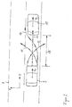
- FIG. 2 In FIG. 2 is shown a possible traffic situation.
- the movements of the vehicles 9, 10 are indicated by a respective velocity arrow v1, v2.
- the vehicle 9, which follows the preceding vehicle 10, is equipped with a device according to the invention for carrying out the method according to the invention. If the speed v1 of the vehicle 9 is much greater than the speed v2 of the vehicle 10, there is a risk of collision in this case, since the distance 15 of the two vehicles is insufficient to allow this collision by a maximum possible deceleration of the vehicle 9 avoid. If in this case an automatically triggered emergency braking would be used, a trajectory would arise for the further vehicle movement, as represented by the single dotted arrow 13.
- the longitudinal force 3 would assume a maximum value ⁇ max * Fn, with the lateral force 4 being equal to zero.
- FIG. 3 a braking force-time diagram is shown, in which the time is plotted on the abscissa 16 and on the ordinate 17, the braking force.
- the time is plotted on the abscissa 16 and on the ordinate 17, the braking force.
- the single-dotted movement trajectory 13 results in a braking force-time diagram, as shown by the single-dotted line 18.
- this would be a horizontal line that would correspond to a maximum possible, constant braking force value.
- an evasive maneuver as represented by the double-dotted movement trajectories 11 and 12, would correspond to the double-dotted curve 19 in the braking force-time diagram of FIG FIG.
- the braking force over the time constant is zero because there is no deceleration of the vehicle.
- the ideally performed by the vehicle, combined braking and steering maneuver according to the triple-dotted movement trajectory 14 is in the braking force-time diagram of FIG. 3 shown as a triple dotted curve. In this case, it is initially very much delayed, whereby the braking force has a high value at low times. In the further course, the curve 20 drops off, since the strength of the deceleration is reduced in order to enter into a steering intervention.
- FIG. 4 another diagram is shown, in which the lateral deflection path y is plotted against the longitudinal path x.
- a hatched area 26 is shown representing the obstacle.
- This area 26 represents the area that the avoidance trajectory must not touch to prevent a collision.
- a likewise simply dotted curve 23 which indicates the spatial movement of the vehicle, is obtained. Since no steering maneuver takes place in this case, this single-dotted line 23 lies on the x-axis. Due to the small distance 15 of the two vehicles 9 and 10, the line 23 from the point 27 touches the hatched area 26, the Represents obstacle. From this point on there is a collision of the vehicle 9 with the object, which is the vehicle 10 in the illustrated case.
- the pure steering maneuver as it is in FIG. 2 represented by the double-dotted movement trajectories 11 and 12, is in the yx diagram of the FIG. 4 as also a double dotted line 24.
- the value y increases continuously, which represents the turning of the vehicle 9.
- the line 24 again touches the shaded area 26, which represents the obstacle. Also in this case, there would be a collision of the two vehicles 9 and 10th
- the combined braking / steering maneuver according to the triple-dotted movement trajectory 14 is in the yx diagram of FIG. 4
- the initially weak steering movement, but the strong deceleration makes the curve 25 initially run very flat, but further increases very strongly towards larger y values, as the braking deceleration is reduced and the steering intervention reinforced becomes. Due to a greatly reduced initial speed, it is possible to perform a stronger steering movement in the later than shown by the line 24. In this case, it is possible to prevent the collision of the two vehicles.
- the method according to the invention calculates all possible movement trajectories between the two illustrated extreme trajectories, namely, on the one hand, a pure. Full braking without steering intervention 13 and on the other hand, a maximum possible steering movement without braking intervention 11 or 12, but all calculated trajectories have in common that the forces acting on the wheels correspond approximately to the forces that lie on the Kamm circle.
Landscapes
- Engineering & Computer Science (AREA)
- Transportation (AREA)
- Mechanical Engineering (AREA)
- Chemical & Material Sciences (AREA)
- Combustion & Propulsion (AREA)
- Automation & Control Theory (AREA)
- Regulating Braking Force (AREA)
- Control Of Driving Devices And Active Controlling Of Vehicle (AREA)
- Steering Control In Accordance With Driving Conditions (AREA)
- Traffic Control Systems (AREA)
Claims (8)
- Procédé de prédiction des trajectoires de déplacement (11, 12, 13, 14) d'un objet (9), en vue d'empêcher une collision ou de diminuer les encombrements de circulation,
caractérisé en ce que
pour la prédiction des trajectoires de déplacement de l'objet, on calcule préalablement uniquement -les trajectoires de l'objet pour lesquelles les forces (3, 4) exercées sur les roues d'un véhicule (9) suite à une combinaison d'actions sur le volant et sur les freins sont de l'ordre de la force maximale (7) qui peut être transmise de la roue à la chaussée. - Procédé selon la revendication 1, caractérisé en ce que l'objet est le véhicule (9) et/ou un autre objet (10) détecté par un ensemble de détecteurs de l'environnement.
- Procédé selon la revendication 2, caractérisé en ce que l'ensemble de détecteurs de l'environnement est constitué d'un détecteur radar, d'un détecteur dit "lidar", d'un détecteur vidéo ou d'une de leurs combinaisons.
- Procédé selon la revendication 1, caractérisé en ce que pour déterminer la force maximale (7) qui peut être à tout instant transmise de la roue à la chaussée, on utilise des signaux supplémentaires provenant d'un dispositif antiblocage et/ou d'une régulation de la dynamique de roulage qui permettent de déterminer la limite de patinage des roues.
- Procédé selon l'une des revendications précédentes, caractérisé en ce qu'une collision du véhicule (9) avec un objet (10) détecté par l'ensemble de détecteurs de l'environnement du véhicule est évitée ou en ce qu'une percussion inévitable est réduite en utilisant les trajectoires prédites de déplacement (14) pour commander automatiquement les dispositifs de ralentissement et/ou pour commander automatiquement les dispositifs de contrôle de direction du véhicule.
- Dispositif de prédiction des trajectoires de déplacement d'un objet,
le dispositif utilisant les signaux d'un ou plusieurs ensembles de détecteurs de l'environnement et des moyens de prédiction étant prévus pour le calcul préalable des trajectoires de déplacement,
caractérisé en ce que
seules sont calculées à l'avance les trajectoires de déplacement du dispositif pour lesquelles les forces exercées sur les roues d'un véhicule sont de l'ordre de la force maximale qui peut être transférée par la roue à la chaussée suite à une combinaison d'actions sur la direction et sur les freins. - Dispositif selon la revendication 6, caractérisé en ce que les trajectoires de déplacement sont calculées pour le véhicule et/ou pour d'autres objets détectés par l'ensemble de détecteurs de l'environnement.
- Dispositif selon les revendications 6 ou 7,
caractérisé en ce que le dispositif présente des moyens de sortie par lesquels les dispositifs de ralentissement du véhicule et/ou les dispositifs de contrôle de la direction du véhicule peuvent être actionnés automatiquement.
Applications Claiming Priority (3)
| Application Number | Priority Date | Filing Date | Title |
|---|---|---|---|
| DE10133029 | 2001-07-11 | ||
| DE10133029 | 2001-07-11 | ||
| PCT/DE2002/002538 WO2003006288A1 (fr) | 2001-07-11 | 2002-07-11 | Procede et dispositif permettant de predire les trajectoires d'un vehicule automobile |
Publications (2)
| Publication Number | Publication Date |
|---|---|
| EP1409310A1 EP1409310A1 (fr) | 2004-04-21 |
| EP1409310B1 true EP1409310B1 (fr) | 2009-04-29 |
Family
ID=7690987
Family Applications (1)
| Application Number | Title | Priority Date | Filing Date |
|---|---|---|---|
| EP02753011A Expired - Lifetime EP1409310B1 (fr) | 2001-07-11 | 2002-07-11 | Procede et dispositif permettant de predire les trajectoires d'un vehicule automobile |
Country Status (5)
| Country | Link |
|---|---|
| US (1) | US7729841B2 (fr) |
| EP (1) | EP1409310B1 (fr) |
| JP (1) | JP4584576B2 (fr) |
| DE (2) | DE50213504D1 (fr) |
| WO (1) | WO2003006288A1 (fr) |
Cited By (3)
| Publication number | Priority date | Publication date | Assignee | Title |
|---|---|---|---|---|
| WO2014114310A1 (fr) | 2013-01-25 | 2014-07-31 | Wabco Gmbh | Procédé permettant de déterminer un critère de déclenchement d'un freinage, et système de freinage d'urgence pour un véhicule |
| US10046761B2 (en) | 2013-01-25 | 2018-08-14 | Wabco Gmbh | Determining an activation criterion for a brake application |
| US11407408B2 (en) * | 2016-09-20 | 2022-08-09 | Zf Cv Systems Europe Bv | Method for performing an evasive maneuver with a utility vehicle combination, and emergency evasion system |
Families Citing this family (73)
| Publication number | Priority date | Publication date | Assignee | Title |
|---|---|---|---|---|
| EP1475765A3 (fr) * | 2003-05-08 | 2006-05-24 | Robert Bosch Gmbh | Appareil pour la detérmination de la possibilité d'un passage d'un véhicule |
| EP1687183B1 (fr) * | 2003-11-14 | 2008-06-25 | Continental Teves AG & Co. oHG | Procede et dispositif pour diminuer les dommages provoques par des accidents |
| DE102004008894A1 (de) * | 2004-02-24 | 2005-09-08 | Robert Bosch Gmbh | Sicherheitssystem für ein Fortbewegungsmittel sowie hierauf bezogenes Verfahren |
| JP4760715B2 (ja) | 2004-12-28 | 2011-08-31 | 株式会社豊田中央研究所 | 車両運動制御装置 |
| DE102005003274A1 (de) | 2005-01-25 | 2006-07-27 | Robert Bosch Gmbh | Verfahren und Vorrichtung zur Vermeidung und/oder Minderung der Folgen von Kollisionen beim Ausweichen vor Hindernissen |
| DE102005023832A1 (de) * | 2005-05-24 | 2006-11-30 | Daimlerchrysler Ag | Verfahren und System zur Vermeidung einer Kollision eines Kraftfahrzeugs mit einem Objekt |
| WO2007031580A1 (fr) | 2005-09-15 | 2007-03-22 | Continental Teves Ag & Co. Ohg | Procede et dispositif permettant de predire une trajectoire de mouvement |
| DE102006034255A1 (de) * | 2005-09-15 | 2007-08-02 | Continental Teves Ag & Co. Ohg | Verfahren und Vorrichtung zum Lenken eines Kraftfahrzeugs |
| DE102005050540A1 (de) * | 2005-10-21 | 2007-05-03 | Man Nutzfahrzeuge Ag | Verfahren und Vorrichtung zur Anpassung von Fahrparametern von Fahrzeugen |
| DE102006033145A1 (de) * | 2006-07-18 | 2008-01-24 | Robert Bosch Gmbh | Verfahren und Vorrichtung zur Vermeidung und/oder Minderung der Folgen von Kollisionen |
| DE102006047131A1 (de) | 2006-10-05 | 2008-04-10 | Robert Bosch Gmbh | Verfahren zum automatischen Steuern eines Fahrzeugs |
| DE102007003978A1 (de) | 2007-01-26 | 2008-07-31 | Bayerische Motoren Werke Aktiengesellschaft | Betriebsverfahren für ein Fahrzeug-Lenksystem mit einem Elektromotor zur Hilfskraftunterstützung |
| DE102007061900B4 (de) | 2007-12-20 | 2022-07-07 | Volkswagen Ag | Spurhalteassistenzsystem und -verfahren für ein Kraftfahrzeug |
| DE102008005305A1 (de) * | 2008-01-21 | 2009-07-23 | Bayerische Motoren Werke Aktiengesellschaft | Verfahren zur Beeinflussung der Bewegung eines Fahrzeugs |
| JP5272448B2 (ja) * | 2008-03-04 | 2013-08-28 | 日産自動車株式会社 | 車両用運転支援装置及び車両用運転支援方法 |
| DE102008034316A1 (de) * | 2008-07-23 | 2010-01-28 | GM Global Technology Operations, Inc., Detroit | Verfahren zum Abbremsen eines Kraftfahrzeugs und Kraftfahrzeug |
| DE112009001524A5 (de) * | 2008-09-10 | 2011-04-07 | Continental Teves Ag & Co. Ohg | Verfahren zur Lenkunterstützung bei Notmanöver |
| US9108600B2 (en) | 2009-05-07 | 2015-08-18 | Continental Teves Ag & Co. Ohg | Method and device for performing closed-loop or open-loop control of the driving stability of a vehicle |
| DE102009049592B4 (de) * | 2009-10-16 | 2018-03-01 | Audi Ag | Verfahren zum Betrieb eines Fahrerassistenzsystems in einem Kraftfahrzeug sowie zugehöriges Kraftfahrzeug |
| US9514647B2 (en) * | 2010-10-20 | 2016-12-06 | GM Global Technology Operations LLC | Optimal acceleration profile for enhanced collision avoidance |
| US9472097B2 (en) | 2010-11-15 | 2016-10-18 | Image Sensing Systems, Inc. | Roadway sensing systems |
| EP2663971A1 (fr) | 2010-11-15 | 2013-11-20 | Image Sensing Systems, Inc. | Système de détection de la circulation hybride et procédé associé |
| EP2681092A1 (fr) | 2011-03-01 | 2014-01-08 | Continental Teves AG & Co. oHG | Dispositif de sécurité pour véhicule automobile et procédé permettant de faire fonctionner un véhicule automobile |
| EP2681085B1 (fr) | 2011-03-01 | 2017-05-10 | Continental Teves AG & Co. oHG | Procédé et dispositif de prédiction et d'adaptation de trajectoires de déplacement de véhicules automobiles |
| US8692690B2 (en) | 2011-03-09 | 2014-04-08 | Xerox Corporation | Automated vehicle speed measurement and enforcement method and system |
| DE102012203673A1 (de) | 2011-03-09 | 2012-10-04 | Continental Teves Ag & Co. Ohg | Sicherheitsvorrichtung für ein Kraftfahrzeug und Verfahren zum Betrieb eines Kraftfahrzeugs |
| DE102011082950B4 (de) * | 2011-09-19 | 2013-08-01 | Ford Global Technologies, Llc | Verfahren zur Durchführung eines automatischen Bremsvorgangs |
| DE102012007127A1 (de) * | 2011-09-24 | 2013-03-28 | Volkswagen Aktiengesellschaft | Verfahren zum Bestimmen einer Bewegungsbahn für ein Fahrzeug |
| WO2013046300A1 (fr) * | 2011-09-26 | 2013-04-04 | トヨタ自動車株式会社 | Système d'aide à la conduite d'un véhicule |
| SE536586C2 (sv) * | 2012-07-02 | 2014-03-11 | Scania Cv Ab | Anordning och förfarande för att bedöma olycksrisk vid framförande av ett fordon |
| JP5527382B2 (ja) * | 2012-10-12 | 2014-06-18 | トヨタ自動車株式会社 | 走行支援システム及び制御装置 |
| DE112012007157B4 (de) * | 2012-11-21 | 2020-10-29 | Toyota Jidosha Kabushiki Kaisha | Fahrunterstützungsvorrichtung und Fahrunterstützungsverfahren |
| EP2934967B1 (fr) | 2012-12-20 | 2019-01-02 | Continental Teves AG & Co. OHG | Procédé et dispositif de freinage et de commande de direction automatisés d'un véhicule |
| CN103072575B (zh) * | 2013-01-18 | 2016-03-30 | 浙江吉利汽车研究院有限公司杭州分公司 | 一种车辆主动防碰撞方法 |
| JP5918167B2 (ja) | 2013-04-09 | 2016-05-18 | アイシン精機株式会社 | 車両挙動制御装置および車両挙動制御システム |
| DE102013215472A1 (de) | 2013-08-06 | 2015-02-12 | Volkswagen Aktiengesellschaft | Planung einer Auslauftrajektorie zur Kollisionsfolgenverminderung |
| EP2990290B1 (fr) | 2014-09-01 | 2019-11-06 | Honda Research Institute Europe GmbH | Procédé et système de planification de manoeuvre post-collision et véhicule équipé d'un tel système |
| DE102014225594A1 (de) * | 2014-12-11 | 2016-06-16 | Bayerische Motoren Werke Aktiengesellschaft | Lenkassistenzverfahren für ein Kraftfahrzeug |
| DE102015001971A1 (de) | 2015-02-19 | 2016-08-25 | Iav Gmbh Ingenieurgesellschaft Auto Und Verkehr | Verfahren und Überwachungsvorrichtung zur Überwachung von Fahrerassistenzsystemen |
| JP6025273B2 (ja) * | 2015-03-17 | 2016-11-16 | 富士重工業株式会社 | 車両の走行制御装置 |
| DE202015002817U1 (de) | 2015-04-17 | 2016-07-19 | GM GLOBAL TECHNOLOGY OPERATION LLC (n. d. Ges. d. Staates Delaware) | Abstandsregelungssystem, Kraftfahrzeug sowie Computerprogrammprodukt |
| DE102015209974A1 (de) * | 2015-05-29 | 2016-12-01 | Bayerische Motoren Werke Aktiengesellschaft | Quer-Längs-kombinierte Trajektorienplanung für ein Fahrzeug |
| DE102015016531A1 (de) | 2015-12-18 | 2017-06-22 | Adam Opel Ag | Fahrerassistenzsystem und Verfahren zur Kollisionsvermeidung |
| DE102015016544A1 (de) * | 2015-12-18 | 2017-06-22 | Adam Opel Ag | Verfahren zum Finden einer Ausweichtrajektorie für ein Fahrzeug |
| DE102015122409A1 (de) * | 2015-12-21 | 2017-06-22 | Valeo Schalter Und Sensoren Gmbh | Verfahren zur Vermeidung einer Kollision eines Kraftfahrzeugs, Fahrerassistenzsystem sowie Kraftfahrzeug |
| US9896096B2 (en) | 2016-04-11 | 2018-02-20 | David E. Newman | Systems and methods for hazard mitigation |
| DE102016207077A1 (de) * | 2016-04-26 | 2017-10-26 | Zf Friedrichshafen Ag | Brems- und Ausweichassistent für Nutzkraftfahrzeuge |
| US9910440B2 (en) * | 2016-05-13 | 2018-03-06 | Delphi Technologies, Inc. | Escape-path-planning system for an automated vehicle |
| DE102016208703A1 (de) * | 2016-05-20 | 2017-11-23 | Ford Global Technologies, Llc | Kraftfahrzeug und Verfahren zum Betreiben eines Kraftfahrzeugs |
| DE102016210921A1 (de) * | 2016-06-20 | 2018-01-04 | Robert Bosch Gmbh | Verfahren zur Durchführung eines fahrerunabhängigen Bremsvorgangs eines Kraftfahrzeugs |
| US10629079B2 (en) * | 2016-12-05 | 2020-04-21 | Ford Global Technologies, Llc | Vehicle collision avoidance |
| CN108327715B (zh) * | 2017-01-18 | 2021-11-09 | 奥迪股份公司 | 驾驶辅助装置、车辆及驾驶辅助方法 |
| DE102017104357A1 (de) | 2017-03-02 | 2018-09-06 | Volkswagen Aktiengesellschaft | Verfahren, vorrichtung und computerlesbares speichermedium mit instruktionen zur bewegungsplanung für ein kraftfahrzeug |
| DE102017208594A1 (de) | 2017-05-22 | 2018-11-22 | Bayerische Motoren Werke Aktiengesellschaft | Prädiktion einer räumlichen Information von Kraftfahrzeugen |
| JP6525402B2 (ja) * | 2017-08-30 | 2019-06-05 | マツダ株式会社 | 車両制御装置 |
| JP6525401B2 (ja) * | 2017-08-30 | 2019-06-05 | マツダ株式会社 | 車両制御装置 |
| JP6910973B2 (ja) * | 2018-02-02 | 2021-07-28 | 日立Astemo株式会社 | 車両制御装置及びその制御方法並びに車両制御システム |
| DE102018128398B3 (de) | 2018-11-13 | 2019-12-19 | Iav Gmbh Ingenieurgesellschaft Auto Und Verkehr | Verfahren zum Vorhersagen des Verhaltens eines Umgebungsobjektes und Fahrerassistenzsystem |
| US10820349B2 (en) | 2018-12-20 | 2020-10-27 | Autonomous Roadway Intelligence, Llc | Wireless message collision avoidance with high throughput |
| US10816635B1 (en) | 2018-12-20 | 2020-10-27 | Autonomous Roadway Intelligence, Llc | Autonomous vehicle localization system |
| DE102019100731A1 (de) | 2019-01-14 | 2020-07-16 | Bayerische Motoren Werke Aktiengesellschaft | Verfahren, System und Computerprogramm zum Abbau kinetischer Energie eines Fahrzeugs |
| US10713950B1 (en) | 2019-06-13 | 2020-07-14 | Autonomous Roadway Intelligence, Llc | Rapid wireless communication for vehicle collision mitigation |
| US10939471B2 (en) | 2019-06-13 | 2021-03-02 | David E. Newman | Managed transmission of wireless DAT messages |
| US10820182B1 (en) | 2019-06-13 | 2020-10-27 | David E. Newman | Wireless protocols for emergency message transmission |
| DE102020118617A1 (de) | 2020-07-15 | 2022-01-20 | Bayerische Motoren Werke Aktiengesellschaft | Verfahren sowie System zur Handhabung einer Situation betreffend ein Fahrzeug und/oder einen Dritten |
| DE102020118615A1 (de) | 2020-07-15 | 2022-01-20 | Bayerische Motoren Werke Aktiengesellschaft | Verfahren sowie System zur Handhabung einer Situation betreffend ein Fahrzeug und/oder einen Dritten |
| DE102020118616A1 (de) | 2020-07-15 | 2022-01-20 | Bayerische Motoren Werke Aktiengesellschaft | Verfahren sowie System zur Handhabung einer Situation betreffend ein Fahrzeug und/oder einen Dritten |
| JP2022025229A (ja) * | 2020-07-29 | 2022-02-10 | カワサキモータース株式会社 | 移動経路生成システム、移動経路生成プログラム及び移動経路生成方法 |
| US11206169B1 (en) | 2020-11-13 | 2021-12-21 | Ultralogic 5G, Llc | Asymmetric modulation for high-reliability 5G communications |
| US20220183068A1 (en) | 2020-12-04 | 2022-06-09 | David E. Newman | Rapid Uplink Access by Parallel Signaling on a 5G Random-Access Channel |
| US20220252404A1 (en) * | 2021-02-10 | 2022-08-11 | Ford Global Technologies, Llc | Self-correcting vehicle localization |
| US20230030815A1 (en) * | 2021-07-29 | 2023-02-02 | Argo AI, LLC | Complementary control system for an autonomous vehicle |
| DE102022128351A1 (de) | 2022-10-26 | 2024-05-02 | Cariad Se | Verfahren zum Durchführen eines zweiteiligen Notbremsvorganges eines fahrenden Fahrzeuges, sowie ein zugehöriges System und Fahrzeug |
Family Cites Families (17)
| Publication number | Priority date | Publication date | Assignee | Title |
|---|---|---|---|---|
| JP3019466B2 (ja) | 1991-04-25 | 2000-03-13 | トヨタ自動車株式会社 | 路面摩擦係数検出装置 |
| JPH0558319A (ja) | 1991-08-27 | 1993-03-09 | Mazda Motor Corp | 車両の接触防止装置 |
| US5519617A (en) * | 1993-05-07 | 1996-05-21 | Ford Motor Company | Torque managed traction control for the drive wheels of an automotive vehicle |
| US5517414A (en) * | 1994-10-03 | 1996-05-14 | Ford Motor Company | Traction control system with active suspension |
| US5471386A (en) * | 1994-10-03 | 1995-11-28 | Ford Motor Company | Vehicle traction controller with torque and slip control |
| US5576959A (en) * | 1995-03-03 | 1996-11-19 | Ford Motor Company | Method for controlling yaw of a wheeled vehicle based on under-steer and over-steer containment routines |
| EP0891903B1 (fr) * | 1997-07-17 | 2009-02-11 | Volkswagen Aktiengesellschaft | Fonction automatique de frein de secours |
| DE19828693A1 (de) * | 1998-06-26 | 1999-12-30 | Volkswagen Ag | Verfahren und Steuereinrichtung zur Minimierung von Unfallfolgen |
| EP1097054B1 (fr) * | 1998-07-17 | 2004-01-07 | Continental Teves AG & Co. oHG | Procede et dispositif servant a determiner un parametre indiquant une valeur de friction maximum momentanee |
| JP3567761B2 (ja) | 1998-10-23 | 2004-09-22 | トヨタ自動車株式会社 | 車両の転舵制御方法および車両用障害物回避装置 |
| JP3853991B2 (ja) | 1998-11-04 | 2006-12-06 | 本田技研工業株式会社 | 車両の走行安全装置 |
| JP2000159077A (ja) | 1998-11-30 | 2000-06-13 | Mazda Motor Corp | 車両の制御装置 |
| US6445308B1 (en) * | 1999-01-12 | 2002-09-03 | Toyota Jidosha Kabushiki Kaisha | Positional data utilizing inter-vehicle communication method and traveling control apparatus |
| JP2000357299A (ja) * | 1999-06-16 | 2000-12-26 | Honda Motor Co Ltd | 車両の走行安全装置 |
| EP1081004B1 (fr) * | 1999-09-06 | 2005-10-12 | Nissan Motor Company, Limited | Méthode et dispositif d'assistance d'actionnement de freinage d'un opérateur de véhicule |
| JP4647055B2 (ja) * | 2000-03-03 | 2011-03-09 | 富士重工業株式会社 | 車両の運動制御装置 |
| US6490518B1 (en) * | 2001-06-29 | 2002-12-03 | General Motors Corporation | Anti-lock brake control method having adaptive exit criteria |
-
2002
- 2002-07-11 EP EP02753011A patent/EP1409310B1/fr not_active Expired - Lifetime
- 2002-07-11 US US10/380,090 patent/US7729841B2/en not_active Expired - Fee Related
- 2002-07-11 JP JP2003512074A patent/JP4584576B2/ja not_active Expired - Fee Related
- 2002-07-11 DE DE50213504T patent/DE50213504D1/de not_active Expired - Lifetime
- 2002-07-11 DE DE10231556A patent/DE10231556A1/de not_active Withdrawn
- 2002-07-11 WO PCT/DE2002/002538 patent/WO2003006288A1/fr active Application Filing
Cited By (6)
| Publication number | Priority date | Publication date | Assignee | Title |
|---|---|---|---|---|
| WO2014114310A1 (fr) | 2013-01-25 | 2014-07-31 | Wabco Gmbh | Procédé permettant de déterminer un critère de déclenchement d'un freinage, et système de freinage d'urgence pour un véhicule |
| DE102013001228A1 (de) | 2013-01-25 | 2014-07-31 | Wabco Gmbh | Verfahren zum Ermitteln eines Auslösekriteriums für eine Bremsung und Notbremssystem für ein Fahrzeug |
| US9555781B2 (en) | 2013-01-25 | 2017-01-31 | Wabco Gmbh | Determining a triggering criterion for vehicle braking |
| US10046761B2 (en) | 2013-01-25 | 2018-08-14 | Wabco Gmbh | Determining an activation criterion for a brake application |
| US10759420B2 (en) | 2013-01-25 | 2020-09-01 | Wabco Gmbh | Method for determining an activation criterion for a brake application and emergency brake system for performing the method |
| US11407408B2 (en) * | 2016-09-20 | 2022-08-09 | Zf Cv Systems Europe Bv | Method for performing an evasive maneuver with a utility vehicle combination, and emergency evasion system |
Also Published As
| Publication number | Publication date |
|---|---|
| JP2004521026A (ja) | 2004-07-15 |
| DE50213504D1 (de) | 2009-06-10 |
| US20040030498A1 (en) | 2004-02-12 |
| WO2003006288A1 (fr) | 2003-01-23 |
| US7729841B2 (en) | 2010-06-01 |
| DE10231556A1 (de) | 2003-01-23 |
| EP1409310A1 (fr) | 2004-04-21 |
| JP4584576B2 (ja) | 2010-11-24 |
Similar Documents
| Publication | Publication Date | Title |
|---|---|---|
| EP1409310B1 (fr) | Procede et dispositif permettant de predire les trajectoires d'un vehicule automobile | |
| EP2948349B1 (fr) | Procédé permettant de déterminer un critère de déclenchement d'un freinage, et système de freinage d'urgence pour un véhicule | |
| EP2948350B1 (fr) | Procédé de détermination d'un critère de déclenchement d'un freinage et système de freinage d'urgence pour mettre en oeuvre le procédé | |
| EP1843924B1 (fr) | Procede et dispositif pour eviter et/ou reduire les consequences de collisions en cas d'evitement d'obstacles | |
| EP2528765B1 (fr) | Métode d'assistance au conducteur pour détecter des objets latéraux | |
| DE102011080789B4 (de) | Verfahren und System zur Regelung der Fahrstabilität | |
| EP1409312B2 (fr) | Procede et dispositif de commande automatique du systeme de deceleration d'un vehicule | |
| EP1387183B1 (fr) | Procédé et dispositif pour la détermination d'une collision inevitable | |
| EP2323890B1 (fr) | Procede d'assistance a la direction en cas de manoeuvre d'urgence | |
| EP1530527B1 (fr) | Procede et dispositif pour declencher automatiquement un processus de freinage d'urgence dans un vehicule | |
| EP2252491B1 (fr) | Assistant de guidage longitudinal comportant une fonction d'assistance latérale pour des véhicules motorisés | |
| EP3515781A1 (fr) | Procédé permettant d'effectuer une manoeuvre d'évitement avec un attelage de véhicule utilitaire, ainsi que système d'évitement d'urgence | |
| WO2006053655A1 (fr) | Procede pour eviter une collision ou pour reduire les consequences d'une collision et dispositif pour realiser ce procede | |
| WO2009092416A1 (fr) | Système d’aide à la conduite et procédé pour aider le conducteur d’un véhicule automobile à respecter une trajectoire délimitée par des marquages de voie | |
| DE102007027644A1 (de) | Fahrzeug-Brems-Regelsystem | |
| DE10102771A1 (de) | Einrichtung zum Bereitstellen von Signalen in einem Kraftfahrzeug | |
| EP1694542B1 (fr) | Systeme de reglage de la dynamique de conduite pour un vehicule automobile comprenant une montee en pression anticipee pour la roue a regler | |
| DE10102772A1 (de) | Vorrichtung zur adaptiven Fahrgeschwindigkeitsregelung eines Kraftfahrzeugs | |
| DE102007027494A1 (de) | Verfahren und eine Vorrichtung zur Unterstützung des Fahrers eines Fahrzeugs bei der Fahrzeugführung | |
| EP3010786A1 (fr) | Assistant d'évitement et de freinage pour véhicules automobiles | |
| DE102008013988B4 (de) | Verfahren und Vorrichtung zum Durchführen eines Ausweichmanövers | |
| DE102006057842A1 (de) | Verfahren zur Unterstützung des Fahrers eines Fahrzeugs bei der Querführung des Fahrzeugs und Fahrerassistenzsystem zur Durchführung des Verfahrens | |
| DE102014220300A1 (de) | Rangierassistent und Rangierassistenzverfahren für ein Kraftfahrzeug | |
| DE10349211A1 (de) | Bremsassistent für Kraftfahrzeuge | |
| WO2012084502A1 (fr) | Procédé pour garer ou manœuvrer un véhicule automobile à basse vitesse et dispositif pour la mise en œuvre de ce procédé |
Legal Events
| Date | Code | Title | Description |
|---|---|---|---|
| PUAI | Public reference made under article 153(3) epc to a published international application that has entered the european phase |
Free format text: ORIGINAL CODE: 0009012 |
|
| 17P | Request for examination filed |
Effective date: 20040211 |
|
| AK | Designated contracting states |
Kind code of ref document: A1 Designated state(s): AT BE BG CH CY CZ DE DK EE ES FI FR GB GR IE IT LI LU MC NL PT SE SK TR |
|
| RIN1 | Information on inventor provided before grant (corrected) |
Inventor name: HERMSEN, WOLFGANG Inventor name: KNOOP, MICHAEL Inventor name: HEINEBRODT, MARTIN Inventor name: WEILKES, MICHAEL Inventor name: WILHELM, ULF Inventor name: WINNER, HERMANN Inventor name: UHLER, WERNER Inventor name: OECHSLE, FRED Inventor name: BRAEUCHLE, GOETZ Inventor name: THIELE, JOACHIM Inventor name: STAEMPFLE, MARTIN |
|
| GRAP | Despatch of communication of intention to grant a patent |
Free format text: ORIGINAL CODE: EPIDOSNIGR1 |
|
| GRAS | Grant fee paid |
Free format text: ORIGINAL CODE: EPIDOSNIGR3 |
|
| GRAA | (expected) grant |
Free format text: ORIGINAL CODE: 0009210 |
|
| AK | Designated contracting states |
Kind code of ref document: B1 Designated state(s): DE GB IT |
|
| REG | Reference to a national code |
Ref country code: GB Ref legal event code: FG4D Free format text: NOT ENGLISH |
|
| REF | Corresponds to: |
Ref document number: 50213504 Country of ref document: DE Date of ref document: 20090610 Kind code of ref document: P |
|
| PLBI | Opposition filed |
Free format text: ORIGINAL CODE: 0009260 |
|
| PLAX | Notice of opposition and request to file observation + time limit sent |
Free format text: ORIGINAL CODE: EPIDOSNOBS2 |
|
| 26 | Opposition filed |
Opponent name: CONTI TEMIC MICROELECTRONIC GMBH ABT. PATENTE & LI Effective date: 20100129 |
|
| PLAF | Information modified related to communication of a notice of opposition and request to file observations + time limit |
Free format text: ORIGINAL CODE: EPIDOSCOBS2 |
|
| PLBB | Reply of patent proprietor to notice(s) of opposition received |
Free format text: ORIGINAL CODE: EPIDOSNOBS3 |
|
| PG25 | Lapsed in a contracting state [announced via postgrant information from national office to epo] |
Ref country code: IT Free format text: LAPSE BECAUSE OF FAILURE TO SUBMIT A TRANSLATION OF THE DESCRIPTION OR TO PAY THE FEE WITHIN THE PRESCRIBED TIME-LIMIT Effective date: 20090429 |
|
| PLCK | Communication despatched that opposition was rejected |
Free format text: ORIGINAL CODE: EPIDOSNREJ1 |
|
| PLBN | Opposition rejected |
Free format text: ORIGINAL CODE: 0009273 |
|
| STAA | Information on the status of an ep patent application or granted ep patent |
Free format text: STATUS: OPPOSITION REJECTED |
|
| 27O | Opposition rejected |
Effective date: 20130524 |
|
| REG | Reference to a national code |
Ref country code: DE Ref legal event code: R100 Ref document number: 50213504 Country of ref document: DE Effective date: 20130524 |
|
| PGFP | Annual fee paid to national office [announced via postgrant information from national office to epo] |
Ref country code: GB Payment date: 20200724 Year of fee payment: 19 Ref country code: DE Payment date: 20200924 Year of fee payment: 19 |
|
| REG | Reference to a national code |
Ref country code: DE Ref legal event code: R119 Ref document number: 50213504 Country of ref document: DE |
|
| GBPC | Gb: european patent ceased through non-payment of renewal fee |
Effective date: 20210711 |
|
| PG25 | Lapsed in a contracting state [announced via postgrant information from national office to epo] |
Ref country code: GB Free format text: LAPSE BECAUSE OF NON-PAYMENT OF DUE FEES Effective date: 20210711 Ref country code: DE Free format text: LAPSE BECAUSE OF NON-PAYMENT OF DUE FEES Effective date: 20220201 |