EP1406134B1 - Sicherheitsnetzwerksystem, sicherheits-slave und sicherheitssteuerung - Google Patents
Sicherheitsnetzwerksystem, sicherheits-slave und sicherheitssteuerung Download PDFInfo
- Publication number
- EP1406134B1 EP1406134B1 EP02738778A EP02738778A EP1406134B1 EP 1406134 B1 EP1406134 B1 EP 1406134B1 EP 02738778 A EP02738778 A EP 02738778A EP 02738778 A EP02738778 A EP 02738778A EP 1406134 B1 EP1406134 B1 EP 1406134B1
- Authority
- EP
- European Patent Office
- Prior art keywords
- safety
- slave
- information
- network
- mpu
- Prior art date
- Legal status (The legal status is an assumption and is not a legal conclusion. Google has not performed a legal analysis and makes no representation as to the accuracy of the status listed.)
- Expired - Lifetime
Links
Images


Classifications
-
- G—PHYSICS
- G05—CONTROLLING; REGULATING
- G05B—CONTROL OR REGULATING SYSTEMS IN GENERAL; FUNCTIONAL ELEMENTS OF SUCH SYSTEMS; MONITORING OR TESTING ARRANGEMENTS FOR SUCH SYSTEMS OR ELEMENTS
- G05B19/00—Programme-control systems
- G05B19/02—Programme-control systems electric
- G05B19/04—Programme control other than numerical control, i.e. in sequence controllers or logic controllers
- G05B19/05—Programmable logic controllers, e.g. simulating logic interconnections of signals according to ladder diagrams or function charts
- G05B19/058—Safety, monitoring
-
- G—PHYSICS
- G05—CONTROLLING; REGULATING
- G05B—CONTROL OR REGULATING SYSTEMS IN GENERAL; FUNCTIONAL ELEMENTS OF SUCH SYSTEMS; MONITORING OR TESTING ARRANGEMENTS FOR SUCH SYSTEMS OR ELEMENTS
- G05B19/00—Programme-control systems
- G05B19/02—Programme-control systems electric
- G05B19/04—Programme control other than numerical control, i.e. in sequence controllers or logic controllers
- G05B19/042—Programme control other than numerical control, i.e. in sequence controllers or logic controllers using digital processors
- G05B19/0428—Safety, monitoring
-
- G—PHYSICS
- G05—CONTROLLING; REGULATING
- G05B—CONTROL OR REGULATING SYSTEMS IN GENERAL; FUNCTIONAL ELEMENTS OF SUCH SYSTEMS; MONITORING OR TESTING ARRANGEMENTS FOR SUCH SYSTEMS OR ELEMENTS
- G05B9/00—Safety arrangements
- G05B9/02—Safety arrangements electric
-
- H—ELECTRICITY
- H04—ELECTRIC COMMUNICATION TECHNIQUE
- H04B—TRANSMISSION
- H04B3/00—Line transmission systems
- H04B3/54—Systems for transmission via power distribution lines
- H04B3/542—Systems for transmission via power distribution lines the information being in digital form
-
- H—ELECTRICITY
- H04—ELECTRIC COMMUNICATION TECHNIQUE
- H04L—TRANSMISSION OF DIGITAL INFORMATION, e.g. TELEGRAPHIC COMMUNICATION
- H04L12/00—Data switching networks
- H04L12/28—Data switching networks characterised by path configuration, e.g. LAN [Local Area Networks] or WAN [Wide Area Networks]
- H04L12/40—Bus networks
- H04L12/403—Bus networks with centralised control, e.g. polling
-
- G—PHYSICS
- G05—CONTROLLING; REGULATING
- G05B—CONTROL OR REGULATING SYSTEMS IN GENERAL; FUNCTIONAL ELEMENTS OF SUCH SYSTEMS; MONITORING OR TESTING ARRANGEMENTS FOR SUCH SYSTEMS OR ELEMENTS
- G05B2219/00—Program-control systems
- G05B2219/10—Plc systems
- G05B2219/14—Plc safety
- G05B2219/14114—Integrity, error detector, switch off controller, fail safe
-
- G—PHYSICS
- G05—CONTROLLING; REGULATING
- G05B—CONTROL OR REGULATING SYSTEMS IN GENERAL; FUNCTIONAL ELEMENTS OF SUCH SYSTEMS; MONITORING OR TESTING ARRANGEMENTS FOR SUCH SYSTEMS OR ELEMENTS
- G05B2219/00—Program-control systems
- G05B2219/10—Plc systems
- G05B2219/15—Plc structure of the system
- G05B2219/15005—Set switches defining control function
-
- G—PHYSICS
- G05—CONTROLLING; REGULATING
- G05B—CONTROL OR REGULATING SYSTEMS IN GENERAL; FUNCTIONAL ELEMENTS OF SUCH SYSTEMS; MONITORING OR TESTING ARRANGEMENTS FOR SUCH SYSTEMS OR ELEMENTS
- G05B2219/00—Program-control systems
- G05B2219/30—Nc systems
- G05B2219/31—From computer integrated manufacturing till monitoring
- G05B2219/31131—Field device with gateway functions for communication with pc and other field devices
-
- G—PHYSICS
- G05—CONTROLLING; REGULATING
- G05B—CONTROL OR REGULATING SYSTEMS IN GENERAL; FUNCTIONAL ELEMENTS OF SUCH SYSTEMS; MONITORING OR TESTING ARRANGEMENTS FOR SUCH SYSTEMS OR ELEMENTS
- G05B2219/00—Program-control systems
- G05B2219/30—Nc systems
- G05B2219/31—From computer integrated manufacturing till monitoring
- G05B2219/31189—Time multiplex
-
- G—PHYSICS
- G05—CONTROLLING; REGULATING
- G05B—CONTROL OR REGULATING SYSTEMS IN GENERAL; FUNCTIONAL ELEMENTS OF SUCH SYSTEMS; MONITORING OR TESTING ARRANGEMENTS FOR SUCH SYSTEMS OR ELEMENTS
- G05B2219/00—Program-control systems
- G05B2219/30—Nc systems
- G05B2219/31—From computer integrated manufacturing till monitoring
- G05B2219/31211—Communicate diagnostic data from intelligent field device controller to central
-
- G—PHYSICS
- G05—CONTROLLING; REGULATING
- G05B—CONTROL OR REGULATING SYSTEMS IN GENERAL; FUNCTIONAL ELEMENTS OF SUCH SYSTEMS; MONITORING OR TESTING ARRANGEMENTS FOR SUCH SYSTEMS OR ELEMENTS
- G05B2219/00—Program-control systems
- G05B2219/30—Nc systems
- G05B2219/36—Nc in input of data, input key till input tape
- G05B2219/36159—Detachable or portable programming unit, display, pc, pda
-
- H—ELECTRICITY
- H04—ELECTRIC COMMUNICATION TECHNIQUE
- H04B—TRANSMISSION
- H04B2203/00—Indexing scheme relating to line transmission systems
- H04B2203/54—Aspects of powerline communications not already covered by H04B3/54 and its subgroups
- H04B2203/5429—Applications for powerline communications
- H04B2203/5458—Monitor sensor; Alarm systems
-
- H—ELECTRICITY
- H04—ELECTRIC COMMUNICATION TECHNIQUE
- H04L—TRANSMISSION OF DIGITAL INFORMATION, e.g. TELEGRAPHIC COMMUNICATION
- H04L12/00—Data switching networks
- H04L12/28—Data switching networks characterised by path configuration, e.g. LAN [Local Area Networks] or WAN [Wide Area Networks]
- H04L12/46—Interconnection of networks
- H04L12/4604—LAN interconnection over a backbone network, e.g. Internet, Frame Relay
- H04L12/462—LAN interconnection over a bridge based backbone
- H04L12/4625—Single bridge functionality, e.g. connection of two networks over a single bridge
-
- H—ELECTRICITY
- H04—ELECTRIC COMMUNICATION TECHNIQUE
- H04L—TRANSMISSION OF DIGITAL INFORMATION, e.g. TELEGRAPHIC COMMUNICATION
- H04L12/00—Data switching networks
- H04L12/28—Data switching networks characterised by path configuration, e.g. LAN [Local Area Networks] or WAN [Wide Area Networks]
- H04L12/40—Bus networks
- H04L2012/4026—Bus for use in automation systems
-
- Y—GENERAL TAGGING OF NEW TECHNOLOGICAL DEVELOPMENTS; GENERAL TAGGING OF CROSS-SECTIONAL TECHNOLOGIES SPANNING OVER SEVERAL SECTIONS OF THE IPC; TECHNICAL SUBJECTS COVERED BY FORMER USPC CROSS-REFERENCE ART COLLECTIONS [XRACs] AND DIGESTS
- Y02—TECHNOLOGIES OR APPLICATIONS FOR MITIGATION OR ADAPTATION AGAINST CLIMATE CHANGE
- Y02P—CLIMATE CHANGE MITIGATION TECHNOLOGIES IN THE PRODUCTION OR PROCESSING OF GOODS
- Y02P90/00—Enabling technologies with a potential contribution to greenhouse gas [GHG] emissions mitigation
- Y02P90/02—Total factory control, e.g. smart factories, flexible manufacturing systems [FMS] or integrated manufacturing systems [IMS]
Definitions
- the present invention relates to a safety network system, a safety slave, and a safety controller.
- a programmable controller (hereinafter, referred to as "PLC") used in factory automation (hereinafter, referred to as “FA”) executes control in such a manner that it is supplied with ON/OFF information from input devices such as switches, sensors, and the like, executes a logical operation using a sequence program (also referred to as user's program) written in a ladder language and the like, and outputs the signals of ON/OFF information to output devices such as relays, valves, actuators, and the like according to a result of the arithmetic operation.
- PLC programmable controller
- FA factory automation
- the input and output devices may be directly connected to the PLC or may be connected to the PLC through a network.
- a network system in which the input and output devices are connected to the PLC through the network, is constructed, the ON/OFF information is transmitted and received through the network.
- the information is ordinarily transmitted using a master/slave system in which the PLC acts as a master and the input and output devices act as slaves.
- a failsafe (safety) system is being introduced also in the control executed by the PLC. That is, a safety function is built in not only the PLC and the respective devices but also in the network.
- the safety function is a function for executing an output after a safe state is confirmed.
- failsafe function is executed when the network system is placed in a dangerous state by that an emergency stop switch is depressed, sensors such as a light curtain and the like detect an incoming person (a part of a body), and the like so that the safety system is set to a safe side and the operation thereof is stopped.
- the safety system is a system that issues an output only when the safe state is confirmed by the safety function and operates a machine. Therefore, when the safe state cannot be confirmed, the machine is stopped.
- the slave When a slave receives a request from, for example, the PLC (master), the slave can return its state as a response, thereby the PLC can obtain the state of the slave connected to the network.
- the PLC master
- the safety information (danger information) can be transmitted when the safety devices and the safety slaves operate normally, there is a case that the safety information cannot be transmitted to the safety PLC because an apparatus itself fails or the network is in an abnormal state. In this case, the failsafe function must be also executed determining that the abnormal state occurs.
- a safety slave safety device
- a simultaneous transmissive communication timeout
- a receiving time from which the timeout occurs must be set at least longer than a communication cycle time in a normal state, and thus when the communication cycle time increases as described above, a period of time necessary to determine whether or not the network is abnormal also increases , which prevents the prompt execution of a processing when the abnormal state occurs.
- An obj ect of the present invention is to provide a safety network system, a safety slave, and a safety controller that can promptly transmit whether or not safety devices (safety device) are safe to a master (safety controller) and other devices, promptly execute the failsafe function when an abnormal (dangerous) state occurs, and further confirm the detailed information of an overall system and promptly specify a malfunction when a dangerous portion is specified or the system is debagged.
- safety devices safety device
- master safety controller
- a safety slave according to the preamble of claim 1 is known from DE 195 16 933 C1 .
- a safety slave according to the present invention is as defined in claim 1.
- the safety input informations are informations indicating a state of safety devices, that is, informations for determining whether or not the safety devices are "safe” or “not safe (abnormal, danger)", and may be also called safety informations. Further, information as to whether or not the safety slave itself is in a safe state may be also included in the safety informations. It is needless to say that information other than the above informations may be included in the safety input informations. In particular, as described later, when the safety input informations are sent as they are, it is preferable to add additional information other than the safety input informations because the devices such as the safety controller and the like that receive the safety input informations can understand a state in detail.
- the safety determination means is realized by an MPU 23 in an embodiment. Further, in the embodiment, safety is determined such that when all the safety input informations indicate “safe”, the result of determination of safety is made “safe”, whereas when there exists even one safety input information that indicates not safe, the result of determination of safety is made "not safe (abnormal, dangerous)". However, other conditions may be set to determine safety.
- a result of determination of safety (safe or not safe, and the like), which is determined based on the plurality of safety input informations, is sent to the safety controller in place of sending all the safety input informations they are, which can reduce an amount of data returned to the safety controller. Accordingly, a period of time necessary to one communication cycle can be reduced, and thus when an abnormal state (dangerous state) occurs, it can be promptly notified to the safety controller.
- the safety determination means can easily make determination by executing, for example, a logic operation (AND).
- the result of determination of safety may be regarded as a result of the logic operation of a plurality of safety input informations or as a result of compression processing of predetermined data.
- the devices such as the safety controller and the like, which have received the result of determination of safety, can determine whether or not a system is safe while reducing an amount of data.
- a safety slave comprises a function for notifying the plurality of safety input informations as they are as the information composed of aggregated data.
- the function corresponds to the transmission of information in a "detailed information mode". It is needless to say that although this function may not be provided, the provision of the function makes it possible to recognize the individual states of the respective safety devices and the like on the safety controller side, which will be useful to specify dangerous portions and to variously analyze the contents of malfunctions.
- the safety input informations are composed of the aggregated data, it is possible to notify not only all the safety input informations as they are but also to use the aggregated data obtained by compressing a part of the informations as the information to be notified. That is, when it is assumed that eight safety input informations are received, safety is determined as to a part of the informations (four informations) similarly to the above case, wherein it is determined that the system is safe when all the four informations are safe, and it is determined that the system is not safe when any one of the informations is not safe. Then, the data obtained by aggregating a result of the above determination and the remaining four safety input informations can be arranged as the aggregated data.
- the safety input informations are partly sent as they are as described above, the number of the informations need not be half the total number of the informations as in the example, and any arbitrary number of the informations may be used.
- the safety slave may comprise a function for detecting the cause of danger of at least one of the safety slave itself and the devices managed thereby as well as transmitting the cause of danger by adding it to the information.
- the addition of the cause of danger enables the execution of a more detailed analysis and the like.
- the above information, which is sent together with the cause of danger may be the result of determination of safety described above or may be the aggregated data composed of the plurality of safety input informations. Informations other than the above may be of course sent together with the cause of the danger.
- the safety slave of the present invention is not limited to an ordinary slave to which the safety devices are connected and may be a safety gateway to which a different type of a field bus is connected.
- the safety input informations are safety input informations from a plurality of other safety slaves connected to the safety gateway. Accordingly, the result of determination of safety is obtained by determining whether or not the safety condition is satisfied based on the respective safety input informations obtained from the plurality of other safety slaves.
- the plurality of safety input informations having been obtained can be notified as they are as the aggregated data.
- the plurality of safety input informations having been obtained can be transmitted by time-sharing in each predetermined unit.
- a unit of node can be used as the predetermined unit as shown in, for example, the embodiment ( Fig. 9(c) ).
- useful information can be received effectively and promptly by receiving the informations of necessary units in the detailed information mode and receiving the result of determination of safety from the units other than the necessary units.
- the transmission modes may be selectively switched based on a communication command from the safety controller.
- the safety slave may comprise a setting switchmeans for switching the transmission modes, and the transmission modes may be switched in response to an indication from the selection switch means.
- a safety network system is constructed by connecting a safety controller to the safety slave composed of the various types of the arrangements described above through a safety network. Then, the information output from the safety slave is transmitted to the safety controller through the safety network.
- a safety controller is a safety controller which is connected to the safety network and can construct a safety network system together with the safety slaves.
- the safety controller comprises a state memory unit for storing and holding whether or not the state of the safety network system is in a safe state, wherein when a present state stored in the state memory unit is safe, the safety controller requests the safety slave to transmit the result of determination of safety, and when the present state stored in the state memory unit is not safe, the safety controller requests the safety slave to transmit detailed information which is in more detail than the result of determination of safety:
- the state storing unit corresponds to a state storing unit that stores a safety flag. Note that the safety controller for constructing the safety network system according to the present invention need not be provided with the state storing unit and the function for issuing a request based on the present state stored in the state storing unit as described above.
- another safety slave is a safety slave which can be connected to a safety network and transmits the information based on the plurality of safety input informations managed by the safety slave to other nodes connected to the safety network.
- the safety slave comprises a safety determination means for determining whether or not a safety condition is satisfied based on the plurality of safety input informations and a means for transmitting a result of determination of safety determined by the safety determination means as the information.
- Timing at which the safety slave transmits the safety information may be determined based on any of an internal trigger and an external trigger. Further, also in the safety slave that makes transmission to the other node, the safety slave is preferably provided with a function for notifying the plurality of safety input informations as they are as the above information composed of aggregated data. This function corresponds to the transmission in the "detailed information mode" in the embodiment. It is needless to say that although this function may not be provided, the provision of the function makes it possible to recognize the individual states of the respective safety devices and the like on the safety controller side, which is useful to specify dangerous portions and to variously analyze the contents of malfunctions.
- the safety slave may comprise a function for detecting the cause of danger of at least one of the safety slave itself and the devices managed thereby as well as transmitting the cause of danger by adding it to the information.
- a more detailed analysis and the like can be executed by the adding the cause of danger.
- the information sent together with the cause of danger may be the result of determination of safety described above or the aggregated data composed of the plurality of safety input informations. Informations other than the above information may be of course sent together with the cause of the danger.
- the safety slave of the present invention is not limited to an ordinary slave to which the safety devices are connected and may be a safety gateway to which a different type of a field bus is connected.
- the safety input informations are the safety input informations from a plurality of other safety slaves connected to the safety gateway. Accordingly, the result of determination of safety is determined by determining whether or not the safety condition is satisfied based on the respective safety input informations obtained from the plurality of other safety slaves.
- a plurality of obtained safety input informations can be notified as they are as aggregated data.
- another mode of the detailed information is to enable the plurality of obtained safety input informations to be transmitted in each predetermined unit by time-sharing.
- the transmission modes may be selectively switched based on a communication command from the other node.
- the safety slave may comprise a setting switch means for switching the transmission modes, and the transmission modes may be switched in response to an indication from the selection switch means.
- the safety network using the above safety slave may be arranged such that the information output from the safety slave is transmitted to the other node through the safety network.
- Fig. 1 shows an example of a safety network system to which the present invention is applied.
- a safety PLC 1 master
- a safety network field bus
- Informations are transmitted and received between the safety PLC 1 and the safety slaves 2 using a master/slave system.
- safety devices 4 such as various types of input devices, output devices, and the like, in addition to safety door switches, safety limit switches, emergency stop switches, and the like.
- the safety PLC 1 is arranged by coupling a plurality of units, for example, a CPU unit, a master unit (communication unit), an I/O unit, and the like. In this case, a master unit is connected to the safety network 3.
- a safety function (failsafe function) is built in all of the various types of the devices constituting the safety network system.
- the safety function is a function for executing an output (control) after a safe state is confirmed thereby. Then, when a dangerous state occurs, the failsafe function is executed, thereby the operation of the system is stopped after it is switched to a safe side. That is, in the safety system, the failsafe function is executed when the network system is placed in the dangerous state by that an emergency stop switch is depressed, sensors such as a light curtain and the like detect an incoming person (a part of a body), and the like so that the system is switched to the safe side and the operation thereof is stopped.
- the safety system is a system for executing an output only when it is confirmed that the system is in the safe state by the safety function and operating machines. Therefore, when the safe state cannot be confirmed, the machines are stopped.
- Each of the safety slaves 2 includes a plurality of terminal tables 2a, and the various types of the safety devices 4 are connected to the terminal tables 2a.
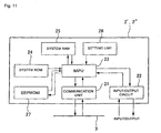
- the internal structure of the safety slave 2 is arranged as shown in Fig. 2 .
- the safety slave 2 includes a communication unit 21, which is connected to the safety network 3 and transmits and receives data to and from the safety PLC 1 (master), an input/output circuit 22 for transmitting and receiving data to and from the safety devices 4 connected to the safety slave 2, and an MPU 23 for reading out a program stored in a system ROM 24 and executing predetermined processings.
- the MPU 23 executes processing for returning informations (safety information and the like), which are obtained from the safety devices 4 through the input/output circuit 22, to the safety PLC 1 (master) through the communication unit 21 and the safety network 3 in response to a request addressed thereto and received thereby through the communication unit 21.
- the MPU 23 creates a safety response (transmission frame including safety information) based on a request from the safety PLC1 (master) and returns it to the safety PLC1 (master).
- a safety response having a small amount of data in a result notification mode
- a safety response having a large amount of data in a detailed information mode.
- the safety slave 2 collects the safety input informations from all the safety devices 4 connected thereto, determines whether or not all the safety devices 4 are safe, and stores a result of determination in a data unit.
- this embodiment includes the two types of the modes having a different content, and a safety response having a different content is created from each of the modes. Then, when a safety request is issued, a safety response is not created in each of the modes (although it may be created in each of them) but is created in any one of the modes and transmitted.
- a specific transmission frame used in the result notification mode is as shown in, for example, in Fig. 3(a) .
- all the plurality of channels managed by the safety slave 2 are handled as one unit, and when all the channels are safe, the channels are determined safe.
- the present invention is not limited thereto , and the plurality of channels may be separated into units and it may be determined whether or not the channels are safe in each of the separated units. That is, when there is an input of, for example, 8 channels, the 8 channels are managed by being separated into first to fourth channels and into fifth to eighth channels, and a case that any of the first to fourth channels is dangerous and a case that any of the fifth to eighth channels is dangerous are separately transmitted.
- the range of equipment that is stopped by applying the failsafe function can be reduced.
- the equipment is divided into apparatuses A to C, and a switch, a sensor, and the like relating to the dangerous state of the apparatus A are connected to the first to fourth channels of the safety slave.
- the two emergency stop switches of the apparatus B are connected to the fifth and sixth channels of the safety slave, and the emergency stop switch of the apparatus C is connected to the seventh channel thereof (an eight channel is not used). At this time, if the switch of the seventh channel is turned ON, only the apparatus C is stopped and the other apparatuses A and B can be operated as they are.
- productivity is not deteriorated as compared with a case that all the apparatuses (entire equipment) are stopped by the dangerous input of the seventh channel. Even if the channels are divided into the plurality of units, it is more effective than the case that the safety informations of all the safety devices 4 are transmitted.
- the safety input informations of the plurality of channels obtained from the safety devices 4 connected to the safety slave 2 are notified as they are as aggregated data similarly to a known technology.
- a specific transmission frame used in the specific information mode is as shown in, for example, in Fig. 3(b) .
- safety informations for the eight channels are stored in the data of the transmission frame.
- the request from the safety PLC 1, which determines transmission is to be executed in any of the modes is arranged as a transmission frame shown in, for example, Fig. 3(c) . That is, the transmission frame includes an address to which the request is issued (address of safety frame, all the safety slaves can be designated by simultaneous transmissive communication), a mode indication flag (01: result mode, 11: detailed mode), and the like.
- the safety PLC 1 stops the system.
- the failsafe function it is important whether or not there exists a safety device which detects the data dangerous state, and it is not very important to specify the safety device that detects the dangerous state and to find a cause of the detected dangerous state.
- a result notification request command is ordinarily issued from the safety PLC 1 as shown in Fig. 4(a) , and the respective safety slaves 2, which have received the command, return a result of determination of safety (2 bits) obtained thereby based on their determination to the safety PLC 1 as a safety response.
- a cycle time of communication executed once can be reduced, and safety information, in particular, safety information indicating a dangerous state can be notified promptly.
- the data unit of the transmission frame requires an amount of information of 2 bytes in an ordinary method because safety information of eight channels is transmitted in an ordinary method.
- the data unit of the transmission frame requires only two bits used for the result of determination of safety regardless of the number of channels.
- the processing function of the MPU on the safety PLC 1 side is arranged as shown in the flowchart of Fig. 5 to realize the processings described above.
- a safety flag showing a present state.
- the MPU operates as described below on the basis of the above premise. That is, first, the MPU determines whether or not the safety flag is set to "1" (ST1). When the flag is set to "1", since the system is in the safe state and operates normally, the MPU transmits the result notification request command to prepare the occurrence of an abnormal state (dangerous state) (ST2).
- the MPU waits to receive a safety response from the safety slaves 2 (ST4), and when the MPU normally receives the response, it determines whether or not the contents of the received safety information are safe (ST5). When the contents are safe, the MPU sets the safety flag to 1 (ST6). Whereas, when the MPU cannot normally receive the safety response (No at step ST4), and when the contents of the received safety information show the dangerous state, the MPU sets the safety flag to "0" (ST7).
- a case that the MPU cannot normally receive the safety response and the determination at step S4 is branched to No includes (1) a communication error such as noise and the like, (2) a communication error on a transmission side or a reception side (which can be recovered), (3) removal or interruption of a communication line, (4) a malfunction of the transmitting function of a slave, (5) a malfunction of the receiving function of the master (safety PLC), and the like.
- the safety response can be normally received in a subsequent communication cycle and a communication can be continued.
- the safety PLC cannot receive the safety response in any one of the modes.
- the MPU 23 waits for a receiving frame as shown in the flowchart of Fig. 6 (ST11). Then, the MPU 23 confirms the address to which the received frame is transmitted and determines whether or not the address is the address of a self-node (ST12). When the address is the address of other node, the MPU 23 returns to step 1 and waits for a next receiving frame.
- the MPU 23 determines whether or not the result notification command is requested (ST13), and when the result notification command is requested, the MPU 23 sets a result of determination of safety, that is, a result of an arithmetic operation which determines whether or not all the safety devices connected thereto are safe to a transmission buffer and returns it the safety response (ST14 and ST15)
- the MPU 23 determines whether or not the request command is the detailed information command (ST16).
- the MPU 23 sets the safety I/O inputs from all the safety devices connected thereto to the transmission buffer before the arithmetic operation is executed and returns it as the safety response (ST17, ST15).
- the MPU 23 does not transmit the safety response based on the reception of this time, returns to step 11, and waits for a next frame. Thereafter, the MPU 23 repeats the above processings and returns various types of safety responses according to the request.
- Fig. 7 shows the main portion of a second embodiment of the present invention. That is, although this embodiment is arranged based on the first embodiment, the information notified in the detailed information mode is different from that of the first embodiment. That is, when information in the detailed information mode is requested from the safety PLC, a safety response having a frame arrangement as shown in Fig. 7(b) is returned. Specifically, it is determined whether or not the safety slave itself satisfies the safety condition based on the safety input informations from the plurality of channels in the range of the safety input informations similarly to the transmission frame in the result notification mode ( Fig. 7(a) ), and a cause of danger is notified in addition to a code indicating safety/danger (safety determination result code) determined by the above determination.
- safety/danger safety determination result code
- the cause of danger includes such cases that "a result of self-diagnosis of the safety slave itself is NG”, “a result of diagnosis of a safety device connected to the safety slave is NG", “the outputs from the safety devices (emergency stop push button and the like) is in a state of intending to cause a dangerous state", and the like.
- the cause relates to the safety device connected to the safety slave, channel information for specifying the safety device is included.
- the embodiment is not limited thereto and may transmit the cause-of-danger in addition to, for example, the safety information transmitted in the detailed information in the fist embodiment.
- the detailed information mode in the first embodiment may be arranged as a detailed information mode 1
- the detailed information mode in the second embodiment may be arranged as a detailed information mode 2
- a flag may be provided to discriminate three types of the modes, that is, these two detailed information modes and the result notification mode used in an ordinary time, and responding to the request from the safety PLC, a safety response may be returned in a mode alternatively selected from these three types of the modes.
- Fig. 8 shows a third embodiment of the present invention.
- This embodiment shows an example that is applied to a multi-stage network system different from the above embodiments.
- the multi-stage network system has a different type of a field bus connected to the system, and the different type of the field bus is arranged such that a safety gateway 7 is connected to a high-order network 3a and a plurality of safety slaves 2 are connected to the safety gateway 7 through a low-order network 3b.
- the safety gateway 7 exhibits the same function as that of the safety slave 2 described above, the safety informations from the respective safety slaves 2 connected to the low-order network 3b are notified to an high-ordermaster (safety PLC1) selectivelyusingaplurality of modes. That is, whether or not the safety gateway 7 satisfies a safety condition by itself is determined in the low-order network (field bus) 3b based on the safety input informations from the plurality of safety slaves 2 connected to the low-order network 3b, and, as a result, a safety determination result code showing safety/danger is sent to the safety PLC 1 through the high-order network 3a (high-order field bus) (refer to Fig. 9(a) ).
- safety PLC1 high-ordermaster
- this embodiment also includes a detailed information mode for notifying the safety input informations from the plurality of safety slaves 2 connected to the low-order network 3b as they are as aggregated data (refer to Fig. 9(b) ).
- the safety gateway 7 can receive the safety informations from the respective safety slaves 2 connected to the low-order network 3b as serial data and can transmit the information (notification of result, detailed information) based on the safety informations to the nodes connected to high-order network 3a.
- An opponent of transmission in this case may be the safety PLC 1, the slaves 2, and the various nodes such as a configuration tool, a monitor device and the like (illustration of which is omitted) connected to the high-order network 3a.
- the respective safety slaves 2 connected to the high- and low-order networks 3a and 3b can make transmission in a plurality of modes such as the result notification mode and the detailed information mode likewise.
- the respective safety slaves 2 of the high-order network 3a transmit a safety response to the safety gateway 7 in the result notification mode.
- the safety gateway 7 makes a response in the result notification mode, if the safety responses from all the four safety slaves 2 indicate "safe”, the result of determination of safety is made “safe”, and if any one of the safety responses indicates "dangerous", the result of determination of safety is made "dangerous".
- the response is transmitted in the detailed information mode, it is transmitted as a result of determination obtained by aggregating the determinations of safety from the respective safety slaves 2.
- a mode in which the safety response is transmitted can be changed in the respective nodes (safety slaves 2). That is, it is possible to transmit the result of determination of safety from a safety slave (safety slave No. 1 in the illustrated example) and to transmit safety informations (safety input informations from all the safety devices) from other safety slaves (safety device No. 2 and the like in the illustrated example).
- Any one of the two types of the detailed information modes may be previously built in so that information is transmitted only in the built-in mode, or it is also possible to transmit the information in any one of the detailed information modes selected in response to a flag requested from the safety PLC 1.
- the I/O refresh function of the MPU of the safety gateway 7 may have a basic arrangement similar to that shown in Fig. 6 except that the data set to a transmission buffer at steps 14 and 16 is the data based on the safety inputs from the low-order network 3b. Note that since the arrangement and the operation/working effect of the embodiment other than those described are the same as those of the embodiments described above, the detailed described thereof is omitted.
- a system using the gateway may also use the result of determination of safety, to which a danger-cause code is added, in the detailed information mode.
- the cause of danger includes, for example, such cases that "a result of self-diagnosis of the safety gateway 7 is NG", “the low-order network 3b is abnormal", “removal of the safety slaves 2 connected to the low-order network 3b from the network", “a result of self-diagnosis of the safety slaves 2 connected to the low-order network 3b is NG", “the outputs from the safety devices (emergency stop push button and the like) linked to the safety slaves 2 connected to the low-order network 3b is in a state of intending to cause danger", and the like.
- the cause of danger when the cause of danger relates to the safety slaves 2 connected to the low-order network 3b and the safety devices connected to the safety slaves 2, the cause of danger also includes the address information and the channel information for specifying the devices.
- a communication command which is built in the request from the safety PLC 1, is used as a means for determining an operation mode in the respective embodiments described above
- the present invention is not limited thereto, and a set switch, which is mounted on the safety slaves 2 and the safety gateway 7, may be used as the means.
- the slaves transmit and receive I/O information to and from the master unit, the system is controlled by transmitting and receiving the I/O information to and from the controller (PLC) through the master unit, and a desired slave returns a response between the master unit and the slaves in response to the request from the master.
- PLC controller
- the slaves referred to in the present invention are not limited to the slaves that make communication between the master and the slaves. That is, the slaves can use any arbitrary communication system although they are called slaves. Strictly speaking, it can be said that the slaves include a concept different from that of ordinarily defined slaves in this point.
- the slaves referred to in the present invention can use any arbitrary communication protocol when they actually transmit and receive information as long as they have a function for transmitting and receiving I/O information necessary to control to and from the controller.
- an opponent as a subject of transmission in the present invention, to which safety information is transmitted is not limited to the master unit and the controller and may be devices such as other slaves and the like other than the self-node, that is, may be other nodes.
- the communication system can be appropriately selected according to a communication opponent. It is needless to say that a trigger for executing communication is not limited to the one which executes it in response to an external request such as the request from the master, and the communication may be executed based on an internal trigger (an internal timer, an event and the like which occur when they agree with a predetermined condition).
- an internal trigger an internal timer, an event and the like which occur when they agree with a predetermined condition.
- the "internal trigger” is based on a result of a predetermined processing executed by a slave itself and created in the slave. Examples of the internal trigger are as shown below. That is, when an abnormal state occurs and when the state information of an input/output device obtained by a slave reaches a threshold value or when it is determined whether or not the state information exceeds the threshold value, a result of determination occurs. In this case, the result of determination is used as a trigger signal. Further, a clock is built in a slave, and a trigger signal is periodically created each time a predetermined time passes or at a predetermined time.
- a safety slave transmits information based on the internal timer built therein at a time other safety slave already transmit information
- the slave interrupts the transmission of the information, or when both the slaves collide with each other on the network because they transmit information simultaneously, the safety slave having a higher priority (having a smaller node number) continues the transmission of the information as it is.
- the respective safety slaves can sequentially transmit the information in a predetermined sequence in a communication cycle executed once. Thereafter, the information can be smoothly transmitted repeatedly by appropriately setting a transmission timer.
- the external trigger is based on a command received by a slave through the network and created externally of the slave.
- the external trigger includes an information request command from the master to a slave, an information request command from a monitor device to a slave, an information request command from a configurator, a command transmitted from a tool and sent through the PCL and the master, and the like.
- FIG. 10 A specific example in which a communication is executed to a node other than the master is shown in, for example, a fourth embodiment illustrated in Fig. 10 and the subsequent figures.
- the fourth embodiment shows an example of a system in which communication opponents are slaves, that is, a system in which safety information is transmitted from an IN slave to an OUT slave.
- a plurality of safety slaves are connected to a safety network (field bus) 3 to which a safety PLC 1 (master) is connected.
- a safety network field bus
- an IN slave 2' and an OUT slave 2" are used as the safety slaves.
- Input devices such as a safety limit switch, an emergency stop switch, and the like are connected to the terminal table 2a of the IN slave 2' as safety devices 4 connected thereto.
- the safety input informations from safety devices 4 are sent to the master 1 through the safety network 3.
- input devices such as a relay, a motor, an actuator, and the like are connected to the terminal table 2a of the OUT slave 2" as safety devices 4 connected thereto.
- the OUT slave 2" controls the operation of the output devices based on the output information (I/O information) sent from the master 1.
- the safety information detected by the IN slave 2' is sent to the OUT slave 2" through the safety network 3 at predetermined timing.
- the internal structure of the safety slave 2 is arranged as shown in Fig. 2 .
- the safety slave 2 includes a communication unit 21, which is connected to the safety network 3 and transmits and receives data to and from the safety PLC 1 (master), an input/output circuit 22 for transmitting and receiving data to and from the safety devices 4 connected to the safety slaves 2, and an MPU 23 for reading out a program stored in a system ROM 24 and executing predetermined processing.
- the MPU 23 executes processing for returning informations (safety information and the like), which are obtained from the safety devices 4 through an input/output circuit 22, to the safety PLC 1 (master) through a communication unit 21 and the safety network 3 in response to a request addressed thereto and received thereby through the communication unit 21.
- informations safety information and the like
- the MPU 23 executes processing for returning informations (safety information and the like), which are obtained from the safety devices 4 through an input/output circuit 22, to the safety PLC 1 (master) through a communication unit 21 and the safety network 3 in response to a request addressed thereto and received thereby through the communication unit 21.
- each of the IN and OUT slaves 2' and 2" includes a setting unit 26 for setting the addresses of a self-node and a transmission opponent and a storing unit 27 for storing the address information and the like set by the setting unit 26.
- the setting unit 26 can be composed of, for example, a dip switch.
- the storing unit 27 can be composed of an EEPROM.
- the storing unit 27 also stores a transmission trigger condition for determining timing at which safety information is transmitted together with the address information.
- the transmission trigger condition can be set from, for example, a not shown configuration tool connected to the field bus 3. Further, the configuration tool may be directly connected to the slaves without passing through the network. Furthermore, the address information stored in the storing unit 27 may be set from the configuration tool in place of the setting unit 26.
- the transmission trigger condition is an external trigger, that is, a request command from the OUT slave 2
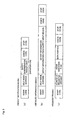
- the safety information is transmitted at timing shown in, for example, Fig. 12 .
- an input data request command is sent from the OUT slave 2" to the IN slave 2'.
- a type of a mode that is, whether or not the mode is a result notification mode or a detailed information notification mode is also sent together with the input data request command.
- the IN slave 2' which has received the command, returns a response in a designated mode. That is, when the IN slave 2' receives an input data (result notification) command, it returns a result notification response that shows a result of the safety information by two bits. Further, when the IN slave 2' receives an input data (detailed information 1) command, it returns a detailed information 1 response for eight channels (2 bytes) as the safety information.
- the OUT slave 2" which has received the respective responses, returns an acknowledgement (ACK) to the IN slave 2'.
- ACK acknowledgement
- other device uses the network during the period of time from the return of the ACK from the OUT slave 2" to the issue of a next input data request command.
- the IN slave 2' switches the result notification mode and the detailed information mode. That is, a condition under which a certain mode is used in transmission is also registered previously, and which of the modes is to be used is determined from a present state according to the condition, and a notification frame is created in correspondence to the determined mode and transmitted.
- the condition is set, for example, such that the result notification mode is ordinarily employed, and when the result notification frame is transmitted a predetermined number of times, transmission can be executed in the detailed information mode. Further, it is also possible to determine a mode based on information abstracted at the time.
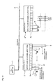
- the mode may be also switched according to a command from the OUT slave. That is, as shown in Fig. 14 , the IN slave 2' ordinarily creates a result notification frame in response to the occurrence of a trigger and transmits the result notification frame. The OUT slave 2" returns an ACK frame in response the result notification frame received thereby.
- the ACK frame including the mode indication flag may employ a structure as shown in Fig. 15 .
- a "safety flag" is prepared as the mode indication flag, and when the safety flag is set to 1, it means a result notification request (refer to Fig. 15(a) ), whereas when the safety flag is set to 0, it means a detailed information notification request (refer to Fig. 15(b) ).
- a safety flag showing a present state.
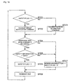
- the MPU operates as described below on the basis of the above premise. That is, first, the MPU determines whether or not the flag is set to "1" (ST21). When the flag is set to "1", since the system is in the safe state and operates normally, the MPU transmits the result notification request command to the IN slave 2' to prepare the occurrence of an abnormal state (dangerous state) (ST22).
- the MPU waits to receive a safety response from the IN slave 2' (ST24), and when the MPU normally receives the response, it determines whether or not the received safety information is safe (ST25). When the safety information is safe, the MPU sets the safety flag to 1 (ST26). Whereas, when the MPU cannot normally receive the safety response (No at step ST24), and when the contents of the received safety information show are the dangerous state, the MPU sets a network abnormal flag to 1 as well as sets the safety flag to "0" (ST27).
- a case that the MPU cannot normally receive the safety response and the determination at step ST24 is branched to No includes (1) a communication error such as noise and the like, (2) a communication error on a transmission side, or a reception side (which can be recovered), (3) removal or interruption of a communication line, (4) a malfunction of the transmitting function of a slave, (5) a malfunction of the receiving function of the master (safety PLC), and the like.
- the safety response can be normally received in a subsequent communication cycle and a communication can be continued.
- the safety PLC cannot receive the safety response of any one of the modes.
- step 1 when the determination at step 1 is branched to No, since the abnormal state (dangerous state) occurred in the past communication cycles and the safety flag has been updated to "0" through step S7, the detailed information command is transmitted to the IN slave 2' (ST23), and the safety information of each safety device is collected. After the safety flag is registered at step 26 or 27, the MPU returns an ACK to the IN slave 2'. Then, the MPU repeats the above processings.
- the processing function of the MPU of the OUT slave 2" is as shown in the flowchart of Fig. 17 . That is, first, the MPU determines whether or not it normally receives the notification frame of the safety information from the IN slave (ST31). When the MPU normally receives the notification frame, it determines whether or not the contents of the safety information sent thereto are "safe" (ST32). When the contents of the safety information are safe, the MPU sets the safety flag to 1, whereas when they are not safe, the MPU sets the network abnormal flag to 1 as well as sets the safety flag to 0 (ST34). Note that when the notification frame cannot be normally received (determination at step 31 is branched to No), the processing at step 34 is also executed.
- the safety flag is set to an ACK frame.
- any one of the ACK frames shown in Fig. 15 is created.
- the MPU returns an ACK with the safety flag to the IN slave 2' (ST36). Then, the MPU repeats the above processings.
- the processing function of the MPU of the OUT slave 2" is as shown below. That is, first, the MPU receives the notification frame of the safety information from the IN slave. Next, when the MPU normally receives the notification frame, it transmits an ACK to the IN slave. Then, the MPU repeats the above processings.
- the MPU of the OUT slave 2" receives the safety information, which indicates "not safe (dangerous)" from the IN slave 2', the MPU executes a desired failsafe processing by stopping an output device, and the like.
- the safety information can be obtained promptly because it can be directly obtained from the IN slave without passing through the master. Accordingly, a period of time from the occurrence of the abnormal state to the operation of failsafe function can be reduced.
- the MPU 23 determines whether or not a transmission condition is satisfied (ST41).
- the external trigger it is determined that the transmission condition is satisfied when the MPU 23 receives an input request command from, for example, the OUT slave.
- the internal trigger it is determined that the transmission condition is satisfied when an internal timer measures a predetermined time or when a condition event occurs.
- the MPU 23 determines whether or not the result notification mode is employed (ST42). This determination can be made depending on whether or not the safety flag is set to 1.
- the result notification mode is employed, the result of arithmetic operation of a safety I/O input (2 bits) is set to a transmission buffer (ST43).
- the safety I/O input (2 bytes) is set to the transmission buffer before it is subjected to the arithmetic operation (ST45, ST46). Note that when any of the above modes is not employed, the MPU 23 returns to step 41 and waits that a next transmission condition is satisfied.
- the MPU 23 After the MPU 23 executes the processing at step 43 or 46 and sets the safety information to the transmission buffer, it transmits the safety information to the OUT slave (ST44). As described above, when the OUT slave 2 receives the safety information, it returns the ACK to the MPU 23. Thus, the MPU 23 determines whether or not it receives the ACK (ST47). When the MPU 23 receives the ACK, it returns to step S41 and waits that a next transmission condition is satisfied. Further, when the MPU 23 does not receive the ACK, the MPU 23 executes a predetermined abnormality processing (ST48).
- this embodiment shows the example that the safety information is transmitted from the IN slave to the OUT slave
- the combination of the slaves when the safety information is sent to nodes other than the master node is not limited to the above combination and can be set arbitrarily selected.
- embodiments described above may be executed independently or a plurality of embodiments may be executed in combination.
- a certain IN slave may transmit the safety information to the OUT slave in an event mode while executing transmission ordinarily in the master/slave system.
- the safety slave determines whether or not the safety condition is satisfied based on a plurality of the safety input informations and returns the result of determination of safety to the safety controller as the safety response. Accordingly, the safety slave can promptly transmit the information whether or not the safety devices (safety slaves) are safe to the master (safety controller) and other devices. As a result, the failsafe function can be promptly executed when an abnormal (dangerous) state occurs.
Landscapes
- Engineering & Computer Science (AREA)
- Physics & Mathematics (AREA)
- General Physics & Mathematics (AREA)
- Automation & Control Theory (AREA)
- Computer Networks & Wireless Communication (AREA)
- Signal Processing (AREA)
- Power Engineering (AREA)
- Programmable Controllers (AREA)
- Safety Devices In Control Systems (AREA)
- Small-Scale Networks (AREA)
Claims (4)
- Sicherheits-Slave (2), welcher für eine Verbindung mit einem Sicherheitsnetzwerk und ein Senden von Informationen, die auf einer Anzahl von aus angesammelten Daten zusammengesetzten Sicherheitsmformattonsemgaben, verwalten durch den Sicherheits-Slave (2), beruhen, an einen mit dem Sicherheitsnetzwerk verbundenen Sicherheits-Controller (1) eingerichtet ist, wobei der Sicherheits-Slave aufweist:Sicherheitsfeststellungsmittel zur Feststellung, beruhend auf der Anwahl von Sicherheitsinformationseingaben, ob eine Sicherheitsbedingung erfüllt ist oder nicht, dadurch gekennzeichnet, dass der Sicherheits-Slave ferner aufweist:eignen Ergebnismitteilungsmodus zum Senden eines durch die Sicherheitsfeststellungsmittel festgestellten Sicherheitsfeststellungsergebnisses als die Informations an den Sicherheits-Controller (1), undeinen Detailinformationsmodus zum Senden der Sicherheitsinformationseingaben so, wie sie sind, als die Information an den Sicherheits-Controller (1),wobei der Ergebnismitteilungsmodus und der Detailinformationssendemodus für ein Umschalten zwischen den Modern, beruhend auf einem von dem Sicherheits-Controller (1) über das Sicherheitsnetzwerk gesendeten Kommunikationsbefehl oder beruhend auf Einstellschaltermitteln, die der Sicherheits-Slave (2) enthält, eingerichtet sind.
- Sicherheits-Slave nach Anspruch 1, wobei der Sicherheits-Slave (2) für eine Feststellung der Gefahrenursache des Sicherheits-Slave (2) selbst und/oder von vom Sicherheits-Slave verwalteten Vorrichtungen und für ein Senden von Daten, die die so festgestellte Gefahrenursache durch Hinzufügen der Daten zu der Information angeben, eingerichtet ist.
- Sicherheits-Slave nach Anspruch 1, wobei das Sicherheitsnetzwerk ein Feldbus und der Sicherheits-Slave eine Sicherheitsüberleiteinrichtung für den Feldbus und eine Art von Feldbus, die von diesem verschieden ist, ist.
- Sicherheits-Slave nach Anspruch 3, wobei
die Sicherheitsinformationseingaben eine Anwahl von Sicherheitsinformationseingaben einer Anzahl von mit der Sicherheitsüberleiteinrichtung verbundenen anderen Sicherheits-Slaves umfassen; und wobei
die Sicherheitsüberleiteinrichtung für ein Senden der Anzahl von Sicherheitsinformationseingaben, die in jeder bestimmten Einheit gewonnen sind, im Timesharing eingerichtet ist.
Priority Applications (1)
| Application Number | Priority Date | Filing Date | Title |
|---|---|---|---|
| EP10177156A EP2256562B1 (de) | 2001-06-22 | 2002-06-21 | Sicherheitssteuerung |
Applications Claiming Priority (3)
| Application Number | Priority Date | Filing Date | Title |
|---|---|---|---|
| JP2001190417 | 2001-06-22 | ||
| JP2001190417 | 2001-06-22 | ||
| PCT/JP2002/006241 WO2003001306A1 (fr) | 2001-06-22 | 2002-06-21 | Systeme de reseau securise, esclave securise et controleur securise |
Related Child Applications (1)
| Application Number | Title | Priority Date | Filing Date |
|---|---|---|---|
| EP10170856.8 Division-Into | 2010-07-27 |
Publications (3)
| Publication Number | Publication Date |
|---|---|
| EP1406134A1 EP1406134A1 (de) | 2004-04-07 |
| EP1406134A4 EP1406134A4 (de) | 2006-02-01 |
| EP1406134B1 true EP1406134B1 (de) | 2010-10-06 |
Family
ID=19029188
Family Applications (2)
| Application Number | Title | Priority Date | Filing Date |
|---|---|---|---|
| EP10177156A Expired - Lifetime EP2256562B1 (de) | 2001-06-22 | 2002-06-21 | Sicherheitssteuerung |
| EP02738778A Expired - Lifetime EP1406134B1 (de) | 2001-06-22 | 2002-06-21 | Sicherheitsnetzwerksystem, sicherheits-slave und sicherheitssteuerung |
Family Applications Before (1)
| Application Number | Title | Priority Date | Filing Date |
|---|---|---|---|
| EP10177156A Expired - Lifetime EP2256562B1 (de) | 2001-06-22 | 2002-06-21 | Sicherheitssteuerung |
Country Status (5)
| Country | Link |
|---|---|
| US (1) | US7120505B2 (de) |
| EP (2) | EP2256562B1 (de) |
| JP (1) | JP3912378B2 (de) |
| DE (1) | DE60237888D1 (de) |
| WO (1) | WO2003001306A1 (de) |
Families Citing this family (44)
| Publication number | Priority date | Publication date | Assignee | Title |
|---|---|---|---|---|
| US7430451B2 (en) * | 2001-05-31 | 2008-09-30 | Omron Corporation | Safety unit, controller system, connection method of controllers, control method of the controller system and monitor method of the controller system |
| CN1259601C (zh) * | 2001-05-31 | 2006-06-14 | 欧姆龙株式会社 | 从动设备、网络系统、从动设备的处理方法及设备信息收集方法 |
| JP3748077B2 (ja) * | 2001-05-31 | 2006-02-22 | オムロン株式会社 | 安全ネットワークシステム及び安全スレーブ並びに安全コントローラ及び通信方法並びに安全ネットワークシステムにおける情報収集方法及びモニタ方法 |
| EP1404061B1 (de) * | 2001-06-22 | 2011-08-10 | Omron Corporation | Sicherheitsnetzwerksystem und sicherheits-slave |
| US7050860B2 (en) * | 2001-06-22 | 2006-05-23 | Omron Corporation | Safety network system, safety slave, and communication method |
| US7007107B1 (en) * | 2001-10-22 | 2006-02-28 | United Electronic Industries | Methods and apparatus for performing data acquisition and control |
| JP4062492B2 (ja) * | 2002-03-07 | 2008-03-19 | オムロン株式会社 | 安全条件設定支援装置及びプログラム並びに記録媒体 |
| US7076311B2 (en) * | 2002-07-09 | 2006-07-11 | Rockwell Automation Technologies, Inc. | Configurable safety system for implementation on industrial system and method of implementing same |
| JP3988559B2 (ja) * | 2002-07-18 | 2007-10-10 | オムロン株式会社 | 通信システム、通信装置及び通信制御方法 |
| US7237102B2 (en) * | 2002-10-30 | 2007-06-26 | Intel Corporation | Methods and apparatus for configuring hardware resources in a pre-boot environment without requiring a system reset |
| DE10301504B3 (de) * | 2003-01-17 | 2004-10-21 | Phoenix Contact Gmbh & Co. Kg | Einsignalübertragung sicherer Prozessinformation |
| US7610119B2 (en) * | 2003-07-08 | 2009-10-27 | Omron Corporation | Safety controller and system using same |
| JP3944156B2 (ja) * | 2003-12-03 | 2007-07-11 | ファナック株式会社 | 非常停止回路 |
| US20050216101A1 (en) * | 2004-03-15 | 2005-09-29 | Omron Corporation | Analog input slave and monitoring system |
| EP1645922B1 (de) * | 2004-10-08 | 2009-08-05 | Rockwell Automation Germany GmbH & Co. KG | Modulares und konfigurierbares Sicherheitssystem |
| DE602006017460D1 (de) * | 2005-03-14 | 2010-11-25 | Omron Tateisi Electronics Co | Programmierbares Steuersystem |
| US8055814B2 (en) * | 2005-03-18 | 2011-11-08 | Rockwell Automation Technologies, Inc. | Universal safety I/O module |
| JP3978617B2 (ja) * | 2005-04-19 | 2007-09-19 | オムロン株式会社 | 安全ユニットの入力装置 |
| JP4619231B2 (ja) * | 2005-07-29 | 2011-01-26 | 株式会社ジェイテクト | 安全plc |
| DE102006002824B4 (de) * | 2006-01-19 | 2008-10-09 | Phoenix Contact Gmbh & Co. Kg | Verfahren und Vorrichtung zur Umwandlung mehrkanalig vorliegender Nachrichten in eine einkanalige sichere Nachricht |
| DE102006013578B4 (de) * | 2006-03-22 | 2008-03-27 | Phoenix Contact Gmbh & Co. Kg | Verfahren und Steuer- und Datenübertragungsanlage zum Überprüfen des Einbauortes eines sicheren Kommunikationsteilnehmers |
| DE102006030114B4 (de) * | 2006-06-28 | 2010-09-09 | Phoenix Contact Gmbh & Co. Kg | Sichere Eingangsschaltung mit einkanaligem Peripherieanschluss für den Eingang eines Busteilnehmers |
| US20080273527A1 (en) * | 2007-05-03 | 2008-11-06 | The University Of Leicester | Distributed system |
| US7624219B2 (en) | 2007-08-09 | 2009-11-24 | Ifm Electronic Gmbh | Bus node |
| DE102008007672B4 (de) * | 2008-01-25 | 2016-09-22 | Pilz Gmbh & Co. Kg | Verfahren und Vorrichtung zum Übertragen von Daten in einem Netzwerk |
| EP2219089A1 (de) * | 2009-02-02 | 2010-08-18 | Siemens Aktiengesellschaft | Verfahren zum Betrieb eines Automatisierungssystems, korrespondierendes Computerprogramm und Automatisierungsgerät in einem Automatisierungssystem, das ein solches Computerprogramm ausführt |
| ATE540343T1 (de) * | 2009-10-23 | 2012-01-15 | Sick Ag | Sicherheitssteuerung |
| AT509310B1 (de) * | 2009-12-16 | 2015-10-15 | Bachmann Gmbh | Verfahren zum betrieb einer speicherprogrammierbaren steuerung (sps) mit dezentraler, autonomer ablaufsteuerung |
| US8514054B2 (en) | 2010-01-22 | 2013-08-20 | Aramark Uniform & Career Apparell Group, Inc. | Personnel key tracking system |
| CN103141048A (zh) * | 2010-08-03 | 2013-06-05 | 大陆-特韦斯贸易合伙股份公司及两合公司 | 利用回波的通信方法 |
| RU2450337C1 (ru) * | 2011-05-03 | 2012-05-10 | Государственное казенное образовательное учреждение высшего профессионального образования Академия Федеральной службы охраны Российской Федерации (Академия ФСО России) | Способ (варианты) управления демаскирующими признаками системы связи |
| DE102011107323A1 (de) * | 2011-07-06 | 2013-01-10 | Abb Ag | Verfahren zur Übertragung eines Prozessabbildes über ein Gateway-Gerät |
| CN104025095B (zh) * | 2011-10-05 | 2018-10-19 | 奥普唐公司 | 用于监视和/或生成动态环境的方法、装置和系统 |
| US8806209B2 (en) * | 2012-12-22 | 2014-08-12 | Wigwag, Llc | Provisioning of electronic devices |
| JP6225244B2 (ja) * | 2013-03-12 | 2017-11-01 | サウジ アラビアン オイル カンパニー | 油田処理制御システム |
| DE112014006106B4 (de) * | 2014-03-06 | 2022-03-17 | Mitsubishi Electric Corporation | Sicherheitssteuersystem und Sicherheitssteuergerät |
| DE102014103135B3 (de) * | 2014-03-10 | 2015-03-19 | Phoenix Contact Gmbh & Co. Kg | System zur sicheren Steuerung von Maschinen, Anlagen oder dergleichen |
| KR20170114643A (ko) * | 2016-04-05 | 2017-10-16 | 엘에스산전 주식회사 | Plc용 통신 시스템 |
| JP6977265B2 (ja) | 2017-01-27 | 2021-12-08 | オムロン株式会社 | マスタースレーブ制御システム、およびマスタースレーブ制御システムの制御方法 |
| KR20180124340A (ko) * | 2017-05-11 | 2018-11-21 | 엘에스산전 주식회사 | 프로그래머블 논리 제어 장치 |
| JP6969371B2 (ja) * | 2017-12-28 | 2021-11-24 | オムロン株式会社 | 制御システムおよび制御装置 |
| JP6856048B2 (ja) * | 2018-04-03 | 2021-04-07 | オムロン株式会社 | 制御システムおよび制御方法 |
| JP7292558B1 (ja) * | 2021-05-11 | 2023-06-16 | 三菱電機株式会社 | ゲートウェイ装置、ゲートウェイ制御方法、及び、ゲートウェイ制御プログラム |
| WO2024209501A1 (ja) * | 2023-04-03 | 2024-10-10 | 三菱電機株式会社 | ゲートウェイ装置、中継方法及び中継プログラム |
Family Cites Families (45)
| Publication number | Priority date | Publication date | Assignee | Title |
|---|---|---|---|---|
| US4625308A (en) * | 1982-11-30 | 1986-11-25 | American Satellite Company | All digital IDMA dynamic channel allocated satellite communications system and method |
| JPS6062482A (ja) | 1983-09-02 | 1985-04-10 | フアナツク株式会社 | ロボットの安全速度制御装置 |
| US4715031A (en) * | 1985-09-23 | 1987-12-22 | Ford Motor Company | Vehicular data transfer communication system |
| US4750171A (en) * | 1986-07-11 | 1988-06-07 | Tadiran Electronics Industries Ltd. | Data switching system and method |
| JPH0670820B2 (ja) | 1989-09-29 | 1994-09-07 | 株式会社シーエスケイ | 自動販売機データ収集システム |
| US5218680A (en) * | 1990-03-15 | 1993-06-08 | International Business Machines Corporation | Data link controller with autonomous in tandem pipeline circuit elements relative to network channels for transferring multitasking data in cyclically recurrent time slots |
| JPH0445697A (ja) | 1990-06-13 | 1992-02-14 | Nec Corp | ポーリング方式 |
| JPH0537980A (ja) | 1991-07-29 | 1993-02-12 | Mitsubishi Electric Corp | プラント監視装置 |
| GB2267984A (en) | 1992-06-16 | 1993-12-22 | Thorn Emi Electronics Ltd | Multiplexing bus interface. |
| US5434872A (en) * | 1992-07-28 | 1995-07-18 | 3Com Corporation | Apparatus for automatic initiation of data transmission |
| US5400018A (en) * | 1992-12-22 | 1995-03-21 | Caterpillar Inc. | Method of relaying information relating to the status of a vehicle |
| JPH06324719A (ja) * | 1993-05-14 | 1994-11-25 | Omron Corp | プログラマブルコントローラ |
| JPH07282090A (ja) * | 1994-04-14 | 1995-10-27 | Toshiba Corp | データ収集方式 |
| JPH08211792A (ja) | 1995-02-03 | 1996-08-20 | Mita Ind Co Ltd | 画像形成装置の管理システム |
| DE19516938C1 (de) * | 1995-05-09 | 1996-12-19 | Leuze Electronic Gmbh & Co | Sensor-Aktuator-Bussystem |
| JP3282470B2 (ja) | 1995-11-08 | 2002-05-13 | 三菱電機株式会社 | パソコンを用いた数値制御装置及びその制御方法 |
| JPH09161181A (ja) * | 1995-12-12 | 1997-06-20 | Toshiba Corp | 自動表示装置 |
| DE19629868A1 (de) | 1996-07-24 | 1998-02-05 | Kloeckner Moeller Gmbh | Verfahren zur Übertragung binärer Daten und Schnittstellenbausteine zur Durchführung des Verfahrens |
| US6098109A (en) * | 1996-12-30 | 2000-08-01 | Compaq Computer Corporation | Programmable arbitration system for determining priority of the ports of a network switch |
| US5907689A (en) * | 1996-12-31 | 1999-05-25 | Compaq Computer Corporation | Master-target based arbitration priority |
| DE19718284C2 (de) * | 1997-05-01 | 2001-09-27 | Kuka Roboter Gmbh | Verfahren und Vorrichtung zum Überwachen einer Anlage mit mehreren Funktionseinheiten |
| JP3485444B2 (ja) | 1997-07-09 | 2004-01-13 | 新キャタピラー三菱株式会社 | 移動式作業機械管理システム及び管理方法並びに同管理システムのための移動式作業機械,ユーザ装置及び親装置 |
| US6574234B1 (en) * | 1997-09-05 | 2003-06-03 | Amx Corporation | Method and apparatus for controlling network devices |
| USH1882H (en) * | 1997-09-26 | 2000-10-03 | Asthana; Sarvesh | System and method for transferring data to redundant components |
| DE19742716C5 (de) | 1997-09-26 | 2005-12-01 | Phoenix Contact Gmbh & Co. Kg | Steuer- und Datenübertragungsanlage und Verfahren zum Übertragen von sicherheitsbezogenen Daten |
| US6640268B1 (en) * | 1998-08-28 | 2003-10-28 | Intel Corporation | Dynamic polling mechanism for wireless devices |
| JP3663617B2 (ja) | 1999-03-12 | 2005-06-22 | オムロン株式会社 | Plc用ツール装置、並びに、プログラム記録媒体 |
| JP3794459B2 (ja) | 1999-03-17 | 2006-07-05 | オムロン株式会社 | データ伝送システム並びに通信ユニット及び機器 |
| DE19921846A1 (de) * | 1999-05-11 | 2000-11-23 | Bosch Gmbh Robert | Diagnosetestvorrichtung mit portablem Prüfgerät für Kraftfahrzeuge |
| DE50014879D1 (de) * | 1999-08-13 | 2008-02-07 | Fraunhofer Ges Forschung | Haus-kommunikationssystem, transportplattform für ein haus-kommunikationssystem und intelligentes netzabschlussgerät für ein haus-kommunikationssystem |
| JP4176252B2 (ja) | 1999-09-14 | 2008-11-05 | 株式会社イシダ | 商品処理装置のメンテナンスシステム |
| JP2001084014A (ja) | 1999-09-16 | 2001-03-30 | Nippon Signal Co Ltd:The | 生産設備制御システム |
| US6532550B1 (en) * | 2000-02-10 | 2003-03-11 | Westinghouse Electric Company Llc | Process protection system |
| JP3827928B2 (ja) * | 2000-08-25 | 2006-09-27 | Ntn株式会社 | 機械部品の監視システム |
| JP2002073121A (ja) * | 2000-08-24 | 2002-03-12 | Fuji Electric Co Ltd | ネットワーク制御システム、その通信モジュール、及びリモート制御方法 |
| KR100626675B1 (ko) * | 2000-12-21 | 2006-09-22 | 삼성전자주식회사 | 무선 통신기기 및 그 제어방법 |
| GB2371449A (en) * | 2001-01-22 | 2002-07-24 | Nokia Mobile Phones Ltd | Synchronizing a new device to a synchronized network of devices |
| JP3748077B2 (ja) | 2001-05-31 | 2006-02-22 | オムロン株式会社 | 安全ネットワークシステム及び安全スレーブ並びに安全コントローラ及び通信方法並びに安全ネットワークシステムにおける情報収集方法及びモニタ方法 |
| US7430451B2 (en) * | 2001-05-31 | 2008-09-30 | Omron Corporation | Safety unit, controller system, connection method of controllers, control method of the controller system and monitor method of the controller system |
| CN1259601C (zh) * | 2001-05-31 | 2006-06-14 | 欧姆龙株式会社 | 从动设备、网络系统、从动设备的处理方法及设备信息收集方法 |
| JP3906840B2 (ja) * | 2001-06-08 | 2007-04-18 | オムロン株式会社 | セーフティネットワークシステム |
| EP1404061B1 (de) * | 2001-06-22 | 2011-08-10 | Omron Corporation | Sicherheitsnetzwerksystem und sicherheits-slave |
| US7050860B2 (en) * | 2001-06-22 | 2006-05-23 | Omron Corporation | Safety network system, safety slave, and communication method |
| JP2003037545A (ja) * | 2001-07-23 | 2003-02-07 | Nec Corp | 近距離無線機能付き移動局及びその消費電力低減方法 |
| JP4048864B2 (ja) | 2002-07-29 | 2008-02-20 | カシオ計算機株式会社 | 小型化学反応装置およびその製造方法 |
-
2002
- 2002-06-21 DE DE60237888T patent/DE60237888D1/de not_active Expired - Lifetime
- 2002-06-21 WO PCT/JP2002/006241 patent/WO2003001306A1/ja active Application Filing
- 2002-06-21 JP JP2003507639A patent/JP3912378B2/ja not_active Expired - Lifetime
- 2002-06-21 EP EP10177156A patent/EP2256562B1/de not_active Expired - Lifetime
- 2002-06-21 EP EP02738778A patent/EP1406134B1/de not_active Expired - Lifetime
- 2002-06-21 US US10/481,516 patent/US7120505B2/en not_active Expired - Lifetime
Also Published As
| Publication number | Publication date |
|---|---|
| EP2256562B1 (de) | 2012-01-25 |
| US7120505B2 (en) | 2006-10-10 |
| WO2003001306A1 (fr) | 2003-01-03 |
| US20040215354A1 (en) | 2004-10-28 |
| DE60237888D1 (de) | 2010-11-18 |
| EP2256562A1 (de) | 2010-12-01 |
| JPWO2003001306A1 (ja) | 2004-10-14 |
| JP3912378B2 (ja) | 2007-05-09 |
| EP1406134A1 (de) | 2004-04-07 |
| EP1406134A4 (de) | 2006-02-01 |
Similar Documents
| Publication | Publication Date | Title |
|---|---|---|
| EP1406134B1 (de) | Sicherheitsnetzwerksystem, sicherheits-slave und sicherheitssteuerung | |
| JP3748078B2 (ja) | 安全ネットワークシステム及び安全スレーブ | |
| EP1396963B1 (de) | Sicherheitsnetzwerksystem und sicherheits-slaves und sicherheitssteuerung und kommunikationsverfahren und informationssammelverfahren und überwachungsverfahren in einem sicherheitsnetzwerksystem | |
| US9934111B2 (en) | Control and data transmission system, process device, and method for redundant process control with decentralized redundancy | |
| EP1396772B1 (de) | Sicherheitseinheit, steuerungsverkettungsverfahren, steuerungssystemsteuerverfahren und steuerungssystemüberwachungsverfahren | |
| JP4338354B2 (ja) | スレーブ | |
| JP3912379B2 (ja) | 安全ネットワークシステム及び安全スレーブ並びに通信方法 | |
| JPWO2002097542A1 (ja) | スレーブ及びネットワークシステム並びにスレーブの処理方法及び機器情報収集方法 | |
| US20030140270A1 (en) | Redundant control system and control computer and peripheral unit for a control system of this type | |
| KR100689323B1 (ko) | 필드버스 네트워크 다중화 시스템 | |
| JP2013201664A (ja) | 冗長通信装置 | |
| US11169491B2 (en) | Safety switch | |
| KR101846222B1 (ko) | 이중화 시스템 및 그의 제어 방법 | |
| KR100932148B1 (ko) | 피엘씨 네트워크의 마스터 모듈 및 슬레이브 모듈 통신 방법 | |
| JP2005259077A (ja) | スレーブおよび監視システム | |
| JP3090816B2 (ja) | 二重化制御システム | |
| JP2023161769A (ja) | 二重化通信インターフェースモジュールの切替方法 | |
| KR20230130710A (ko) | 스위칭 시스템 및 스위치 | |
| KR200403626Y1 (ko) | 통신 시스템의 이중화 제어장치 | |
| JPH0470231A (ja) | ネットワークの二重化システム | |
| JPH03291746A (ja) | 複合計算機システム監視制御方法及び装置 |
Legal Events
| Date | Code | Title | Description |
|---|---|---|---|
| PUAI | Public reference made under article 153(3) epc to a published international application that has entered the european phase |
Free format text: ORIGINAL CODE: 0009012 |
|
| 17P | Request for examination filed |
Effective date: 20040119 |
|
| AK | Designated contracting states |
Kind code of ref document: A1 Designated state(s): AT BE CH CY DE DK ES FI FR GB GR IE IT LI LU MC NL PT SE TR |
|
| AX | Request for extension of the european patent |
Extension state: AL LT LV MK RO SI |
|
| RIC1 | Information provided on ipc code assigned before grant |
Ipc: H04L 12/403 19950101ALI20051207BHEP Ipc: G05B 9/02 19680901AFI20030106BHEP |
|
| A4 | Supplementary search report drawn up and despatched |
Effective date: 20051220 |
|
| 17Q | First examination report despatched |
Effective date: 20070301 |
|
| GRAP | Despatch of communication of intention to grant a patent |
Free format text: ORIGINAL CODE: EPIDOSNIGR1 |
|
| RTI1 | Title (correction) |
Free format text: SAFETY NETWORK SYSTEM, SAFETY SLAVE AND SAFETY CONTROLLER |
|
| GRAS | Grant fee paid |
Free format text: ORIGINAL CODE: EPIDOSNIGR3 |
|
| RIN1 | Information on inventor provided before grant (corrected) |
Inventor name: MUNETA, YASUO Inventor name: NAKAMURA, TOSHIYUKI |
|
| GRAA | (expected) grant |
Free format text: ORIGINAL CODE: 0009210 |
|
| RAP1 | Party data changed (applicant data changed or rights of an application transferred) |
Owner name: OMRON CORPORATION |
|
| RAP1 | Party data changed (applicant data changed or rights of an application transferred) |
Owner name: OMRON CORPORATION |
|
| AK | Designated contracting states |
Kind code of ref document: B1 Designated state(s): DE FR GB IT |
|
| REG | Reference to a national code |
Ref country code: GB Ref legal event code: FG4D |
|
| REF | Corresponds to: |
Ref document number: 60237888 Country of ref document: DE Date of ref document: 20101118 Kind code of ref document: P |
|
| PLBE | No opposition filed within time limit |
Free format text: ORIGINAL CODE: 0009261 |
|
| STAA | Information on the status of an ep patent application or granted ep patent |
Free format text: STATUS: NO OPPOSITION FILED WITHIN TIME LIMIT |
|
| 26N | No opposition filed |
Effective date: 20110707 |
|
| REG | Reference to a national code |
Ref country code: DE Ref legal event code: R097 Ref document number: 60237888 Country of ref document: DE Effective date: 20110707 |
|
| REG | Reference to a national code |
Ref country code: DE Ref legal event code: R082 Ref document number: 60237888 Country of ref document: DE Representative=s name: KILIAN KILIAN & PARTNER MBB PATENTANWAELTE, DE Ref country code: DE Ref legal event code: R082 Ref document number: 60237888 Country of ref document: DE Representative=s name: KILIAN KILIAN & PARTNER, DE |
|
| REG | Reference to a national code |
Ref country code: FR Ref legal event code: PLFP Year of fee payment: 15 |
|
| REG | Reference to a national code |
Ref country code: FR Ref legal event code: PLFP Year of fee payment: 16 |
|
| REG | Reference to a national code |
Ref country code: FR Ref legal event code: PLFP Year of fee payment: 17 |
|
| PGFP | Annual fee paid to national office [announced via postgrant information from national office to epo] |
Ref country code: DE Payment date: 20210525 Year of fee payment: 20 Ref country code: FR Payment date: 20210513 Year of fee payment: 20 Ref country code: IT Payment date: 20210511 Year of fee payment: 20 |
|
| PGFP | Annual fee paid to national office [announced via postgrant information from national office to epo] |
Ref country code: GB Payment date: 20210526 Year of fee payment: 20 |
|
| REG | Reference to a national code |
Ref country code: DE Ref legal event code: R071 Ref document number: 60237888 Country of ref document: DE |
|
| REG | Reference to a national code |
Ref country code: GB Ref legal event code: PE20 Expiry date: 20220620 |
|
| PG25 | Lapsed in a contracting state [announced via postgrant information from national office to epo] |
Ref country code: GB Free format text: LAPSE BECAUSE OF EXPIRATION OF PROTECTION Effective date: 20220620 |