EP1405993A2 - Système d'admission pour moteur à combustion interne - Google Patents
Système d'admission pour moteur à combustion interne Download PDFInfo
- Publication number
- EP1405993A2 EP1405993A2 EP20030022571 EP03022571A EP1405993A2 EP 1405993 A2 EP1405993 A2 EP 1405993A2 EP 20030022571 EP20030022571 EP 20030022571 EP 03022571 A EP03022571 A EP 03022571A EP 1405993 A2 EP1405993 A2 EP 1405993A2
- Authority
- EP
- European Patent Office
- Prior art keywords
- passage section
- intake
- motion control
- control valve
- gas motion
- Prior art date
- Legal status (The legal status is an assumption and is not a legal conclusion. Google has not performed a legal analysis and makes no representation as to the accuracy of the status listed.)
- Granted
Links
- 238000005192 partition Methods 0.000 claims abstract description 59
- 238000011144 upstream manufacturing Methods 0.000 claims abstract description 46
- 238000002485 combustion reaction Methods 0.000 claims abstract description 20
- 238000005266 casting Methods 0.000 claims description 4
- 230000001105 regulatory effect Effects 0.000 claims description 4
- 230000003134 recirculating effect Effects 0.000 claims description 2
- 230000000052 comparative effect Effects 0.000 description 8
- 239000012530 fluid Substances 0.000 description 8
- 230000003247 decreasing effect Effects 0.000 description 6
- 238000010586 diagram Methods 0.000 description 1
- 230000000694 effects Effects 0.000 description 1
- 239000000446 fuel Substances 0.000 description 1
- 238000002347 injection Methods 0.000 description 1
- 239000007924 injection Substances 0.000 description 1
- 239000002184 metal Substances 0.000 description 1
- 239000000203 mixture Substances 0.000 description 1
- 230000004048 modification Effects 0.000 description 1
- 238000012986 modification Methods 0.000 description 1
- 238000005728 strengthening Methods 0.000 description 1
Images


Classifications
-
- F—MECHANICAL ENGINEERING; LIGHTING; HEATING; WEAPONS; BLASTING
- F02—COMBUSTION ENGINES; HOT-GAS OR COMBUSTION-PRODUCT ENGINE PLANTS
- F02F—CYLINDERS, PISTONS OR CASINGS, FOR COMBUSTION ENGINES; ARRANGEMENTS OF SEALINGS IN COMBUSTION ENGINES
- F02F1/00—Cylinders; Cylinder heads
- F02F1/24—Cylinder heads
- F02F1/42—Shape or arrangement of intake or exhaust channels in cylinder heads
- F02F1/4235—Shape or arrangement of intake or exhaust channels in cylinder heads of intake channels
- F02F1/4242—Shape or arrangement of intake or exhaust channels in cylinder heads of intake channels with a partition wall inside the channel
-
- F—MECHANICAL ENGINEERING; LIGHTING; HEATING; WEAPONS; BLASTING
- F02—COMBUSTION ENGINES; HOT-GAS OR COMBUSTION-PRODUCT ENGINE PLANTS
- F02B—INTERNAL-COMBUSTION PISTON ENGINES; COMBUSTION ENGINES IN GENERAL
- F02B31/00—Modifying induction systems for imparting a rotation to the charge in the cylinder
- F02B31/04—Modifying induction systems for imparting a rotation to the charge in the cylinder by means within the induction channel, e.g. deflectors
-
- F—MECHANICAL ENGINEERING; LIGHTING; HEATING; WEAPONS; BLASTING
- F02—COMBUSTION ENGINES; HOT-GAS OR COMBUSTION-PRODUCT ENGINE PLANTS
- F02B—INTERNAL-COMBUSTION PISTON ENGINES; COMBUSTION ENGINES IN GENERAL
- F02B31/00—Modifying induction systems for imparting a rotation to the charge in the cylinder
- F02B31/08—Modifying induction systems for imparting a rotation to the charge in the cylinder having multiple air inlets
-
- Y—GENERAL TAGGING OF NEW TECHNOLOGICAL DEVELOPMENTS; GENERAL TAGGING OF CROSS-SECTIONAL TECHNOLOGIES SPANNING OVER SEVERAL SECTIONS OF THE IPC; TECHNICAL SUBJECTS COVERED BY FORMER USPC CROSS-REFERENCE ART COLLECTIONS [XRACs] AND DIGESTS
- Y02—TECHNOLOGIES OR APPLICATIONS FOR MITIGATION OR ADAPTATION AGAINST CLIMATE CHANGE
- Y02T—CLIMATE CHANGE MITIGATION TECHNOLOGIES RELATED TO TRANSPORTATION
- Y02T10/00—Road transport of goods or passengers
- Y02T10/10—Internal combustion engine [ICE] based vehicles
- Y02T10/12—Improving ICE efficiencies
Definitions
- Gas motion in engine cylinder such as tumble or swirl is one of important factors to achieve stable combustion of diluted air/fuel mixture in a spark ignition internal combustion engine. Accordingly, engines of some types require an intake system which can increase incylinder gas motion in wider engine operating region.
- Such a gas motion control valve is arranged to produce an incylinder tumbling flow by decreasing an open area ratio that is a ratio of an effective flow passage sectional area to an entire flow passage area of an intake port.
- an open area ratio that is a ratio of an effective flow passage sectional area to an entire flow passage area of an intake port.
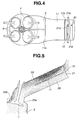
- FIG. 4 is a plan view of the intake apparatus of FIG. 3 as viewed from above.
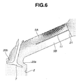
- FIGS. 5 and 6 are schematic sectional views illustrating intake air streams in an intake port in the example of FIG. 3, and in an intake port in a comparative example.
- FIG. 8 is a graph showing a tumble ratio in the example of FIG. 3 in comparison with the comparative example.
- FIG. 12 is a sectional view showing an intake apparatus according to a fourth embodiment of the invention.
- the intake apparatus shown in FIGS. 1 and 2 includes a partition 11 extending in the longitudinal direction of intake port 5 and dividing the cross section of intake port 5 into an upper region and a lower region.
- partition 11 is a metal plate formed as an insert in an operation of casting cylinder head 3, and completed as an integral part of the casting.
- a downstream end 11a of partition 11 is located near intake valve 7.
- the portion of intake port 5 receiving partition 11 extends straight in the longitudinal direction of intake port 5, and accordingly partition 11 is in the form of a flat plate extending straight in the longitudinal direction of intake port 5.
- intake port 5 may be curved, and partition 11 may be curved along the curved section of intake port 5.
- connection passage 12 is opened in an upstream end portion of partition 11 near the upstream end 11b.
- connection passage 12 is in the form of a slit extending in the direction of the cylinder row (in a direction perpendicular to the longitudinal direction of intake port 5).
- the thus-constructed intake system is operated as follows: On intake stroke, intake valve 7 is opened and piston 10 descends in the downward direction in cylinder 2. In this case, intake air flows into cylinder 2 through an open aperture around intake valve 7. If, in this case, gas motion control valve 21 is in the open position, intake air flows through both of upper and lower passage sections 5A and 5B, and the intake air flows into cylinder 2 uniformly around intake valve 7. Therefore, the incylinder gas flow is relatively weak.
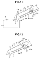
- FIG. 11 shows an intake apparatus according to a third embodiment of the present invention.
- a partition 11 is formed at a lower position in intake port 5, so that the cross sectional area of first passage section 5A on the upper side is greater than that of second passage section 5B on the lower side.
- a valve shaft 21a of a gas motion control valve 21 is located on an extension of partition 11 at a position slightly spaced from the upstream end 11b of partition 11.
- the interspace between the upstream end 11b of partition 11 and valve shaft 21a of gas motion control valve 21 is opened as connection passage 12 when gas motion control valve 21 is in the closed position closing second passage section 5B.
- the open area size of intake port 5 is set at a larger value when the second passage section 5B is closed by gas motion control valve 21. Therefore, the intake system according to the third embodiment makes it possible to produce incylinder tumble by closing gas motion control valve 21 in a wider engine operating range.
- plate valve element 21b includes a bent end portion 21c which projects in the downward direction when valve element 21b is in the closed position shown by solid lines in FIG. 12.
- the angle between bent end portion 21c and the main portion of valve element 21b is so set that bent end portion 21c projects in the downstream direction in the closed position.
- gas motion control valve 21 restrains an intake air stream over valve element 21b from flowing around valve element 21b into a region behind valve element 21b, and helps the growth of low pressure region 13 to the downstream side.
- the lower inside wall surface 5b is formed with a recess 22 for receiving the valve element 21b including bent end portion 21c when valve element 21b is in the open position.
- valve element 21b When retracted in recess 22 in the open position, valve element 21b does not disturb the air flow in intake port.
- bent end portion 21c is snugly received in a deep portion of recess 22.
Landscapes
- Engineering & Computer Science (AREA)
- Chemical & Material Sciences (AREA)
- Combustion & Propulsion (AREA)
- Mechanical Engineering (AREA)
- General Engineering & Computer Science (AREA)
- Cylinder Crankcases Of Internal Combustion Engines (AREA)
- Lift Valve (AREA)
- Combustion Methods Of Internal-Combustion Engines (AREA)
- Characterised By The Charging Evacuation (AREA)
Applications Claiming Priority (2)
| Application Number | Priority Date | Filing Date | Title |
|---|---|---|---|
| JP2002290750 | 2002-10-03 | ||
| JP2002290750A JP4045915B2 (ja) | 2002-10-03 | 2002-10-03 | 内燃機関の吸気装置 |
Publications (3)
| Publication Number | Publication Date |
|---|---|
| EP1405993A2 true EP1405993A2 (fr) | 2004-04-07 |
| EP1405993A3 EP1405993A3 (fr) | 2006-01-11 |
| EP1405993B1 EP1405993B1 (fr) | 2012-06-13 |
Family
ID=31987182
Family Applications (1)
| Application Number | Title | Priority Date | Filing Date |
|---|---|---|---|
| EP03022571A Expired - Lifetime EP1405993B1 (fr) | 2002-10-03 | 2003-10-02 | Système d'admission pour moteur à combustion interne |
Country Status (5)
| Country | Link |
|---|---|
| US (1) | US6874465B2 (fr) |
| EP (1) | EP1405993B1 (fr) |
| JP (1) | JP4045915B2 (fr) |
| KR (1) | KR100741234B1 (fr) |
| CN (1) | CN1308578C (fr) |
Cited By (7)
| Publication number | Priority date | Publication date | Assignee | Title |
|---|---|---|---|---|
| EP1632660A2 (fr) * | 2004-09-07 | 2006-03-08 | Nissan Motor Company, Limited | Sytème d'admission d'air d'un moteur à combustion interne |
| FR2895453A1 (fr) * | 2005-12-23 | 2007-06-29 | Renault Sas | Dispositif de repartition et d'admission d'un moteur a combustion interne, permettant de faire varier l'aerodynamique |
| KR100741234B1 (ko) * | 2002-10-03 | 2007-07-19 | 닛산 지도우샤 가부시키가이샤 | 엔진 흡기 장치 |
| WO2007093916A2 (fr) * | 2006-02-17 | 2007-08-23 | Toyota Jidosha Kabushiki Kaisha | Structure d'orifice d'admission de moteur a combustion interne |
| WO2007126113A1 (fr) * | 2006-04-28 | 2007-11-08 | Toyota Jidosha Kabushiki Kaisha | Appareil d'admission d'air pour moteur a combustion interne |
| EP1632659A3 (fr) * | 2004-09-06 | 2011-06-08 | Nissan Motor Co., Ltd. | Structure de prise d'air d'un moteur à combustion interne |
| US20120210979A1 (en) * | 2009-11-05 | 2012-08-23 | Toyota Jidosha Kabushiki Kaisha | Intake apparatus of engine |
Families Citing this family (25)
| Publication number | Priority date | Publication date | Assignee | Title |
|---|---|---|---|---|
| KR100604300B1 (ko) * | 2003-04-03 | 2006-07-31 | 닛산 지도우샤 가부시키가이샤 | 내연 기관의 흡기 시스템 |
| KR100608182B1 (ko) * | 2003-04-03 | 2006-08-08 | 닛산 지도우샤 가부시키가이샤 | 내연 기관용 흡기 장치 |
| JP4412118B2 (ja) * | 2004-09-06 | 2010-02-10 | 日産自動車株式会社 | 内燃機関の吸気装置 |
| JP4529746B2 (ja) * | 2005-03-17 | 2010-08-25 | 日産自動車株式会社 | 内燃機関の吸気装置 |
| JP2006283696A (ja) | 2005-04-01 | 2006-10-19 | Toyota Motor Corp | 内燃機関の吸気装置 |
| CN100572771C (zh) | 2005-04-01 | 2009-12-23 | 丰田自动车株式会社 | 用于内燃机的进气系统 |
| US7128050B1 (en) | 2005-06-16 | 2006-10-31 | Toyota Jidosha Kabushiki Kaisha | Air intake apparatus for internal combustion engine |
| WO2007132311A2 (fr) * | 2006-05-09 | 2007-11-22 | Toyota Jidosha Kabushiki Kaisha | Dispositif de commande d'admission pour moteur à combustion interne |
| EP2031209B1 (fr) * | 2006-05-24 | 2011-07-27 | Toyota Jidosha Kabushiki Kaisha | Dispositif d'admission d'air pour moteur à combustion interne |
| JP5012245B2 (ja) | 2006-07-31 | 2012-08-29 | トヨタ自動車株式会社 | 内燃機関の吸気構造 |
| US7802555B2 (en) * | 2008-03-18 | 2010-09-28 | Yamaha Hatsudoki Kabushiki Kaisha | Intake control device for an engine |
| JP4623206B2 (ja) | 2008-11-20 | 2011-02-02 | 株式会社デンソー | 内燃機関の吸気装置 |
| US8056546B2 (en) * | 2010-03-24 | 2011-11-15 | Ford Global Technologies, Llc | Multi-function throttle valve |
| JP5988236B2 (ja) * | 2011-08-30 | 2016-09-07 | 俊彦 山本 | エンジンの吸気装置 |
| US8997721B2 (en) * | 2011-08-30 | 2015-04-07 | Toshihiko Yamamoto | Intake apparatus of engine |
| JP5971963B2 (ja) * | 2012-02-03 | 2016-08-17 | ダイキョーニシカワ株式会社 | インテークマニホールド及びその弁装置 |
| US9464605B2 (en) * | 2013-08-24 | 2016-10-11 | Lonn M. Peterson | Quad flow torque enhancement flow divider causing improved fuel/air transfer |
| US9903266B2 (en) | 2013-09-04 | 2018-02-27 | Ford Global Technologies, Llc | Flow channeling air intake mixing device for internal combustion engine |
| JP6543123B2 (ja) * | 2015-07-21 | 2019-07-10 | 株式会社Subaru | エンジンの吸気構造 |
| KR101822270B1 (ko) * | 2016-04-05 | 2018-01-26 | 현대자동차주식회사 | 차량의 엔진 흡기 구조 |
| US9664151B1 (en) * | 2016-04-08 | 2017-05-30 | Kao-Shan Lin | Air admission device for combustion equipment |
| US10907573B2 (en) * | 2016-10-21 | 2021-02-02 | Honda Motor Co., Ltd. | Thermally insulated insert member and engine having same |
| KR20180135141A (ko) * | 2017-06-09 | 2018-12-20 | 현대자동차주식회사 | 차량의 흡기조절장치 |
| JP7027862B2 (ja) * | 2017-12-14 | 2022-03-02 | トヨタ紡織株式会社 | 吸気管の接続構造 |
| JP7064364B2 (ja) * | 2018-03-29 | 2022-05-10 | 株式会社Subaru | 内燃機関の吸気装置 |
Citations (3)
| Publication number | Priority date | Publication date | Assignee | Title |
|---|---|---|---|---|
| US4714063A (en) * | 1985-09-17 | 1987-12-22 | Mazda Motor Corporation | Intake system for internal combustion engine |
| EP0391599A2 (fr) * | 1989-04-06 | 1990-10-10 | Ford Motor Company Limited | Système d'admission pour un moteur à combustion interne |
| JPH06159079A (ja) * | 1992-11-26 | 1994-06-07 | Fuji Heavy Ind Ltd | エンジンの吸気装置 |
Family Cites Families (25)
| Publication number | Priority date | Publication date | Assignee | Title |
|---|---|---|---|---|
| US676077A (en) * | 1899-08-23 | 1901-06-11 | Christopher Herbert Oliverson | Speed-varying apparatus. |
| JPS60230531A (ja) * | 1984-04-27 | 1985-11-16 | Mazda Motor Corp | 燃料噴射装置付エンジン |
| JPS62107228A (ja) | 1985-10-31 | 1987-05-18 | Mazda Motor Corp | エンジンの吸気装置 |
| JP2583895Y2 (ja) * | 1991-02-19 | 1998-10-27 | 三菱自動車工業株式会社 | ディーゼルエンジン |
| US5370098A (en) * | 1991-04-20 | 1994-12-06 | Yamaha Hatsudoki Kabushiki Kaisha | Air intake system for gas fueled engine |
| JPH05209582A (ja) * | 1992-01-31 | 1993-08-20 | Mazda Motor Corp | エンジンの吸気装置 |
| US5267543A (en) * | 1992-12-21 | 1993-12-07 | Ford Motor Company | Dual induction system for internal combustion engine |
| JPH06264816A (ja) * | 1993-03-15 | 1994-09-20 | Nissan Motor Co Ltd | 内燃機関のシリンダヘッド |
| JP2594972Y2 (ja) * | 1993-09-29 | 1999-05-24 | 富士重工業株式会社 | エンジンの吸気装置 |
| JPH07119472A (ja) * | 1993-10-19 | 1995-05-09 | Fuji Heavy Ind Ltd | エンジンの吸気装置 |
| JPH08296535A (ja) * | 1995-04-26 | 1996-11-12 | Unisia Jecs Corp | 内燃機関の吸気装置 |
| US5640941A (en) | 1995-12-04 | 1997-06-24 | Ford Motor Company | Internal combustion engine with stratified charge and tumble motion |
| US5878712A (en) * | 1996-09-20 | 1999-03-09 | Fev Motorentechnik Gmbh & Co. Kg | System for the direct injection of fuel in internal-combustion engines |
| JPH11107764A (ja) * | 1997-09-30 | 1999-04-20 | Mazda Motor Corp | エンジンの吸気装置 |
| JPH11166420A (ja) * | 1997-09-30 | 1999-06-22 | Yamaha Motor Co Ltd | エンジンの吸気装置 |
| US6484690B2 (en) * | 1999-01-06 | 2002-11-26 | Hitachi, Ltd. | Control equipment for internal combustion engines |
| JP3671755B2 (ja) * | 1999-08-13 | 2005-07-13 | 日産自動車株式会社 | 直噴式内燃機関の吸気制御装置 |
| JP3671785B2 (ja) * | 1999-12-15 | 2005-07-13 | 株式会社日立製作所 | 筒内噴射型内燃機関の燃料噴射装置 |
| DE10001583C2 (de) * | 2000-01-17 | 2002-03-21 | Bosch Gmbh Robert | Verfahren und Einrichtung zur Funktionsüberwachung eines Gasströmungssteuerorgans, insbesondere einer Drallkappe, bei einer Brennkraftmaschine |
| JP2002038953A (ja) * | 2000-07-25 | 2002-02-06 | Hitachi Ltd | 筒内噴射エンジン |
| JP2002054535A (ja) | 2000-08-08 | 2002-02-20 | Hitachi Ltd | 火花点火機関 |
| DE10163284B4 (de) * | 2000-12-27 | 2005-12-15 | Hyundai Motor Company | Verfahren zum Herstellen eines Variabel-Wirbelströmungs-Erzeugungs-Einlasskanals |
| JP3926989B2 (ja) * | 2001-02-01 | 2007-06-06 | 株式会社日立製作所 | 筒内噴射式火花点火エンジンの制御装置 |
| JP3723086B2 (ja) * | 2001-03-16 | 2005-12-07 | トヨタ自動車株式会社 | 内燃機関の吸気装置 |
| JP4045915B2 (ja) * | 2002-10-03 | 2008-02-13 | 日産自動車株式会社 | 内燃機関の吸気装置 |
-
2002
- 2002-10-03 JP JP2002290750A patent/JP4045915B2/ja not_active Expired - Lifetime
-
2003
- 2003-09-28 CN CNB031602231A patent/CN1308578C/zh not_active Expired - Lifetime
- 2003-10-02 EP EP03022571A patent/EP1405993B1/fr not_active Expired - Lifetime
- 2003-10-02 US US10/676,015 patent/US6874465B2/en not_active Expired - Lifetime
- 2003-10-02 KR KR1020030068549A patent/KR100741234B1/ko active IP Right Grant
Patent Citations (3)
| Publication number | Priority date | Publication date | Assignee | Title |
|---|---|---|---|---|
| US4714063A (en) * | 1985-09-17 | 1987-12-22 | Mazda Motor Corporation | Intake system for internal combustion engine |
| EP0391599A2 (fr) * | 1989-04-06 | 1990-10-10 | Ford Motor Company Limited | Système d'admission pour un moteur à combustion interne |
| JPH06159079A (ja) * | 1992-11-26 | 1994-06-07 | Fuji Heavy Ind Ltd | エンジンの吸気装置 |
Non-Patent Citations (1)
| Title |
|---|
| PATENT ABSTRACTS OF JAPAN vol. 018, no. 491 (M-1672), 13 September 1994 (1994-09-13) & JP 06 159079 A (FUJI HEAVY IND LTD), 7 June 1994 (1994-06-07) * |
Cited By (11)
| Publication number | Priority date | Publication date | Assignee | Title |
|---|---|---|---|---|
| KR100741234B1 (ko) * | 2002-10-03 | 2007-07-19 | 닛산 지도우샤 가부시키가이샤 | 엔진 흡기 장치 |
| EP1632659A3 (fr) * | 2004-09-06 | 2011-06-08 | Nissan Motor Co., Ltd. | Structure de prise d'air d'un moteur à combustion interne |
| EP1632660A2 (fr) * | 2004-09-07 | 2006-03-08 | Nissan Motor Company, Limited | Sytème d'admission d'air d'un moteur à combustion interne |
| EP1632660A3 (fr) * | 2004-09-07 | 2011-06-01 | Nissan Motor Company Limited | Sytème d'admission d'air d'un moteur à combustion interne |
| FR2895453A1 (fr) * | 2005-12-23 | 2007-06-29 | Renault Sas | Dispositif de repartition et d'admission d'un moteur a combustion interne, permettant de faire varier l'aerodynamique |
| WO2007093916A2 (fr) * | 2006-02-17 | 2007-08-23 | Toyota Jidosha Kabushiki Kaisha | Structure d'orifice d'admission de moteur a combustion interne |
| WO2007093916A3 (fr) * | 2006-02-17 | 2007-11-15 | Toyota Motor Co Ltd | Structure d'orifice d'admission de moteur a combustion interne |
| US7938099B2 (en) | 2006-02-17 | 2011-05-10 | Toyota Jidosha Kabushiki Kaisha | Intake port structure of internal combustion engine |
| WO2007126113A1 (fr) * | 2006-04-28 | 2007-11-08 | Toyota Jidosha Kabushiki Kaisha | Appareil d'admission d'air pour moteur a combustion interne |
| US20120210979A1 (en) * | 2009-11-05 | 2012-08-23 | Toyota Jidosha Kabushiki Kaisha | Intake apparatus of engine |
| US9086021B2 (en) * | 2009-11-05 | 2015-07-21 | Toyota Jidosha Kabushiki Kaisha | Intake apparatus of engine |
Also Published As
| Publication number | Publication date |
|---|---|
| EP1405993B1 (fr) | 2012-06-13 |
| CN1493777A (zh) | 2004-05-05 |
| KR20040031607A (ko) | 2004-04-13 |
| KR100741234B1 (ko) | 2007-07-19 |
| JP4045915B2 (ja) | 2008-02-13 |
| US6874465B2 (en) | 2005-04-05 |
| JP2004124836A (ja) | 2004-04-22 |
| CN1308578C (zh) | 2007-04-04 |
| EP1405993A3 (fr) | 2006-01-11 |
| US20040065296A1 (en) | 2004-04-08 |
Similar Documents
| Publication | Publication Date | Title |
|---|---|---|
| US6874465B2 (en) | Engine intake apparatus | |
| US6918372B2 (en) | Intake system of internal combustion engine | |
| US7051702B2 (en) | Intake apparatus for internal combustion engine | |
| US6904891B2 (en) | Intake system of internal combustion engine | |
| US7128050B1 (en) | Air intake apparatus for internal combustion engine | |
| EP1464806B1 (fr) | Dispositif d'admission pour moteur à combustion interne | |
| US6478008B2 (en) | Piston-type internal combustion engine having a subdivided gas-intake port | |
| US6868823B2 (en) | Intake apparatus for internal combustion engine | |
| US6526940B2 (en) | Multiple intake valve engine | |
| EP1344926B1 (fr) | Canal d'admission d'un moteur à combustion interne | |
| US20100037853A1 (en) | Intake system for an internal combustion engine | |
| JP3014802B2 (ja) | エンジンの吸気構造 | |
| JPH0988616A (ja) | 内燃機関の吸気装置 | |
| JP3861837B2 (ja) | 内燃機関の吸気装置 | |
| JP3903941B2 (ja) | 内燃機関の吸気装置 | |
| JP2002180840A (ja) | 内燃機関の吸気ポート構造 |
Legal Events
| Date | Code | Title | Description |
|---|---|---|---|
| PUAI | Public reference made under article 153(3) epc to a published international application that has entered the european phase |
Free format text: ORIGINAL CODE: 0009012 |
|
| 17P | Request for examination filed |
Effective date: 20031002 |
|
| AK | Designated contracting states |
Kind code of ref document: A2 Designated state(s): AT BE BG CH CY CZ DE DK EE ES FI FR GB GR HU IE IT LI LU MC NL PT RO SE SI SK TR |
|
| AX | Request for extension of the european patent |
Extension state: AL LT LV MK |
|
| PUAL | Search report despatched |
Free format text: ORIGINAL CODE: 0009013 |
|
| AK | Designated contracting states |
Kind code of ref document: A3 Designated state(s): AT BE BG CH CY CZ DE DK EE ES FI FR GB GR HU IE IT LI LU MC NL PT RO SE SI SK TR |
|
| AX | Request for extension of the european patent |
Extension state: AL LT LV MK |
|
| RIC1 | Information provided on ipc code assigned before grant |
Ipc: F02B 31/04 19950101AFI20040105BHEP Ipc: F02B 31/08 19950101ALI20051123BHEP |
|
| AKX | Designation fees paid |
Designated state(s): DE FR GB |
|
| 17Q | First examination report despatched |
Effective date: 20061027 |
|
| GRAP | Despatch of communication of intention to grant a patent |
Free format text: ORIGINAL CODE: EPIDOSNIGR1 |
|
| GRAS | Grant fee paid |
Free format text: ORIGINAL CODE: EPIDOSNIGR3 |
|
| GRAA | (expected) grant |
Free format text: ORIGINAL CODE: 0009210 |
|
| AK | Designated contracting states |
Kind code of ref document: B1 Designated state(s): DE FR GB |
|
| REG | Reference to a national code |
Ref country code: GB Ref legal event code: FG4D |
|
| REG | Reference to a national code |
Ref country code: DE Ref legal event code: R096 Ref document number: 60341231 Country of ref document: DE Effective date: 20120816 |
|
| PLBE | No opposition filed within time limit |
Free format text: ORIGINAL CODE: 0009261 |
|
| STAA | Information on the status of an ep patent application or granted ep patent |
Free format text: STATUS: NO OPPOSITION FILED WITHIN TIME LIMIT |
|
| 26N | No opposition filed |
Effective date: 20130314 |
|
| REG | Reference to a national code |
Ref country code: DE Ref legal event code: R097 Ref document number: 60341231 Country of ref document: DE Effective date: 20130314 |
|
| REG | Reference to a national code |
Ref country code: FR Ref legal event code: PLFP Year of fee payment: 14 |
|
| REG | Reference to a national code |
Ref country code: FR Ref legal event code: PLFP Year of fee payment: 15 |
|
| REG | Reference to a national code |
Ref country code: FR Ref legal event code: PLFP Year of fee payment: 16 |
|
| PGFP | Annual fee paid to national office [announced via postgrant information from national office to epo] |
Ref country code: GB Payment date: 20220811 Year of fee payment: 20 |
|
| PGFP | Annual fee paid to national office [announced via postgrant information from national office to epo] |
Ref country code: FR Payment date: 20220808 Year of fee payment: 20 |
|
| PGFP | Annual fee paid to national office [announced via postgrant information from national office to epo] |
Ref country code: DE Payment date: 20220816 Year of fee payment: 20 |
|
| REG | Reference to a national code |
Ref country code: DE Ref legal event code: R071 Ref document number: 60341231 Country of ref document: DE |
|
| REG | Reference to a national code |
Ref country code: GB Ref legal event code: PE20 Expiry date: 20231001 |
|
| PG25 | Lapsed in a contracting state [announced via postgrant information from national office to epo] |
Ref country code: GB Free format text: LAPSE BECAUSE OF EXPIRATION OF PROTECTION Effective date: 20231001 |