EP1403231A1 - Corps fritte ceramique poreux et procede permettant sa production, et filtre a gasoil particulaire - Google Patents
Corps fritte ceramique poreux et procede permettant sa production, et filtre a gasoil particulaire Download PDFInfo
- Publication number
- EP1403231A1 EP1403231A1 EP02728214A EP02728214A EP1403231A1 EP 1403231 A1 EP1403231 A1 EP 1403231A1 EP 02728214 A EP02728214 A EP 02728214A EP 02728214 A EP02728214 A EP 02728214A EP 1403231 A1 EP1403231 A1 EP 1403231A1
- Authority
- EP
- European Patent Office
- Prior art keywords
- sintered body
- pores
- porous ceramic
- pore
- ceramic sintered
- Prior art date
- Legal status (The legal status is an assumption and is not a legal conclusion. Google has not performed a legal analysis and makes no representation as to the accuracy of the status listed.)
- Granted
Links
- 239000000919 ceramic Substances 0.000 title claims abstract description 132
- 238000000034 method Methods 0.000 title claims abstract description 23
- 239000011148 porous material Substances 0.000 claims abstract description 312
- 239000003054 catalyst Substances 0.000 claims abstract description 67
- HBMJWWWQQXIZIP-UHFFFAOYSA-N silicon carbide Chemical compound [Si+]#[C-] HBMJWWWQQXIZIP-UHFFFAOYSA-N 0.000 claims description 83
- 239000002245 particle Substances 0.000 claims description 76
- 239000000463 material Substances 0.000 claims description 63
- 229910010271 silicon carbide Inorganic materials 0.000 claims description 58
- 239000012535 impurity Substances 0.000 claims description 16
- 230000009467 reduction Effects 0.000 claims description 16
- 229920003002 synthetic resin Polymers 0.000 claims description 11
- 239000000057 synthetic resin Substances 0.000 claims description 11
- 238000005245 sintering Methods 0.000 claims description 10
- 238000010438 heat treatment Methods 0.000 claims description 9
- 229910052710 silicon Inorganic materials 0.000 claims description 9
- XUIMIQQOPSSXEZ-UHFFFAOYSA-N Silicon Chemical compound [Si] XUIMIQQOPSSXEZ-UHFFFAOYSA-N 0.000 claims description 8
- 229910052783 alkali metal Inorganic materials 0.000 claims description 8
- 150000001340 alkali metals Chemical class 0.000 claims description 8
- 239000010703 silicon Substances 0.000 claims description 8
- 239000000126 substance Substances 0.000 claims description 8
- OKTJSMMVPCPJKN-UHFFFAOYSA-N Carbon Chemical compound [C] OKTJSMMVPCPJKN-UHFFFAOYSA-N 0.000 claims description 7
- 229910052784 alkaline earth metal Inorganic materials 0.000 claims description 7
- 150000001342 alkaline earth metals Chemical class 0.000 claims description 7
- 229910052799 carbon Inorganic materials 0.000 claims description 6
- 229910052878 cordierite Inorganic materials 0.000 claims description 5
- JSKIRARMQDRGJZ-UHFFFAOYSA-N dimagnesium dioxido-bis[(1-oxido-3-oxo-2,4,6,8,9-pentaoxa-1,3-disila-5,7-dialuminabicyclo[3.3.1]nonan-7-yl)oxy]silane Chemical compound [Mg++].[Mg++].[O-][Si]([O-])(O[Al]1O[Al]2O[Si](=O)O[Si]([O-])(O1)O2)O[Al]1O[Al]2O[Si](=O)O[Si]([O-])(O1)O2 JSKIRARMQDRGJZ-UHFFFAOYSA-N 0.000 claims description 5
- 229910000510 noble metal Inorganic materials 0.000 claims description 5
- 229910052761 rare earth metal Inorganic materials 0.000 claims description 4
- 239000013528 metallic particle Substances 0.000 claims description 2
- 238000001914 filtration Methods 0.000 abstract description 39
- 239000002344 surface layer Substances 0.000 abstract description 16
- 239000004071 soot Substances 0.000 abstract description 14
- 230000008021 deposition Effects 0.000 abstract description 11
- 239000005022 packaging material Substances 0.000 description 54
- 239000007789 gas Substances 0.000 description 50
- 239000010410 layer Substances 0.000 description 43
- 239000000243 solution Substances 0.000 description 25
- 210000002421 cell wall Anatomy 0.000 description 24
- 238000010304 firing Methods 0.000 description 24
- 229910021426 porous silicon Inorganic materials 0.000 description 19
- BASFCYQUMIYNBI-UHFFFAOYSA-N platinum Chemical compound [Pt] BASFCYQUMIYNBI-UHFFFAOYSA-N 0.000 description 18
- XLYOFNOQVPJJNP-UHFFFAOYSA-N water Substances O XLYOFNOQVPJJNP-UHFFFAOYSA-N 0.000 description 17
- PNEYBMLMFCGWSK-UHFFFAOYSA-N aluminium oxide Inorganic materials [O-2].[O-2].[O-2].[Al+3].[Al+3] PNEYBMLMFCGWSK-UHFFFAOYSA-N 0.000 description 15
- 210000004027 cell Anatomy 0.000 description 15
- 238000000746 purification Methods 0.000 description 15
- JLDSOYXADOWAKB-UHFFFAOYSA-N aluminium nitrate Chemical compound [Al+3].[O-][N+]([O-])=O.[O-][N+]([O-])=O.[O-][N+]([O-])=O JLDSOYXADOWAKB-UHFFFAOYSA-N 0.000 description 14
- 230000015572 biosynthetic process Effects 0.000 description 13
- 238000007493 shaping process Methods 0.000 description 13
- 239000011230 binding agent Substances 0.000 description 12
- 238000000151 deposition Methods 0.000 description 11
- 238000012360 testing method Methods 0.000 description 11
- 230000000052 comparative effect Effects 0.000 description 9
- 239000011159 matrix material Substances 0.000 description 9
- 150000002736 metal compounds Chemical class 0.000 description 9
- 230000002093 peripheral effect Effects 0.000 description 9
- FGIUAXJPYTZDNR-UHFFFAOYSA-N potassium nitrate Chemical compound [K+].[O-][N+]([O-])=O FGIUAXJPYTZDNR-UHFFFAOYSA-N 0.000 description 9
- 238000001125 extrusion Methods 0.000 description 8
- 238000004519 manufacturing process Methods 0.000 description 8
- 229910052751 metal Inorganic materials 0.000 description 8
- 239000002184 metal Substances 0.000 description 8
- 238000011144 upstream manufacturing Methods 0.000 description 8
- 239000007864 aqueous solution Substances 0.000 description 7
- HSJPMRKMPBAUAU-UHFFFAOYSA-N cerium(3+);trinitrate Chemical compound [Ce+3].[O-][N+]([O-])=O.[O-][N+]([O-])=O.[O-][N+]([O-])=O HSJPMRKMPBAUAU-UHFFFAOYSA-N 0.000 description 7
- 238000002485 combustion reaction Methods 0.000 description 7
- 230000000694 effects Effects 0.000 description 7
- 239000002002 slurry Substances 0.000 description 7
- LYCAIKOWRPUZTN-UHFFFAOYSA-N Ethylene glycol Chemical compound OCCO LYCAIKOWRPUZTN-UHFFFAOYSA-N 0.000 description 6
- 238000006243 chemical reaction Methods 0.000 description 6
- 238000013329 compounding Methods 0.000 description 6
- 150000001875 compounds Chemical class 0.000 description 6
- 239000000835 fiber Substances 0.000 description 6
- 230000006870 function Effects 0.000 description 6
- 229910052700 potassium Inorganic materials 0.000 description 6
- 238000002360 preparation method Methods 0.000 description 6
- 238000007789 sealing Methods 0.000 description 6
- 230000009471 action Effects 0.000 description 5
- 238000005238 degreasing Methods 0.000 description 5
- 230000006872 improvement Effects 0.000 description 5
- 239000010954 inorganic particle Substances 0.000 description 5
- NWAHZABTSDUXMJ-UHFFFAOYSA-N platinum(2+);dinitrate Chemical compound [Pt+2].[O-][N+]([O-])=O.[O-][N+]([O-])=O NWAHZABTSDUXMJ-UHFFFAOYSA-N 0.000 description 5
- 239000002904 solvent Substances 0.000 description 5
- 229910002651 NO3 Inorganic materials 0.000 description 4
- NHNBFGGVMKEFGY-UHFFFAOYSA-N Nitrate Chemical compound [O-][N+]([O-])=O NHNBFGGVMKEFGY-UHFFFAOYSA-N 0.000 description 4
- VYPSYNLAJGMNEJ-UHFFFAOYSA-N Silicium dioxide Chemical compound O=[Si]=O VYPSYNLAJGMNEJ-UHFFFAOYSA-N 0.000 description 4
- MCMNRKCIXSYSNV-UHFFFAOYSA-N Zirconium dioxide Chemical compound O=[Zr]=O MCMNRKCIXSYSNV-UHFFFAOYSA-N 0.000 description 4
- VSCWAEJMTAWNJL-UHFFFAOYSA-K aluminium trichloride Chemical compound Cl[Al](Cl)Cl VSCWAEJMTAWNJL-UHFFFAOYSA-K 0.000 description 4
- 230000006866 deterioration Effects 0.000 description 4
- 239000000446 fuel Substances 0.000 description 4
- 239000012784 inorganic fiber Substances 0.000 description 4
- 239000007769 metal material Substances 0.000 description 4
- 238000003801 milling Methods 0.000 description 4
- 229910052697 platinum Inorganic materials 0.000 description 4
- 239000007858 starting material Substances 0.000 description 4
- QTBSBXVTEAMEQO-UHFFFAOYSA-N Acetic acid Chemical compound CC(O)=O QTBSBXVTEAMEQO-UHFFFAOYSA-N 0.000 description 3
- 229910052684 Cerium Inorganic materials 0.000 description 3
- LFQSCWFLJHTTHZ-UHFFFAOYSA-N Ethanol Chemical compound CCO LFQSCWFLJHTTHZ-UHFFFAOYSA-N 0.000 description 3
- GRYLNZFGIOXLOG-UHFFFAOYSA-N Nitric acid Chemical compound O[N+]([O-])=O GRYLNZFGIOXLOG-UHFFFAOYSA-N 0.000 description 3
- 229910052782 aluminium Inorganic materials 0.000 description 3
- XAGFODPZIPBFFR-UHFFFAOYSA-N aluminium Chemical compound [Al] XAGFODPZIPBFFR-UHFFFAOYSA-N 0.000 description 3
- 239000012298 atmosphere Substances 0.000 description 3
- CETPSERCERDGAM-UHFFFAOYSA-N ceric oxide Chemical compound O=[Ce]=O CETPSERCERDGAM-UHFFFAOYSA-N 0.000 description 3
- GWXLDORMOJMVQZ-UHFFFAOYSA-N cerium Chemical compound [Ce] GWXLDORMOJMVQZ-UHFFFAOYSA-N 0.000 description 3
- 229910000422 cerium(IV) oxide Inorganic materials 0.000 description 3
- 239000003426 co-catalyst Substances 0.000 description 3
- 238000005520 cutting process Methods 0.000 description 3
- 239000012153 distilled water Substances 0.000 description 3
- 239000010419 fine particle Substances 0.000 description 3
- 239000007788 liquid Substances 0.000 description 3
- 239000011259 mixed solution Substances 0.000 description 3
- 210000003739 neck Anatomy 0.000 description 3
- 229910017604 nitric acid Inorganic materials 0.000 description 3
- 239000000843 powder Substances 0.000 description 3
- 229910001404 rare earth metal oxide Inorganic materials 0.000 description 3
- 239000011734 sodium Substances 0.000 description 3
- 229910052726 zirconium Inorganic materials 0.000 description 3
- PUPZLCDOIYMWBV-UHFFFAOYSA-N (+/-)-1,3-Butanediol Chemical compound CC(O)CCO PUPZLCDOIYMWBV-UHFFFAOYSA-N 0.000 description 2
- -1 Ce(OH)3 Inorganic materials 0.000 description 2
- KRHYYFGTRYWZRS-UHFFFAOYSA-N Fluorane Chemical compound F KRHYYFGTRYWZRS-UHFFFAOYSA-N 0.000 description 2
- PEDCQBHIVMGVHV-UHFFFAOYSA-N Glycerine Chemical compound OCC(O)CO PEDCQBHIVMGVHV-UHFFFAOYSA-N 0.000 description 2
- VEXZGXHMUGYJMC-UHFFFAOYSA-N Hydrochloric acid Chemical compound Cl VEXZGXHMUGYJMC-UHFFFAOYSA-N 0.000 description 2
- ZLMJMSJWJFRBEC-UHFFFAOYSA-N Potassium Chemical compound [K] ZLMJMSJWJFRBEC-UHFFFAOYSA-N 0.000 description 2
- QAOWNCQODCNURD-UHFFFAOYSA-N Sulfuric acid Chemical compound OS(O)(=O)=O QAOWNCQODCNURD-UHFFFAOYSA-N 0.000 description 2
- GWEVSGVZZGPLCZ-UHFFFAOYSA-N Titan oxide Chemical compound O=[Ti]=O GWEVSGVZZGPLCZ-UHFFFAOYSA-N 0.000 description 2
- QCWXUUIWCKQGHC-UHFFFAOYSA-N Zirconium Chemical compound [Zr] QCWXUUIWCKQGHC-UHFFFAOYSA-N 0.000 description 2
- 150000004703 alkoxides Chemical class 0.000 description 2
- WNROFYMDJYEPJX-UHFFFAOYSA-K aluminium hydroxide Chemical compound [OH-].[OH-].[OH-].[Al+3] WNROFYMDJYEPJX-UHFFFAOYSA-K 0.000 description 2
- 229910052788 barium Inorganic materials 0.000 description 2
- 238000001354 calcination Methods 0.000 description 2
- 229910052791 calcium Inorganic materials 0.000 description 2
- 230000008859 change Effects 0.000 description 2
- 239000011248 coating agent Substances 0.000 description 2
- 238000000576 coating method Methods 0.000 description 2
- 239000002131 composite material Substances 0.000 description 2
- 238000010276 construction Methods 0.000 description 2
- 238000007796 conventional method Methods 0.000 description 2
- 239000010949 copper Substances 0.000 description 2
- 229910052593 corundum Inorganic materials 0.000 description 2
- 230000007423 decrease Effects 0.000 description 2
- 230000003247 decreasing effect Effects 0.000 description 2
- 238000004090 dissolution Methods 0.000 description 2
- 238000011156 evaluation Methods 0.000 description 2
- 238000001704 evaporation Methods 0.000 description 2
- 230000008020 evaporation Effects 0.000 description 2
- 239000012530 fluid Substances 0.000 description 2
- 238000005187 foaming Methods 0.000 description 2
- 238000001879 gelation Methods 0.000 description 2
- 238000005470 impregnation Methods 0.000 description 2
- 150000002484 inorganic compounds Chemical class 0.000 description 2
- 229910010272 inorganic material Inorganic materials 0.000 description 2
- 239000011810 insulating material Substances 0.000 description 2
- 239000000314 lubricant Substances 0.000 description 2
- 229910044991 metal oxide Inorganic materials 0.000 description 2
- 150000004706 metal oxides Chemical class 0.000 description 2
- 150000002739 metals Chemical class 0.000 description 2
- 229920000609 methyl cellulose Polymers 0.000 description 2
- 239000001923 methylcellulose Substances 0.000 description 2
- 235000010981 methylcellulose Nutrition 0.000 description 2
- 239000000203 mixture Substances 0.000 description 2
- 229920000620 organic polymer Polymers 0.000 description 2
- 150000002902 organometallic compounds Chemical class 0.000 description 2
- 230000003647 oxidation Effects 0.000 description 2
- 238000007254 oxidation reaction Methods 0.000 description 2
- 239000004014 plasticizer Substances 0.000 description 2
- 238000007747 plating Methods 0.000 description 2
- 229920000642 polymer Polymers 0.000 description 2
- 239000011591 potassium Substances 0.000 description 2
- 239000000377 silicon dioxide Substances 0.000 description 2
- 229910052708 sodium Inorganic materials 0.000 description 2
- 229910052712 strontium Inorganic materials 0.000 description 2
- 229910001845 yogo sapphire Inorganic materials 0.000 description 2
- BNGXYYYYKUGPPF-UHFFFAOYSA-M (3-methylphenyl)methyl-triphenylphosphanium;chloride Chemical compound [Cl-].CC1=CC=CC(C[P+](C=2C=CC=CC=2)(C=2C=CC=CC=2)C=2C=CC=CC=2)=C1 BNGXYYYYKUGPPF-UHFFFAOYSA-M 0.000 description 1
- POILWHVDKZOXJZ-ARJAWSKDSA-M (z)-4-oxopent-2-en-2-olate Chemical compound C\C([O-])=C\C(C)=O POILWHVDKZOXJZ-ARJAWSKDSA-M 0.000 description 1
- 229910052582 BN Inorganic materials 0.000 description 1
- PZNSFCLAULLKQX-UHFFFAOYSA-N Boron nitride Chemical compound N#B PZNSFCLAULLKQX-UHFFFAOYSA-N 0.000 description 1
- 239000004215 Carbon black (E152) Substances 0.000 description 1
- UGFAIRIUMAVXCW-UHFFFAOYSA-N Carbon monoxide Chemical compound [O+]#[C-] UGFAIRIUMAVXCW-UHFFFAOYSA-N 0.000 description 1
- 229920002134 Carboxymethyl cellulose Polymers 0.000 description 1
- 229910002493 Ce2(CO3)3 Inorganic materials 0.000 description 1
- 229910004664 Cerium(III) chloride Inorganic materials 0.000 description 1
- RYGMFSIKBFXOCR-UHFFFAOYSA-N Copper Chemical compound [Cu] RYGMFSIKBFXOCR-UHFFFAOYSA-N 0.000 description 1
- 239000001856 Ethyl cellulose Substances 0.000 description 1
- ZZSNKZQZMQGXPY-UHFFFAOYSA-N Ethyl cellulose Chemical compound CCOCC1OC(OC)C(OCC)C(OCC)C1OC1C(O)C(O)C(OC)C(CO)O1 ZZSNKZQZMQGXPY-UHFFFAOYSA-N 0.000 description 1
- IAYPIBMASNFSPL-UHFFFAOYSA-N Ethylene oxide Chemical compound C1CO1 IAYPIBMASNFSPL-UHFFFAOYSA-N 0.000 description 1
- 206010016275 Fear Diseases 0.000 description 1
- DGAQECJNVWCQMB-PUAWFVPOSA-M Ilexoside XXIX Chemical compound C[C@@H]1CC[C@@]2(CC[C@@]3(C(=CC[C@H]4[C@]3(CC[C@@H]5[C@@]4(CC[C@@H](C5(C)C)OS(=O)(=O)[O-])C)C)[C@@H]2[C@]1(C)O)C)C(=O)O[C@H]6[C@@H]([C@H]([C@@H]([C@H](O6)CO)O)O)O.[Na+] DGAQECJNVWCQMB-PUAWFVPOSA-M 0.000 description 1
- XEEYBQQBJWHFJM-UHFFFAOYSA-N Iron Chemical compound [Fe] XEEYBQQBJWHFJM-UHFFFAOYSA-N 0.000 description 1
- OKKJLVBELUTLKV-UHFFFAOYSA-N Methanol Chemical group OC OKKJLVBELUTLKV-UHFFFAOYSA-N 0.000 description 1
- 229910052779 Neodymium Inorganic materials 0.000 description 1
- CTQNGGLPUBDAKN-UHFFFAOYSA-N O-Xylene Chemical compound CC1=CC=CC=C1C CTQNGGLPUBDAKN-UHFFFAOYSA-N 0.000 description 1
- MXRIRQGCELJRSN-UHFFFAOYSA-N O.O.O.[Al] Chemical compound O.O.O.[Al] MXRIRQGCELJRSN-UHFFFAOYSA-N 0.000 description 1
- 239000004372 Polyvinyl alcohol Substances 0.000 description 1
- 229910052777 Praseodymium Inorganic materials 0.000 description 1
- 229910052581 Si3N4 Inorganic materials 0.000 description 1
- 229920002472 Starch Polymers 0.000 description 1
- GSEJCLTVZPLZKY-UHFFFAOYSA-N Triethanolamine Chemical compound OCCN(CCO)CCO GSEJCLTVZPLZKY-UHFFFAOYSA-N 0.000 description 1
- 239000000853 adhesive Substances 0.000 description 1
- 230000001070 adhesive effect Effects 0.000 description 1
- 239000000956 alloy Substances 0.000 description 1
- 229910045601 alloy Inorganic materials 0.000 description 1
- 229910021502 aluminium hydroxide Inorganic materials 0.000 description 1
- 229910000147 aluminium phosphate Inorganic materials 0.000 description 1
- 229910000329 aluminium sulfate Inorganic materials 0.000 description 1
- DIZPMCHEQGEION-UHFFFAOYSA-H aluminium sulfate (anhydrous) Chemical compound [Al+3].[Al+3].[O-]S([O-])(=O)=O.[O-]S([O-])(=O)=O.[O-]S([O-])(=O)=O DIZPMCHEQGEION-UHFFFAOYSA-H 0.000 description 1
- 230000004888 barrier function Effects 0.000 description 1
- 230000008901 benefit Effects 0.000 description 1
- 235000019437 butane-1,3-diol Nutrition 0.000 description 1
- 229910052792 caesium Inorganic materials 0.000 description 1
- 229910002091 carbon monoxide Inorganic materials 0.000 description 1
- 239000001768 carboxy methyl cellulose Substances 0.000 description 1
- 235000010948 carboxy methyl cellulose Nutrition 0.000 description 1
- 150000007942 carboxylates Chemical class 0.000 description 1
- 239000008112 carboxymethyl-cellulose Substances 0.000 description 1
- VYLVYHXQOHJDJL-UHFFFAOYSA-K cerium trichloride Chemical compound Cl[Ce](Cl)Cl VYLVYHXQOHJDJL-UHFFFAOYSA-K 0.000 description 1
- 229910000333 cerium(III) sulfate Inorganic materials 0.000 description 1
- 229910052802 copper Inorganic materials 0.000 description 1
- 239000006071 cream Substances 0.000 description 1
- 238000000354 decomposition reaction Methods 0.000 description 1
- 150000002009 diols Chemical class 0.000 description 1
- KZHJGOXRZJKJNY-UHFFFAOYSA-N dioxosilane;oxo(oxoalumanyloxy)alumane Chemical compound O=[Si]=O.O=[Si]=O.O=[Al]O[Al]=O.O=[Al]O[Al]=O.O=[Al]O[Al]=O KZHJGOXRZJKJNY-UHFFFAOYSA-N 0.000 description 1
- 230000008034 disappearance Effects 0.000 description 1
- 239000006185 dispersion Substances 0.000 description 1
- 239000002612 dispersion medium Substances 0.000 description 1
- 238000006073 displacement reaction Methods 0.000 description 1
- 238000001035 drying Methods 0.000 description 1
- 239000013013 elastic material Substances 0.000 description 1
- 238000003912 environmental pollution Methods 0.000 description 1
- 235000010944 ethyl methyl cellulose Nutrition 0.000 description 1
- 238000002474 experimental method Methods 0.000 description 1
- 238000007667 floating Methods 0.000 description 1
- 108010025899 gelatin film Proteins 0.000 description 1
- 229910001679 gibbsite Inorganic materials 0.000 description 1
- 150000004676 glycans Chemical class 0.000 description 1
- 235000011187 glycerol Nutrition 0.000 description 1
- 229910002804 graphite Inorganic materials 0.000 description 1
- 239000010439 graphite Substances 0.000 description 1
- 230000036541 health Effects 0.000 description 1
- 230000020169 heat generation Effects 0.000 description 1
- 229930195733 hydrocarbon Natural products 0.000 description 1
- 150000002430 hydrocarbons Chemical class 0.000 description 1
- 238000010348 incorporation Methods 0.000 description 1
- 230000001788 irregular Effects 0.000 description 1
- 229910052746 lanthanum Inorganic materials 0.000 description 1
- 229910052744 lithium Inorganic materials 0.000 description 1
- 238000005259 measurement Methods 0.000 description 1
- 239000002609 medium Substances 0.000 description 1
- 230000008018 melting Effects 0.000 description 1
- 238000002844 melting Methods 0.000 description 1
- 239000002923 metal particle Substances 0.000 description 1
- 229920003087 methylethyl cellulose Polymers 0.000 description 1
- 229910052863 mullite Inorganic materials 0.000 description 1
- 239000012299 nitrogen atmosphere Substances 0.000 description 1
- 230000001590 oxidative effect Effects 0.000 description 1
- 239000001301 oxygen Substances 0.000 description 1
- 229910052760 oxygen Inorganic materials 0.000 description 1
- 238000005192 partition Methods 0.000 description 1
- 229920001282 polysaccharide Polymers 0.000 description 1
- 239000005017 polysaccharide Substances 0.000 description 1
- 229920002451 polyvinyl alcohol Polymers 0.000 description 1
- 235000019422 polyvinyl alcohol Nutrition 0.000 description 1
- 239000002243 precursor Substances 0.000 description 1
- 230000002028 premature Effects 0.000 description 1
- 230000009257 reactivity Effects 0.000 description 1
- 238000009877 rendering Methods 0.000 description 1
- 229920005989 resin Polymers 0.000 description 1
- 239000011347 resin Substances 0.000 description 1
- 229920006395 saturated elastomer Polymers 0.000 description 1
- 239000003566 sealing material Substances 0.000 description 1
- RMAQACBXLXPBSY-UHFFFAOYSA-N silicic acid Chemical compound O[Si](O)(O)O RMAQACBXLXPBSY-UHFFFAOYSA-N 0.000 description 1
- HQVNEWCFYHHQES-UHFFFAOYSA-N silicon nitride Chemical compound N12[Si]34N5[Si]62N3[Si]51N64 HQVNEWCFYHHQES-UHFFFAOYSA-N 0.000 description 1
- 238000003980 solgel method Methods 0.000 description 1
- 239000006104 solid solution Substances 0.000 description 1
- 238000001179 sorption measurement Methods 0.000 description 1
- 239000012798 spherical particle Substances 0.000 description 1
- 239000008107 starch Substances 0.000 description 1
- 235000019698 starch Nutrition 0.000 description 1
- 238000003756 stirring Methods 0.000 description 1
- 238000000859 sublimation Methods 0.000 description 1
- 230000008022 sublimation Effects 0.000 description 1
- 239000000758 substrate Substances 0.000 description 1
- 239000000454 talc Substances 0.000 description 1
- 229910052623 talc Inorganic materials 0.000 description 1
- 239000008096 xylene Substances 0.000 description 1
Images


Classifications
-
- B—PERFORMING OPERATIONS; TRANSPORTING
- B01—PHYSICAL OR CHEMICAL PROCESSES OR APPARATUS IN GENERAL
- B01D—SEPARATION
- B01D46/00—Filters or filtering processes specially modified for separating dispersed particles from gases or vapours
- B01D46/24—Particle separators, e.g. dust precipitators, using rigid hollow filter bodies
- B01D46/2403—Particle separators, e.g. dust precipitators, using rigid hollow filter bodies characterised by the physical shape or structure of the filtering element
- B01D46/2418—Honeycomb filters
- B01D46/2425—Honeycomb filters characterized by parameters related to the physical properties of the honeycomb structure material
- B01D46/2429—Honeycomb filters characterized by parameters related to the physical properties of the honeycomb structure material of the honeycomb walls or cells
-
- B—PERFORMING OPERATIONS; TRANSPORTING
- B01—PHYSICAL OR CHEMICAL PROCESSES OR APPARATUS IN GENERAL
- B01D—SEPARATION
- B01D46/00—Filters or filtering processes specially modified for separating dispersed particles from gases or vapours
- B01D46/24—Particle separators, e.g. dust precipitators, using rigid hollow filter bodies
- B01D46/2403—Particle separators, e.g. dust precipitators, using rigid hollow filter bodies characterised by the physical shape or structure of the filtering element
- B01D46/2418—Honeycomb filters
- B01D46/2425—Honeycomb filters characterized by parameters related to the physical properties of the honeycomb structure material
- B01D46/24491—Porosity
-
- B—PERFORMING OPERATIONS; TRANSPORTING
- B01—PHYSICAL OR CHEMICAL PROCESSES OR APPARATUS IN GENERAL
- B01D—SEPARATION
- B01D46/00—Filters or filtering processes specially modified for separating dispersed particles from gases or vapours
- B01D46/24—Particle separators, e.g. dust precipitators, using rigid hollow filter bodies
- B01D46/2403—Particle separators, e.g. dust precipitators, using rigid hollow filter bodies characterised by the physical shape or structure of the filtering element
- B01D46/2418—Honeycomb filters
- B01D46/2425—Honeycomb filters characterized by parameters related to the physical properties of the honeycomb structure material
- B01D46/24492—Pore diameter
-
- B—PERFORMING OPERATIONS; TRANSPORTING
- B01—PHYSICAL OR CHEMICAL PROCESSES OR APPARATUS IN GENERAL
- B01D—SEPARATION
- B01D53/00—Separation of gases or vapours; Recovering vapours of volatile solvents from gases; Chemical or biological purification of waste gases, e.g. engine exhaust gases, smoke, fumes, flue gases, aerosols
- B01D53/34—Chemical or biological purification of waste gases
- B01D53/92—Chemical or biological purification of waste gases of engine exhaust gases
- B01D53/94—Chemical or biological purification of waste gases of engine exhaust gases by catalytic processes
- B01D53/9404—Removing only nitrogen compounds
- B01D53/9409—Nitrogen oxides
- B01D53/9431—Processes characterised by a specific device
-
- B—PERFORMING OPERATIONS; TRANSPORTING
- B01—PHYSICAL OR CHEMICAL PROCESSES OR APPARATUS IN GENERAL
- B01J—CHEMICAL OR PHYSICAL PROCESSES, e.g. CATALYSIS OR COLLOID CHEMISTRY; THEIR RELEVANT APPARATUS
- B01J23/00—Catalysts comprising metals or metal oxides or hydroxides, not provided for in group B01J21/00
- B01J23/38—Catalysts comprising metals or metal oxides or hydroxides, not provided for in group B01J21/00 of noble metals
- B01J23/54—Catalysts comprising metals or metal oxides or hydroxides, not provided for in group B01J21/00 of noble metals combined with metals, oxides or hydroxides provided for in groups B01J23/02 - B01J23/36
- B01J23/56—Platinum group metals
- B01J23/58—Platinum group metals with alkali- or alkaline earth metals
-
- B—PERFORMING OPERATIONS; TRANSPORTING
- B01—PHYSICAL OR CHEMICAL PROCESSES OR APPARATUS IN GENERAL
- B01J—CHEMICAL OR PHYSICAL PROCESSES, e.g. CATALYSIS OR COLLOID CHEMISTRY; THEIR RELEVANT APPARATUS
- B01J23/00—Catalysts comprising metals or metal oxides or hydroxides, not provided for in group B01J21/00
- B01J23/38—Catalysts comprising metals or metal oxides or hydroxides, not provided for in group B01J21/00 of noble metals
- B01J23/54—Catalysts comprising metals or metal oxides or hydroxides, not provided for in group B01J21/00 of noble metals combined with metals, oxides or hydroxides provided for in groups B01J23/02 - B01J23/36
- B01J23/56—Platinum group metals
- B01J23/63—Platinum group metals with rare earths or actinides
-
- B—PERFORMING OPERATIONS; TRANSPORTING
- B01—PHYSICAL OR CHEMICAL PROCESSES OR APPARATUS IN GENERAL
- B01J—CHEMICAL OR PHYSICAL PROCESSES, e.g. CATALYSIS OR COLLOID CHEMISTRY; THEIR RELEVANT APPARATUS
- B01J27/00—Catalysts comprising the elements or compounds of halogens, sulfur, selenium, tellurium, phosphorus or nitrogen; Catalysts comprising carbon compounds
- B01J27/20—Carbon compounds
- B01J27/22—Carbides
- B01J27/224—Silicon carbide
-
- B01J35/56—
-
- B—PERFORMING OPERATIONS; TRANSPORTING
- B01—PHYSICAL OR CHEMICAL PROCESSES OR APPARATUS IN GENERAL
- B01J—CHEMICAL OR PHYSICAL PROCESSES, e.g. CATALYSIS OR COLLOID CHEMISTRY; THEIR RELEVANT APPARATUS
- B01J37/00—Processes, in general, for preparing catalysts; Processes, in general, for activation of catalysts
- B01J37/0009—Use of binding agents; Moulding; Pressing; Powdering; Granulating; Addition of materials ameliorating the mechanical properties of the product catalyst
- B01J37/0018—Addition of a binding agent or of material, later completely removed among others as result of heat treatment, leaching or washing,(e.g. forming of pores; protective layer, desintegrating by heat)
-
- C—CHEMISTRY; METALLURGY
- C04—CEMENTS; CONCRETE; ARTIFICIAL STONE; CERAMICS; REFRACTORIES
- C04B—LIME, MAGNESIA; SLAG; CEMENTS; COMPOSITIONS THEREOF, e.g. MORTARS, CONCRETE OR LIKE BUILDING MATERIALS; ARTIFICIAL STONE; CERAMICS; REFRACTORIES; TREATMENT OF NATURAL STONE
- C04B38/00—Porous mortars, concrete, artificial stone or ceramic ware; Preparation thereof
- C04B38/0006—Honeycomb structures
-
- C—CHEMISTRY; METALLURGY
- C04—CEMENTS; CONCRETE; ARTIFICIAL STONE; CERAMICS; REFRACTORIES
- C04B—LIME, MAGNESIA; SLAG; CEMENTS; COMPOSITIONS THEREOF, e.g. MORTARS, CONCRETE OR LIKE BUILDING MATERIALS; ARTIFICIAL STONE; CERAMICS; REFRACTORIES; TREATMENT OF NATURAL STONE
- C04B38/00—Porous mortars, concrete, artificial stone or ceramic ware; Preparation thereof
- C04B38/0051—Porous mortars, concrete, artificial stone or ceramic ware; Preparation thereof characterised by the pore size, pore shape or kind of porosity
- C04B38/0064—Multimodal pore size distribution
-
- F—MECHANICAL ENGINEERING; LIGHTING; HEATING; WEAPONS; BLASTING
- F01—MACHINES OR ENGINES IN GENERAL; ENGINE PLANTS IN GENERAL; STEAM ENGINES
- F01N—GAS-FLOW SILENCERS OR EXHAUST APPARATUS FOR MACHINES OR ENGINES IN GENERAL; GAS-FLOW SILENCERS OR EXHAUST APPARATUS FOR INTERNAL COMBUSTION ENGINES
- F01N3/00—Exhaust or silencing apparatus having means for purifying, rendering innocuous, or otherwise treating exhaust
- F01N3/02—Exhaust or silencing apparatus having means for purifying, rendering innocuous, or otherwise treating exhaust for cooling, or for removing solid constituents of, exhaust
- F01N3/021—Exhaust or silencing apparatus having means for purifying, rendering innocuous, or otherwise treating exhaust for cooling, or for removing solid constituents of, exhaust by means of filters
- F01N3/0211—Arrangements for mounting filtering elements in housing, e.g. with means for compensating thermal expansion or vibration
-
- F—MECHANICAL ENGINEERING; LIGHTING; HEATING; WEAPONS; BLASTING
- F01—MACHINES OR ENGINES IN GENERAL; ENGINE PLANTS IN GENERAL; STEAM ENGINES
- F01N—GAS-FLOW SILENCERS OR EXHAUST APPARATUS FOR MACHINES OR ENGINES IN GENERAL; GAS-FLOW SILENCERS OR EXHAUST APPARATUS FOR INTERNAL COMBUSTION ENGINES
- F01N3/00—Exhaust or silencing apparatus having means for purifying, rendering innocuous, or otherwise treating exhaust
- F01N3/02—Exhaust or silencing apparatus having means for purifying, rendering innocuous, or otherwise treating exhaust for cooling, or for removing solid constituents of, exhaust
- F01N3/021—Exhaust or silencing apparatus having means for purifying, rendering innocuous, or otherwise treating exhaust for cooling, or for removing solid constituents of, exhaust by means of filters
- F01N3/022—Exhaust or silencing apparatus having means for purifying, rendering innocuous, or otherwise treating exhaust for cooling, or for removing solid constituents of, exhaust by means of filters characterised by specially adapted filtering structure, e.g. honeycomb, mesh or fibrous
- F01N3/0222—Exhaust or silencing apparatus having means for purifying, rendering innocuous, or otherwise treating exhaust for cooling, or for removing solid constituents of, exhaust by means of filters characterised by specially adapted filtering structure, e.g. honeycomb, mesh or fibrous the structure being monolithic, e.g. honeycombs
-
- F—MECHANICAL ENGINEERING; LIGHTING; HEATING; WEAPONS; BLASTING
- F01—MACHINES OR ENGINES IN GENERAL; ENGINE PLANTS IN GENERAL; STEAM ENGINES
- F01N—GAS-FLOW SILENCERS OR EXHAUST APPARATUS FOR MACHINES OR ENGINES IN GENERAL; GAS-FLOW SILENCERS OR EXHAUST APPARATUS FOR INTERNAL COMBUSTION ENGINES
- F01N3/00—Exhaust or silencing apparatus having means for purifying, rendering innocuous, or otherwise treating exhaust
- F01N3/02—Exhaust or silencing apparatus having means for purifying, rendering innocuous, or otherwise treating exhaust for cooling, or for removing solid constituents of, exhaust
- F01N3/021—Exhaust or silencing apparatus having means for purifying, rendering innocuous, or otherwise treating exhaust for cooling, or for removing solid constituents of, exhaust by means of filters
- F01N3/033—Exhaust or silencing apparatus having means for purifying, rendering innocuous, or otherwise treating exhaust for cooling, or for removing solid constituents of, exhaust by means of filters in combination with other devices
- F01N3/035—Exhaust or silencing apparatus having means for purifying, rendering innocuous, or otherwise treating exhaust for cooling, or for removing solid constituents of, exhaust by means of filters in combination with other devices with catalytic reactors, e.g. catalysed diesel particulate filters
-
- F—MECHANICAL ENGINEERING; LIGHTING; HEATING; WEAPONS; BLASTING
- F01—MACHINES OR ENGINES IN GENERAL; ENGINE PLANTS IN GENERAL; STEAM ENGINES
- F01N—GAS-FLOW SILENCERS OR EXHAUST APPARATUS FOR MACHINES OR ENGINES IN GENERAL; GAS-FLOW SILENCERS OR EXHAUST APPARATUS FOR INTERNAL COMBUSTION ENGINES
- F01N3/00—Exhaust or silencing apparatus having means for purifying, rendering innocuous, or otherwise treating exhaust
- F01N3/08—Exhaust or silencing apparatus having means for purifying, rendering innocuous, or otherwise treating exhaust for rendering innocuous
- F01N3/0807—Exhaust or silencing apparatus having means for purifying, rendering innocuous, or otherwise treating exhaust for rendering innocuous by using absorbents or adsorbents
- F01N3/0814—Exhaust or silencing apparatus having means for purifying, rendering innocuous, or otherwise treating exhaust for rendering innocuous by using absorbents or adsorbents combined with catalytic converters, e.g. NOx absorption/storage reduction catalysts
-
- F—MECHANICAL ENGINEERING; LIGHTING; HEATING; WEAPONS; BLASTING
- F01—MACHINES OR ENGINES IN GENERAL; ENGINE PLANTS IN GENERAL; STEAM ENGINES
- F01N—GAS-FLOW SILENCERS OR EXHAUST APPARATUS FOR MACHINES OR ENGINES IN GENERAL; GAS-FLOW SILENCERS OR EXHAUST APPARATUS FOR INTERNAL COMBUSTION ENGINES
- F01N3/00—Exhaust or silencing apparatus having means for purifying, rendering innocuous, or otherwise treating exhaust
- F01N3/08—Exhaust or silencing apparatus having means for purifying, rendering innocuous, or otherwise treating exhaust for rendering innocuous
- F01N3/0807—Exhaust or silencing apparatus having means for purifying, rendering innocuous, or otherwise treating exhaust for rendering innocuous by using absorbents or adsorbents
- F01N3/0821—Exhaust or silencing apparatus having means for purifying, rendering innocuous, or otherwise treating exhaust for rendering innocuous by using absorbents or adsorbents combined with particulate filters
-
- F—MECHANICAL ENGINEERING; LIGHTING; HEATING; WEAPONS; BLASTING
- F01—MACHINES OR ENGINES IN GENERAL; ENGINE PLANTS IN GENERAL; STEAM ENGINES
- F01N—GAS-FLOW SILENCERS OR EXHAUST APPARATUS FOR MACHINES OR ENGINES IN GENERAL; GAS-FLOW SILENCERS OR EXHAUST APPARATUS FOR INTERNAL COMBUSTION ENGINES
- F01N3/00—Exhaust or silencing apparatus having means for purifying, rendering innocuous, or otherwise treating exhaust
- F01N3/08—Exhaust or silencing apparatus having means for purifying, rendering innocuous, or otherwise treating exhaust for rendering innocuous
- F01N3/0807—Exhaust or silencing apparatus having means for purifying, rendering innocuous, or otherwise treating exhaust for rendering innocuous by using absorbents or adsorbents
- F01N3/0828—Exhaust or silencing apparatus having means for purifying, rendering innocuous, or otherwise treating exhaust for rendering innocuous by using absorbents or adsorbents characterised by the absorbed or adsorbed substances
- F01N3/0842—Nitrogen oxides
-
- B—PERFORMING OPERATIONS; TRANSPORTING
- B01—PHYSICAL OR CHEMICAL PROCESSES OR APPARATUS IN GENERAL
- B01D—SEPARATION
- B01D2275/00—Filter media structures for filters specially adapted for separating dispersed particles from gases or vapours
- B01D2275/30—Porosity of filtering material
-
- B—PERFORMING OPERATIONS; TRANSPORTING
- B01—PHYSICAL OR CHEMICAL PROCESSES OR APPARATUS IN GENERAL
- B01D—SEPARATION
- B01D46/00—Filters or filtering processes specially modified for separating dispersed particles from gases or vapours
- B01D46/24—Particle separators, e.g. dust precipitators, using rigid hollow filter bodies
- B01D46/2403—Particle separators, e.g. dust precipitators, using rigid hollow filter bodies characterised by the physical shape or structure of the filtering element
- B01D46/2418—Honeycomb filters
- B01D46/2498—The honeycomb filter being defined by mathematical relationships
-
- B01J35/657—
-
- B01J35/69—
-
- B—PERFORMING OPERATIONS; TRANSPORTING
- B01—PHYSICAL OR CHEMICAL PROCESSES OR APPARATUS IN GENERAL
- B01J—CHEMICAL OR PHYSICAL PROCESSES, e.g. CATALYSIS OR COLLOID CHEMISTRY; THEIR RELEVANT APPARATUS
- B01J37/00—Processes, in general, for preparing catalysts; Processes, in general, for activation of catalysts
- B01J37/02—Impregnation, coating or precipitation
- B01J37/0215—Coating
-
- C—CHEMISTRY; METALLURGY
- C04—CEMENTS; CONCRETE; ARTIFICIAL STONE; CERAMICS; REFRACTORIES
- C04B—LIME, MAGNESIA; SLAG; CEMENTS; COMPOSITIONS THEREOF, e.g. MORTARS, CONCRETE OR LIKE BUILDING MATERIALS; ARTIFICIAL STONE; CERAMICS; REFRACTORIES; TREATMENT OF NATURAL STONE
- C04B2111/00—Mortars, concrete or artificial stone or mixtures to prepare them, characterised by specific function, property or use
- C04B2111/00474—Uses not provided for elsewhere in C04B2111/00
- C04B2111/00793—Uses not provided for elsewhere in C04B2111/00 as filters or diaphragms
-
- Y—GENERAL TAGGING OF NEW TECHNOLOGICAL DEVELOPMENTS; GENERAL TAGGING OF CROSS-SECTIONAL TECHNOLOGIES SPANNING OVER SEVERAL SECTIONS OF THE IPC; TECHNICAL SUBJECTS COVERED BY FORMER USPC CROSS-REFERENCE ART COLLECTIONS [XRACs] AND DIGESTS
- Y10—TECHNICAL SUBJECTS COVERED BY FORMER USPC
- Y10T—TECHNICAL SUBJECTS COVERED BY FORMER US CLASSIFICATION
- Y10T428/00—Stock material or miscellaneous articles
- Y10T428/249921—Web or sheet containing structurally defined element or component
- Y10T428/249953—Composite having voids in a component [e.g., porous, cellular, etc.]
Definitions
- This invention relates to a porous ceramic sintered body and a method of producing the same as well as a diesel particulate filter made of the porous ceramic sintered body, particularly silicon carbide sintered body.
- a casing is arranged on the way of an exhaust pipe connected to an exhaust manifold of an engine and a diesel particulate filter (hereinafter abbreviated as DPF) is arranged in the casing.
- DPF diesel particulate filter
- a material for the DPF are used ceramics in addition to metals or alloys.
- a typical filter made of the ceramic is well-known cordierite. Lately, silicon carbide having a high heat resistance and mechanical strength and being chemically stable is used as the material for the DPF.
- the DPF is demanded to have performances such as high PM catching ability (i.e. high filtration efficiency), low pressure loss and the like.
- the DPF also acting as a catalyst carrier (ceramic)
- the pore size and porosity of the ceramic sintered body (catalyst carrier) become substantially small due to the holding of the catalyst, and hence the pressure loss becomes large.
- a pressure loss is not so large in the initial stage of catching PM, but there is a problem that the pressure loss violently increases as the deposit amount of PM becomes large.
- the pore size and porosity of the ceramic sintered body are previously set to large values.
- ceramic sintered bodies in which ceramic particles themselves are made large to increase the pore size or the porosity, concretely those having an average pore size of not less than 15 ⁇ m and a porosity of not less than 50%.
- the DPF produced by such a method can prevent the substantial lowering of the pore size and the porosity due to the catalyst holding and realize the reduction of the pressure loss.
- this technique is a method wherein a certain amount of NOx is first occluded with the above element in the form of nitrate and when the occlusion is saturated, NO 2 gas is produced from the nitrate by making rich an air-fuel ratio through an ignition of an engine or the like and reacted with an unburnt HC or CO to purify into innoxious N 2 gas.
- this technique it is possible to simultaneously purify PM and harmful gases in the exhaust gas, but there is a problem that the fuel consumption is degraded because the air-fuel ratio of the rich state should be repeated during the operation.
- the conventional DPF can attain the reduction of the pressure loss because fine PM is easy to pass through the cell wall, but it is inversely difficult to catch the PM and there is a problem of lowering the filtration efficiency.
- the small pressure loss and the high filtration efficiency are conflict properties even in the deposition of PM, it is difficult to obtain DPF having both the good properties.
- the invention is made under the consideration of the above problems included in the conventional technique and a main object thereof is to provide DPF (diesel particulate filter) being small in the pressure loss in the PM deposition and high in the filtration efficiency.
- DPF diesel particulate filter
- Another object of the invention is to provide the DPF having an excellent NOx occlusion property.
- the other object of the invention is to provide a porous ceramic sintered body suitable for the production of the DPF as well as a method of producing the same.
- the invention proposes a porous ceramic sintered body having communicated pores, characterized in that the communicated pores are constructed with small pores having a size smaller than an average particle size of ceramic particles constituting the sintered body, and large pores having a pore size larger than that of the small pore, and at least a part of the large pores is existent on a surface of the sintered body at an exposed or opened state.
- the invention proposes a porous ceramic sintered body having communicated pores, characterized in that the communicated pores are constructed with small pores having a size smaller than an average particle size of ceramic particles constituting the sintered body and an average pore size of 5 ⁇ m-40 ⁇ m, and large pores having a pore size larger than that of the small pore and an average pore size of 30 ⁇ m-80 ⁇ m, and at least a part of the large pores is existent on a surface of the sintered body at an exposed or opened state, and a ratio of the large pores occupied in the sintered body is 5%-15% as a volume ratio.
- the invention proposes a method of producing a porous ceramic sintered body, characterized in that a pore forming material made of a substance disappearing by heating before the arrival to a sintering temperature of a ceramic is previously added to a green shaped body and then fired.
- the invention proposes a diesel particulate filter, characterized in that a catalyst is carried on a surface of a ceramic carrier made of the porous ceramic sintered body.
- the above DPF is desirable that at least one NOx occluding reduction catalyst particularly selected from the group consisting of noble metals, alkali metals, alkaline earth metals and rare earth elements is carried as a catalyst coat layer on a surface layer portion or an interior (i.e. inner surfaces of the above large pores and small pores) of a catalyst carrier having a honeycomb structure made of the porous ceramic sintered body having communicated pores, which are constituted with large pores at least existing on a surface layer portion of the sintered body and small pores existing on the surface layer portion or inside of the sintered body and having a size relatively smaller than that of the large pore, and a porosity of 40-80%, preferably so as to cover the surface of each ceramic particle constituting the catalyst carrier.
- a catalyst carrier having a honeycomb structure made of the porous ceramic sintered body having communicated pores, which are constituted with large pores at least existing on a surface layer portion of the sintered body and small pores existing on the surface layer portion or inside of the sintered body and having a
- the porous ceramic sintered body according to the invention having the above construction, at least a part of the large pores constituting the communicated pores are existent on the surface of the sintered body at an exposed or opened state. Therefore, even if PM is deposited, the deposition thickness of PM adhered to the surface of the sintered body becomes not so thick and the pressure loss becomes not so large and hence the PM can be efficiently filtered and removed over a long time.
- the increase of the pressure loss due to the thickness of the caught PM can be suppressed by adhering and depositing a part of the PM, which will be naturally deposited on the surface of the sintered body, into the inner surfaces of the large pores at substantially the same effect as in case of substantially increasing the filtering area.
- the ceramic sintered body according to the invention hardly clog the communicated pores even in the deposition of particles and decreases the pressure loss as compared with the ceramic sintered body simply containing only the large pores because the small pores are also existent.
- the ceramic sintered body according to the invention has a feature of possessing a high PM catching ability and is useful as a catalyst carrier.
- the formation of the small pores communicating to the large pores in the sintered body with respect to the formation of the large pores through the addition of the pore forming material can be attained by using plural kinds of ceramic such as SiC or the like as a matrix component, for example, a mixture of SiC having a large particle size and SiC having a small particle size.
- the large pores may be existent in the inside of the sintered body in addition to the surface layer portion thereof. This is particularly preferable in view of the increase of the filtering area of the ceramic sintered body. That is, the catching efficiency of PM can be improved by changing the flow rate of the exhaust gas passing through the large pores existing in the inside of the sintered body to further catch fine PM, which is not caught by the inner surfaces of the large pores existing on the surface of the sintered body or at a state of exposing or opening to the surface of the sintered body and is penetrated into the inside of the communicated pores together with the exhaust gas, among the PMs in the exhaust gas.
- the large pores are existent in the inside of the ceramic sintered body, since almost of the large pores are at a state of communicating through the small pores, the particulate can be efficiently caught without troubles.
- the ceramic sintered body has a structure that the mechanical strength is excellent in addition to the large filtering area.
- the effective filtering area in the sintered body can be surely increased. That is, when the number is less than 10 pores/mm 2 , the number of the large pores exposing or opening to the surface of the sintered body is too less and the effective and sufficient filtering area in the sintered body can not be ensured.
- the porosity is increased to lower the mechanical strength of the sintered body and also there is a fear that the sintered body is not established as a structural body for filtration.
- the volume ratio of the large pores occupied in the ceramic sintered body is adjusted to the above range. This is to obtain the increase of the filtering area in the sintered body. That is, when the ratio of the large pores occupied is less than 5% as a volume ratio, the number of the large pores is too small and the increase of the effective filtering area in the sintered body can not be obtained. While, when the volume ratio exceeds 15%, the mechanical strength of the sintered body lowers due to the increase of the porosity.
- the average pore size of the large pore is adjusted to 1.5 times or more the average pore size of the small pore.
- the filtering area aiming at the invention can not sufficiently be ensured if the average pore size of the small pore is a suitable size from a viewpoint of the repairing ability, and hence the clogging is caused in a relatively premature time and the effect of suppressing the increase of the pressure loss is not developed.
- the average pore size of the large pore is a suitable size from a viewpoint of the reduction of the pressure loss, PM as a material to be caught easily passes and it is difficult to obtain a high catching ability.
- the average pore size of the small pore it is preferable to adjust the average pore size of the small pore to the above range.
- the average pore size of the small pore is less than 5 ⁇ m, the small pores are easily and prematurely clogged with a small amount of the material to be caught and there is a fear of violently increasing the pressure loss.
- the average pore size of the small pore exceeds 40 ⁇ m, the material to be caught easily passes and the filtering efficiency lowers and there is feared that the function as a filtering structural body is not developed.
- the average pore size of the large pore it is preferable to adjust the average pore size of the large pore to the above range.
- the reduction of the pressure loss and the high filtering efficiency can be surely attained.
- the average pore size of the large pore is less than 30 ⁇ m, the effective filtering area can not be sufficiently increased and the clogging is easy to be prematurely caused. As a result, the reduction of the pressure loss can not be sufficiently attained.
- the average pore size of the large pore exceeds 80 ⁇ m, the mechanical strength of the sintered body is lowered by the increase of the porosity but also there is feared that the sintered body may not be established as the filtering structural body.
- silicon carbide is used as a porous ceramic. Because, there can be utilized the porous sintered body having excellent mechanical strength, heat resistance, chemical stability and the like inherent to silicon carbide. Particularly, silicon carbide being less in the impurity content is effective because the ratio of silicon carbide in the sintered body rises and the excellent mechanical strength, heat resistance, chemical stability and the like inherent to silicon carbide are hardly damaged.
- the characteristic of the ceramic sintered body according to the invention lies in the simultaneous attainment of two properties, i.e. the reduction of pressure loss and the high filtering efficiency.
- the invention adopts a method wherein a pore forming material is previously added prior to the firing of a green shaped body and thereafter the firing is conducted.
- the characteristic of the production method lies in that the pore forming material is disappeared by heating after the firing at a stage before the ceramic arrives at the sintering temperature and air gaps (large pores) are produced in places existing the pore forming material.
- the large pores having desired size and shape can be formed relatively simply and surely in the sintered body.
- the pore forming material is disappeared and hardly remains in the structure of the sintered body. Therefore, the deterioration of the properties of the sintered body due to the incorporation of the impurity can be prevented from occurring.
- the pore forming material are used organic synthetic resins having a low melting point, metallic materials and the like.
- the pore forming material surely disappears through heat at a relatively initial stage before the temperature arrives at the sintering temperature of the ceramic.
- the synthetic resin has a relatively simple molecular structure, so that a possibility of producing a complicated compound through the heating is small, and there is a characteristic that the impurity resulting in the deterioration of the properties in the sintered body hardly remains in the sintered body.
- the synthetic resin is a relatively cheap material, so that even if it is used, the production cost of the sintered body is not raised.
- the pore forming material is used to have an average particle size of 30-80 ⁇ m.
- the materials having such particle size are effective in the production of the porous ceramic sintered body having a low pressure loss and a high filtering efficiency.
- the average particle size of the pore forming material is less than 30 ⁇ m, the average pore size of the large pore obtained through the firing is too small and the filtering area is not sufficiently increased and the clogging is easily caused prematurely. As a result, it is difficult to produce the sintered body having a low pressure loss.
- the average particle size of the pore forming material exceeds 80 ⁇ m, the average pore size of the large pore obtained through the firing is too large. This brings about the increase of the porosity and it is difficult to produce the sintered body having a high filtering efficiency. Further, the mechanical strength of the sintered body lowers, but also there is feared that the sintered body may not be established as the filtering structural body.
- the porous ceramic sintered body according to the invention by adjusting the sizes of the large pore and the small pore opened or exposed to the surface of the sintered body is carried a large amount of NOx occlusion catalyst on not only the surface of the filter but also the inside thereof, whereby it can be attempted to increase the adsorption amount of NOx in DPF formed by using the above ceramic sintered body. Therefore, the purification action occurs not only on the surface of the filter but also in the inside of the filter based on the large pores, so that the site of reaction (combustion) increases. As a result, even if the thermal conductivity of the material is low, the reaction of the whole filter can be promoted. Thus, a time of rendering the engine into a rich state can be decreased, which brings about the improvement of fuel consumption.
- the apparatus 1 for the purification of the exhaust gas is an apparatus for purifying the exhaust gas inclusive of particulates discharged from a diesel engine 2 as an internal combustion engine.
- the diesel engine 2 comprises plural cylinders not shown.
- To each cylinder is connected a bifurcation 4 of an exhaust manifold 3 made of a metallic material.
- Each of the bifurcations 4 is connected to a main manifold body 5. Therefore, the exhaust gas discharged from the each cylinder is collected to one place.
- a first exhaust pipe 6 and a second exhaust pipe 7, each made of a metallic material, are arranged at a downstream side of the exhaust manifold 3. An upstream side end of the first exhaust pipe 6 is connected to the main manifold body 5.
- a cylindrical casing 8 made of the same metallic material is arranged between the first exhaust pipe 6 and the second exhaust pipe 7. An upstream side end of the casing 8 is connected to the downstream side end of the first exhaust pipe 6, and a downstream side end of the casing 8 is connected to the upstream side end of the second exhaust pipe 7. Also, the interiors of the first exhaust pipe 6, the casing 8 and the second exhaust pipe 7 are communicated with each other so as to flow the exhaust gas therethrough.
- the casing 8 is formed so that a size of a central part is made larger than those of the exhaust pipes 6, 7. Therefore, the interior of the casing 8 is made wider than the interiors of the exhaust pipes 6, 7.
- a ceramic filter 9 for catching diesel particulates (i.e. DPF).
- the heat insulating material 10 is a matted material including ceramic fibers therein and has a thickness of a few mm to dozens of mm.
- the reason for such a structure is due to the fact that the escape of heat from the outermost peripheral part of the ceramic filter 9 is prevented to suppress energy loss in the reproduction to a minimum. Also, it is effective to prevent the position shifting of the ceramic filter 9 produced by a pressure of the exhaust gas, vibrations in the running or the like.
- the ceramic filter 9 constructed by using the above porous ceramic sintered body as a catalyst carrier and carrying a desired catalyst thereon is used as a DPF for removing the above PM.
- the ceramic filter 9 for the removal of PM is constructed integrally bundling and uniting a plurality of smaller-size filters F1, F2 each having a honeycomb structure to form an aggregate.
- a great mass of the filters F1 located in a central portion of this aggregate are square poles, and an outer profile size is, for example, 34 mm x 34 mm x 150 mm.
- a column-shaped ceramic filter 9 (diameter of about 135 mm) is constructed as a whole.
- Each of the filters F1, F2 is constructed with a ceramic sintered body made of silicon carbide or cordierite.
- a filter 20 made of porous silicon carbide sintered body has an advantage that the heat resistance and heat conductivity are particularly excellent as compared with those of the other engineering ceramics. The following is described with reference to the filter of silicon carbide sintered body as a preferable embodiment, but it is not limited thereto.
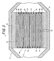
- the filters F1, F2 shown in FIGS. 2 and 3 have so-called honeycomb structures. Because, the honeycomb structure has a merit that the pressure loss is small even if the amount of fine particles caught increases.
- a great number of through-holes 12 having substantially a square form at section are regularly formed along a direction of an axial line.
- the through-holes 12 are partitioned with each other through thin cell walls 13.
- An opening part of each through-hole 12 is sealed at either end face 9a, 9b with a sealing body 14 (in this case, porous sintered silicon carbide). Therefore, the end faces 9a, 9b are opened in a checkered pattern as a whole. As a result, many cells having a square form at section are formed in the filters F1.
- the cell density is set to about 200 cells/inch
- the thickness of the cell wall 13 is set to about 0.3 mm
- the cell pitch is set to about 1.8 mm.
- upstream side end faces 9a are opened at about a half
- downstream side end faces 9b are opened at the remaining half.
- DPF is prepared by using the porous silicon carbide sintered body having communicated pores comprising the large pores and the small pores as a catalyst carrier and carrying a catalyst on a surface thereof.
- the various catalysts it is possible to carry the various catalysts not only on the outer surface of the cell wall but also in the inside of the cell wall or inner surface of the large pore, so that the occlusion reduction of NOx and combustion of PM are efficiently promoted at the surface and the inside of the cell wall.
- PM can be burnt so as not to leave unburnt portion even in the sintered body having a low thermal conductivity. Therefore, it is naturally preferable to use silicon carbide as a ceramic having a high thermal conductivity.
- a first adhesion layer 15 consisting essentially of an adhesion seal material using the following ceramic.
- a second adhesion layer 16 made of an adhesion sheet consisting essentially of the following ceramic is formed on an outer peripheral face 9c of a filter 9 consisting of the filters F1, F2 and a column-shaped diesel particulate aggregate for binding them.
- an inorganic fiber In the composition of the adhesive in the first adhesion layer 15 and the second adhesion layer 16 are contained an inorganic fiber, an inorganic binder, an organic binder and inorganic particles.
- the inorganic fiber is used at least one ceramic fiber selected from silica-alumina fiber, mullite fiber, alumina fiber and silica fiber or the like.
- the inorganic binder is used at least one colloidal sol selected from silica sol and alumina sol.
- the organic binder a hydrophilic organic polymer is preferable, and at least one polysaccharide selected from polyvinyl alcohol, methyl cellulose, ethyl cellulose and carboxymethyl cellulose is used.
- the inorganic particle is used at least one inorganic powder selected from silicon carbide, silicon nitride and boron nitride or an elastic material using whisker.
- the porous silicon carbide sintered body 20 in the embodiment of the invention has communicated pores comprising large pores 21 and small pores 22 arriving to the inside thereof. That is, the pores in the porous silicon carbide sintered body (large pores, small pores) are not independent individually but are communicated with each other.
- the communicated pores are comprised of the aforementioned two kinds of pores (i.e. large pore 21 and small pore 22) in which the small pores 22 are relatively small in the size as compared with the large pores 21 and are uniformly dispersed in the surface layer and the inside of the sintered body 20.
- the average pore size of the small pore 22 is preferable to be about 5 ⁇ m - 40 ⁇ m, more preferably about 15 ⁇ m - 35 ⁇ m. It is further preferable to be about 20 ⁇ m - 30 ⁇ m.
- the average pore size of the small pore is less than 5 ⁇ m, it is easy to prematurely clog the small pores 22 with a small amount of PM and there is a fear of increasing the pressure loss in a short time. While, when the average pore size of the small pore 22 exceeds 40 ⁇ m, PM easily passes through the communicated pores and hence the filtering efficiency lowers and there is a fear that it does not act as a structural body of the filter.
- the large pores 21 are relatively large in the size as compared with the small pores 22 and are dispersed in both the surface layer portion and the inside of the sintered body 20.
- the average pore size of the large pore 21 is preferable to be 1.5 times or more the average pore size of the small pore 22, more preferably 2.0 times - 10 times, and particularly about 2.0 times - 6.0 times.
- the average pore size of the large pore 21 is preferable to be 30 ⁇ m - 80 ⁇ m, more preferably 40 ⁇ m - 65 ⁇ m, most preferably 50 ⁇ m - 60 ⁇ m.
- the filtering area can not be sufficiently ensured and the clogging is prematurely and easily caused and the reduction of the pressure loss can not sufficiently be obtained.
- the average pore size of the large pore 21 exceeds 80 ⁇ m, the mechanical strength of the sintered body 20 is decreased by the increase of the porosity but also there is a fear that it is not established as a structural body for the filter.
- the value of the average pore size of the large pore 21 is set to be not more than 1/2 of the thickness of the cell wall 13.
- the ratio of the large pores in the porous silicon carbide sintered body 20 is about 5% - 15% as a volume ratio. More preferably, it is about 7% - 13%. When the ratio is less than 5%, the number of the large pores 21 is too small and it can not be attempted to increase the effective filtering area in the sintered body 20. While, when the ratio of the large pores occupied in the sintered body 20 exceeds 15%, the mechanical strength of the sintered body 20 lowers due to the increase of the porosity. Moreover, the occupying ratio of the large pores 21 can be calculated based on the total volume of a pore forming material 24 as mentioned later and the volume of the sintered body 20 (volume of substrate itself other than cells).
- the total volume of the pore forming material 24 can be calculated, for example, by dividing the addition amount of the pore forming material 24 by a density thereof, and the calculated value is approximately equal to the total volume of the large pores 21.
- a percentage of a value obtained by dividing the thus calculated total volume of the large pores 21 by the volume of the sintered body 20 corresponds to the occupying ratio of the large pores 21.
- the number of large pores 21 exposed or opened to the surface of the sintered body 20 per unit area is preferable to be 10 pores/mm 2 - 100 pores/mm 2 , more preferably 20 pores/mm 2 - 70 pores/mm 2 .
- the increase of the effective filtering area in the sintered body 20 can not sufficiently be obtained. While, when this number exceeds 100 pores/mm 2 , the mechanical strength of the sintered body 20 lowers due to the increase of the porosity but also there is a fear that the sintered body is not established as a structural body for filter.
- an optional region of 1 mm square is first set in a photograph of the sintered body surface pictured by means of a microscope and the number of large pores 21 existing in this region (exposed and opened to the sintered body surface) is counted. This procedure is carried out on plural regions and it is desired to calculate an average value.
- a ratio of silicon carbide in the porous silicon carbide sintered body 20 is preferable to be not less than 60% by weight, more preferably not less than 80% by weight, particularly not less than 95% by weight. As the silicon carbide ratio becomes higher, there is obtained porous sintered body surely possessing excellent mechanical strength, heat resistance, chemical stability and the like inherent to silicon carbide. On the other hand when the silicon carbide ratio is less than 60% by weight, the properties of the sintered body 20 lower and there is a fear that it is not suitable as a structural body for the filter.
- the content of impurity other than elemental silicon (Si) and elemental carbon (C) is less than 2%, particularly less than 1%.
- impurity means metals exemplified by iron (Fe), aluminum (Al), copper (Cu) and sodium (Na) and compounds thereof. The reason why elementary silicon and elementary carbon are not taken as the impurity is due to the fact that they are elements constituting silicon carbide and do not cause critical factor lowering the properties of the sintered body 20 even if they are contained in silicon carbide.
- the silicon carbide particle 23 constituting the porous silicon carbide sintered body 20 it is preferable to use particles having an average particle size of 5 ⁇ m - 30 ⁇ m, preferably about 8 ⁇ m - 15 ⁇ m.
- the average particle size of the silicon carbide particle is too small, the small pores 22 formed in the matrix portion of the sintered body become smaller and hence soot hardly passes through the communicated pores and the clogging easily occurs prematurely.
- the average particle size of the silicon carbide particle is too large, the small pores 22 formed in the matrix portion become large and soot easily passes through the communicated pores and hence the filtering efficiency lowers.
- the silicon carbide used in the invention it is preferable to use a mixed particle of one or more SiC particles consisting of small-size particles having an average particle size of about 0.5-5 ⁇ m and large-size particles having about 10-30 ⁇ m. By using such a mixed particle is made possible the formation of the small pores.
- silicon carbide particles 23 may be directly joined to each other by neck of silicon carbide itself (network structure) without silicon layer. Such a structure provides an excellent mechanical strength though the body is a porous body.
- a slurry of starting ceramic used in an extrusion shaping step a sealing paste used in a sealing step for an end face of a filter, a paste for the formation of a first layer used in a filter adhering step, a paste for the formation of a second layer used in an irregularity disappearing step, and the like.
- the sealing paste is used by compounding silicon carbide powder with an organic binder, a lubricant, a plasticizer and water and milling them.
- the paste for the formation of the first adhesion layer 15 is used by compounding given amounts of inorganic fibers, an inorganic binder, an organic binder, inorganic particles and water and then milling them.
- the paste for the formation of the second adhesion layer 16 is used by compounding given amounts of inorganic fibers, an inorganic binder, an organic binder, inorganic particles and water and then milling them.
- the inorganic particles can be omitted in the paste for the formation of the second adhesion layer 16 as mentioned above.
- the slurry of the starting ceramic is used by compounding the starting material consisting essentially of silicon carbide powder with given amounts of an organic binder, water and the like and then milling them to form a slurry.
- the pore forming material 24 is used a substance disappearing by heat at a stage before the arrival at a sintering temperature of silicon carbide (about 2200°C).
- the disappear by heat means that it is substantially disappeared from the sintered shaped body by sublimation, evaporation, decomposition, reaction sintering or the like through the heating in the sintering.
- the disappearing temperature is desirable to be lower, preferably not higher than 1000°C, more particularly not higher than 500°C. As the disappearing temperature becomes lower, the probability of leaving the impurity in the sintered body 20 becomes small, which can contribute to the increase of the silicon carbide ratio.
- the pore forming material 24 is desirable to be a kind not causing the foaming in the disappearance. In case of the pore forming material 24 causing the foaming, it is difficult to form large pores 21 having uniform shape and size, which fears an influence upon the quality of the sintered body 20.
- the pore forming material 24 there are particles made of synthetic resin and the like. Besides, particles of an organic polymer such as starch or the like, metal particles, ceramic particles and the like can be used. Preferably, spherical particles made of the synthetic resin are used as the pore forming material 24. Moreover, the particle form of the pore forming material is not limited to the spherical form, and may be an elongated spherical form, a cubic form, an amorphous lump form, columnar form, a plate form and the like. The pore forming material 24 is preferable to have an average particle size of 30 ⁇ m - 80 ⁇ m.
- the average particle size of the pore forming material 24 By setting the average particle size of the pore forming material 24 to the above preferable range can be surely produced the porous silicon carbide sintered body 20 having a small pressure loss and a high filtering efficiency. Further, the pore forming material is preferable to have the average particle size being not more than about 1/2 of a cell wall of the sintered body. Such an average particle size can prevent the formation of the communicated pores consisting of only the large pores.
- the pore forming material 24 is preferable to be compounded in the starting slurry in an amount of about 5% by weight to 25% by weight. Also, the concentration of impurities included in the pore forming material 24 (excludes elemental Si and elemental C) is preferable to be not more than 3% by weight, more preferably not more than 1% by weight. When the concentration of the impurity in the pore forming material 24 is low, the probability of leaving the impurity in the sintered body 20 becomes small, which contributes to the improvement of the silicon carbide ratio.
- the aforementioned ceramic starting slurry is charged into an extrusion shaping machine and continuously extruded through a mold.
- the shaping pressure is preferable to be set to 20 kgf/cm 2 - 60 kgf/cm 2 .
- the thus extrusion shaped honeycomb shaped body is cut into equal lengths to obtain cut pieces of a square pole honeycomb shaped body.
- a given amount of the sealing paste is filled in either side opened portions of cells of the cut piece in a checkered pattern to seal both end faces of the cut piece.
- the cut pieces of the honeycomb shaped body is dried and subjected to a degreasing treatment at a temperature of 300°C - 800°C, preferably 500°C - 600°C to remove the binder in the shaped body 19.
- a degreasing treatment step the pore forming material 24 of synthetic resin particles included in the shaped body disappears through heat and hence large pores 21 are formed in places existing the pore forming material 24 (see FIGS. 4(a), (b)).
- the thus formed large pores 21 fundamentally correspond to approximately the form and size of the pore forming material 24.
- filters F1 made of a square pole porous silicon carbide sintered body 20 (all of them are square pole at this time).
- the temperature of the firing is preferable to be 2150°C - 2300°C.
- the firing temperature is lower than 2150°C, the temperature is too low and the sintering reaction does not proceed and hence the improvement of the mechanical strength is hardly attained.
- the firing temperature is higher than 2300°C, the sintering excessively proceeds during the firing and there is a fear that the sintered body 20 is densified. As a result, suitable poring property can not be given to the porous silicon carbide sintered body 20.
- the firing time is set to 0.1 hour - 5 hours, and the furnace atmosphere in the firing is set to an inert atmosphere and an atmospheric pressure.
- the paste of the formation of the first adhesion layer is applied thereonto.
- 16 of such filters F1 are integrally united with each other by adhering the outer peripheral faces. At this time, the filter adhered structure as a whole is a square form at section.
- the filter adhered structure of the square form at section obtained through the filter adhering step is polished to remove unnecessary parts from the outer peripheral portion to thereby adjust the outer profile.
- an adhered structure of F1 and F2 having a disc form at section is obtained.
- cell walls 13 are partly exposed at the newly exposed face by the outer profile cutting and hence irregularity is developed on the outer peripheral face.
- This step is a step for removing the irregular face produced in the above outer profile cutting step, in which the paste for the formation of the second adhesion layer is uniformly applied onto the outer peripheral face of the filter adhered structure to form a second layer 16. As a result, a desired disc-shaped ceramic filter can be completed.
- the catalyst coat layer 28 is individually formed to each surface of the ceramic particles in the catalyst carrier made of the ceramic sintered body.
- the catalyst coat layer 28 is preferable to further contain an oxidation catalyst of a noble metal as an active component, titania, zirconia, as a co-catalyst, a NOx occulding catalyst of an alkali metal and/or an alkaline earth metal and the like. Then, each step (formation of catalyst coat layer, carrying of active component) is described when using alumina as a catalyst coat layer, cerium as a co-catalyst, platinum as an active component, potassium as a NOx occulding catalyst and the like.
- This step is a treatment for forming a rare earth oxide-containing alumina coat layer 28 on each surface of the ceramic particles by impregnating a solution of a metal compound containing aluminum and a rare earth element, e.g. a mixed aqueous solution of aluminum nitrate and cerium nitrate or the like in each surface of ceramic particles c constituting the cell wall of the ceramic filter 9 through sol-gel process (see FIG. 5).
- a metal compound containing aluminum and a rare earth element e.g. a mixed aqueous solution of aluminum nitrate and cerium nitrate or the like
- the aluminum-containing solution in the above mixed aqueous solution there are a metal inorganic compound and a metal organic compound as a starting metal compound.
- the metal inorganic compound are used Al(NO 3 ) 3 , AlCl 3 , AlOCl, AlPO 4 , Al 2 (SO 4 ) 3 , Al 2 O 3 , Al(OH) 3 , Al and the like.
- Al(NO 3 ) 3 or AlCl 3 is preferable because it is easily dissolved in a solvent such as alcohol, water or the like and is easy in the handling.
- the metal organic compound are mentioned a metal alkoxide, a metal acetylacetonate, a metal carboxylate and the like. Concretely, there are Al(OCH 3 ) 3 , Al(OC 2 )H 3 ) 3 , Al(iso-OC 3 H 7 ) 3 and the like.
- cerium-containing compound solution in the mixed aqueous solution there are used Ce(NO 3 ) 3 , CeCl 3 , Ce 2 (SO 4 ) 3 , Ce(OH) 3 , Ce 2 (CO 3 ) 3 and the like.
- a solvent for the mixed solution at least one of water, alcohol, diol, polyvalent alcohol, ethylene glycol, ethylene oxide, triethanolamine, xylene and the like considering the dissolution of the above metal compound.
- hydrochloric acid, sulfuric acid, nitric acid, acetic acid or hydrofluoric acid may be added as a catalyst in the preparation of the above solution.
- elementary K, Ca, Sr, Ba, La, Pr, Nd, Si, Zr or a compound thereof may be added to the starting material in addition to the rare earth oxide.
- Al(NO 3 ) 3 and Ce(NO 3 ) 3 may be mentioned as a preferable embodiment of the metal compound because they are dissolved in the solvent at a relatively low temperature and is easy in the preparation of the starting solution.
- 1,3-butane diol is recommended as a preferable solvent.
- a first reason of the recommendation is due to the fact that the viscosity is proper and a gel film having a proper thickness may be formed on SiC particle of a gel state.
- a second reason is that this solvent forms a metal alkoxide in the solution and is liable to easily form a metal oxide polymer having oxygen-metal-oxygen bond, i.e. a precursor of a metal oxide gel.
- the amount of Al(NO 3 ) 3 is desirable to be 10-50 mass%. When it is less than 10 mass%, there can not be carried an alumina amount having a surface area for maintaining the activity of the catalyst over a long time, while when it exceeds 50 mass%, the heat generation quantity becomes larger in the dissolution and the gelation is caused. Also, the amount of Ce(NO 3 ) 3 is preferable to be 1- 30 mass%. When the amount is less than 1 mass%, the oxidation can not be caused, while when it exceeds 30 mass%, the grain growth of CeO 2 occurs after the firing. On the other hand, the compounding ratio of Al(NO 3 ) 3 to Ce(NO 3 ) 3 is preferable to be about 10:2. Because, the dispersion degree of the CeO 2 particles after the firing can be improved by making rich Al(NO 3 ) 3 .
- the temperature is desirable to be 50-130°C.
- the stirring time is desirable to be 1-9 hours. Because, the stability of the solution is stable within this range.
- cerium-containing metal compounds of Al(NO 3 ) 3 and Ce(NO 3 ) 3 in order to produce a composite oxide or solid solution with zirconium in addition to the above example, it is preferable that Zr(NO 3 ) 2 or ZrO 2 is used as a zirconium source and dissolved in water or ethylene glycol to form a mixed solution, and they are impregnated into the mixed solution and dried and fired to obtain the composite oxide.
- the above adjusted solution of the metal compounds is inserted into all pores as a space between the ceramic (SiO) particles in the cell wall.
- a method wherein the catalyst carrier (filter) is placed in a vessel and filled with the above metal compound solution to conduct deaeration a method wherein the solution is flown into the filter from one end thereof and deaeration is carried out at the other end, and the like.
- a vacuum pump in addition to an aspirator may be used as an apparatus for deaeration.
- air in the pores of the cell wall can be removed off and hence the solution of the above metal compounds can be uniformly applied onto the surface of each ceramic particle.
- This step is a treatment in which volatile components such as NO 2 and the like are removed by evaporation and the solution is rendered into a gel to fix onto the ceramic particle surface and remove an extra solution.
- the heating is carried out at 120-170°C for about 2 hours. When the heating temperature is lower than 120°C, the volatile components hardly evaporate, while when it exceeds 170°C, the thickness of the gelated film becomes non-uniform.
- This step is a preliminary calcination treatment in which the residual components are removed to form an amorphous alumina film, and the heating at 300-1000°C for 5-20 hours is desirable.
- the calcination temperature is lower than 300°C, it is difficult to remove residual organic matters, while when it exceeds 1000°C, Al 2 O 3 is not amorphous but is crystallized and the surface area tends to lower.
- a rare earth oxide-containing alumina coat layer On the surface of the silicon carbide (SiC) ceramic carrier (filter) is formed a rare earth oxide-containing alumina coat layer, and platinum as an active component and potassium as a NOx occluding catalyst are carried on the surface of the alumina coat layer, respectively.
- a noble metal such as Pd, Ph or the like other than Pt may be included as the active component. These noble metals serve to generate NO 2 by reacting with NO and O 2 in the exhaust gas prior to the occlusion of NOx through the alkali metal or the alkaline earth metal, or to defuse NOx by reacting with combustible components in the exhaust gas when the NOx occluded is discharged.
- the kind of the alkali metal and/or alkaline earth metal included in the catalyst layer as NOx occluding component is not particularly limited.
- the alkali metal are mentioned Li, Na, K, Cs and as the alkaline earth metal are mentioned Ca, Ba, Sr and the like.
- the alkali metal having a high reactivity with Si, particularly K is used as the NOx occluding component among them, the invention is most effective.
- the amount of the active component carried is determined so that an aqueous solution containing Pt, K and the like is added dropwise and impregnated only by a water absorbing amount of the carrier to render into a slight wetted state of the surface.
- the water absorbing amount kept by the SiC ceramic carrier means that when the measured value on the water absorbing amount of the dried carrier is 22.46 mass%, if the carrier has a mass of 110 g and a volume of 0.163 l, the carrier absorbs 151.6 g/l of water.
- a starting substance of Pt for example, a solution of dinitrodiamine platinum nitrate ([Pt(NH 3 ) 2 (NO 2 ) 2 ]HNO 3 , Pt concentration: 4.53 mass%), while as a starting material of K is used, for example, an aqueous solution of potassium nitrate (KNO 3 ) mixed with the above platinum nitrate solution.
- the nitric acid solution (KNO 3 concentration: 99%) is diluted with distilled water so as to render KNO 3 into 0.0326 mol.
- the given amount of the thus adjusted aqueous solution of dinitrodiamine platinum nitrate is added dropwise onto both end faces of the carrier with a pipette at constant intervals.
- a pipette for example, 40-80 droplets are added to one-side face at constant intervals, whereby Pt is uniformly dispersed and fixed onto the surface of the alumina carried film covering the SiC ceramic carrier.
- the carrier is dried at 110°C for about 2 hours to remove water and transferred into a desiccator and left to stand for 1 hour to measure an adhesion amount by an electron scale or the like. Then, the firing is carried out in N 2 atmosphere under conditions of about 500°C-about 1 hour to fix Pt and K.
- an exhaust gas from a side of an upstream end face 9a.
- the exhaust gas fed through a first exhaust pipe 6 is first flown into cells having opened upstream end faces 9a and then passed through cell walls 13 to move over an inside of cells adjacent to the above cells or cells having opened downstream end faces 9b and thereafter flown out from the downstream end faces 9b of the filter F1 through the openings of these cells toward a second exhaust pipe 7.
- PM included in the exhaust gas can not pass through the cell walls 13 and traps therein.
- the purified exhaust gas is discharged from the downstream end faces of the filters F1, F2.
- the thus purified exhaust gas is further passed through the second exhaust pipe 7 and finally discharged into air.
- the ceramic heater 9 is heated by switching on a heater not shown to burn and remove PM.
- the ceramic filter 9 is reproduced and turned to a state capable of catching PM.
- the change is not fundamentally caused even if the use time becomes long.
- the PM layer 26 relating to the factor 4 becomes gradually thicker as the use time becomes long. Since PM is very fine particles, the resistance in the pass of the gas through the PM layer 26 is considerably large and hence the pressure loss becomes large as the deposited amount (caught amount) of PM becomes larger. That is, the reason why the pressure loss gradually increases can be said due to the fact that the thickness of the PM layer 26 increases. Therefore, it is effective to mitigate the increase of the pressure loss when the increase of the thickness of the PM layer 26 is prevented by any method.
- the DPF according to the invention is small in the pressure loss during the deposition of PM as compared with the DPF made of the sintered body simply existing only the small pores 22. Also, the DPF according to the invention is superior in the catching ability of soft cream to the DPF made of the sintered body existing only the large pores 21.
- the ceramic filter 9 according to the invention is preferably used in the application as a filter for the purification of exhaust gas in diesel engine (DPF), and particularly there is used DPF wherein the honeycomb is alternately clogged in a checkered pattern.
- This DPF itself has only a function that particulates (floating particle matter: PM) are caught by filtering walls (cell walls) as a catalyst carrier.
- a catalyst coat layer 28 is formed by carrying a catalyst active component on the cell wall of the DPF, particularly on surfaces of ceramic particles C as a constitutional component thereof, hydrocarbon and carbon monoxide in the exhaust gas can be oxidized.
- NOx selective reduction type catalyst component capable of reducing NOx or occlusion type catalyst component is carried on the surface of the ceramic filter 9 in an oxidizing atmosphere of the diesel exhaust gas, the reduction of NOx is possible.
- the PM caught in the DPF brings about the increase of the pressure loss in the DPF with the proceed of the deposition, it is usually required to reproduce it by combustion treatment or the like.
- a temperature starting the combustion of soot 26 (carbon) as a main component of PM usually included in the diesel exhaust gas is about 550-630°C.
- the catalyst coat layer 28 is formed on the ceramic filter 9 existing the large pores 21 and small pores (matrix) 22 in the surface layer portion and the inside of the catalyst carrier (cell walls), since the catalyst is uniformly coated on the surface of each of the ceramic particles C in the preferable embodiment of the invention, the opened pores are narrowed in both of the large pores 21 and small pores 22 (matrix). Since the wall wherein the large pores 21 exist is relatively thinned by the catalyst as compared with the surrounding portion thereof, the pressure loss relatively lowers. Therefore, the exhaust gas easily flows into the large pores 21. Also, when NOx in the exhaust gas passes through the surface of the greater amount of the catalyst coat carried, it is occluded by contacting with NOx occlusion catalyst.
- the PM layer 26, which is considered to be naturally deposited on the full surfaces of the catalyst carrier made of the ceramic sintered body as shown in FIG. 4(b) as mentioned above, is passed while contacting with the catalyst coat layer 28 on the inner faces of the large pores 21, whereby the contacting ratio of PM 27 with the catalyst coat layer 28 is increased.
- PM 27 easily passes through the large pores 21 and is stored thereon, but since a greater amount of the catalyst, co-catalyst and NOx occlusion catalyst are carried thereon, they play a function as a filter indicating a high catalyst active reaction.
- Such a filter is desirable to have a porosity of 50-80%.
- a ratio of forming closed cell by forming the large pores 21 and coating with the catalyst becomes large, while when it exceeds 80%, the gas flows through the whole of the filter walls irrespectively of the presence or absence of the large pores and it is considered that the above effect is not developed.
- A. function as a filter
- This example confirms the action and effect of pressure loss in the catching of soot with respect to a filter having large pores and small pores.
- 60% by weight of ⁇ -type silicon carbide powder made of two kinds of silicon carbide SiC powder A of 10 ⁇ m: 60 wt%, SiC powder B of 0.5 ⁇ m: 40 wt%) having an average particle size of 10 ⁇ m is milled with 10% by weight of an organic binder (methylcellulose) as a shaping assistant, 20% by weight of water as a dispersing solution and 10% by weight of spherical acryl resin (density: 1.1 g/cm3) as a pore forming material 24.
- an organic binder methylcellulose
- spherical acryl resin density: 1.1 g/cm3
- the above milled mass is further milled with 1 wt% of glycerin as a plasticizer and 3 wt% of uniloop as a lubricant, which is shaped by extrusion to obtain a honeycomb green shaped body 19.
- the green shaped body 19 is dried at 150°C and degreased at 500°C and fired under firing conditions shown in Table 1 to prepare a ceramic carrier made of a porous silicon carbide sintered body.
- FIG. 6 shows SEM photograph of the sintered body.
- FIG. 6(a) is a photograph of a cut surface of a cell wall portion in the sintered body 20
- FIG. 6(b) is an enlarged photograph of the section of the cell wall portion, from which is well seen a state of opening and exposing the large pores 21 to the surface.
- the occupying ratio of the large pores 21 is about 10% as a volume ratio and the number of the large pores 21 exposed and opened to the surface of the sintered body is about 40 pores/mm 2 .
- the silicon carbide ratio in the sintered body 20 is about 97% by weight and the silicon carbide particles 23 are directly joined to each other through necks without silicon layer.
- the content of the impurity in the sintered body 20 is less than 7000 ppm.
- a honeycomb green shaped body 19 is obtained fundamentally using the same shaping material as in the example and shaping it through extrusion.
- the pore forming material 24 is not added to the shaping material.
- the green shaped body 19 is subjected to degreasing and firing under the same conditions as in the example.
- a porous silicon carbide sintered body 20 in which an average particle size of the silicon carbide particles 23 is 10 ⁇ m and an average pore size is 9 ⁇ m. That is, there is obtained the sintered body 20 having only small pores 22 in its matrix.
- a honeycomb green shaped body 19 is obtained fundamentally using the same shaping material as in the example and shaping it through extrusion.
- the pore forming material 24 is not added to the shaping material and a large particle size ⁇ -type silicon carbide powder having an average particle size of silicon carbide powder having an average particle size of 30 ⁇ m is used.
- the shaped body 19 is subjected to degreasing and firing under the same conditions as in the example.
- a porous silicon carbide sintered body 20 in which an average particle size of the silicon carbide particles 23 is 30 ⁇ m and an average pore size is 30 ⁇ m. That is, there is obtained the sintered body 20 having only large pores 21.
- Table 1 With respect to the sintered bodies are made various tests to obtain results shown in Table 1.
- a ceramic filter 9 having a diameter of 140 mm and a length of 50 mm is prepared by integrally uniting a plurality of the example sintered bodies 20 (i.e. filters F1). Similarly, ceramic filters 9 are prepared with respect to Comparative Example 1 and Test Example 1.
- each of the thus obtained three ceramic filters 9 is used to assemble an exhaust gas purifying apparatus 1, which is attached to an exhaust path of a continuous operation of the engine is carried out by setting the revolution number to 3500 rpm under no load, during which the change of pressure loss is measured with the lapse of time to obtain the results as shown in FIG. 7.
- an abscissa is a time (minutes) and an ordinate is a quantity of pressure loss (kPa).
- the pressure is measured at upstream side end and downstream side end of the casing 8, respectively, and the difference therebetween is "value of pressure loss".
- the value of pressure loss at initial catching time of soot is about 1.6 kPa in Comparative Example 1.
- the pressure loss value increases with the lapse of time, and particularly the pressure loss value rapidly rises after 10-20 minutes. This is due to the fact that a greater amount of the pores are clogged with the soot invaded into the cell walls 13.
- the pressure loss value arrives at about 11.3 kPa, which is a very high value as compared with the other test members.
- the value of pressure loss at initial catching time of soot is about 1.6 kPa. Thereafter, the pressure loss value increases with the lapse of time, and particularly the pressure loss value rapidly rises after 15-25 minutes. This is due to the fact that a greater amount of the pores are clogged with the soot invaded into the cell walls 13. At the time after 100 minutes, the pressure loss value finally arrives at about 9 kPa, which is a very high value as compared with the other test member.
- the pressure loss value at initial catching time of PM is about 2 kPa in Example 1 suitable for the invention. Thereafter, the pressure loss value gradually increases with the lapse of time, but it is about 7 kPa at the time after 100 minutes. Moreover, the soot leakage is not observed in this example.
- This example is carried out for confirming the action-effects when an alumina coat layer is formed on the surface of the filter having a changed porosity as a catalyst coat layer and NOx occlusion reduction catalyst carried thereon.
- a columnar DPF consisting of the thus obtained ceramic filter aggregate is attached to an exhaust gas purifying apparatus of a diesel engine having a displacement of 2.0 liters. Then, the continuous operation of the engine is carried out by setting the revolution number to 3500 rpm under no load, during which a purification ratio of NOx is measured to obtain results as shown in FIG. 8.
- the NOx purification ratio tends to become higher in the mixed system of large pores and small pores (matrix) than in the system of only small pores (matrix). Also, as the porosity becomes smaller than 50%, even if the large pores are existent, the NOx purification ratio becomes not too high. On the other hand, even when the porosity becomes higher than 80%, even if the large pores are existent, the NOx purification ratio is not raised.
- the ceramic filter aggregate suitable for the invention has communicated pores consisting of large pores existing in the surface layer portion and inside of the sintered body and small pores existing in the surface layer and inside of the sintered body and the catalyst coat layer is formed thereon, the pressure loss is low, and PM and the exhaust gas concentratedly flows into the large pores, so that NOx occlusion effect easily occurs in both places of the surface layer portion and inside of the ceramic carrier existing PM and the effective NOx purification ratio can be obtained.
- graphite and carbon as a pore forming material are milled with the same shaping assistant and dispersion medium as in Example 1 to 100 parts of ceramic starting material consisting of 40 parts by weight of talc, 10 parts by weight of kaoline, 17 parts by weight of alumina, 16 parts by weight of aluminum hydroxide and 17 parts by weight of silica.
- the thus milled mass is shaped through extrusion in the same manner as in Example 1, which is cut, dried and fired at 1400°C for 3 hours to obtain a honeycomb structural body of cordierite. Then, the structural body is clogged in a checkered pattern by using the same sealing material as in Example 1 and fired in the sane manner as in Example 1 to obtain a filter for the purification of the exhaust gas having the same shape as in Example 1.
- Example 3 the same filter as in Example 3 is prepared in the comparative examples except that the pore forming material is not added.
- the compounding materials in the ceramic sintered body, firing conditions and pore size are shown in Table 3.
- the porous ceramic sintered body suitable of the production of DPF being small in the pressure loss during the deposition of soot and having a high filtering efficiency.
- the DPF being small in the pressure loss during the deposition of soot and having a high filtering efficiency, which can be rendered into DPF being high in the NOx purification efficiency and short in the rich spike time.
- the invention is applicable as an exhaust gas purifying apparatus attached to a diesel engine, other exhaust gas purifying apparatuses, a filtering filter for high-temperature fluid or high-temperature steam, a filter for a plating liquid or a filter used for a thermal exchanging member.
Landscapes
- Chemical & Material Sciences (AREA)
- Engineering & Computer Science (AREA)
- Chemical Kinetics & Catalysis (AREA)
- Combustion & Propulsion (AREA)
- Materials Engineering (AREA)
- Mechanical Engineering (AREA)
- General Engineering & Computer Science (AREA)
- Organic Chemistry (AREA)
- Ceramic Engineering (AREA)
- Geometry (AREA)
- Physics & Mathematics (AREA)
- Structural Engineering (AREA)
- Health & Medical Sciences (AREA)
- Biomedical Technology (AREA)
- Environmental & Geological Engineering (AREA)
- Analytical Chemistry (AREA)
- General Chemical & Material Sciences (AREA)
- Oil, Petroleum & Natural Gas (AREA)
- Filtering Materials (AREA)
Applications Claiming Priority (3)
| Application Number | Priority Date | Filing Date | Title |
|---|---|---|---|
| JP2001165548 | 2001-05-31 | ||
| JP2001165548 | 2001-05-31 | ||
| PCT/JP2002/005396 WO2002096827A1 (fr) | 2001-05-31 | 2002-05-31 | Corps fritte ceramique poreux et procede permettant sa production, et filtre a gasoil particulaire |
Related Child Applications (1)
| Application Number | Title | Priority Date | Filing Date |
|---|---|---|---|
| EP06018440.5 Division-Into | 2006-09-04 |
Publications (3)
| Publication Number | Publication Date |
|---|---|
| EP1403231A1 true EP1403231A1 (fr) | 2004-03-31 |
| EP1403231A4 EP1403231A4 (fr) | 2005-04-13 |
| EP1403231B1 EP1403231B1 (fr) | 2012-11-21 |
Family
ID=19008202
Family Applications (1)
| Application Number | Title | Priority Date | Filing Date |
|---|---|---|---|
| EP02728214A Expired - Lifetime EP1403231B1 (fr) | 2001-05-31 | 2002-05-31 | Procede de production d'un corps ceramique fritté poreux |
Country Status (4)
| Country | Link |
|---|---|
| US (1) | US20040161596A1 (fr) |
| EP (1) | EP1403231B1 (fr) |
| JP (1) | JPWO2002096827A1 (fr) |
| WO (1) | WO2002096827A1 (fr) |
Cited By (18)
| Publication number | Priority date | Publication date | Assignee | Title |
|---|---|---|---|---|
| WO2005044422A1 (fr) | 2003-11-07 | 2005-05-19 | Ibiden Co., Ltd. | Corps a structure en nid d'abeille |
| WO2006044268A1 (fr) * | 2004-10-13 | 2006-04-27 | Dow Global Technologies Inc. | Filtre a suie de diesel catalyse et son procede d’utilisation |
| WO2007012777A2 (fr) * | 2005-07-29 | 2007-02-01 | Saint-Gobain Centre De Recherches Et D'etudes Europeen | Procede de preparation d'une structure poreuse utilisant des agents porogenes a base de silice |
| EP1769838A2 (fr) * | 2005-09-28 | 2007-04-04 | Ibiden Co., Ltd. | Filtre en nid d'abeilles |
| EP1795262A1 (fr) * | 2004-09-30 | 2007-06-13 | Ibiden Co., Ltd. | Structure alvéolaire |
| EP1818098A1 (fr) * | 2004-11-26 | 2007-08-15 | Ibiden Co., Ltd. | Structure en nid d'abeille |
| WO2008078046A2 (fr) | 2006-12-21 | 2008-07-03 | Saint-Gobain Centre De Recherches Et D'etudes Europeen | Procede d'obtention d'une structure poreuse a base de carbure de silicium |
| WO2010007324A1 (fr) * | 2008-07-17 | 2010-01-21 | Saint-Gobain Centre De Recherches Et D'etudes Europeen | Filtre a particules texture pour applications catalytiques |
| EP2151271A1 (fr) * | 2008-08-05 | 2010-02-10 | Mann+Hummel Gmbh | Procédé de fabrication d'un élément de filtre céramique |
| US7851396B2 (en) | 2006-03-31 | 2010-12-14 | Ibiden Co., Ltd. | Porous sintered body, method of manufacturing porous sintered body, and method of manufacturing exhaust gas purifying apparatus |
| WO2012080620A1 (fr) | 2010-12-15 | 2012-06-21 | Saint-Gobain Isover | Procede pour preparer un materiau isolant |
| DE112010001885T5 (de) | 2009-04-02 | 2012-09-13 | SAINT-GOBAIN CENTRE DE RECHERCHES ET D'ETUDES EUROPéEN | SiC Filterstruktur mit verbesserten thermomechanischen Eigenschaften |
| EP2572771A1 (fr) * | 2011-09-06 | 2013-03-27 | NGK Insulators, Ltd. | Structure en nid dýabeille et corps catalytique en nid dýabeille |
| EP2727640A1 (fr) | 2012-11-06 | 2014-05-07 | Fraunhofer-Gesellschaft zur Förderung der angewandten Forschung e.V. | Filtre à particules |
| WO2016155971A1 (fr) * | 2015-04-01 | 2016-10-06 | Reishauer Ag | Outils de ponçage à pores ouverts, à liant céramique, procédé de fabrication desdits outils de ponçage et mélanges d'agents porogènes utilisés pour ladite fabrication |
| CH713958A1 (de) * | 2017-07-07 | 2019-01-15 | Exentis Tech Ag | System bestehend aus einem Träger mit Strömungskanälen und mindestens einer katalystisch wirksamen Substanz. |
| EP3919153A4 (fr) * | 2019-03-29 | 2022-03-30 | Denso Corporation | Filtre de purification de gaz d'échappement |
| EP3919155A4 (fr) * | 2019-05-15 | 2022-04-13 | Denso Corporation | Filtre d'épuration de gaz d'échappement |
Families Citing this family (129)
| Publication number | Priority date | Publication date | Assignee | Title |
|---|---|---|---|---|
| EP1688171B2 (fr) * | 1999-09-29 | 2013-03-27 | Ibiden Co., Ltd. | Filtre en nid d'abeilles et ensemble de filtres ceramiques |
| WO2003067042A1 (fr) | 2002-02-05 | 2003-08-14 | Ibiden Co., Ltd. | Filtre a nids d'abeille pour la decontamination des gaz d'echappement |
| CN100427730C (zh) * | 2002-02-05 | 2008-10-22 | 揖斐电株式会社 | 废气净化用蜂巢式过滤器、接合剂、涂布材料以及废气净化用蜂巢式过滤器的制造方法 |
| DE60317942T2 (de) | 2002-03-15 | 2008-11-27 | Ibiden Co., Ltd., Ogaki | Keramikfilter zur Abgasreinigung |
| DE60317174T3 (de) * | 2002-03-22 | 2013-01-17 | Ibiden Co., Ltd. | Herstellungsverfahren eines wabenfilters zur reinigung von abgas |
| WO2003082467A1 (fr) * | 2002-03-28 | 2003-10-09 | Ngk Insulators, Ltd. | Corps structurel cellulaire, procede de fabrication d'un corps structurel cellulaire et corps structurel de catalyseur |
| WO2003086579A1 (fr) * | 2002-03-29 | 2003-10-23 | Ibiden Co., Ltd. | Filtre en ceramique et unite de decontamination de gaz d'echappement |
| CN100371562C (zh) * | 2002-04-10 | 2008-02-27 | 揖斐电株式会社 | 废气净化用蜂窝状过滤器 |
| US20030194363A1 (en) * | 2002-04-12 | 2003-10-16 | Koripella Chowdary Ramesh | Chemical reactor and fuel processor utilizing ceramic technology |
| JPWO2004024294A1 (ja) * | 2002-09-13 | 2006-01-05 | イビデン株式会社 | フィルタ |
| JP4437084B2 (ja) * | 2002-10-07 | 2010-03-24 | イビデン株式会社 | ハニカム構造体 |
| JP4567285B2 (ja) * | 2002-11-22 | 2010-10-20 | 日本碍子株式会社 | 排ガス浄化用触媒体 |
| ATE481151T1 (de) * | 2003-02-28 | 2010-10-15 | Ibiden Co Ltd | Keramische wabenstruktur |
| PL1541817T3 (pl) * | 2003-06-05 | 2007-05-31 | Ibiden Co Ltd | Korpus o strukturze plastra miodu |
| EP1736225A3 (fr) * | 2003-06-10 | 2007-01-17 | Ibiden Co., Ltd. | Corps de structure en nid d abeille |
| DE602004006204T2 (de) * | 2003-06-23 | 2008-01-10 | Ibiden Co., Ltd., Ogaki | Wabenstrukturkörper |
| EP1538133B1 (fr) * | 2003-06-23 | 2018-01-10 | Ibiden Co., Ltd. | Structure en nid d'abeilles |
| DE602004005107T2 (de) * | 2003-07-02 | 2007-06-28 | Haldor Topsoe A/S | Verfahren und Filter zur katalytischen Behandlung von Dieselabgasen |
| US7455709B2 (en) * | 2003-07-15 | 2008-11-25 | Ibiden Co., Ltd. | Honeycomb structural body |
| EP1686107A4 (fr) * | 2003-09-12 | 2008-12-03 | Ibiden Co Ltd | Comprime en ceramique frittee et filtre en ceramique |
| PL1676620T5 (pl) * | 2003-10-20 | 2012-10-31 | Ibiden Co Ltd | Struktura plastra miodu |
| JP4439236B2 (ja) * | 2003-10-23 | 2010-03-24 | イビデン株式会社 | ハニカム構造体 |
| US7981475B2 (en) * | 2003-11-05 | 2011-07-19 | Ibiden Co., Ltd. | Manufacturing method of honeycomb structural body, and sealing material |
| JPWO2005064128A1 (ja) * | 2003-12-25 | 2007-07-19 | イビデン株式会社 | 排気ガス浄化装置および排気ガス浄化装置の再生方法 |
| US7387829B2 (en) * | 2004-01-13 | 2008-06-17 | Ibiden Co., Ltd. | Honeycomb structure, porous body, pore forming material for the porous body, and methods for manufacturing the pore forming material, the porous body and the honeycomb structure |
| EP1726795A4 (fr) * | 2004-02-23 | 2008-03-05 | Ibiden Co Ltd | Corps structurel en nid d'abeilles et appareil d'epuration de gaz d'echappement |
| KR100637298B1 (ko) * | 2004-04-05 | 2006-10-24 | 이비덴 가부시키가이샤 | 벌집형 구조체, 벌집형 구조체의 제조 방법 및 배기 가스정화 장치 |
| JPWO2005108328A1 (ja) * | 2004-05-06 | 2008-03-21 | イビデン株式会社 | ハニカム構造体及びその製造方法 |
| CN101249350B (zh) * | 2004-05-18 | 2012-02-22 | 揖斐电株式会社 | 蜂窝结构体及废气净化装置 |
| WO2006013651A1 (fr) | 2004-08-04 | 2006-02-09 | Ibiden Co., Ltd. | Four à calciner et processus pour produire un membre de thermomousse dans celui-ci |
| KR100842595B1 (ko) * | 2004-08-04 | 2008-07-01 | 이비덴 가부시키가이샤 | 연속 소성로 및 이것을 이용한 다공질 세라믹 부재의 제조방법 |
| CN1973171B (zh) | 2004-08-10 | 2010-05-05 | 揖斐电株式会社 | 烧制炉及利用该烧制炉制造陶瓷部件的方法 |
| US20060043027A1 (en) * | 2004-09-01 | 2006-03-02 | Nguyen Ledu Q | Automotive fluid filter with sintered pellet filter medium and associated method |
| JP4954705B2 (ja) * | 2004-09-14 | 2012-06-20 | 日本碍子株式会社 | 多孔質ハニカムフィルター |
| JPWO2006035823A1 (ja) * | 2004-09-30 | 2008-05-15 | イビデン株式会社 | ハニカム構造体 |
| DE602005015610D1 (de) * | 2004-10-12 | 2009-09-03 | Ibiden Co Ltd | Keramische wabenstruktur |
| JP4880581B2 (ja) * | 2005-02-04 | 2012-02-22 | イビデン株式会社 | セラミックハニカム構造体 |
| WO2006082938A1 (fr) * | 2005-02-04 | 2006-08-10 | Ibiden Co., Ltd. | Structure en nid d’abeille ceramique et procede de fabrication de celle-ci |
| US20060179825A1 (en) * | 2005-02-16 | 2006-08-17 | Eaton Corporation | Integrated NOx and PM reduction devices for the treatment of emissions from internal combustion engines |
| JP4870559B2 (ja) | 2005-03-28 | 2012-02-08 | イビデン株式会社 | ハニカム構造体 |
| JPWO2006112052A1 (ja) * | 2005-03-30 | 2008-11-27 | イビデン株式会社 | 炭化珪素含有粒子、炭化珪素質焼結体を製造する方法、炭化珪素質焼結体、及びフィルター |
| JP4937116B2 (ja) * | 2005-04-28 | 2012-05-23 | イビデン株式会社 | ハニカム構造体 |
| EP1752390B1 (fr) * | 2005-06-06 | 2011-09-28 | Ibiden Co., Ltd. | Utilisation d'un materiau d'emballage et procede de transport d'une structure en nid d'abeilles |
| JP2007021368A (ja) * | 2005-07-15 | 2007-02-01 | Toyota Motor Corp | 触媒担持用多孔質基材及び排気浄化装置 |
| WO2007015550A1 (fr) * | 2005-08-03 | 2007-02-08 | Ibiden Co., Ltd. | Gabarit pour la cuisson de carbure de silicium et procédé de production d’un corps poreux de carbure de silicium |
| KR100884518B1 (ko) * | 2005-08-26 | 2009-02-18 | 이비덴 가부시키가이샤 | 허니컴 구조체 및 그 제조 방법 |
| JPWO2007039991A1 (ja) * | 2005-10-05 | 2009-04-16 | イビデン株式会社 | 押出成形用金型及び多孔質セラミック部材の製造方法 |
| JPWO2007043245A1 (ja) * | 2005-10-12 | 2009-04-16 | イビデン株式会社 | ハニカムユニット及びハニカム構造体 |
| JP4839773B2 (ja) * | 2005-10-21 | 2011-12-21 | トヨタ自動車株式会社 | Pm浄化装置の製造方法 |
| KR100882401B1 (ko) * | 2005-11-18 | 2009-02-05 | 이비덴 가부시키가이샤 | 벌집형 구조체 |
| WO2007074508A1 (fr) * | 2005-12-26 | 2007-07-05 | Ibiden Co., Ltd. | Procédé de fabrication d’un corps de structure alvéolaire |
| WO2007074528A1 (fr) * | 2005-12-27 | 2007-07-05 | Ibiden Co., Ltd. | Gabarit de dégraissage, procédé de dégraissage de céramique moulée, et processus de fabrication de structure alvéolaire |
| CN101309883B (zh) * | 2006-01-27 | 2012-12-26 | 揖斐电株式会社 | 蜂窝结构体及其制造方法 |
| WO2007086143A1 (fr) * | 2006-01-30 | 2007-08-02 | Ibiden Co., Ltd. | Procede d'inspection d'un corps de structure en nid d'abeilles et procede de production d'un corps de structure en nid d'abeilles |
| EP1985365A1 (fr) * | 2006-02-14 | 2008-10-29 | Ngk Insulators, Ltd. | Structure en nid d'abeille et corps de catalyseur en nid d'abeille |
| WO2007094075A1 (fr) * | 2006-02-17 | 2007-08-23 | Ibiden Co., Ltd. | Unité d'assemblage et unité de desassemblage de dispositif de fixation pour le séchage, appareil de circulation dudit dispositif, procédé de séchage de moulage en céramique, et procédé de production de structure en nid d'abeille |
| WO2007097056A1 (fr) * | 2006-02-23 | 2007-08-30 | Ibiden Co., Ltd. | Structure en nid d'abeille et purificateur de gaz de rejet |
| WO2007097000A1 (fr) * | 2006-02-24 | 2007-08-30 | Ibiden Co., Ltd. | Dispositif de scellage des extremites pour corps en nid d'abeille, procede d'application de materiau de scellement en pate et procede de production d'un corps a structure en nid d'abeille |
| WO2007097004A1 (fr) * | 2006-02-24 | 2007-08-30 | Ibiden Co., Ltd. | Appareil et procede de melangeage a l'etat humide et procede de production de structures en nid d'abeille |
| DE602006002244D1 (de) * | 2006-02-28 | 2008-09-25 | Ibiden Co Ltd | Trageelement für Trocknung, Trocknungsverfahren eines Presslings mit Wabenstruktur, und Verfahren zur Herstellung eines Wabenkörpers. |
| WO2007102217A1 (fr) * | 2006-03-08 | 2007-09-13 | Ibiden Co., Ltd. | refroidisseur de corps cuit, four de cuisson, procédé de refroidissement de corps cuit céramique, et processus de fabrication de structure alvéolaire |
| WO2007102216A1 (fr) * | 2006-03-08 | 2007-09-13 | Ibiden Co., Ltd. | appareil pour introduction dans un four à dégraissage et processus de fabrication de structure alvéolaire |
| WO2007108076A1 (fr) * | 2006-03-17 | 2007-09-27 | Ibiden Co., Ltd. | Appareil de séchage, méthode de séchage d'une piece moulée céramique, et méthode de production d'une structure en nid d'abeille |
| WO2007116529A1 (fr) * | 2006-04-11 | 2007-10-18 | Ibiden Co., Ltd. | appareil de découpe d'un article moulé, procédé de découpe d'un article moulé en céramique et processus pour produire une structure en nid d'abeille |
| WO2007122680A1 (fr) * | 2006-04-13 | 2007-11-01 | Ibiden Co., Ltd. | Machine de moulage par extrusion, procédé de moulage par extrusion et procédé destiné à produire une structure en nid d'abeille |
| WO2007122707A1 (fr) * | 2006-04-19 | 2007-11-01 | Ibiden Co., Ltd. | Procédé permettant de produire une structure en nid d'abeille |
| WO2007122715A1 (fr) * | 2006-04-20 | 2007-11-01 | Ibiden Co., Ltd. | Méthode d'inspection d'un corps cuit en nid d'abeilles et procédé de fabrication d'une structure en nid d'abeilles |
| WO2007122716A1 (fr) * | 2006-04-20 | 2007-11-01 | Ibiden Co., Ltd. | Dispositif de transport et procédé de fabrication d'une structure en nid d'abeilles |
| WO2007129391A1 (fr) * | 2006-05-01 | 2007-11-15 | Ibiden Co., Ltd. | Unité de montage de gabarit de cuisson, unité de démontage de gabarit de cuisson, appareil de circulation, procédé de moulage de céramique de cuisson, et processus de production de structure de nid d'abeille |
| WO2007129399A1 (fr) * | 2006-05-08 | 2007-11-15 | Ibiden Co., Ltd. | PROCÉDÉ DE FABRICATION D'UNE STRUCTURE EN NID D'ABEILLES, MACHINE DE RÉCePTION DE MOULAGES EN NID D'ABEILLES ET MACHINE DE DÉMONTAGE DE MOULAGES EN NID D'ABEILLES |
| WO2007132530A1 (fr) * | 2006-05-17 | 2007-11-22 | Ibiden Co., Ltd. | Appareil de finition de face d'extrémité pour moulage alvéolaire, procédé d'obturation de moulage alvéolaire et processus de fabrication de structure alvéolaire |
| WO2007138701A1 (fr) * | 2006-05-31 | 2007-12-06 | Ibiden Co., Ltd. | Dispositif de maintien et procédé de production de structure alvéolaire |
| EP1880818A1 (fr) * | 2006-06-05 | 2008-01-23 | Ibiden Co., Ltd. | Méthode pour la coupe d'une structure en nid d'abeilles |
| ATE425852T1 (de) * | 2006-07-07 | 2009-04-15 | Ibiden Co Ltd | Apparat und verfahren zur bearbeitung der endflache eines wabenkírpers und verfahren zur herstellung eines wabenkírpers |
| WO2008032391A1 (fr) * | 2006-09-14 | 2008-03-20 | Ibiden Co., Ltd. | Procédé de production d'une structure en nid d'abeille et composition de matière première pour nid d'abeille calciné |
| DE602006014830D1 (de) * | 2006-09-14 | 2010-07-22 | Ibiden Co Ltd | Verfahren zur Herstellung eines Wabenkörpers und Zusammensetzung für Sinterwabenkörper |
| WO2008032390A1 (fr) * | 2006-09-14 | 2008-03-20 | Ibiden Co., Ltd. | Procédé de production d'une structure en nid d'abeille |
| WO2008047404A1 (fr) * | 2006-10-16 | 2008-04-24 | Ibiden Co., Ltd. | Support de montage pour structure alvéolaire et dispositif d'inspection pour structure alvéolaire |
| EP1941940A1 (fr) * | 2007-01-03 | 2008-07-09 | Ford Global Technologies, LLC | Substrat poreux à utiliser en tant que filtre à particules pour des procédés de régénération catalytique ou non catalytique de la suie |
| JP5076192B2 (ja) | 2007-01-12 | 2012-11-21 | 国立大学法人 岡山大学 | 未燃カーボンを用いてディーゼルエンジン排ガス中の窒素酸化物を浄化するための触媒と方法 |
| WO2008090625A1 (fr) * | 2007-01-26 | 2008-07-31 | Ibiden Co., Ltd. | Appareil pour former une couche périphérique externe et procédé de fabrication d'une structure en nid d'abeilles |
| WO2008105081A1 (fr) * | 2007-02-28 | 2008-09-04 | Ibiden Co., Ltd. | Filtre en nid d'abeilles |
| WO2008105082A1 (fr) * | 2007-02-28 | 2008-09-04 | Ibiden Co., Ltd. | Structure en nid d'abeilles |
| WO2008120291A1 (fr) * | 2007-02-28 | 2008-10-09 | Ibiden Co., Ltd. | Procédé de fabrication d'une structure de nid d'abeilles |
| WO2008126334A1 (fr) * | 2007-03-30 | 2008-10-23 | Ibiden Co., Ltd. | Procédé de production d'une structure en nid d'abeilles |
| WO2008126331A1 (fr) * | 2007-03-30 | 2008-10-23 | Ibiden Co., Ltd. | Filtre en nid d'abeilles |
| KR101025465B1 (ko) * | 2007-03-30 | 2011-04-04 | 이비덴 가부시키가이샤 | 허니컴 구조체 및 허니컴 구조체의 제조 방법 |
| WO2008126320A1 (fr) * | 2007-03-30 | 2008-10-23 | Ibiden Co., Ltd. | Procédé de fabrication d'une structure en nid d'abeilles |
| WO2008126332A1 (fr) | 2007-03-30 | 2008-10-23 | Ibiden Co., Ltd. | Filtre en nid d'abeilles |
| WO2008126330A1 (fr) * | 2007-03-30 | 2008-10-23 | Ibiden Co., Ltd. | Structure en nid d'abeilles |
| WO2008126333A1 (fr) * | 2007-03-30 | 2008-10-23 | Ibiden Co., Ltd. | Structure en nid d'abeilles |
| WO2008126321A1 (fr) * | 2007-03-30 | 2008-10-23 | Ibiden Co., Ltd. | Système de purification des gaz d'échappement |
| WO2008136078A1 (fr) * | 2007-04-20 | 2008-11-13 | Ibiden Co., Ltd. | Filtre en nid d'abeilles |
| WO2008139581A1 (fr) * | 2007-05-09 | 2008-11-20 | Ibiden Co., Ltd. | Procédé de production d'une matière première pour la cuisson de carbure de silicium et procédé de production d'une structure en nid d'abeille |
| WO2008139608A1 (fr) * | 2007-05-14 | 2008-11-20 | Ibiden Co., Ltd. | Structure en nid d'abeille et procédé de production de la structure en nid d'abeille |
| WO2008149435A1 (fr) * | 2007-06-06 | 2008-12-11 | Ibiden Co., Ltd. | Gabarit de cuisson et procédé de fabrication d'une structure en nid d'abeilles |
| WO2008155856A1 (fr) * | 2007-06-21 | 2008-12-24 | Ibiden Co., Ltd. | Structure en nid d'abeille et son procédé de production |
| US20080318071A1 (en) * | 2007-06-21 | 2008-12-25 | Moen Incorporated | Metallic coating on substrate |
| FR2921848B1 (fr) * | 2007-10-08 | 2011-03-18 | Saint Gobain Ct Recherches | Structure de purification texturee incorporant un systeme de catalyse electrochimique |
| JP5180835B2 (ja) * | 2007-10-31 | 2013-04-10 | イビデン株式会社 | ハニカム構造体用梱包体、及び、ハニカム構造体の輸送方法 |
| WO2009066388A1 (fr) * | 2007-11-21 | 2009-05-28 | Ibiden Co., Ltd. | Structure en nid-d'abeilles et son procédé de production |
| WO2009101682A1 (fr) * | 2008-02-13 | 2009-08-20 | Ibiden Co., Ltd. | Structure en nid d'abeilles, appareil de purification de gaz d'échappement et processus de production d'une structure en nid d'abeilles |
| WO2009101683A1 (fr) | 2008-02-13 | 2009-08-20 | Ibiden Co., Ltd. | Processus de production d'une structure en nid d'abeilles |
| JPWO2009107230A1 (ja) * | 2008-02-29 | 2011-06-30 | イビデン株式会社 | ハニカム構造体用シール材、ハニカム構造体、及び、ハニカム構造体の製造方法 |
| WO2009118814A1 (fr) * | 2008-03-24 | 2009-10-01 | イビデン株式会社 | Filtre en nid d'abeilles |
| WO2009118816A1 (fr) * | 2008-03-24 | 2009-10-01 | イビデン株式会社 | Structure en nid d'abeille |
| WO2009118813A1 (fr) * | 2008-03-24 | 2009-10-01 | イビデン株式会社 | Structure en nid d'abeille et son procédé de production |
| WO2009118862A1 (fr) * | 2008-03-27 | 2009-10-01 | イビデン株式会社 | Procédé de production d'une structure en nid d'abeilles |
| JP4980299B2 (ja) * | 2008-06-09 | 2012-07-18 | 東京窯業株式会社 | 炭化ケイ素質多孔体 |
| JP2010194430A (ja) | 2009-02-24 | 2010-09-09 | Toyota Central R&D Labs Inc | 触媒付パティキュレートフィルタ |
| EP2548626A4 (fr) * | 2010-03-19 | 2015-04-22 | Sumitomo Chemical Co | Procédé de fabrication d'une structure en nid d'abeilles, structure en nid d'abeilles et filtre à particules |
| WO2011132297A1 (fr) | 2010-04-22 | 2011-10-27 | イビデン株式会社 | Structure alvéolaire |
| WO2011132298A1 (fr) | 2010-04-22 | 2011-10-27 | イビデン株式会社 | Structure alvéolaire |
| KR101159756B1 (ko) * | 2010-05-18 | 2012-06-25 | 한국기계연구원 | 금속폼 필터를 구비한 질소산화물 흡장촉매장치 |
| US9085091B2 (en) * | 2010-08-19 | 2015-07-21 | Hitachi Metals, Ltd. | Production method of ceramic honeycomb structure |
| USD744078S1 (en) | 2011-12-07 | 2015-11-24 | Sumitomo Chemical Company, Limited | Particulate filter |
| US9381510B2 (en) * | 2013-09-11 | 2016-07-05 | Mitsui Mining & Smelting Co., Ltd. | Exhaust gas purifying catalyst comprising a catalyst layer comprising at least two inorganic porous particles |
| US9315425B2 (en) | 2013-10-28 | 2016-04-19 | Universiti Brunei Darussalam | Macroporous ceramic body, method of manufacture and uses thereof |
| TWI549742B (zh) * | 2014-05-02 | 2016-09-21 | Ta Jen Huang | Method and apparatus for treating sulfur oxides from honeycomb with electric catalyst and recovering sulfur |
| DE102014215112A1 (de) * | 2014-07-31 | 2016-02-04 | Johnson Matthey Public Limited Company | Verfahren zur Herstellung eines Katalysators sowie Katalysator-Artikel |
| US9846110B2 (en) * | 2015-06-02 | 2017-12-19 | GM Global Technology Operations LLC | Particulate matter sensor diagnostic system and method |
| US20180138110A1 (en) * | 2016-11-17 | 2018-05-17 | Texas Instruments Incorporated | Enhanced Adhesion by Nanoparticle Layer Having Randomly Configured Voids |
| US20180166369A1 (en) * | 2016-12-14 | 2018-06-14 | Texas Instruments Incorporated | Bi-Layer Nanoparticle Adhesion Film |
| US9865527B1 (en) | 2016-12-22 | 2018-01-09 | Texas Instruments Incorporated | Packaged semiconductor device having nanoparticle adhesion layer patterned into zones of electrical conductance and insulation |
| US9941194B1 (en) | 2017-02-21 | 2018-04-10 | Texas Instruments Incorporated | Packaged semiconductor device having patterned conductance dual-material nanoparticle adhesion layer |
| DE102019115266A1 (de) * | 2018-06-27 | 2020-01-02 | Denso Corporation | Wabenstrukturkörper und abgasreinigungsfilter |
| US11078334B1 (en) | 2018-11-07 | 2021-08-03 | United States of Americas as represented by the Secretary of the Air Force | Ceramic nanostructures and process for making same |
| US11499015B1 (en) | 2019-01-15 | 2022-11-15 | United States Of America As Represented By The Secretary Of The Air Force | Macromolecular networks and process for making same |
| CN112274979B (zh) * | 2020-09-30 | 2021-12-14 | 倍杰特集团股份有限公司 | 一种树脂除油设备用前置过滤器、水处理过滤系统和方法 |
Citations (5)
| Publication number | Priority date | Publication date | Assignee | Title |
|---|---|---|---|---|
| US4632683A (en) * | 1984-11-24 | 1986-12-30 | Nippondenso Co., Ltd. | Exhaust gas purifying filter and production of the same |
| US5185110A (en) * | 1990-03-30 | 1993-02-09 | Ngk Insulators, Ltd. | Method of producing porous ceramic filter, using cordierite composition including talc and silica powders |
| WO2000078451A1 (fr) * | 1999-06-23 | 2000-12-28 | Ibiden Co., Ltd. | Support pour catalyseur et son procede de preparation |
| EP1070687A1 (fr) * | 1999-07-21 | 2001-01-24 | Institut Francais Du Petrole | Structure monolithe nid d'abeilles en matériau céramique poreux, et utilisation comme filtre à particules |
| WO2002026351A1 (fr) * | 2000-09-29 | 2002-04-04 | Ibiden Co., Ltd. | Filtre a support catalytique |
Family Cites Families (7)
| Publication number | Priority date | Publication date | Assignee | Title |
|---|---|---|---|---|
| JPS5814950A (ja) * | 1981-07-18 | 1983-01-28 | Nippon Soken Inc | 活性アルミナコ−テイングハニカム構造触媒担体 |
| JPH0193476A (ja) * | 1987-10-06 | 1989-04-12 | Mitsubishi Heavy Ind Ltd | セラミックス多孔質体の製造方法 |
| US5258150A (en) * | 1991-12-06 | 1993-11-02 | Corning Incorporated | Fabrication of low thermal expansion, high porosity cordierite body |
| JPH07215777A (ja) * | 1994-02-07 | 1995-08-15 | Isuzu Ceramics Kenkyusho:Kk | 多孔質セラミックス及びその製造方法 |
| JP3536060B2 (ja) * | 1995-07-06 | 2004-06-07 | 東京窯業株式会社 | セラミックハニカム構造体端面の目封じ方法 |
| JP3806975B2 (ja) * | 1995-07-12 | 2006-08-09 | 株式会社デンソー | ハニカム構造体の製造方法 |
| EP0761279B1 (fr) * | 1995-08-22 | 2002-11-20 | Denki Kagaku Kogyo Kabushiki Kaisha | Structure à nid d'abeilles |
-
2002
- 2002-05-31 JP JP2003500008A patent/JPWO2002096827A1/ja active Pending
- 2002-05-31 WO PCT/JP2002/005396 patent/WO2002096827A1/fr active Application Filing
- 2002-05-31 EP EP02728214A patent/EP1403231B1/fr not_active Expired - Lifetime
- 2002-05-31 US US10/477,741 patent/US20040161596A1/en not_active Abandoned
Patent Citations (5)
| Publication number | Priority date | Publication date | Assignee | Title |
|---|---|---|---|---|
| US4632683A (en) * | 1984-11-24 | 1986-12-30 | Nippondenso Co., Ltd. | Exhaust gas purifying filter and production of the same |
| US5185110A (en) * | 1990-03-30 | 1993-02-09 | Ngk Insulators, Ltd. | Method of producing porous ceramic filter, using cordierite composition including talc and silica powders |
| WO2000078451A1 (fr) * | 1999-06-23 | 2000-12-28 | Ibiden Co., Ltd. | Support pour catalyseur et son procede de preparation |
| EP1070687A1 (fr) * | 1999-07-21 | 2001-01-24 | Institut Francais Du Petrole | Structure monolithe nid d'abeilles en matériau céramique poreux, et utilisation comme filtre à particules |
| WO2002026351A1 (fr) * | 2000-09-29 | 2002-04-04 | Ibiden Co., Ltd. | Filtre a support catalytique |
Non-Patent Citations (2)
| Title |
|---|
| HISAO ABE ET AL: "PREPARATION AND WATER PERMEATION PROPERTY OF BIMODAL POROUS CORDIERITE CERAMICS" JOURNAL OF THE CERAMIC SOCIETY OF JAPAN, INTERNATIONAL EDITION, FUJI TECHNOLOGY PRESS, TOKYO, JP, vol. 100, no. 1, January 1992 (1992-01), pages 32-36, XP000269717 ISSN: 0912-9200 * |
| See also references of WO02096827A1 * |
Cited By (34)
| Publication number | Priority date | Publication date | Assignee | Title |
|---|---|---|---|---|
| WO2005044422A1 (fr) | 2003-11-07 | 2005-05-19 | Ibiden Co., Ltd. | Corps a structure en nid d'abeille |
| EP1795262A1 (fr) * | 2004-09-30 | 2007-06-13 | Ibiden Co., Ltd. | Structure alvéolaire |
| EP1795262A4 (fr) * | 2004-09-30 | 2007-06-13 | Ibiden Co Ltd | Structure alvéolaire |
| WO2006044268A1 (fr) * | 2004-10-13 | 2006-04-27 | Dow Global Technologies Inc. | Filtre a suie de diesel catalyse et son procede d’utilisation |
| WO2006044822A1 (fr) * | 2004-10-13 | 2006-04-27 | Dow Global Technologies Inc. | Filtre a particules de suie catalyse pour moteur diesel et procede d'utilisation |
| US7713909B2 (en) | 2004-10-13 | 2010-05-11 | Dow Global Technologies Inc. | Catalyzed diesel soot filter and process |
| EP1818098A1 (fr) * | 2004-11-26 | 2007-08-15 | Ibiden Co., Ltd. | Structure en nid d'abeille |
| US7540898B2 (en) * | 2004-11-26 | 2009-06-02 | Ibiden Co., Ltd. | Honeycomb structured body |
| EP1818098A4 (fr) * | 2004-11-26 | 2008-02-06 | Ibiden Co Ltd | Structure en nid d'abeille |
| FR2889184A1 (fr) * | 2005-07-29 | 2007-02-02 | Saint Gobain Ct Recherches | Procede de preparation d'une structure poreuse utilisant des agents porogenes a base de silice |
| WO2007012777A3 (fr) * | 2005-07-29 | 2007-09-13 | Saint Gobain Ct Recherches | Procede de preparation d'une structure poreuse utilisant des agents porogenes a base de silice |
| WO2007012777A2 (fr) * | 2005-07-29 | 2007-02-01 | Saint-Gobain Centre De Recherches Et D'etudes Europeen | Procede de preparation d'une structure poreuse utilisant des agents porogenes a base de silice |
| EP1769838A3 (fr) * | 2005-09-28 | 2007-04-25 | Ibiden Co., Ltd. | Filtre en nid d'abeilles |
| EP1769838A2 (fr) * | 2005-09-28 | 2007-04-04 | Ibiden Co., Ltd. | Filtre en nid d'abeilles |
| US7550026B2 (en) | 2005-09-28 | 2009-06-23 | Ibiden Co., Ltd. | Honeycomb filter |
| US7851396B2 (en) | 2006-03-31 | 2010-12-14 | Ibiden Co., Ltd. | Porous sintered body, method of manufacturing porous sintered body, and method of manufacturing exhaust gas purifying apparatus |
| WO2008078046A2 (fr) | 2006-12-21 | 2008-07-03 | Saint-Gobain Centre De Recherches Et D'etudes Europeen | Procede d'obtention d'une structure poreuse a base de carbure de silicium |
| FR2933880A1 (fr) * | 2008-07-17 | 2010-01-22 | Saint Gobain Ct Recherches | Filtre a particules texture pour applications catalytiques |
| WO2010007324A1 (fr) * | 2008-07-17 | 2010-01-21 | Saint-Gobain Centre De Recherches Et D'etudes Europeen | Filtre a particules texture pour applications catalytiques |
| EP2151271A1 (fr) * | 2008-08-05 | 2010-02-10 | Mann+Hummel Gmbh | Procédé de fabrication d'un élément de filtre céramique |
| DE112010001885T5 (de) | 2009-04-02 | 2012-09-13 | SAINT-GOBAIN CENTRE DE RECHERCHES ET D'ETUDES EUROPéEN | SiC Filterstruktur mit verbesserten thermomechanischen Eigenschaften |
| WO2012080620A1 (fr) | 2010-12-15 | 2012-06-21 | Saint-Gobain Isover | Procede pour preparer un materiau isolant |
| EP2572771A1 (fr) * | 2011-09-06 | 2013-03-27 | NGK Insulators, Ltd. | Structure en nid dýabeille et corps catalytique en nid dýabeille |
| US8778825B2 (en) | 2011-09-06 | 2014-07-15 | Ngk Insulators, Ltd. | Honeycomb structure and honeycomb catalyst body |
| EP3981493A1 (fr) | 2012-11-06 | 2022-04-13 | Umicore AG & Co. KG | Filtre à particules |
| EP2727640A1 (fr) | 2012-11-06 | 2014-05-07 | Fraunhofer-Gesellschaft zur Förderung der angewandten Forschung e.V. | Filtre à particules |
| DE102012220181A1 (de) | 2012-11-06 | 2014-05-08 | Fraunhofer-Gesellschaft zur Förderung der angewandten Forschung e.V. | Partikelfilter |
| WO2016155971A1 (fr) * | 2015-04-01 | 2016-10-06 | Reishauer Ag | Outils de ponçage à pores ouverts, à liant céramique, procédé de fabrication desdits outils de ponçage et mélanges d'agents porogènes utilisés pour ladite fabrication |
| US10800006B2 (en) | 2015-04-01 | 2020-10-13 | Reishauer Ag | Open-pore, ceramic-bonded grinding tools, method for producing same, and pore former mixtures used to produce same |
| CH710934A1 (de) * | 2015-04-01 | 2016-10-14 | Reishauer Ag | Offenporiges, keramisch gebundenes Schleifwerkzeug, Verfahren zu seiner Herstellung sowie für seine Herstellung verwendete Porenbildnermischungen. |
| CH713958A1 (de) * | 2017-07-07 | 2019-01-15 | Exentis Tech Ag | System bestehend aus einem Träger mit Strömungskanälen und mindestens einer katalystisch wirksamen Substanz. |
| EP3919153A4 (fr) * | 2019-03-29 | 2022-03-30 | Denso Corporation | Filtre de purification de gaz d'échappement |
| EP3919155A4 (fr) * | 2019-05-15 | 2022-04-13 | Denso Corporation | Filtre d'épuration de gaz d'échappement |
| US11619154B2 (en) | 2019-05-15 | 2023-04-04 | Denso Corporation | Exhaust gas purification filter |
Also Published As
| Publication number | Publication date |
|---|---|
| US20040161596A1 (en) | 2004-08-19 |
| EP1403231B1 (fr) | 2012-11-21 |
| JPWO2002096827A1 (ja) | 2004-09-09 |
| EP1403231A4 (fr) | 2005-04-13 |
| WO2002096827A1 (fr) | 2002-12-05 |
Similar Documents
| Publication | Publication Date | Title |
|---|---|---|
| EP1403231B1 (fr) | Procede de production d'un corps ceramique fritté poreux | |
| US7510588B2 (en) | Ceramic filter and exhaust gas decontamination unit | |
| EP1741686B1 (fr) | Structure en nid d'abeille et procédé de fabrication de celle-ci | |
| EP1489274B2 (fr) | Utilisation d'un filtre en nid d'abeilles pour la purification des gaz d'echappement | |
| JP4303599B2 (ja) | 排ガス浄化用フィルタ | |
| JP5142529B2 (ja) | ハニカム構造体 | |
| US7196037B2 (en) | Catalyst carrier and method of producing same | |
| US7250385B1 (en) | Catalyst and method for preparation thereof | |
| US7541006B2 (en) | Honeycomb structured body | |
| JPWO2006035823A1 (ja) | ハニカム構造体 | |
| JPWO2008078799A1 (ja) | ハニカム構造体及びその製造方法 | |
| EP2108448B1 (fr) | Corps de catalyseur en nid d'abeille | |
| KR20090092291A (ko) | 개선된 매연 필터 | |
| US6837911B2 (en) | Ceramic-made filter and process for production thereof |
Legal Events
| Date | Code | Title | Description |
|---|---|---|---|
| PUAI | Public reference made under article 153(3) epc to a published international application that has entered the european phase |
Free format text: ORIGINAL CODE: 0009012 |
|
| 17P | Request for examination filed |
Effective date: 20031219 |
|
| AK | Designated contracting states |
Kind code of ref document: A1 Designated state(s): AT BE CH CY DE DK ES FI FR GB GR IE IT LI LU MC NL PT SE TR |
|
| A4 | Supplementary search report drawn up and despatched |
Effective date: 20050225 |
|
| RIC1 | Information provided on ipc code assigned before grant |
Ipc: 7B 01J 35/04 B Ipc: 7C 04B 38/00 A |
|
| 17Q | First examination report despatched |
Effective date: 20050603 |
|
| APBN | Date of receipt of notice of appeal recorded |
Free format text: ORIGINAL CODE: EPIDOSNNOA2E |
|
| APBR | Date of receipt of statement of grounds of appeal recorded |
Free format text: ORIGINAL CODE: EPIDOSNNOA3E |
|
| APAF | Appeal reference modified |
Free format text: ORIGINAL CODE: EPIDOSCREFNE |
|
| APBX | Invitation to file observations in appeal sent |
Free format text: ORIGINAL CODE: EPIDOSNOBA2E |
|
| APBT | Appeal procedure closed |
Free format text: ORIGINAL CODE: EPIDOSNNOA9E |
|
| APBV | Interlocutory revision of appeal recorded |
Free format text: ORIGINAL CODE: EPIDOSNIRAPE |
|
| GRAP | Despatch of communication of intention to grant a patent |
Free format text: ORIGINAL CODE: EPIDOSNIGR1 |
|
| GRAS | Grant fee paid |
Free format text: ORIGINAL CODE: EPIDOSNIGR3 |
|
| GRAA | (expected) grant |
Free format text: ORIGINAL CODE: 0009210 |
|
| AK | Designated contracting states |
Kind code of ref document: B1 Designated state(s): AT BE CH CY DE DK ES FI FR GB GR IE IT LI LU MC NL PT SE TR |
|
| REG | Reference to a national code |
Ref country code: GB Ref legal event code: FG4D |
|
| REG | Reference to a national code |
Ref country code: CH Ref legal event code: EP |
|
| REG | Reference to a national code |
Ref country code: AT Ref legal event code: REF Ref document number: 584988 Country of ref document: AT Kind code of ref document: T Effective date: 20121215 |
|
| REG | Reference to a national code |
Ref country code: IE Ref legal event code: FG4D |
|
| REG | Reference to a national code |
Ref country code: DE Ref legal event code: R096 Ref document number: 60244075 Country of ref document: DE Effective date: 20130117 |
|
| RAP2 | Party data changed (patent owner data changed or rights of a patent transferred) |
Owner name: IBIDEN CO., LTD. Owner name: TOYOTA JIDOSHA KABUSHIKI KAISHA |
|
| REG | Reference to a national code |
Ref country code: NL Ref legal event code: VDEP Effective date: 20121121 |
|
| REG | Reference to a national code |
Ref country code: AT Ref legal event code: MK05 Ref document number: 584988 Country of ref document: AT Kind code of ref document: T Effective date: 20121121 |
|
| PG25 | Lapsed in a contracting state [announced via postgrant information from national office to epo] |
Ref country code: SE Free format text: LAPSE BECAUSE OF FAILURE TO SUBMIT A TRANSLATION OF THE DESCRIPTION OR TO PAY THE FEE WITHIN THE PRESCRIBED TIME-LIMIT Effective date: 20121121 Ref country code: ES Free format text: LAPSE BECAUSE OF FAILURE TO SUBMIT A TRANSLATION OF THE DESCRIPTION OR TO PAY THE FEE WITHIN THE PRESCRIBED TIME-LIMIT Effective date: 20130304 Ref country code: FI Free format text: LAPSE BECAUSE OF FAILURE TO SUBMIT A TRANSLATION OF THE DESCRIPTION OR TO PAY THE FEE WITHIN THE PRESCRIBED TIME-LIMIT Effective date: 20121121 |
|
| PG25 | Lapsed in a contracting state [announced via postgrant information from national office to epo] |
Ref country code: PT Free format text: LAPSE BECAUSE OF FAILURE TO SUBMIT A TRANSLATION OF THE DESCRIPTION OR TO PAY THE FEE WITHIN THE PRESCRIBED TIME-LIMIT Effective date: 20130321 Ref country code: BE Free format text: LAPSE BECAUSE OF FAILURE TO SUBMIT A TRANSLATION OF THE DESCRIPTION OR TO PAY THE FEE WITHIN THE PRESCRIBED TIME-LIMIT Effective date: 20121121 Ref country code: GR Free format text: LAPSE BECAUSE OF FAILURE TO SUBMIT A TRANSLATION OF THE DESCRIPTION OR TO PAY THE FEE WITHIN THE PRESCRIBED TIME-LIMIT Effective date: 20130222 |
|
| PG25 | Lapsed in a contracting state [announced via postgrant information from national office to epo] |
Ref country code: AT Free format text: LAPSE BECAUSE OF FAILURE TO SUBMIT A TRANSLATION OF THE DESCRIPTION OR TO PAY THE FEE WITHIN THE PRESCRIBED TIME-LIMIT Effective date: 20121121 |
|
| PG25 | Lapsed in a contracting state [announced via postgrant information from national office to epo] |
Ref country code: DK Free format text: LAPSE BECAUSE OF FAILURE TO SUBMIT A TRANSLATION OF THE DESCRIPTION OR TO PAY THE FEE WITHIN THE PRESCRIBED TIME-LIMIT Effective date: 20121121 |
|
| PG25 | Lapsed in a contracting state [announced via postgrant information from national office to epo] |
Ref country code: NL Free format text: LAPSE BECAUSE OF FAILURE TO SUBMIT A TRANSLATION OF THE DESCRIPTION OR TO PAY THE FEE WITHIN THE PRESCRIBED TIME-LIMIT Effective date: 20121121 Ref country code: IT Free format text: LAPSE BECAUSE OF FAILURE TO SUBMIT A TRANSLATION OF THE DESCRIPTION OR TO PAY THE FEE WITHIN THE PRESCRIBED TIME-LIMIT Effective date: 20121121 |
|
| PLBE | No opposition filed within time limit |
Free format text: ORIGINAL CODE: 0009261 |
|
| STAA | Information on the status of an ep patent application or granted ep patent |
Free format text: STATUS: NO OPPOSITION FILED WITHIN TIME LIMIT |
|
| 26N | No opposition filed |
Effective date: 20130822 |
|
| REG | Reference to a national code |
Ref country code: DE Ref legal event code: R097 Ref document number: 60244075 Country of ref document: DE Effective date: 20130822 |
|
| PG25 | Lapsed in a contracting state [announced via postgrant information from national office to epo] |
Ref country code: MC Free format text: LAPSE BECAUSE OF FAILURE TO SUBMIT A TRANSLATION OF THE DESCRIPTION OR TO PAY THE FEE WITHIN THE PRESCRIBED TIME-LIMIT Effective date: 20121121 |
|
| REG | Reference to a national code |
Ref country code: CH Ref legal event code: PL |
|
| GBPC | Gb: european patent ceased through non-payment of renewal fee |
Effective date: 20130531 |
|
| PG25 | Lapsed in a contracting state [announced via postgrant information from national office to epo] |
Ref country code: LI Free format text: LAPSE BECAUSE OF NON-PAYMENT OF DUE FEES Effective date: 20130531 Ref country code: CH Free format text: LAPSE BECAUSE OF NON-PAYMENT OF DUE FEES Effective date: 20130531 |
|
| REG | Reference to a national code |
Ref country code: IE Ref legal event code: MM4A |
|
| PG25 | Lapsed in a contracting state [announced via postgrant information from national office to epo] |
Ref country code: IE Free format text: LAPSE BECAUSE OF NON-PAYMENT OF DUE FEES Effective date: 20130531 Ref country code: GB Free format text: LAPSE BECAUSE OF NON-PAYMENT OF DUE FEES Effective date: 20130531 |
|
| PG25 | Lapsed in a contracting state [announced via postgrant information from national office to epo] |
Ref country code: CY Free format text: LAPSE BECAUSE OF FAILURE TO SUBMIT A TRANSLATION OF THE DESCRIPTION OR TO PAY THE FEE WITHIN THE PRESCRIBED TIME-LIMIT Effective date: 20121121 Ref country code: TR Free format text: LAPSE BECAUSE OF FAILURE TO SUBMIT A TRANSLATION OF THE DESCRIPTION OR TO PAY THE FEE WITHIN THE PRESCRIBED TIME-LIMIT Effective date: 20121121 |
|
| PG25 | Lapsed in a contracting state [announced via postgrant information from national office to epo] |
Ref country code: LU Free format text: LAPSE BECAUSE OF NON-PAYMENT OF DUE FEES Effective date: 20130531 |
|
| REG | Reference to a national code |
Ref country code: FR Ref legal event code: PLFP Year of fee payment: 15 |
|
| REG | Reference to a national code |
Ref country code: DE Ref legal event code: R084 Ref document number: 60244075 Country of ref document: DE |
|
| REG | Reference to a national code |
Ref country code: FR Ref legal event code: PLFP Year of fee payment: 16 |
|
| REG | Reference to a national code |
Ref country code: FR Ref legal event code: PLFP Year of fee payment: 17 |
|
| PGFP | Annual fee paid to national office [announced via postgrant information from national office to epo] |
Ref country code: DE Payment date: 20210505 Year of fee payment: 20 Ref country code: FR Payment date: 20210412 Year of fee payment: 20 |
|
| REG | Reference to a national code |
Ref country code: DE Ref legal event code: R071 Ref document number: 60244075 Country of ref document: DE |