EP1398090B1 - Système de bobinage de bande - Google Patents
Système de bobinage de bande Download PDFInfo
- Publication number
- EP1398090B1 EP1398090B1 EP03013046.2A EP03013046A EP1398090B1 EP 1398090 B1 EP1398090 B1 EP 1398090B1 EP 03013046 A EP03013046 A EP 03013046A EP 1398090 B1 EP1398090 B1 EP 1398090B1
- Authority
- EP
- European Patent Office
- Prior art keywords
- band plate
- mandrel
- arm
- panel
- frame
- Prior art date
- Legal status (The legal status is an assumption and is not a legal conclusion. Google has not performed a legal analysis and makes no representation as to the accuracy of the status listed.)
- Expired - Lifetime
Links
Images


Classifications
-
- B—PERFORMING OPERATIONS; TRANSPORTING
- B21—MECHANICAL METAL-WORKING WITHOUT ESSENTIALLY REMOVING MATERIAL; PUNCHING METAL
- B21C—MANUFACTURE OF METAL SHEETS, WIRE, RODS, TUBES OR PROFILES, OTHERWISE THAN BY ROLLING; AUXILIARY OPERATIONS USED IN CONNECTION WITH METAL-WORKING WITHOUT ESSENTIALLY REMOVING MATERIAL
- B21C47/00—Winding-up, coiling or winding-off metal wire, metal band or other flexible metal material characterised by features relevant to metal processing only
- B21C47/02—Winding-up or coiling
- B21C47/04—Winding-up or coiling on or in reels or drums, without using a moving guide
- B21C47/06—Winding-up or coiling on or in reels or drums, without using a moving guide with loaded rollers, bolts, or equivalent means holding the material on the reel or drum
- B21C47/063—Winding-up or coiling on or in reels or drums, without using a moving guide with loaded rollers, bolts, or equivalent means holding the material on the reel or drum with pressure rollers only
-
- B—PERFORMING OPERATIONS; TRANSPORTING
- B21—MECHANICAL METAL-WORKING WITHOUT ESSENTIALLY REMOVING MATERIAL; PUNCHING METAL
- B21C—MANUFACTURE OF METAL SHEETS, WIRE, RODS, TUBES OR PROFILES, OTHERWISE THAN BY ROLLING; AUXILIARY OPERATIONS USED IN CONNECTION WITH METAL-WORKING WITHOUT ESSENTIALLY REMOVING MATERIAL
- B21C47/00—Winding-up, coiling or winding-off metal wire, metal band or other flexible metal material characterised by features relevant to metal processing only
- B21C47/24—Transferring coils to or from winding apparatus or to or from operative position therein; Preventing uncoiling during transfer
- B21C47/245—Devices for the replacement of full reels by empty reels or vice versa, without considerable loss of time
-
- B—PERFORMING OPERATIONS; TRANSPORTING
- B21—MECHANICAL METAL-WORKING WITHOUT ESSENTIALLY REMOVING MATERIAL; PUNCHING METAL
- B21C—MANUFACTURE OF METAL SHEETS, WIRE, RODS, TUBES OR PROFILES, OTHERWISE THAN BY ROLLING; AUXILIARY OPERATIONS USED IN CONNECTION WITH METAL-WORKING WITHOUT ESSENTIALLY REMOVING MATERIAL
- B21C47/00—Winding-up, coiling or winding-off metal wire, metal band or other flexible metal material characterised by features relevant to metal processing only
- B21C47/34—Feeding or guiding devices not specially adapted to a particular type of apparatus
- B21C47/3433—Feeding or guiding devices not specially adapted to a particular type of apparatus for guiding the leading end of the material, e.g. from or to a coiler
- B21C47/3441—Diverting the leading end, e.g. from main flow to a coiling device
Definitions
- This invention relates to a band plate winding system according to the preamble of claim 1, an example of which is known from JP-61056730-A .
- a down coiler or carrousel type (double-drum type) winder is generally disposed as a band plate winding system for continuously winding a rolled band plate.
- a conventional band plate winding system using a down coiler is shown, for example, in Fig. 36 .
- a roller table 600 is placed on a rolling equipment line, and a pinch roll (or a deflector roll) 601 is placed near a delivery side of the rolling equipment line.
- a band plate 602 that has been rolled is guided to mandrels (winding drums) 603 of a plurality of down coilers placed at spaced apart locations on the delivery side of the rolling equipment line.
- each mandrel 603 plural pairs (3 pairs in the drawing) of arm-shaped frames 604a, 604b, 604c are each provided so as to be supported at one end on a fixing base 605 via a shaft 606.
- Each frame is pivotable such that its front end is brought toward or away from each mandrel 603 from three directions.
- unit rolls 607 are supported so as to come into contact with the mandrel 603, and presser plates 608 are also supported integrally to face an outer surface of the mandrel 603.
- driving cylinders 609 are connected for driving the frames 604a, 604b, 604c so as to be brought toward or away from the outer surface of the mandrel 603.
- the rolled band plate 602 is moved from the pinch roll 601 along a guide (not shown), and its front end is guided to one of the mandrels 603. Then, with the band plate 602 being pressed against the outer surface of the mandrel 603 by the three unit rolls 607 upon driving by the driving cylinders 609, the mandrel 603 is rotationally driven in a winding direction. In this manner, winding of the band plate 602 is performed.
- the band plate 602 is cut with a cutter (not shown) disposed on the line. A front end of the remaining band plate 602 is guided from the other pinch roll 601 to the other mandrel 603, and the band plate 602 is similarly wound. During this period, a coil of the band plate 602 is removed from the outer surface of the mandrel 603, which has finished winding, onto a carrier trolley or the like. In this manner, winding into a coil is continued.
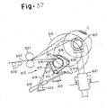
- FIG. 37 A conventional band plate winding system using a carrousel type winder is exemplified in Fig. 37 .
- a circular support frame 610 is installed at a delivery-side side portion of a rolling equipment line so as to be rotationally driven in a vertical plane.
- a plurality of mandrels 611 are supported horizontally via bearings.
- the drawing shows a case in which there are two mandrels 611.
- the support frame 610 is turned, as necessary, by an inherent driving system.
- the mandrels 611 on the support frame 610 are driven in a winding or unwinding manner by individual driving systems when a band plate is wound into or unwound from a coil C.
- a wrapping device 612 for a band plate 602 is provided which moves so as to surround or expose the mandrel 611.
- the wrapping device 612 is composed of a pair of arm-shaped frames 614 and a pair of arm-shaped frames 615 having one end rotatably mounted on a fixing base 613 via shafts and spreading around the mandrel 611, a belt or chain member 617 passed in an endless form over four guide rolls 616 supported on the pairs of arm-shaped frames 614 and 615 so as to contact the mandrel 611, and two cylinders 618 and 619 for driving both frames 614 and 615 to open and close.
- the cylinders 618 and 619 have cylinder portions rotatably supported on a fixing base 620 via shafts, and have driving ends rotatably attached to side portions of the frames 614 and 615 via shafts.
- the band plate coil C wound onto the other mandrel 611 is withdrawn from the mandrel 611, and carried by a trolley 621.
- the band plate 602 that has run on a roller table 600 of the rolling equipment line and has left a pinch roll 601 is guided to the mandrel 611 within the wrapping device 612. Then, the band plate 602 is pressed against an outer surface of the mandrel 611 under tension of the belt or chain member 617. During this action, the band plate 602 is formed into a band plate coil C by the winding action of the mandrel 611.
- the cylinders 618 and 619 are driven in a contracted manner to release the belt or chain member 617.
- the support frame 610 is turned 180° clockwise, and brought to a halt.
- the belt or chain member 617 is delivered to the surroundings of an unloaded mandrel 611.
- the band plate 602 which enters the band plate coil C supported on the mandrel 611 at the symmetrical position, is cut with a shear (not shown) disposed on the line.
- a front end of the cut band plate 602 is guided to the empty mandrel 611 inside the belt or chain member 617 to continue similar winding for forming a band plate coil C.
- a tail end of the cut band plate 602 on the band plate coil C side is taken up into the band plate coil C, and then, the winding action of the mandrel 611 is stopped.
- the band plate coil C on the mandrel 611 is extracted by a hoisting/lowering and traveling operation of the trolley 621, and carried to a next step.
- a high-temperature band plate 602 that has been hot rolled can be wound at a high rate expressed as "a plate speed of about 1,000 m/min".
- a plate speed of about 250 m/min is the maximum allowable running speed. This device cannot be used in equipment with a plate speed higher than that.
- an object of the present invention is to provide a band plate winding system capable of high speed winding at a low cost.
- a band plate winding system comprises a carrousel type winder having a plurality of individually driven mandrels on a circular support frame provided so as to be rotationally drivable in a vertical plane; and a roll type wrapping device for supporting a plurality of unit rolls each provided so as to be movable forward and backward between a position surrounding the mandrel located at a winding start position of the winder and a retreat position.
- the roll type wrapping device for supporting the plurality of unit rolls supports the unit rolls on a plurality of pivoting frames which pivot so as to be movable toward and away from a circumferential surface of the mandrel located at the winding start position; a first panel-like arm and a second panel-like arm are pivotably provided on at least one of the plurality of pivoting frames, the first panel-like arm having a band plate wrapping guide at a front end thereof, and the second panel-like arm having a band plate wrapping guide at a front end thereof and being provided with the unit roll; and a pivot shaft of the second panel-like arm is placed in a plane of lateral projection of the first panel-like arm at the winding start position.
- the distance between the shafts of the shaft-attached portion of the second panel-like arm and the unit roll can be enlarged.
- the panel-like arm can pivot smoothly, so that concentration of stress on the shaft-attached portion is resolved.
- the shaft-attached portions of the second panel-like arm are provided in a plane of projection of a head portion of the first panel-like arm at the winding start position.
- the head side of the first panel-like arm can pass between the shaft-attached portions of the second panel-like arm, and move toward and away from the mandrel.
- a band plate can be wound under high speed rolling to a degree comparable to that using a conventional down coiler even during hot rolling. Also, the scale of equipment, the size of an installation space, and the cost of equipment can be markedly decreased because of the concomitant use of the carrousel type winder.
- the winding start position for winding by the mandrel of the winder is at the same level as a pass line height of the band plate.
- the band plate delivered from a delivery side of a rolling equipment line can be smoothly fed to an empty mandrel located at the winding start position.
- the roll type wrapping device that supports the plurality of unit rolls is provided on a common shaft of a support base.
- the wrapping device can be placed appropriately so as to surround the mandrel.
- a unit roll driving device for rotationally driving each of the plurality of unit rolls comprises transmission means which transmits a rotational force of a driving motor in a direction nearly perpendicular to an axis of the unit roll and which pivots integrally with a frame for supporting the unit roll; one of connector portions of the transmission means is connected by a transmission shaft to an end of the unit roll opposed to the one connector portion; and the driving motor is connected to the other connector portion of the transmission means.
- the driving motor and the other connector portion of the transmission means can be connected together via a short transmission shaft or directly.
- the transmission shaft that connects the one connector portion of the transmission means to the end of the unit roll opposed to the one connector portion may be short in length, and can be held at a slight angle.
- the unit roll driving device for rotationally driving each of the plurality of unit rolls comprises a parallel plate provided, outside and apart from a frame for supporting the unit roll, so as to turn integrally with the frame; at least two bevel gear boxes provided on the parallel plate; a transmission shaft for connecting these bevel gear boxes together; a transmission shaft for connecting one of the bevel gear boxes to an end of the unit roll opposed to the one bevel gear box; and a transmission shaft for connecting the other bevel gear box to a driving motor via universal joints.
- the transmission shaft that connects the other bevel gear box to the driving motor via the universal joints can be shortened.
- the transmission shaft that connects the one bevel gear box to the end of the unit roll opposed to the one bevel gear box may be short in length, and can be held at a slight angle.
- a pair of bevel gears in the bevel gear box are constituted at a speed increasing gear ratio.
- the transmission shaft that connects the other bevel gear box to the driving motor via the universal joints is rotated at a relatively low speed.
- vibrations occurring in this transmission shaft are further suppressed to promote safety. Since the transmission shaft can be rotated at a low speed, moreover, a large allowable inclination angle can be taken for the transmission shaft, and the entire length of the transmission shaft can be shortened further.
- the unit roll driving device for rotationally driving the plurality of unit rolls comprises a gear support panel provided, outside and apart from a frame for supporting the unit rolls, so as to pivot integrally with the frame; multi-stage gears placed at a pivot center position on the gear support panel, at positions on nearly the same axes as the unit rolls, and between both of the positions, and mounted and supported on the gear support panel so as to mesh with each other; a driving motor connected to a shaft of the gear placed at the pivot center position among the multi-stage gears, thereby rotationally driving this gear; and transmission shafts for connecting shafts of the gears, placed at the positions on nearly the same axes as the unit rolls among the multi-stage gears, to ends of the unit rolls corresponding to the shafts of the gears.
- Short transmission shafts which connect the shafts of the gears, placed at the positions on nearly the same axes as the unit rolls, to the ends of the unit rolls corresponding to the shafts of the gears can be used at a small inclination angle.
- a system which can be operated safely at a high speed can be constructed in a compact size.
- a deflector device for guiding the band plate to the winder comprises an upper deflector roll disposed above a pass line of the band plate upstream of the winder; and upper guide means which is disposed forwardly and backwardly movably so as to be located above the pass line of the band plate between the winder and the upper deflector roll, and which has a lower surface whose upper deflector roll side can be positioned above a horizontal line in contact with a lower portion of the upper deflector roll, the lower surface of the upper guide means being an inclined surface sloping downward toward the winder.
- the front end of the band plate does not enter this spacing, but is positioned below the lower surface of the upper guide means and guided to the winder by this lower surface.
- the front end of the band plate can be guided to the winder reliably.
- An auxiliary deflector roll is provided which is disposed so as to be movable forward and backward integrally with the upper guide means, and which increases an angle of deflection of the band plate from the upper deflector roll.
- the spacing between the upper deflector roll and the upper guide means is set to be slightly greater than the thickness of the band plate. Even if the upper deflector roll side of the lower surface of the upper guide means is set at an even larger height, the auxiliary deflector roll increases the angle of deflection of the band plate from the upper deflector roll so that the upper guide means, etc. do not impede the traveling movement of the band plate. Hence, even if the front end of the band plate warps upward, the front end of the band plate can be guided to the winder more reliably.
- the roll type wrapping device for supporting the plurality of unit rolls is constituted such that of the plural unit rolls provided so as to be movable toward and away from the mandrel, the unit roll located above the mandrel is supported by an upper frame which moves toward and away from the mandrel from above the mandrel, while the other unit roll is supported by a lower frame which moves toward and away from the mandrel from below the pass line of the band plate.
- the unit roll positioned above the mandrel need not be supported by the lower frame.
- the length of the lower frame can be decreased to minimize a space necessary for forward and backward movement, so that the entire system can be downsized.
- First guide means for guiding a front end of the band plate to a wrapping entrance of the mandrel is provided on the upper frame.
- the band plate can be guided to the mandrel reliably by the first guide means.
- the upper frame is moved to a retracted position, a position at which the upper frame does not hinder the movement of the band plate.
- the upper frame does not contact the band plate being wound, so that damage to the band plate can be prevented.
- this front end is delivered to a suitable inclined or parallel posture relative to the pass line of the band plate.
- Second guide means facing the pass line of the band plate from above is provided pivotably between a rolling equipment side and the first guide means.
- the band plate can be guided to the mandrel further reliably by the second guide means.
- the second guide means is pivoted to an inclined state, whereby the second guide means can be brought to a position at which it does not hinder the movement of the band plate toward the mandrel.
- the second guide means does not contact the band plate being wound, so that damage to the band plate can be prevented.
- the second guide means is positioned below the first guide means, whereby the front end of a cut band plate can be guided to the wrapping entrance of the mandrel further reliably and safely.
- Interlocking means is provided for moving wrapping guide means backward in association with a backward movement of the unit roll supported by the lower frame, the wrapping guide means being provided, on a front end side of the lower frame opposed to a front end of the upper frame, so as to be movable toward and away from the mandrel.
- the interlocking means enables the wrapping guide means to recede in association with the backward movement of the unit roll supported by the lower frame. Hence, the front end of the band plate can be prevented from jamming between the wrapping guide means and the mandrel.
- the unit roll supported by the upper frame is larger in diameter than the unit roll supported by the lower frame.
- the band plate contacts the mandrel at the first entrance with a large roll curved surface, so that the front end of the band plate can be drawn in more reliably along an outer peripheral surface of the mandrel, and the front end of the band plate can be reliably brought upward or downward in an assorted manner.
- the front end of the band plate can be reliably brought upward or downward in an assorted manner. Hence, jamming of the front end of the band plate can be prevented further reliably.
- the roll type wrapping device for supporting the plurality of unit rolls is constituted such that a small cylinder for backup of the unit roll supported on a large frame via a panel-like arm among the plurality of unit rolls provided so as to be movable toward and away from a circumferential surface of the mandrel located at the winding start position has a built-in pressure oil chamber containing an amount of a pressure oil enough to absorb and cushion maximum impact force which the unit roll undergoes.
- the small cylinder for backup of the unit roll comprises an oil chamber for piston stroke having a rod side connected to the panel-like arm and a cylinder side connected to a large frame side, and having a required length for extending and contracting a piston rod; and an oil chamber for impact force cushioning provided to communicate with a head side of the oil chamber for piston stroke.
- the oil chamber for piston stroke and the oil chamber for impact force cushioning are connected together via an intermediate cover portion, and communicate with each other through a flow path inside the intermediate cover portion.
- an intermediate part of the long cylinder can be reinforced, and the cylinder can be mounted safely on the large frame by the intermediate cover portion.
- the roll type wrapping device for supporting the plurality of unit rolls comprises two unit roll support frames provided so as to derrick and pivot from an upstream side of a rolling equipment line about lower support shafts as centers of rotation until facing the mandrel at a wrapping start position, the two unit roll support frames being each in the form of a frame individually movable between a set mandrel facing position and a set retreat position without interference by each other.
- the. support frame for the upper unit roll is placed externally, while the support frame for the lower unit roll is placed internally, and a shape of the external support frame and a shape of the internal support frame are combined such that the internal support frame is movable to the retreat position when the external support frame has been brought to a band plate wrapping position at which the external support frame faces the mandrel.
- At least the inTernally placed support frame for the lower unit roll is mounted detachably on the support shaft by a semi-arcuate divided type boss portion.
- a driving shaft for each of the unit rolls is provided on a work side of a rolling equipment line, and a detachable mandrel front end support device is provided opposite a front end of the mandrel located at the winding start position, the mandrel front end support device having a sectional shape passing between the unit rolls facing a circumferential surface of the mandrel at the winding start position, and between unit roll driving systems, and the mandrel front end support device being movable parallel to an axis of the mandrel.
- the mandrel front end support device does not interfere with the driving system for the unit roll.
- the mandrel front end support device can be installed safely at the winding start position, and failure of band plate winding by the winder can be resolved.
- the detachable mandrel front end support device is adapted to be movably engaged on track elements fixedly placed on a support base in parallel with the axis of the mandrel, and to be moved to a position, at which the detachable mandrel front end support device is attached to or detached from the front end of the mandrel, by driving means placed on the support base.
- movement of the detachable mandrel front end support device can be performed easily.
- a parallel partition wall is provided, with the mandrel front end support device being sandwiched between the partition wall and a support frame for the unit roll, and pivots integrally with, but apart from, the support frame; and the unit roll driving system is provided, with the partition wall serving as an intermediate support point.
- Fig. 1 is a schematic side view of a band plate winding system showing a first embodiment not according to the present invention.
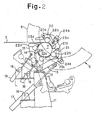
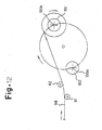
- Fig. 2 is an enlarged side view of an essential part of Fig. 1 .
- a carrousel type double-drum winder 5 is placed on a delivery side of a rolling equipment line.
- This winder 5 is composed of a circular support frame 6 to be rotationally driven in a vertical plane, and two individually drivable mandrels 7, 7 provided at symmetrical positions of the circular support frame 6.
- the two mandrels 7, 7 on the circular support frame 6 have a winding start position which is a pass line height position of a band plate 3 close to the delivery side of the rolling equipment line.
- a roll type wrapping device 10 is placed so as to be movable between a position, at which the wrapping device 10 surrounds the mandrel 7 stopped at the winding start position, and a retreat position at which the wrapping device 10 does not interfere with the turning of the circular support frame 6.
- the wrapping device 10 has three pairs of large and small arm-shaped frames (i.e., a pair of arm-shaped frames 13, a pair of arm-shaped frames 14 and a pair of arm-shaped frames 15) extending so as to surround the mandrel 7, with one end of each frame being supported by a common shaft 12 on a support base 11 placed below the mandrel 7 located at the winding start position and near the delivery side of the rolling equipment line; and three pairs of frame opening and closing cylinders (i.e., a pair of opening and closing cylinders 17, a pair of opening and closing cylinders 18, and a pair of opening and closing cylinders 19) each having a rod end connected to an outer portion of each of the frames 13 to 15, and having a cylinder portion connected onto the support base 11 by a shaft 16 in a configuration in which the cylinders pivot the frames 13 to 15 to the retreat position.
- three pairs of large and small arm-shaped frames i.e., a pair of arm-shaped frames 13, a pair of arm-shaped frames 14
- the pair of frames 13, as shown in Fig. 2 extend from below toward a rear surface of the mandrel 7 in a ⁇ -shape, and have at a front end portion and an intermediate portion thereof two panel-like arms 20, 21 connected at one end onto the frames 13 by shafts 20a and 21a.
- the two panel-like arms 20, 21 are provided, respectively, with a unit roll 22a and a presser plate 23a, and a unit roll 22b and a presser plate 23b, which come into contact with the band plate 3 wound onto the mandrel 7.
- small cylinders 24a, 24b are provided for pressing the unit rolls and the presser plates against a surface of the mandrel 7.
- the pair of frames 14 are in a size comparable to that of the panel-like arms 20, 21, extend to an outer lower half surface of the mandrel 7. Like the panel-like arms 20, 21, the frame 14 is provided with a unit roll 22c and a presser plate 23c, which are to be pushed against the surface of the mandrel 7 by the opening and closing cylinder 18.
- the pair of frames 15 extend to pass above the frame 14 and face an upper outer surface of the mandrel 7.
- the frame 15 is provided with a unit roll 22d and a presser plate 23d, which are to be pushed against the surface of the mandrel 7 by the opening and closing cylinder 19.
- the four unit rolls 22a to 22d and presser plates 23a to 23d are adapted to press the band plate 3 being wound by the mandrel 7 against the surface of the mandrel 7 at four circumferentially spaced locations with an adjusted force, thereby shaping it.
- a trolley 25 is provided for taking a coil C, wound onto the other mandrel 7 on the circular support frame 6, out of the mandrel 7 and carrying the coil C.
- the band plate winding system constituted as above is used in the following manner:
- the winder 5 turns the circular support frame 6 clockwise to send an empty mandrel 7 sequentially to the winding start position, and stops.
- the wrapping device 10 contracts the cylinders 17 to 19 to move the frames 13 to 15 to the retreat position indicated by dashed lines, and enters a wait state.
- the cylinders 17 to 19 are extended to bring the frames 13 to 15 to positions indicated by solid lines in the surroundings of the empty mandrel 7.
- the band plate 3 which runs on a roller table 1 and is delivered from a pinch roll 2 on the delivery side of the rolling equipment line, is guided by guide rollers onto the empty mandrel 7 located at the winding start position.
- the band plate 3 begins to be pressed by the unit rolls 22a to 22d of the wrapping device 10, and wound by the mandrel 7 at the same time, whereby a coil C of the band plate 3 is formed on the mandrel 7.
- the wrapping device 10 is released and moved to the retreat position shown by the dashed line.
- the circular support frame 6 of the winder 5 is turned a half turn clockwise to move an empty mandrel 7 to the winding start position and stop it there.
- the wrapping device 10 is sent to the solid-line position to make it ready for winding of a next band plate 3.
- the band plate 3 is cut with a shear on the delivery side of the rolling equipment line. A tail end side of the cut band plate 3 is guided by guide means, whereupon winding of the band plate 3 onto the mandrel 7 moved to an upper right position of the circular support frame 6 is completed. At this time, winding of this mandrel 7 is stopped.
- a front end of the cut band plate 3 is guided by guide rollers onto an empty mandrel 7 located at the winding start position, and the same winding of the band plate 3 as described above is repeated.
- the coil C on the upper right mandrel 7 that has finished winding is taken out by the trolley 25 from the mandrel 7, and carried to a subsequent step.
- the wrapping device 10 is constituted to be of a roll type having the plurality of unit rolls 22a to 22d.
- winding of the band plate 3 under high speed rolling at a speed as fast as "a plate speed of 1,000 m/min" can be performed as with a conventional down coiler ( Fig. 36 ).
- the carrousel type (double-drum type) winder 5 can be used concomitantly, so that the scale of equipment, the size of an installation space, and the cost of equipment can be markedly decreased.
- the foregoing embodiment shows an example in which the four unit rolls are present, but three or more unit rolls may be used.
- Fig. 3 is a schematic side view of a unit roll driving device showing a second embodiment not according to the present invention.
- Fig. 4 is a development sectional view taken along line I-I of Fig. 3 .
- the reference numeral 51 denotes a parallel plate.
- This parallel plate 51 is fixedly supported via a binding material 60 on an outside of a large frame 41 on a front end side of a mandrel 35, and is provided parallel at a distance from the large frame 41.
- the parallel plate 51 is also constituted to have a shape spreading along loci 37a, 37b ranging from positions at which it faces ends of two unit rolls 37, 37 on the large 'frame 41, to retracted positions 37', 37' to which the unit rolls 37, 37 on the large frame 41 move.
- the parallel plate 51 On an outer surface of the parallel plate 51, four bevel gear boxes 52 are fixed. Of them, the upper two bevel gear boxes 52 are placed at positions opposed to the ends of the unit rolls 37, 37 on the large frame 41, while the lower two bevel gear boxes 52 are placed at the other end and an obliquely lower portion of the parallel plate 51 along the loci 37a, 37b of the unit rolls 37, 37 on the large frame 41 moving to their retracted positions 37', 37'.
- the reference numeral 53 denotes a pair of perpendicularly intersecting bidirectional bevel gears rotatably supported in each bevel gear box 52 via bearings.
- the reference numeral 54 denotes a transmission shaft connected via universal joints 55 between an end portion of each of the unit rolls 37, 37 on the large frame 41 and a shaft end of the bevel gear 53 of the bevel gear box. 52 corresponding to the end portion.
- the reference numeral 56 denotes a transmission shaft fixedly connected between shaft ends of each pair of bevel gear boxes 52 along the movement loci 37a, 37b.
- the reference numeral 57 denotes a unit roll driving motor installed near the height of the parallel plate 51 when retracted.
- the reference numeral 58 denotes an output shaft of the driving motor 57.
- the reference numeral 59 denotes a transmission shaft connected via universal joints 55 between the end of a horizontal shaft of the lower bevel gear box 52 on the parallel plate 51 and the end of the motor output shaft 58.
- the upper bevel gear box 52 and the lower bevel gear box 52 are connected together by the transmission shaft 56.
- the upper bevel gear box 52 and the end of the unit roll 37 opposed to the upper bevel gear box 52 are connected together by the transmission shaft 54 via the universal joints 55.
- the lower bevel gear box 52 and the driving motor 57 are connected together by the transmission shaft 59 via the universal joints 55.
- the driving motor 57 is placed at a position at which the angle of inclination of the transmission shaft 59 is kept within 15°.
- Fig. 4 shows only the unit roll 37 located at the front end side of the large frame 41, and the driving system therefor. However, the same driving system as this one is constituted for the unit roll 37 on the intermediate portion side of the large frame 41.
- the other constitution is the same as in the first embodiment, and a detailed explanation will be omitted herein by reference to the first embodiment.
- the large frame 41 of a wrapping device 36 is moved between an operating position, which is opposed to a mandrel 35 moved to a winding start position 35a, and a retracted position 41' (see Fig. 6 ) upon extension and contraction of a driving cylinder 46.
- Other frames i.e., a medium frame 42 and a small frame 43, are also moved between the operating position and the retracted position simultaneously upon extension and contraction of driving cylinders 47, 48.
- the parallel plate 51 is moved between the operating position and the retracted position integrally with the large frame 41.
- the unit roll 37 is rotationally driven by the driving motor 57. That is, a rotational force of the driving motor 57 is transmitted to the bevel gear box 52 via the transmission shaft 59. Then, this force is transmitted by. the bevel gear box 52 and the transmission shaft 56 in a direction perpendicular to the axis of the unit roll 37. The force is further transmitted to the unit roll 37 by the transmission shaft 54.
- the transmission shaft 59 keeps a constant angle of inclination (e.g., 15°), with the universal joint 55 at the end of the motor output shaft 58 as a fixed point, and with the universal joint 55 at the end of the lower bevel gear box 52 as a moving point. In this manner, the transmission shaft 59 pivots between the operating position and the retracted position.
- the radius of pivoting, r can be reduced by a little more than 20% compared with conventional systems.
- the transmission shaft 59 is connected between the lower bevel gear box 52 and the driving motor 57.
- the length, 1, of the transmission shaft 59 is halved to a little more than about 5 m, as shown in Fig. 4 .
- the transmission shaft 54 between the upper bevel gear box 52 and the unit roll 37 may be short, and can be held at a slight angle of inclination, even if a gap allowance by the driving cylinder for the panel-like arm is included.
- the unit roll driving device of the present embodiment therefore, there can be provided a system of a compact size in which the length of the transmission shaft 59 for driving of the unit roll can be shortened to decrease vibrations, and which can be operated safely at a high speed with a large angle of inclination.
- Fig. 5 is a side view of the constitution of bevel gears of a unit roll driving device showing a third embodiment not according to the present invention.
- the driving device of this embodiment is the unit roll driving device of the second embodiment constituted with a change in the gear ratio of the pair of bevel gears 53 inside the bevel gear box 52.
- the reference 52 denotes a bevel gear box corresponding to the two unit rolls 37 on the large frame 41.
- bevel gears 61, 63 are provided as a pair of bevel gears 53.
- the bevel gear 61 is supported by a bearing 62 of the bevel gear box 52, and connected to a transmission shaft 54.
- the bevel gear 63 is supported by a bearing 62', and connected to a transmission shaft 56.
- Fig. 5 shows a case in which the gear ratio between the bevel gears 61 and 63 is set at 1/2, so that revolutions on the part of the transmission shaft 56 are doubled and transmitted to the transmission shaft 54 on the part of the unit roll 37.
- This gear ratio is not restricted to 1/2, but may be set as necessary.
- a speed increasing gear ratio may also be applied to the bevel gears of the lower bevel gear box 52 to increase the speed progressively.
- the transmission shaft 59 is rotated at a relatively low speed. Consequently, vibrations occurring in the transmission shaft 59 are further suppressed, and safety is enhanced. Since the transmission shaft 59 can be rotated at a low speed, the allowable angle of inclination of the transmission shaft 59 can be made large, and the entire length of the transmission shaft 59 can be shortened further.
- Fig. 6 is a schematic side view of a unit roll driving device showing a fourth embodiment not according to the present invention.
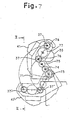
- Fig. 7 is an enlarged side view of a multi-stage gear transmission mechanism in Fig. 6 .
- Fig. 8 is a front view taken on line II-II of Fig. 7 .
- the reference numeral 71 denotes a gear support panel.
- the gear support panel 71 is fixedly supported via a binding material 72 on an outside of a large frame 41 at a front end side of a mandrel 35, and is provided in parallel with and apart from the large frame 41.
- the gear support panel 71 is formed in a ⁇ -shape in a range extending from a position at which it covers end portions of two unit rolls 37, 37 on the large frame 41, to a position at which it covers a support shaft 40 for the large frame 41.
- the gear support panel 71 contains six gears 73, 74, 75, 76, 77 and 78 meshing in multiple stages.
- gears 73 to 78 are each supported via a bearing (not shown) on the gear support panel 71, and are arranged in the ⁇ -shape as a whole. In Figs. 6 and 7 , these built-in gears 73 to 78 are illustrated in an exposed state.
- the first-stage gear 73 is supported by the gear support panel 71 coaxially with the support shaft 40 for the large frame 41.
- the shaft of this first-stage gear 73 is coupled via a coupling 81 to an output shaft 80 of a driving motor 79 provided on and adjacent a base 38.
- the shaft of this first-stage gear 73 is also supported by a bearing 82 on the base 38 together with the gear support panel 71.
- the fourth-stage gear 76 and the sixth-stage gear 78 have the same diameter, and are rotatably provided on the gear support panel 71 at positions nearly coaxial with the intermediate and upper unit rolls 37, 37 on the large frame 41.
- the second-stage gear 74 and the third-stage gear 75 are placed linearly between the first-stage gear 73 and the fourth-stage gear 76 to transmit a rotational force of the first-stage gear 73 to the fourth-stage gear 76.
- the fifth-stage gear 77 is placed linearly between the fourth-stage gear 76 and the sixth-stage gear 78 to transmit the rotational force.
- These multi-stage gears 73 to 78 may be arranged on a ⁇ -shaped line as stated above, or may be arranged zigzag with the second-, third- and fifth-stage gears being displaced right and left.
- the first-stage gear 73 to the fourth-stage gear 76 are shown to have the same diameter. However, these gears, from 73 to 76, may be gears having a speed increasing ratio.
- the reference numerals 83 and 84 denote extendable transmission shafts connected via universal joints 85 between the shafts of the fourth-stage gear 76 and the sixth-stage gear 78 and end portions of the unit rolls 37, 37 corresponding to these shafts. That is, the shafts of the gears 76, 78 at positions nearly coaxial with the unit rolls 37, 37 on the large frame 41, and the ends of the unit rolls 37, 37 corresponding to these gear shafts, are interconnected by the transmission shafts 83, 84.
- the reference numeral 86 in Fig. 8 denotes a moving bearing which attaches to or detaches from the front end of a mandrel 35.
- the other constitutions are the same as in the first embodiment, and a detailed explanation for them will be omitted by referring to the first embodiment.
- the large frame 41 of a wrapping device 36 is conveyed between an operating position, which is opposed to the mandrel 35 moved to a winding start position 35a, and a retracted position 41', by the extension and contraction of a driving cylinder 46.
- a medium frame 42 and a small frame 43 are also conveyed between an operating position and a retracted position by the extension and contraction of driving cylinders 47, 48.
- the gear support panel 71 is moved between an operating position and a retracted position integrally with the large frame 41.
- the output shaft 80 is driven at 1,400 rpm by the driving motor 79, the first-stage gear 73 is rotated at the same revolution speed. These revolutions are sequentially transmitted to the multi-stage gears 74 to 78, whereby the fourth-stage gear 76 and the sixth-stage gear 78 are rotated at the same speed in the same direction. That is, the rotational force of the driving motor 79 is transmitted by the multi-stage gears 73 to 78 in a direction perpendicular to the axis of the unit roll 37. Revolutions of the fourth-stage gear 76 and the sixth-stage gear 78 are transmitted to the unit rolls 37 via the transmission shafts 83, 84, respectively, whereupon the unit rolls 37 are rotated in the same direction at the same speed.
- the motor output shaft 80 is rotated at a low speed (e.g., 700 rpm), and the fourth-stage gear 76 and the sixth-stage gear 78 (accordingly, the unit rolls 37) can be rotated at a high speed (1,400 rpm).
- the gear support panel 71 may be provided at a position relatively close to the end of the mandrel 35.
- the transmission shafts 83, 84 interconnecting the unit rolls 37 to the fourth-stage gear 76 and the sixth-stage gear 78 may be used with a short length and a gentle angle of inclination.
- the transmission shafts 83, 84 can transmit a rotational force, necessary for winding of the band plate 33, to the two unit rolls 37, 37 in the same direction at the same speed.
- the entire system can be constituted in a very compact size.
- Arrangement of the multi-stage gears 73 to 78 on the " ⁇ -shaped" line facilitates the placement of the binding material 72 between the large frame 41 and the gear support panel 71.
- a circular support frame 34 is turned in a direction of an arrow A, whereupon the mandrel 35 at the winding start position 35a moves to a winding completion position 35b.
- An empty mandrel 35 at the winding completion position 35b moves to the winding start position 35a.
- the winding unit roll 37 is sent to the operatingposition again, and similar winding of the band plate 33 is repeated.
- a long transmission shaft is not required for the driving of the unit roll 37, and the short transmission shafts 83, 84 can be used with a small angle of inclination.
- a compact system which can be operated safely at a high speed can be provided.
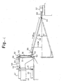
- Fig. 9 is a schematic side view of a deflector device showing a fifth embodiment not according to the present invention.
- a lower deflector roll 91 is disposed below a pass line of a band plate 98 beside a pinch roll 99 between the pinch roll 99 and a wrapping device 104.
- an upper deflector roll 92 is disposed above a pass line of the band plate 98 on the wrapping device 104 side (upstream of a winder 100) between the pinch roll 99 and the wrapping device 104.
- entrance guide means 93 is disposed below a pass line of the band plate 98 between the lower deflector roll 91 and the wrapping device 104.
- entrance guide means 93 is disposed.
- a front end of its downward guide surface 95a is positioned at a necessary and sufficient height, h 1 , from a horizontal line L 1 in contact with a lower part of the upper deflector roll 92. Furthermore, the downward guide surface 95a forms an inclined surface as a gently curved surface or a flat surface sloping downward toward mandrels 101, 102 of the winder 100.
- a gap, g, between the band plate 98, which runs sloping upward, beginning at the upper deflector roll 92, and the upper guide means 95 is set to be slightly greater than the thickness, t, of the band plate 98 (i.e., t + several millimeters).
- the upper guide means 95 is disposed forwardly and backwardly movably so that the upper guide means 95 can be located above the pass line of the band plate 98 between the winder 100 and the upper deflector roll 92.
- the upper deflector roll 92 side (front end) of its downward guide surface 95a (lower surface) can be positioned above the horizontal line L 1 , and the downward guide surface 95a forms an inclined surface sloping downward toward the winder 100.
- deflector device 90 of the present embodiment.
- the other constitutions are the same as in the first embodiment, and a detailed explanation for them will be omitted by reference to the first embodiment.
- the upper deflector roll 92 side of its downward guide surface 95a can be positioned above the horizontal line L 1 .
- the front end of the band plate 98 being fed at a high speed from the rolling equipment is not allowed to enter this spacing w 1 , but can be positioned below the downward guide surface 95a of the upper guide means 95.
- the downward guide surface 95a of the upper guide means 95 forms an inclined surface sloping downward toward the winder 100.
- the front end of the band plate 98 can be guided to a wrapping entrance of the mandrels 101, 102 at a winding start position 100a.
- the band plate 98 can be continuously wound.
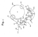
- Fig. 10 is a schematic side view of a deflector device showing a sixth embodiment not according to the present invention.
- Fig. 11 is an explanation view of the operation of the deflector device.
- Fig. 12 is an explanation view of the operation of the deflector device subsequent to the operation of Fig. 11 .
- Fig. 13 is an explanation view of the operation of the deflector device subsequent to the operation of Fig. 12 .
- Fig. 14 is an explanation view of the operation of the deflector device subsequent to the operation of Fig. 13 .
- a large frame 105a of a wrapping device 104 is extended as follows: When unit rolls 106a, 106b (see Fig. 11 ) of the large frame 105a are stopped with a predetermined spacing from and around a mandrel 101 or 102 at a winding start position 100a (i.e., in the operating state), a front end of the large frame 105a is located nearer to an upper deflector roll 92 than in the case of the large frame 105a of the preceding embodiment.
- upper guide means 96 is provided at the front end of the large frame 105a.
- the upper guide means 96 is constituted such that a horizontal spacing w 2 between its front end and the upper deflector roll 92 is set to be smaller than the horizontal spacing w 1 between the upper deflector roll 92 and the upper guide means 95 in the preceding embodiment so that it will be slightly greater than the thickness, t, of a band plate 98 (i.e., t + several millimeters).
- the front end of its downward guide surface 96a is positioned at a height, h 2 , greater than the height h 1 in the preceding embodiment.
- an auxiliary deflector roll 97 is provided rotatably.
- the auxiliary deflector roll 97 is held at such a position that its center makes a predetermined deflection angle ⁇ (e.g., 60°) for upward deflection from the center of the upper deflector roll 92, in a state in which the unit rolls 106a, 106b of the large frame 105a are stopped with a predetermined spacing from and around the mandrel 101 or 102 at the winding start position 100a (i.e., in the operating state).
- ⁇ e.g. 60°
- the auxiliary deflector roll 97 is disposed so as to be movable forward and backward integrally with the upper guide means 96, and increases the angle of deflection of the band plate 98 from the upper deflector roll 92.
- lower deflector roll 91, upper deflector roll 92, entrance guide means 93, lower guide means 94, upper guide means 96, and auxiliary deflector roll 97 together constitute a deflector device 90 according to the present embodiment.
- the other constitutions are the same as in the first embodiment, and a detailed explanation for them will be omitted by reference to the first embodiment.
- the horizontal spacing w 2 between the front end of the upper guide means 96 and the upper deflector roll 92 is set to be slightly greater than the thickness, t, of the band plate 98 (i.e., t + several millimeters), and the front end of the downward guide surface 96a of the upper guide means 96 is positioned at the height h 2 which is larger than the aforementioned height h 1 .
- a wrapping device 104 is retreated as shown in Fig. 11 .
- a circular support frame 103 (see Fig. 14 ) is turned to move the mandrel 101 to a winding completion position 100b (see Fig. 12 ).
- an empty mandrel 102 at the winding completion position 100b is moved to the winding start position 100a.
- the band plate 98 is wound onto the mandrel 101 while being caused to run in a deflected manner in an upwardly inclined direction under the action of the upper deflector roll 92.
- Fig. 11 With the mandrel 101 being driven to wind the band plate 98, a circular support frame 103 (see Fig. 14 ) is turned to move the mandrel 101 to a winding completion position 100b (see Fig. 12 ).
- an empty mandrel 102 at the winding completion position 100b is moved to the winding start position 100a.
- the band plate 98 is wound onto the mandrel 101 while being caused to
- the wrapping device 104 is advanced to the original operating position, and set again.
- the auxiliary deflector roll 97 of the deflector device 90 contacts a lower surface of the band plate 98 being wound, pushing the band plate 98 upward.
- the band plate 98 is deflected so that the large frame 105a and the upper guide means 96 do not impede the travel of the band plate 98.
- the band plate 98 is cut with a cutter (shear) which is not shown.
- a preceding band plate 98 is wound onto the mandrel 101 at the winding completion position 100b, while the front end of a succeeding band plate 98 is guided by the deflector device 90 to a wrapping entrance of the mandrel 102 at the winding start position 100a, and wound onto the mandrel 102 (see Fig. 14 ). Subsequently, the same action as above is repeated.
- the horizontal spacing w 2 between the front end of the upper guide means 96 and the upper deflector roll 92 is set to be slightly greater than the thickness, t, of the band plate 98 (i.e., t + several millimeters), and the front end of the downward guide surface 96a of the upper guide means 96 is positioned at the height h 2 which is greater than the aforementioned height h 1 .
- the auxiliary deflector roll 97 is provided so that the large frame 105a and the upper guide means 96 do not impede the travel of the band plate 98. By this measure, the angle of deflection of the band plate 98 from the upper deflector roll 92 is increased.
- the band plate 98 can be guided more reliably, than in the aforementioned embodiment, to the wrapping entrance of the mandrel 101 or 102 at the winding start position 100a. Hence, the band plate 98 can be continuously wound more reliably.
- Fig. 15 is a schematic side view of a band plate winding system showing a seventh embodiment not according the present invention.
- the reference numeral 110 denotes a roll type wrapping device disposed in combination with a carrousel type winder 210.
- the wrapping device 110 comprises a pair of arcuate lower large frames 113, a pair of arcuate lower medium frames 114 and a pair of arcuate lower small frames 115 having one end pivotably supported on a support shaft 111 so as to be movable toward and away from a mandrel 212 at a winding start position 210a below a pass line of a band plate 200; an upper frame 116 having one end pivotably supported on a support shaft 112 so as to be movable toward and away from the mandrel 212 at the winding start position 210a above the pass line of the band plate 200; a unit roll 117, a unit roll 118, a unit roll 119 and a unit roll 120 supported on the frames 113 to 116, respectively; cylinders 121 to 124 for moving the frames 113 to 116 back and forth about the support shafts 111
- lower guide means 131 At a front end of the lower medium frame 114, lower guide means 131 is provided. At a band plate 200 entry side of the lower guide means 131, entrance guide means 132 is independently disposed. According to the present embodiment, the wrapping guide arm 127, small cylinder 128, etc. constitute winding guide means.
- the band plate 200 winding action of the carrousel type winder 210 combined with the roll type wrapping device 110 is described below.
- the frames 113 to 116 and unit rolls 117 to 120 of the wrapping device 110 are each set at a solid line position opposed to the mandrel 212 of the winder 210. Then, when the band plate 200 is fed from rolling equipment, the mandrel 212 and the unit rolls 117 to 120 are driven and rotated in a winding direction to wind the band plate 200 around the mandrel 212.
- the frames 113 to 116 move to positions outside a locus of revolution of the mandrel 212 (i.e., to positions indicated by chain lines) according to the turning of a circular support frame 211.
- the mandrel 212 moves to a winding completion position 210b while being driven to perform winding.
- an empty mandrel 213 at the winding completion position 210b moves to the winding start position 210a.
- the upper frame 116 moves to an upper retracted position (indicated by a chain line).
- the band plate 200 from the rolling equipment is deflected in an upwardly inclined manner at a pinch roll 203, and wound round the mandrel 212 at the winding completion position 210b.
- the frames 113 to 116 are each set again at the original operating position (indicated by a solid line) opposed to the mandrel 213.
- the unit roll 120 on the upper frame 116 contacts an upper surface of the band plate 200, and is set at the original operating position (indicated by a solid line) while pushing the band plate 200 downward.
- the band plate 200 Upon sensing of a predetermined winding length of the band plate 200, the band plate 200 is cut with a cutter 202. A preceding band plate 200 is wound onto the mandrel 212 at the winding completion position 210b. Whereas the small cylinder 128 of the wrapping guide arm 127 and the small cylinder 130 of the arm 129 are actuated synchronously, whereupon the unit roll 120 and the wrapping guide arm 127 act cooperatively, thereby winding a succeeding band plate 200 round the mandrel 213.
- the unit roll 120 on the upper frame 116 enables the band plate 200 to be deflected in an upwardly inclined direction, and also the band plate 200 to be directed in a different direction.
- the band plate 200 is wound round the mandrel 212 of the winder 210, while the wrapping device 110 is reset around the other empty mandrel 213, the band plate 200 is no more damaged. Besides, it becomes possible to wind the rear end of the preceding band plate 200 on the winding completion position 210b side, and the front end of the succeeding band plate 200 on the winding start position 210a side, reliably in a divided manner.
- the unit roll 120 to be located at the upper winding entrance of the mandrel 213 is supported by the upper frame 116.
- the length of the lower large frame 113 can be shortened, so that the range of movement of the lower large frame 113 during retraction can be decreased.
- the diameter of revolution of the mandrel 212 or 213 according to the turn of the circular support frame 211 can also be decreased, so that the diameter of the circular support frame 211 can be reduced.
- the maximum diameter of a coil taken up by the mandrel 212 or 213 is a constant value of 2.1 m, for example, the diameter of revolution of the mandrel 212 or 213 according to the turn of the circular support frame 211 needs to be set at about 2.7 m in the case of the conventional system.
- the diameter of revolution of the mandrel 212 or 213 according to the turn of the circular support frame 211 may be about 2.3 m.
- the circular support frame 211 of the carrousel type winder 210 can be reduced by about 15% compared with the conventional system.
- Fig. 16 is a side view of an essential part of a band plate winding system showing an eighth embodiment not according to the present invention.
- first guide means 140 for guiding a front end of a band plate 200 from rolling equipment to a wrapping entrance of a mandrel 212 or 213 is provided at a front end portion of the upper frame 116 indicated in the preceding embodiment.
- the first guide means 140 comprises a moving guide plate 141 having one end attached pivotably to a front end of the upper frame 116 and extending toward the rolling equipment; a tilting small cylinder 142 connected by a shaft between the other end side of the moving guide plate 141 and the upper frame 116; and a fixed guide plate 143 fixed to the upper frame 116 in a manner continued from a base end of the moving guide plate 141.
- the band plate 200 can be reliably guided to the mandrel 212 by the moving guide plate 141 and fixed guide plate 143 of the first guide means 140. Furthermore, the small cylinder 142 is actuated to lift the moving guide plate 141 (to a chain line position in Fig. 16 ) and move the upper frame 116 to a retracted position. By so doing, the first guide means 140 can be held at a position at which it does not impede the movement of the band plate 200 from a pinch roller 203 toward the mandrel 212 at a winding completion position 210b. When the mandrel 212 has moved to the winding completion position 210b, therefore, the first guide means 140 does not contact the band plate 200 being wound, and damage to the band plate 200 can be prevented.
- the upper frame 116 is pushed outward to an operating position (indicated by a solid line) to guide a front end of a cut band plate 200 toward the mandrel 213 located at a winding start position 210a.
- the moving guide plate 141 is brought to a suitable inclined or parallel posture relative to a pass line of the band plate 200.
- Fig. 17 is a side view of an essential part of a band plate winding system showing a ninth embodiment not according to the present invention.
- second guide means 150 opposed from above to a pass line of a band plate 200 is pivotably disposed on an entry side of the first guide means 140 in the preceding embodiment, i.e., between a rolling equipment side and the first guide means 140, so as to be continued from the first guide means 140.
- the second guide means 150 comprises a moving guide plate 151 which has one end attached upwardly and downwardly pivotably to a stand or the like of a pinch roll 203 above an upwardly inclined pass line of the band plate 200 heading from the pinch roll 203 toward a mandrel 213 at a winding completion position 210b, and which extends to a position close to or overlapping an entry-side end of the first guide means 140; and a tilting small cylinder 152 connected by a shaft between the other end side of the moving guide plate 151 and an upper fixed structure.
- the band plate 200 can be further reliably guided to a mandrel 212 by the first guide means 140 and the second guide means 150.
- a small cylinder 142 of the first guide means 140 is actuated to lift a moving guide plate 141 and move an upper frame 116 to a retracted position.
- the small cylinder 152 of the second guide means 150 is actuated to lift the moving guide plate 151 for a constant stroke in an inclined manner.
- the guide means 140 and 150 can be held at positions at which they do not impede the movement of the band plate 200 from the pinch roller 203 toward the mandrel 212 at the winding completion position 210b.
- the guide means 140 and 150 do not contact the band plate 200 being wound, and damage to the band plate 200 can be prevented.
- Fig. 18 is a side view of an essential part of a band plate winding system showing a tenth embodiment not according to the present invention.
- a safety plate 163, as interlocking means, is provided so as to face the arm 125 with a slight gap present between the safety plate 163 and the arm 125.
- the front end of the band plate 200 can be prevented from jamming between the wrapping guide plate 161 and the mandrel 213.
- Fig. 19 is a side view of an essential part of a band plate winding system showing an eleventh embodiment not according to the present invention.
- a unit roll 120' of the upper frame 116 in the previous embodiment is larger in diameter than other unit rolls 117 to 119.
- a band plate 200 contacts a mandrel 212 or 213 at the first entrance on a large roll curved surface of the unit roll 120', so that the front end of the band plate 200 can be drawn in more reliably, than in the case of the unit roll 120 used in the previous embodiment, along an outer peripheral surface of the mandrel 212 or 213. Moreover, the front end of the band plate 200 can be reliably brought upward or downward in an assorted manner.
- the front end of the band plate 200 can be reliably brought upward or downward in an assorted manner. Hence, jamming of the front end of the band plate 200 can be prevented further reliably.
- Fig. 20 is a sectional view of a small cylinder for a unit roll support arm showing a twelfth embodiment not according to the present invention.
- Fig. 21 is a side view showing a state of mounting of the small cylinder.
- the reference numeral 220 denotes a small cylinder for backing up a unit roll 259 shown in the tenth and eleventh embodiments.
- the small cylinder 220 is composed of a rod-side cylinder cover 221, an intermediate cover 222, a head-side cover 223, and two cylinder barrels 224, 225 provided in series between these covers.
- the reference numeral 226 denotes a rod.
- the reference numeral 227 denotes a piston.
- the reference numeral 228 denotes a piston stroke oil chamber inside the cylinder barrel 224.
- the reference numeral 229 denotes a through-hole inside the intermediate cover 222.
- the reference numeral 230 denotes a head-side cushioning oil chamber formed in the cylinder barrel 225 so as to communicate with the piston stroke oil chamber 228 via the through-hole 229.
- the reference numeral 231 denotes a longitudinal shaft for support of the small cylinder 220 on a large frame.
- the stroke length, S, of the piston stroke oil chamber 228 is the same as the length in the conventional system that is the sum of a necessary forward or backward movement amount, L, of the unit roll 259 during winding of a band plate and an allowance ⁇ .
- the head-side cushioning oil chamber 230 has a length over which to contain an amount of a pressure oil enough to cushion maximum impact force that the unit roll 259 undergoes from a band plate 200 side.
- Fig. 21 shows a case in which the small cylinder 220 produced on an actual machine basis with the above-mentioned constitution is applied onto a lower large frame 233 of the roll type wrapping device in the tenth and eleventh embodiments.
- the small cylinder 220 of the above-mentioned constitution can be used in place of the small cylinder 24b in the wrapping device of the first embodiment. In either case, the small cylinder 220 can be mounted on the large frame whose shape is unchanged or slightly changed.
- the cylinder 220 can be mounted on the lower large frame safely, at the intermediate cover 222.
- the pressure oil chamber containing an amount of a pressure oil capable of cushioning maximum impact force imposed on the unit roll 259 is provided on the head side of the piston rod of the small cylinder 220.
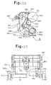
- Fig. 22 is a side view of two frame portions on an upstream side of a rolling equipment line showing a thirteenth embodiment not according to the present invention.
- Fig. 23 is a front view of the frame portions in Fig. 22 .
- Fig. 24 is an enlarged side view of the III portion in Fig. 22 .
- Fig. 25 is a front view taken on line IV-IV of Fig. 24 .
- Fig. 26 is an explanation view of the operation of the frame portions in Fig. 22 .
- Fig. 27 is another explanation view of the operation of the frame portions in Fig. 22 .
- the reference numeral 301 denotes a mandrel resting statically at the winding start position 301a in the tenth and eleventh embodiments.
- the reference numerals 362, 363 denote two (i.e., upper and lower) rolls facing a side surface, on a rolling line upstream side, of the mandrel 301.
- the reference numeral 352 denotes a support shaft shared by a large frame 113 (see Fig. 18 ) below the mandrel 301.
- the reference numeral 311 denotes a support shaft additionally provided on a rolling line upstream side of the support shaft 352.
- the reference numeral 312 denotes a frame for supporting the unit roll 362, the frame having a lower end pivotably supported by the support shaft 311.
- the reference numeral 313 denotes a frame for supporting the unit roll 363, the frame having a lower end pivotably supported by the support shaft 352.
- the support shaft 352 is fixedly supported by a bearing 352a, while the support shaft 311 is rotatably provided on a bearing 311a via a bearing.
- the support frame 312 is provided externally so as to be pivotable by having an upper central rear portion connected to a rod end of a cylinder 367.
- the support frame 313 is provided internally so as to be pivotable by having an upper central rear portion connected to a rod end of a cylinder 368 which passes through an opening portion 314 of the support frame 312, as shown in Figs. 22 and 23 .
- lower rear surface portions of both side plates thereof which support the unit roll 363 and a band plate wrapping guide member 365 are each a concave curved surface portion 315 in a panel-like form so as not to interfere with the support shaft 311 at an adjacent position during retreating movement.
- both side plates which support the unit roll 362 and a band plate wrapping guide member 364 are each shaped like a panel.
- the opening portion 314 is formed in a lower portion between both side plates.
- An upper half of the support frame 313 can come in and go out of the opening portion 314.
- a concave curved surface portion 316 is formed at an inner edge portion of both side plates of the external support frame 312.
- the concave curved surface portion 316 is designed such that when the internal support frame 313 is moved to a set retreat position with the external support frame 312 being set at a band plate winding position, the external support frame 312 does not contact or interfere with the unit roll 363 of the internal support frame 313.
- a shaft-attached portion at a lower end of the internal support frame 313 is constituted such that a boss portion fitted onto an outer surface of a bearing on the support shaft 352 has a semi-arcuate split piece 317.
- the semi-arcuate split piece 317 is joined to the boss portion on the frame 313 body side by screws 318 while sandwiching the bearing on the support shaft 352, whereby the frame 313 can be fixed detachably to the support shaft 352.
- Fig. 26 shows a state in which after the aforementioned two pivotable frames 312 and 313 upstream of the mandrel are set in the band plate winding position, only the internal pivotable frame 313 is moved to the set retreat position.
- Fig. 26 shows a case in which while the unit roll 362 of the external frame 312 is in contact with the coil surface, the unit roll 363 of the internal frame 313 precedes, and moves to the retreat position.
- the unit roll 363 of the internal frame 313, as shown in Figs. 22 and 26 sets as a predetermined retreat position a position in the concave curved surface 316 of the external frame 312 held in a condition in contact with the coil surface. By detecting its moving distance or the like by means of a detector, the unit roll 363 is allowed to move to the retreat position without contacting the external frame 312.
- clearances C 1 , C 2 in agreement with the pivoting distance of the external frame 312 corresponding to the coil thickness 300a are retained between the concave curved surface portion 315 of the internal frame 313 and the support shaft 311, and between the concave curved surface portion 316 of the external frame 312 and the unit roll 363, respectively.
- the clearance C 2 is set to be kept minimal when only the external frame 312 is pivoted and returned to the wrapping position relative to the empty mandrel 301, as shown in Fig. 22 .
- Fig. 27 shows a case in which the external frame 312 and the internal frame 313 are synchronously moved to a retreat position.
- the external frame 312 sets as a retreat position a position at which the external frame 312 is apart by a certain distance, as illustrated, from the surface of the band plate wrapping thickness 300a on the mandrel 301. With its moving distance or the like being detected by a detector, the external frame 312 is moved to the retreat position. At this time, the internal frame 313 is moved to the same retreat position as shown in Fig. 26 , and stopped there.
- the clearance C 1 between the concave curved surface portion 315 of the internal frame 313 and the support shaft 311 of the external frame 312 is kept minimal in this state.
- the mandrel 301 during winding of the band plate 300 revolves clockwise according to the turning of the circular support frame while winding the band plate 300. In this manner, this mandrel 301 is replaced by an empty mandrel 301 located at the winding completion position.
- the attachment boss portion of at least the internal frame 313 for attachment to the support frame 352 is shaped like the semi-arcuate split form 317, and is adapted to be detachably secured to the support frame 352 by the screws 318.
- attachment and detachment of the internal frame 313 become markedly easy for maintenance, etc.
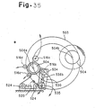
- Fig. 28 is a side view of an essential part of a band plate winding system showing a fourteenth embodiment according to the present invention.
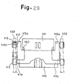
- Fig. 29 is a front view taken on line V-V of Fig. 28 .
- Fig. 30 is a side view of the band plate winding system in Fig. 28 .
- the reference numeral 401 denotes a roller table of a rolling equipment line
- 402 denotes a plate cutter on a delivery side of the line
- 403 denotes a pinch roll
- 404 denotes a rolled band plate
- 406 denotes a carrousel type winder
- 450 denotes a roll type wrapping device placed in combination with the carrousel type winder 406.
- the carrousel type winder 406 and the roll type wrapping device 450 constitute a band plate winding system.
- the carrousel type winder 406 is composed of a circular support frame 407 placed at a side portion on the delivery side of the line so as to be rotationally drivable, and two mandrels 408, 408 supported at symmetrical .positions of the circular support frame 407 individually rotationally drivable about a horizontal axis.
- the reference numeral 408a denotes a winding start position of the mandrel 408, while the reference numeral 408b denotes a winding completion position of the mandrel 408.
- the wrapping device 450 has a pair of arcuate piece-like lower large frames (pivoting frames) 433, a pair of arcuate piece-like medium frames (pivoting frames) 454, and a pair of arcuate piece-like small frames (pivoting frames) 455, each frame having one end supported pivotably on a support shaft 452 on a base 451.
- a second panel-like arm 410 and a first panel-like arm 411 having both ends pivotably supported are mounted.
- wrapping guide members 461, 460 are provided on front end portions of the second panel-like arm 410 and the first panel-like arm 411.
- a unit roll 459 is also provided on the second panel-like arm 410.
- a unit roll 462 and a unit roll 463 having both ends supported are provided, and wrapping guide members 464, 465 are also provided.
- cylinders 466, 467, 468 to be moved back and forth around the support shaft 452 are connected.
- small cylinders 441, 470 for moving toward and away from a mandrel side on the frames 433 are connected.
- An upper frame 434 has one end pivotably supported by a horizontal shaft 436 on an upper base 435, and has the other end on which a panel-like arm 438 is provided so as to be pivotable by a small cylinder 439.
- a cylinder 437 is connected to an intermediate portion of the upper frame 434.
- the upper frame 434 is pivoted so as to be movable toward and away from the mandrel 408.
- an upper-side unit roll 458 having both ends supported is independently provided.
- the circular support frame 407 and the mandrels 408, 408 are moved in a direction of an arrow A, with the frames 433, 434, 454, 455 of the wrapping device 450 being open at positions shown by one-dot chain lines.
- the unit rolls 458, 459, 462, 463 and the wrapping guide members 460, 461, 464, 465 are set, as shown by solid lines, around this mandrel 408. At this time, winding of a rolled band plate 404 is started.
- the frames 433, 434, 454, 455 of the wrapping device 450 become open at the positions shown by the one-dot chain lines.
- the circular support frame 407 revolves in the direction of arrow A. According to this revolution, the mandrel 408 also moves along the periphery of the circular support frame 407 while winding the band plate 404.
- the mandrel 408 stops at the winding completion position 408b winding of the band plate 404 is finished. Then, winding of the band plate 404 around the mandrel 408 at the winding start position 408a is repeated by the same procedure as described above.
- the second panel-like arm 410 is composed of a U-shaped panel-like arm body, and has.shaft-attached portions 410a at protruding ends of its U shape.
- the first panel-like arm 411 is composed of a roughly I-shaped panel-like arm body, and has shaft-attached portions 411a at its lower jutting portions. On its upper jutting portion, the wrapping guide member 460 is provided. The upper head side of the first panel-like arm 411 passes through a U-shaped space defined by the second panel-like arm 410, and faces a surface of the mandrel 408.
- the shaft-attached portions 410a of the second panel-like arm 410 are provided in a plane of projection of a head portion 411b of the first panel-like arm 411 at the winding start position, and the first panel-like arm 411 and the second panel-like arm 410 are constituted as above.
- the head side of the first panel-like arm 411 can pass between the shaft-attached portions 410a and 410a of the second panel-like arm 410, and move toward and away from the mandrel 408.
- the shaft-attached portion 410a of the second panel-like arm 410 is supported on a fixing shaft 412 which is supported via a bearing 413a by a bearing 413 provided on the lower large frame 433.
- the shaft-attached portion 411a of the first panel-like arm 411 is also supported via a bearing 413a by a bearing 413 provided on the lower large frame 433.
- the head side of the first panel-like arm 411 can freely move back and forth in the U-shaped space between the shaft-attached portions 410a of the second panel-like arm 410.
- the length, including the shaft-attached portions 410a, of the second panel-like arm 410 can be designed freely, without interference with the first panel-like arm 411.
- the shaft-attached portion 410a of the second panel-like arm 410 can be supported on the lower large frame 433 in an outward open free space.
- the center distance S between the unit roll 459 and the shaft-attached portion 410a of the second panel-like arm 410 can be made great.
- the shaft-attached portion 410a can be safely supported by the bearing 413, etc. on the lower large frame 433. Consequently, when a reaction force of the band plate is imposed on the unit roll 459, the second panel-like arm 410 can pivot smoothly counterclockwise, so that concentration of stress on the shaft-attached portion 410a and damage thereto are resolved.
- Fig. 31 is a front view of a band plate winding system showing a fifteenth embodiment not according to the present invention.
- Fig. 32 is a side view taken on line VI-VI of Fig. 31 .
- Fig. 33 is a side view taken on line VII-VII of Fig. 31 .
- a wrapping device 505 at a winding start position 504a is provided with four unit rolls 516a, 516b, 516c, 516d.
- the unit roll 516a on an upper side has both ends supported on a frame 518a turning upward about a support shaft 517a.
- the unit rolls 516b, 516c, 516d on a lower side each have both ends supported on frames 518b, 518c and 518d turning downward about support shafts 517b and 517d.
- a detachable mandrel front end support device 520 is provided on a support base 521 on a work side W s of the wrapping device 505.
- the mandrel front end support device 520 has a contour formed in a rail sectional shape.
- Each unit roll driving system 522 is placed along a side portion of the mandrel front end support device 520, and is placed between the shaft ends of the unit rolls 516a to 516d and each support base 523 apart on the work side.
- the mandrel front end support device 520 is supported on two track elements 524 provided parallel in a mandrel shaft direction on the support base 521, and is connected to a horizontal driving cylinder 525 provided on the support base 521. Upon driving of the cylinder 525, the mandrel front end support device 520 is moved in a switching manner to a mounting position or a dismounting position in an axial direction of a mandrel 504.
- the mandrel front end support device 520 has a lower portion spreading over and spanning the two track elements 524.
- a portion of the mandrel front end support device 520 passing between the unit rolls 516b and 516c forms a waist portion with a narrow width, and extends upward.
- An upper portion of the mandrel front end support device 520 forms a transverse cylindrical mandrel front end receiving portion.
- the entire contour of the mandrel front end support device 520 is in the shape of a rail section.
- Each driving system 522 for the unit roll is composed of a motor 526 placed on the support base 523 apart on the work side, and an extendable transmission shaft 528 connected between an output shaft end of the motor 526 and a shaft end of the unit roll via universal joints 527.
- Fig. 33 shows an arrangement relationship of the mandrel front end support device 520 and the unit roll driving systems 522 as viewed sideways.
- the four driving motors 526 are arranged at positions near the axes of the support shafts 517a, 517b and 517d for the unit rolls.
- the transmission shafts 528 and the four unit rolls 516a, 516b, 516c, 516d connected to the driving motors 526 are each arranged in such a manner as to keep a clearance from the upper portion and the waist portion of the mandrel front end support device 520.
- a mandrel front end support device 510 At a winding completion position 504b, a mandrel front end support device 510, and a carrier trolley 511 for coil extraction are provided.
- the other constitutions are the same as in the first embodiment, and a detailed explanation therefor is omitted by reference to the first embodiment.
- the action of the wrapping device 505 of the above-described constitution will now be described.
- the mandrel front end support device 520 is moved, by extension and contraction of the driving cylinder 525, to a position shown by a solid line and a position shown by a chain line in Fig. 31 .
- the driving cylinder 525 Upon contraction of the driving cylinder 525, the mandrel front end support device 520 moves to the solid line position apart from the front end of the mandrel 504, and enters a wait state.
- the unit rolls 516a, 516b, 516c, 516d are each moved backward in a direction of an arrow to a position apart from the mandrel 504, and put on standby.
- a circular support frame 503 is turned, whereby the mandrel 504 can be freely made to make a revolving movement between the winding start position 504a and the winding completion position 504b.
- the unit rolls 516a, 516b, 516c, 516d are sent to face a peripheral surface of the empty mandrel 504.
- the mandrel front end support device 520 is brought to the chain line position to support the front end of the mandrel, completing preparations for winding of a band plate.
- the unit rolls 516a, 516b, 516c, 516d and the transmission shafts 528 remain spaced from the mandrel front end support device 520, and can move between the solid line position and the chain line position, without touching the mandrel front end support device 520.
- the mandrel 504 and the unit rolls 516a, 516b, 516c, 516d are rotationally driven, and a band plate is fed from the rolling line to a space between the unit rolls 516a, 516b and the mandrel 504, whereupon the band plate is wrapped about the mandrel 504.
- the transmission shafts 528 rotate while keeping spaced from the mandrel front end support device 520.
- both ends of the mandrel 504 are supported.
- warpage of the front end of the mandrel 504 due to impact by the incoming band plate at the start of winding is resolved, and deviated winding of the band plate in the axial direction is also eliminated.
- the mandrel front end support device 520 is moved backward to the solid line position upon contraction of the driving cylinder 525. Also, the unit rolls 516a, 516b, 516c, 516d are withdrawn to retracted positions. In this state, the mandrel 504 at the winding start position 504a continues to wind the band plate, and is moved revolvingly to the winding completion position 504b in accordance with the turning of the circular support frame 503. Synchronously with this movement, the empty mandrel 504 that has a coil taken out at the winding completion position 504b is moved to the winding start position 504a.
- the mandrel front end support device 520 is brought to a position at which it supports the front end of the empty mandrel 504. Also, the unit rolls 516a, 516b, 516c, 516d are each brought to a position opposed to the mandrel 504 to be ready for next winding of the band plate.
- the front end of the mandrel 504 is supported by the front end support device 510 to perform winding of the band plate.
- a front end of the band plate cut on the rolling line is supplied to the empty mandrel 504 on standby. In this manner, wrapping of a next band plate is repeated, and extraction of a coil that has been wound at the winding completion position 504b is repeated.
- the mandrel front end support device 520 can be safely placed at the winding start position 504a without its interference with the unit roll driving system. Thus, a failure in winding of a band plate by the winder can be resolved.
- Fig. 34 is a front view of a band plate winding system showing a sixteenth embodiment not according to the present invention.
- Fig. 35 is a side view taken on line VIII-VIII of Fig. 34 .
- a parallel partition wall 530 is integrally joined, with spacing, by a joining plate 531, as shown in Figs. 34 and 35 .
- a mandrel front end support device 520 is provided on a support base 522 in a spacing portion between the pivoting frame 518b and the partition wall 530.
- the reference numeral 532 denotes a driving system for the unit roll 516b, the driving system being constituted to have the partition wall 530 as an intermediate support point.
- the unit roll driving system 532 comprises upper and lower connecting boxes 534, 535 each containing a bevel gear 533 and fixed to an outer surface of the partition wall 530; a transmission shaft 536c connected between the upper connecting box 534 and the unit roll 516b via universal joints 527 and nearly parallel to an axis of a mandrel; a transmission shaft 536b connected between the upper and lower connecting boxes 534 and 535; and a transmission shaft 536a for connecting the lower connecting box 535 to a driving motor 526.
- the shaft between the upper and lower connecting boxes 534 and 535 may be replaced by multi-stage transmission gears.
- Figs. 34 and 35 only the driving system 532 for the unit roll 516b is shown, but the other unit rolls 516a, 516c and 516d can also be constituted in the same fashion.
- a driving force of the driving motor 526 rotationally drives the unit roll via the transmission shafts 536a, 536b and 536c.
- the transmission shaft 536c is nearly parallel to the mandrel axis, or the upper connecting box 534 is situated slightly externally.
- This configuration makes it easy to retain the spacing between the transmission shaft 536c and the mandrel front end support device 520 at the time of driving of the driving system 532 and during turning of the unit roll 516b for retraction.
- the lower connecting box 535 can be placed near the unit roll 516b and a support shaft 517b for the support frame 518b.
- the driving motor 526 can be located at a near position, and the driving system 532 can be constructed in a small size.
- the band plate winding system of the present invention comprises a carrousel type winder having a plurality of individually driven mandrels on a circular support frame provided so as to be rotationally drivable in a vertical plane; and a roll type wrapping device for supporting a plurality of unit rolls provided so as to be movable forward and backward between a position surrounding the mandrel located at a winding start position of the winder and a retreat position.
- a band plate can be wound under high speed rolling to a degree comparable to that using a down coiler.
- the scale of equipment, the size of an installation space, and the cost of equipment can be markedly decreased because of the concomitant use of the carrousel type winder.
- this band plate winding system is preferred for use in hot rolling equipment.
Landscapes
- Engineering & Computer Science (AREA)
- Mechanical Engineering (AREA)
- Winding Of Webs (AREA)
- Winding, Rewinding, Material Storage Devices (AREA)
- Replacement Of Web Rolls (AREA)
Claims (6)
- Système à enrouler une bande comprenant:un dispositif d'enroulement (6) du type carrousel ayant une pluralité de mandrins (7, 408) actionnés individuellement sur un cadre de support (6, 407) circulaire et prévus pour être capables d'être actionnés par rotation dans un plan vertical; et un dispositif à enrouler (10) du type rouleau pour supporter une pluralité d'unités de rouleau, chacune étant prévue pour être déplaçable vers l'avant etvers l'arrière entre une position environnant le mandrin logé à une position de départ d'enroulement du dispositif d'enroulement et une position de retraite, dans lequel le dispositif à enrouler (10, 450) du type rouleau pour supporter la pluralité d'unités de rouleau supporte les unités de rouleau (459) sur une pluralité de cadres pivotants (433, 454, 455) qui pivotent pour être déplaçables en direction et à partir de la surface circonférentielle du mandrin logé à la position de départ d'enroulement,caractérisé en ce que :un premier bras (411) sous forme de panneau et un deuxième bras (410) sous forme de panneau sont prévus de manière pivotable sur au moins un de la pluralité de cadres pivotants (433), ledit premier bras (411) sous forme de panneau ayant un guidage (460) à enrouler une bande à une extrémité frontale, ledit deuxième bras sous forme de panneau ayant un guidage (461) à enrouler une bande à une extrémité frontale et étant pourvu de l'unité de rouleau (459), et des parties (410a) attachées à un arbre du deuxième bras (410) sous forme de panneau sont prévues dans un plan de projection d'une partie de tête (411b) du premier bras (411) sous forme de panneau et définissent un espace de telle manière que le premier bras (411) sous forme de panneau puisse s'étendre entre les parties (410a) et (410a) attachées à un arbre du deuxième bras (410) sous forme de panneau et puisse se déplacer en direction et à partir du mandrin (408) dans la position de départ d'enroulement, le plan de projection étant dans la direction de l'axe rotatif du mandrin (408).
- Système à enrouler une bande selon la revendication 1,
dans lequel le deuxième bras (410) sous forme de panneau est formé d'un corps de bras sous forme de panneau en U. - Système à enrouler une bande selon la revendication 2,
dans lequel le deuxième bras sous forme de panneau a des parties (410a) attachées à un arbre à des extrémités saillantes de sa forme de U. - Système à enrouler une bande selon les revendications 1 à 3,
dans lequel le premier bras (411) sous forme de panneau se compose d'un corps de bras sous forme de panneau à peu près en I. - Système à enrouler une bande selon la revendication 4 ,
dans lequel le premier bras (411) sous forme de panneau a des parties (411a) attachées à un arbre à ses parties saillantes inférieures. - Système à enrouler une bande selon les revendications 1 à 5 ,
dans lequel le côté de tête supérieur du premier bras (411) sous forme de panneau s'étend à travers d'un espace en U défini par le deuxième bras (410) sous forme de panneau et il est orienté vers une surface du mandrin (408).
Applications Claiming Priority (13)
| Application Number | Priority Date | Filing Date | Title |
|---|---|---|---|
| JP32567897 | 1997-11-27 | ||
| JP32567897 | 1997-11-27 | ||
| JP35913997 | 1997-12-26 | ||
| JP35913997 | 1997-12-26 | ||
| JP531598 | 1998-01-14 | ||
| JP531598 | 1998-01-14 | ||
| JP1651098 | 1998-01-29 | ||
| JP1651098 | 1998-01-29 | ||
| JP10900298 | 1998-04-20 | ||
| JP10900298 | 1998-04-20 | ||
| JP19078198 | 1998-07-06 | ||
| JP19078198 | 1998-07-06 | ||
| EP98955928A EP1022071B1 (fr) | 1997-11-27 | 1998-11-26 | Dispositif de bobinage de bande metallique |
Related Parent Applications (1)
| Application Number | Title | Priority Date | Filing Date |
|---|---|---|---|
| EP98955928A Division EP1022071B1 (fr) | 1997-11-27 | 1998-11-26 | Dispositif de bobinage de bande metallique |
Publications (3)
| Publication Number | Publication Date |
|---|---|
| EP1398090A2 EP1398090A2 (fr) | 2004-03-17 |
| EP1398090A3 EP1398090A3 (fr) | 2009-12-30 |
| EP1398090B1 true EP1398090B1 (fr) | 2014-01-15 |
Family
ID=27547907
Family Applications (5)
| Application Number | Title | Priority Date | Filing Date |
|---|---|---|---|
| EP03013063A Withdrawn EP1398091A3 (fr) | 1997-11-27 | 1998-11-26 | Sytème de bobinage de bande |
| EP03013046.2A Expired - Lifetime EP1398090B1 (fr) | 1997-11-27 | 1998-11-26 | Système de bobinage de bande |
| EP03013064A Expired - Lifetime EP1398092B1 (fr) | 1997-11-27 | 1998-11-26 | Système de bobinage de bande |
| EP98955928A Expired - Lifetime EP1022071B1 (fr) | 1997-11-27 | 1998-11-26 | Dispositif de bobinage de bande metallique |
| EP03013045A Expired - Lifetime EP1384533B1 (fr) | 1997-11-27 | 1998-11-26 | Système à enrouler une bande |
Family Applications Before (1)
| Application Number | Title | Priority Date | Filing Date |
|---|---|---|---|
| EP03013063A Withdrawn EP1398091A3 (fr) | 1997-11-27 | 1998-11-26 | Sytème de bobinage de bande |
Family Applications After (3)
| Application Number | Title | Priority Date | Filing Date |
|---|---|---|---|
| EP03013064A Expired - Lifetime EP1398092B1 (fr) | 1997-11-27 | 1998-11-26 | Système de bobinage de bande |
| EP98955928A Expired - Lifetime EP1022071B1 (fr) | 1997-11-27 | 1998-11-26 | Dispositif de bobinage de bande metallique |
| EP03013045A Expired - Lifetime EP1384533B1 (fr) | 1997-11-27 | 1998-11-26 | Système à enrouler une bande |
Country Status (9)
| Country | Link |
|---|---|
| US (2) | US6488227B1 (fr) |
| EP (5) | EP1398091A3 (fr) |
| JP (1) | JP3621709B2 (fr) |
| KR (5) | KR100377292B1 (fr) |
| CN (5) | CN1247338C (fr) |
| BR (1) | BR9806803A (fr) |
| CA (1) | CA2271461C (fr) |
| DE (2) | DE69817205T2 (fr) |
| WO (1) | WO1999028062A1 (fr) |
Families Citing this family (23)
| Publication number | Priority date | Publication date | Assignee | Title |
|---|---|---|---|---|
| KR100470642B1 (ko) * | 2000-12-01 | 2005-03-07 | 주식회사 포스코 | 스트립 유도장치 |
| KR100716464B1 (ko) * | 2001-07-13 | 2007-05-10 | 주식회사 포스코 | 열연 스트립의 권취선단 제어장치 |
| CN101612696B (zh) * | 2009-03-31 | 2012-06-27 | 深圳市吉阳自动化科技有限公司 | 在极片上焊接极耳的装置和方法 |
| DE102009058875A1 (de) * | 2009-12-18 | 2011-07-07 | SMS Siemag AG, 40237 | Haspelvorrichtung und Verfahren zum Betreiben einer Haspelvorrichtung |
| CN102530615B (zh) * | 2012-02-07 | 2014-11-26 | 广东金明精机股份有限公司 | 薄膜收卷装置的换卷机构 |
| US9744584B2 (en) * | 2014-03-25 | 2017-08-29 | Dae Won Kang Up Co., Ltd. | Hot formed coiling machine |
| CN104444505A (zh) * | 2014-11-05 | 2015-03-25 | 苏州金纬机械制造有限公司 | 片材自动收卷装置 |
| CN105858300B (zh) * | 2015-01-22 | 2017-08-29 | 北京机械工业自动化研究所 | 导膜装置 |
| DE102017205355A1 (de) * | 2016-09-02 | 2018-03-08 | Sms Group Gmbh | Abstützvorrichtung für einen Wendelhaspel sowie Haspelanlage |
| DE102017111428B4 (de) * | 2017-05-24 | 2021-10-07 | Trützschler GmbH & Co Kommanditgesellschaft | Verriegelung für einen Vlieswickler |
| CN107813145B (zh) * | 2017-11-30 | 2024-01-12 | 中阳县生旺食用油加工有限公司 | 一种用于油滤机滤网的裹圆机 |
| EP3947226A4 (fr) * | 2019-04-04 | 2023-07-05 | Reynolds Consumer Products LLC | Système d'assemblage et procédé d'emballage de matériau en bande dans un rouleau |
| CN110141767B (zh) * | 2019-05-05 | 2024-03-08 | 稳健医疗(嘉鱼)有限公司 | 一种圆棉球的生产系统及采用该系统制备棉球的方法 |
| CN111547375B (zh) * | 2020-05-20 | 2021-12-21 | 台州唯德包装股份有限公司 | 一种pp编织打包带加工收卷装置 |
| CN111661696B (zh) * | 2020-07-07 | 2024-05-07 | 邯郸理想包装机械有限公司 | 一种打卷机的摆臂装置 |
| ES2966258T3 (es) * | 2020-12-23 | 2024-04-19 | Primetals Technologies Austria GmbH | Dispositivo de bobinado para una amplia gama de grosores de bandas metálicas |
| CN113070499B (zh) * | 2021-04-13 | 2023-11-10 | 西安航天新能源装备科技有限公司 | 一种车床用金属带材缠绕工装及其使用方法 |
| CN114056987B (zh) * | 2021-11-15 | 2024-05-03 | 扬州市天龙电缆材料有限公司 | 一种电缆料条缠绕设备 |
| CN114289320B (zh) * | 2021-12-31 | 2024-03-12 | 中科微至科技股份有限公司 | 一种用于交叉带分拣系统的全自动供件系统 |
| CN114620521B (zh) * | 2022-04-22 | 2023-10-20 | 滁州市纳瑞日用品有限公司 | 用于环保袋生产的换向收卷机构 |
| CN115448073B (zh) * | 2022-11-09 | 2023-03-24 | 常州纳科诺尔精密轧制设备有限公司 | 收卷机构及锂电池极片生产线 |
| CN115945538B (zh) * | 2023-02-16 | 2023-08-25 | 烟台锡晟电磁线有限公司 | 一种铜线加工用装置及其使用方法 |
| CN116409656B (zh) * | 2023-04-04 | 2024-04-09 | 惠州市复锂科技有限公司 | 可实现辊轴自动回收的电池极片生产设备 |
Family Cites Families (35)
| Publication number | Priority date | Publication date | Assignee | Title |
|---|---|---|---|---|
| US2526010A (en) | 1947-08-23 | 1950-10-17 | United Eng Foundry Co | Strip coiling apparatus |
| US2725104A (en) * | 1951-06-15 | 1955-11-29 | Kaiser Aluminium Chem Corp | Coiling apparatus |
| US2920838A (en) * | 1956-11-01 | 1960-01-12 | United Eng Foundry Co | Strip coiling apparatus |
| GB952449A (en) * | 1959-10-20 | 1964-03-18 | Davy & United Eng Co Ltd | Improvements in or relating to strip mills |
| GB1071594A (en) * | 1964-08-11 | 1967-06-07 | United Eng Foundry Co | Outboard bearing for tension reel |
| JPS4845758A (fr) * | 1971-10-08 | 1973-06-29 | ||
| GB1424018A (en) * | 1972-07-01 | 1976-02-04 | Greene Gmbh & Co Kg Maschbau | Winding machines |
| IT983930B (it) * | 1973-04-17 | 1974-11-11 | Innocenti Santeustacchio Spa | Avvolgitore di nastri di lamiera e simili per la formazione di bobine su supporti di differenti diametri |
| JPS5182739U (fr) * | 1974-12-26 | 1976-07-02 | ||
| JPS53135856A (en) * | 1977-05-02 | 1978-11-27 | Mitsubishi Heavy Ind Ltd | Coiling gate |
| JPS5555214U (fr) * | 1978-10-05 | 1980-04-14 | ||
| JPS5691925A (en) * | 1979-12-25 | 1981-07-25 | Ishikawajima Harima Heavy Ind Co Ltd | Strip guide on down coiler |
| JPS58167021A (ja) | 1982-03-29 | 1983-10-03 | Hitachi Ltd | 上下金属板巻取装置 |
| JPS6141415U (ja) * | 1984-08-15 | 1986-03-17 | 石川島播磨重工業株式会社 | ダウンコイラ−のピンチロ−ル機 |
| JPS6156730A (ja) * | 1984-08-28 | 1986-03-22 | Ishikawajima Harima Heavy Ind Co Ltd | ダウンコイラ− |
| US5035373A (en) * | 1986-04-08 | 1991-07-30 | John Brown, Inc. | Constant contact lay-on roll winder |
| US4964587A (en) * | 1986-12-25 | 1990-10-23 | Mitsubishi Jukogyo Kabushiki Kaisha | Coiler |
| WO1988004966A1 (fr) * | 1986-12-25 | 1988-07-14 | Mitsubishi Jukogyo Kabushiki Kaisha | Bobineuse |
| JPS645626A (en) | 1987-06-26 | 1989-01-10 | Sumitomo Metal Ind | Method for tracking steel pipe |
| JPH0276903A (ja) * | 1988-09-09 | 1990-03-16 | Teijin Seiki Co Ltd | サーボアクチュエータ |
| US5190232A (en) * | 1990-11-13 | 1993-03-02 | E. I. Du Pont De Nemours And Company | Wind-up lay-on-roll apparatus |
| AT397932B (de) * | 1991-11-25 | 1994-08-25 | Voest Alpine Ind Anlagen | Verfahren zum haspeln von metallischem band sowie anlage zur durchführung des verfahrens |
| DE4419377C2 (de) * | 1994-05-27 | 1996-04-25 | Mannesmann Ag | Vorrichtung zum Anwickeln von bandförmigem Walzgut |
| ATA54995A (de) * | 1995-03-27 | 1999-07-15 | Voest Alpine Ind Anlagen | Bandhaspel |
| JP3530624B2 (ja) * | 1995-04-17 | 2004-05-24 | 住友重機械モダン株式会社 | 多軸ターレット式巻取装置 |
| JP3506818B2 (ja) * | 1995-08-23 | 2004-03-15 | 東芝電池株式会社 | 電池用電極シートの巻付装置および同巻付方法 |
| US5746335A (en) * | 1996-05-01 | 1998-05-05 | Keystone Industries, Inc. | Double acting center-of-car cushioning device |
| FR2749783B1 (fr) * | 1996-06-14 | 1998-09-11 | Clecim Sa | Bobineuse a carrousel |
| US5927523A (en) * | 1997-05-30 | 1999-07-27 | Keystone Industries, Inc. | Rail car buffer |
| FR2762831B1 (fr) * | 1997-04-30 | 1999-07-16 | Kvaerner Metals Clecim | Bobineuse a deux mandrins pour l'enroulement d'une bande |
| BR9811700A (pt) * | 1997-07-15 | 2000-09-26 | Danieli Off Mecc | Bobinadora para material laminado a quente, tal como tira ou folha e método relativo de bobinagem |
| GB9715358D0 (en) | 1997-07-21 | 1997-09-24 | Kvaerner Clecim Cont Casting | Method of shearing and guiding metal strip and apparatus therefor |
| US6283403B1 (en) * | 1997-08-15 | 2001-09-04 | Sms Schloemann-Siemag Aktiengesellschaft | Strip winder |
| DE29825030U1 (de) * | 1997-08-15 | 2004-06-17 | Sms Demag Ag | Rotorhaspel |
| JP2000233218A (ja) * | 1999-02-15 | 2000-08-29 | Mitsubishi Heavy Ind Ltd | 帯鋼板巻取り装置 |
-
1998
- 1998-11-26 CN CNB031014399A patent/CN1247338C/zh not_active Expired - Fee Related
- 1998-11-26 EP EP03013063A patent/EP1398091A3/fr not_active Withdrawn
- 1998-11-26 CN CNB031014380A patent/CN1248797C/zh not_active Expired - Fee Related
- 1998-11-26 KR KR10-2002-7013583A patent/KR100377292B1/ko not_active IP Right Cessation
- 1998-11-26 KR KR10-2002-7013586A patent/KR100377294B1/ko not_active IP Right Cessation
- 1998-11-26 DE DE69817205T patent/DE69817205T2/de not_active Expired - Fee Related
- 1998-11-26 KR KR10-2002-7013584A patent/KR100377293B1/ko not_active IP Right Cessation
- 1998-11-26 US US09/297,936 patent/US6488227B1/en not_active Expired - Lifetime
- 1998-11-26 CA CA002271461A patent/CA2271461C/fr not_active Expired - Fee Related
- 1998-11-26 CN CNB031010164A patent/CN1247337C/zh not_active Expired - Fee Related
- 1998-11-26 EP EP03013046.2A patent/EP1398090B1/fr not_active Expired - Lifetime
- 1998-11-26 BR BR9806803-2A patent/BR9806803A/pt not_active IP Right Cessation
- 1998-11-26 EP EP03013064A patent/EP1398092B1/fr not_active Expired - Lifetime
- 1998-11-26 KR KR10-2002-7013588A patent/KR100377295B1/ko not_active IP Right Cessation
- 1998-11-26 WO PCT/JP1998/005309 patent/WO1999028062A1/fr active IP Right Grant
- 1998-11-26 JP JP51998799A patent/JP3621709B2/ja not_active Expired - Fee Related
- 1998-11-26 CN CNB031014372A patent/CN1244416C/zh not_active Expired - Fee Related
- 1998-11-26 EP EP98955928A patent/EP1022071B1/fr not_active Expired - Lifetime
- 1998-11-26 DE DE69838112T patent/DE69838112T2/de not_active Expired - Fee Related
- 1998-11-26 EP EP03013045A patent/EP1384533B1/fr not_active Expired - Lifetime
- 1998-11-26 CN CNB988019426A patent/CN1139446C/zh not_active Expired - Fee Related
- 1998-11-26 KR KR10-1999-7006657A patent/KR100377452B1/ko not_active IP Right Cessation
-
2002
- 2002-05-15 US US10/144,799 patent/US6585187B2/en not_active Expired - Lifetime
Also Published As
Similar Documents
| Publication | Publication Date | Title |
|---|---|---|
| EP1398090B1 (fr) | Système de bobinage de bande | |
| US5207138A (en) | Shear | |
| US4123011A (en) | Coil unwind and wind-up method and apparatus therefor | |
| US5433264A (en) | Assembly to wind-unwind thin slabs | |
| CN1034400C (zh) | 连续热轧中转换卷筒的方法及所用的设备 | |
| EP0497182B1 (fr) | Machine pour ébouter l'extrémité avant et pour prélever des échantillons d'un ruban enroulé en couronne | |
| CA2416449C (fr) | Systeme d'embrayage d'embobineuse | |
| CA1220061A (fr) | Methode et dispositif de bobinage d'un feuillard par le bas d'un tambour | |
| CN214733132U (zh) | 一种安全方便的自动收卷机 | |
| CN112621220B (zh) | 一种高速高精度自动化纵剪机组 | |
| US3489364A (en) | Cold rolling apparatus | |
| CN213763495U (zh) | 卸除尾卷或者套筒的系统及冷轧平整机组的开卷系统 | |
| US3062470A (en) | Apparatus for coiling metal strip | |
| CN111530965A (zh) | 带钢卷取系统及助卷器 | |
| CN216965871U (zh) | 薄带铸轧高强钢平整生产线 | |
| CN212442644U (zh) | 带钢卷取系统及助卷器 | |
| JP3390627B2 (ja) | スプールハンドリング装置 | |
| CN114535359A (zh) | 薄带铸轧高强钢平整生产线及平整工艺 | |
| CN115780533A (zh) | 一种地辊检查站 | |
| CN115716093A (zh) | 一种开卷反弯装置 | |
| RU1822352C (ru) | Станок дл многослойной навивки спирали | |
| KR20210028676A (ko) | 릴 장치, 그리고 그것을 구비한 압연 설비 및 압연 방법 |
Legal Events
| Date | Code | Title | Description |
|---|---|---|---|
| PUAI | Public reference made under article 153(3) epc to a published international application that has entered the european phase |
Free format text: ORIGINAL CODE: 0009012 |
|
| AC | Divisional application: reference to earlier application |
Ref document number: 1022071 Country of ref document: EP Kind code of ref document: P |
|
| AK | Designated contracting states |
Kind code of ref document: A2 Designated state(s): DE FR GB IT NL |
|
| 17P | Request for examination filed |
Effective date: 20040423 |
|
| PUAL | Search report despatched |
Free format text: ORIGINAL CODE: 0009013 |
|
| AK | Designated contracting states |
Kind code of ref document: A3 Designated state(s): DE FR GB IT NL |
|
| RIC1 | Information provided on ipc code assigned before grant |
Ipc: B21C 47/24 20060101AFI20091120BHEP Ipc: B21C 47/06 20060101ALI20091120BHEP |
|
| AKX | Designation fees paid |
Designated state(s): DE FR GB IT NL |
|
| 17Q | First examination report despatched |
Effective date: 20110422 |
|
| 17Q | First examination report despatched |
Effective date: 20110429 |
|
| GRAP | Despatch of communication of intention to grant a patent |
Free format text: ORIGINAL CODE: EPIDOSNIGR1 |
|
| INTG | Intention to grant announced |
Effective date: 20131004 |
|
| GRAS | Grant fee paid |
Free format text: ORIGINAL CODE: EPIDOSNIGR3 |
|
| GRAA | (expected) grant |
Free format text: ORIGINAL CODE: 0009210 |
|
| AC | Divisional application: reference to earlier application |
Ref document number: 1022071 Country of ref document: EP Kind code of ref document: P |
|
| AK | Designated contracting states |
Kind code of ref document: B1 Designated state(s): DE FR GB IT NL |
|
| REG | Reference to a national code |
Ref country code: GB Ref legal event code: FG4D |
|
| REG | Reference to a national code |
Ref country code: DE Ref legal event code: R096 Ref document number: 69843186 Country of ref document: DE Effective date: 20140220 |
|
| REG | Reference to a national code |
Ref country code: NL Ref legal event code: VDEP Effective date: 20140115 |
|
| PG25 | Lapsed in a contracting state [announced via postgrant information from national office to epo] |
Ref country code: NL Free format text: LAPSE BECAUSE OF FAILURE TO SUBMIT A TRANSLATION OF THE DESCRIPTION OR TO PAY THE FEE WITHIN THE PRESCRIBED TIME-LIMIT Effective date: 20140115 |
|
| REG | Reference to a national code |
Ref country code: DE Ref legal event code: R097 Ref document number: 69843186 Country of ref document: DE |
|
| PLBE | No opposition filed within time limit |
Free format text: ORIGINAL CODE: 0009261 |
|
| STAA | Information on the status of an ep patent application or granted ep patent |
Free format text: STATUS: NO OPPOSITION FILED WITHIN TIME LIMIT |
|
| 26N | No opposition filed |
Effective date: 20141016 |
|
| REG | Reference to a national code |
Ref country code: DE Ref legal event code: R097 Ref document number: 69843186 Country of ref document: DE Effective date: 20141016 |
|
| GBPC | Gb: european patent ceased through non-payment of renewal fee |
Effective date: 20141126 |
|
| REG | Reference to a national code |
Ref country code: FR Ref legal event code: ST Effective date: 20150731 |
|
| PG25 | Lapsed in a contracting state [announced via postgrant information from national office to epo] |
Ref country code: GB Free format text: LAPSE BECAUSE OF NON-PAYMENT OF DUE FEES Effective date: 20141126 |
|
| PG25 | Lapsed in a contracting state [announced via postgrant information from national office to epo] |
Ref country code: FR Free format text: LAPSE BECAUSE OF NON-PAYMENT OF DUE FEES Effective date: 20141201 |
|
| PG25 | Lapsed in a contracting state [announced via postgrant information from national office to epo] |
Ref country code: IT Free format text: LAPSE BECAUSE OF FAILURE TO SUBMIT A TRANSLATION OF THE DESCRIPTION OR TO PAY THE FEE WITHIN THE PRESCRIBED TIME-LIMIT Effective date: 20140115 |
|
| PGFP | Annual fee paid to national office [announced via postgrant information from national office to epo] |
Ref country code: DE Payment date: 20161123 Year of fee payment: 19 |
|
| REG | Reference to a national code |
Ref country code: DE Ref legal event code: R119 Ref document number: 69843186 Country of ref document: DE |
|
| PG25 | Lapsed in a contracting state [announced via postgrant information from national office to epo] |
Ref country code: DE Free format text: LAPSE BECAUSE OF NON-PAYMENT OF DUE FEES Effective date: 20180602 |