EP1394019A1 - Fahrerhausrahmen - Google Patents
Fahrerhausrahmen Download PDFInfo
- Publication number
- EP1394019A1 EP1394019A1 EP03019764A EP03019764A EP1394019A1 EP 1394019 A1 EP1394019 A1 EP 1394019A1 EP 03019764 A EP03019764 A EP 03019764A EP 03019764 A EP03019764 A EP 03019764A EP 1394019 A1 EP1394019 A1 EP 1394019A1
- Authority
- EP
- European Patent Office
- Prior art keywords
- pipe member
- supporting column
- face
- pipe
- section
- Prior art date
- Legal status (The legal status is an assumption and is not a legal conclusion. Google has not performed a legal analysis and makes no representation as to the accuracy of the status listed.)
- Granted
Links
Images


Classifications
-
- B—PERFORMING OPERATIONS; TRANSPORTING
- B62—LAND VEHICLES FOR TRAVELLING OTHERWISE THAN ON RAILS
- B62D—MOTOR VEHICLES; TRAILERS
- B62D25/00—Superstructure or monocoque structure sub-units; Parts or details thereof not otherwise provided for
- B62D25/04—Door pillars ; windshield pillars
-
- E—FIXED CONSTRUCTIONS
- E02—HYDRAULIC ENGINEERING; FOUNDATIONS; SOIL SHIFTING
- E02F—DREDGING; SOIL-SHIFTING
- E02F9/00—Component parts of dredgers or soil-shifting machines, not restricted to one of the kinds covered by groups E02F3/00 - E02F7/00
- E02F9/16—Cabins, platforms, or the like, for drivers
-
- B—PERFORMING OPERATIONS; TRANSPORTING
- B60—VEHICLES IN GENERAL
- B60J—WINDOWS, WINDSCREENS, NON-FIXED ROOFS, DOORS, OR SIMILAR DEVICES FOR VEHICLES; REMOVABLE EXTERNAL PROTECTIVE COVERINGS SPECIALLY ADAPTED FOR VEHICLES
- B60J1/00—Windows; Windscreens; Accessories therefor
- B60J1/02—Windows; Windscreens; Accessories therefor arranged at the vehicle front, e.g. structure of the glazing, mounting of the glazing
- B60J1/04—Windows; Windscreens; Accessories therefor arranged at the vehicle front, e.g. structure of the glazing, mounting of the glazing adjustable
-
- B—PERFORMING OPERATIONS; TRANSPORTING
- B62—LAND VEHICLES FOR TRAVELLING OTHERWISE THAN ON RAILS
- B62D—MOTOR VEHICLES; TRAILERS
- B62D25/00—Superstructure or monocoque structure sub-units; Parts or details thereof not otherwise provided for
- B62D25/06—Fixed roofs
-
- B—PERFORMING OPERATIONS; TRANSPORTING
- B62—LAND VEHICLES FOR TRAVELLING OTHERWISE THAN ON RAILS
- B62D—MOTOR VEHICLES; TRAILERS
- B62D33/00—Superstructures for load-carrying vehicles
- B62D33/06—Drivers' cabs
Definitions
- the present invention relates to operator's cab structures applicable to work vehicles classified into construction machines such as hydraulic excavators, farm machines such as tractors and other industrial machines.
- Japanese Patent Publication KOKAI Gazette No. 2000-96618 discloses a framework member made from a pipe material to which functionality is added by a forming process in which a slide rail for opening and closing the front glass window of the operator's cab is formed by caving the opposed side faces of a front supporting column while making a part of the side faces folded.
- the means for adding functionality to a pipe member of modified cross-section used as a framework member for the operator's cab in Japanese Patent Publication KOKAI Gazette No. 5-256059 is designed as follows: A striker bracket is attached to the cab's frame while a door latch is attached to the door so that the door can be closed by the door latch and the striker; and the half-lock rod the base of which is pivotally supported by the striker bracket is pivoted into engagement with the door latch, so that the door can be held in a half-opened condition.
- the feature of this publication resides in that a member is welded to a specified position of a side face of another member and the desired function is effectuated by these members. In short, this publication is associated with only attachment of parts.
- Japanese Patent Publication KOKAI Gazette No. 2000-96618 is directed to a pipe member serving as, a framework member and, more particularly, a front supporting column, which is processed by forming to make a groove serving as a guide rail or a rib for reinforcement.
- This technique is effective in improving functionality, but impractical unless it is applied to mass production, because the formation of such shapes involves pultrusion molding a plurality of times using different dies, which results in high production cost.
- products produced by such plastic forming tends to have unsatisfactory strength, depending on materials to be used.
- a molded material may be simply cut into a desired size.
- the invention aims to provide a work vehicle cab structure constituted by pipes, which does not use members having a complicated sectional structure but uses pipe members having a modified sectional structure and high workability, thereby achieving improved functionality as well as improved sectional strength for rational reinforcement.
- a work vehicle cab structure wherein a pipe member having one flat face at least at a side face thereof is used in a main framework and a member having a sectional shape that provides functionality is attached to the flat face of the pipe member.
- a frame is constructed, using a pipe member as a supporting column which constitutes the main framework of an operator' s cab, the pipe member having a flat face to which a member having such a cross sectional structure that facilitates attachment of a member or part to be later mounted on the framework of the cab is integrally welded.
- this arrangement has such an effect that the member attached to the pipe member facilitates attachment of a part to be later mounted such as window glass or a doorstop.
- the processing is carried out in a condition unsusceptible to generation of strains by use of a simplified jig or the like required for the welding.
- the pipe member thus produced can be used as the basis for assembling all the parts to construct the entire frame. This is beneficial for the production of the framework because not only the investment in equipment such as a large-scaled jig required for the manufacture of the conventional frame but also the production cost can be saved.
- the pipe member may constitute a front supporting column, a ceiling longitudinal member and a rear supporting column which are integrally formed by bending and the member having a sectional shape that provides functionality may be welded to the pipe member in a specified region.
- the right and left main frames which constitute the operator' s cab can be respectively formed from a single member, and the lower ends of the single frame member are connected by a front and rear-extending lower longitudinal member, thereby readily forming a side face structure of the operator's cab. Since the member having a sectional shape that provides functionality is integrally attached to the specified flat face of the pipe member serving as the main member, this attached member contributes to an increase in the strength of the framework.
- the pipe member may constitute a front supporting column and a ceiling longitudinal member which are integrally formed by bending and the member having a sectional shape that provides functionality is welded to the pipe member in a specified region.
- This arrangement differs from the foregoing arrangement in that the rear supporting column is formed from a member different from that of the front supporting column and the ceiling longitudinal part, but has substantially the same effect as the foregoing embodiment. Since the member having a sectional shape that provides functionality is integrally attached to the specified flat face of the pipe member serving as the main member, this attached member contributes to an increase in the strength of the framework.
- the framework of the operator' s cab can be readily formed. Therefore, the need for a conventionally used large-sized jig can be obviated, leading to simplification of the manufacturing process and cost reduction. This also has the advantage of reducing the weight of the framework and therefore the load of weight imposed on the vehicle.
- the pipe member preferably has a modified cross-section and a sash having a slide rail is integrally attached to the flat side face of the pipe member, the slide rail being the member having a sectional shape that provides functionality, the flat side face being positioned on a side where no curved face exists.
- a sheet-like material for forming a pillar for example, has a complicated structure because it is made by combining press-molded parts.
- a sash member and a pipe member to which the sash member is to be attached are respectively, independently formed into a desired outer shape and connected to each other by welding.
- a pipe member having a modified cross-section is used as a main component of the main framework.
- the pipe member may have a modified cross-section and a member having a rectangular or channel-shaped cross-section is welded, as the member having a sectional shape that provides functionality, to the flat side face of the pipe member which is positioned on a side where no curved face exists, such that the member of rectangular or channel-shaped cross-section is a specified length set back from an outer face of the pipe member of modified cross-section, thereby forming a stepped portion defined by an outer face of the attached member and the mounting face of the pipe member to accommodate another member mounted thereon.
- the flat face of the modified cross-sectional structure can be effectively utilized to facilitate the attachment of the member of rectangular or channel-shaped cross-section, while forming a stepped portion as a mounting position for another member.
- the effect of increasing sectional strength can be achieved by use of the pipe member of modified cross-section and the member to be attached thereto.
- a middle supporting column may be provided for connecting the ceiling longitudinal member of the pipe member and a bottom longitudinal member to each other, and a member having a rectangular cross-section that provides functionality may be attached to the middle supporting column so as to be a specified length set back from an outer face of the middle supporting column, thereby forming a stepped portion defined by an outer face of the attached member and the mounting face of the middle supporting column to accommodate another member mounted thereon.
- the flat face of the middle supporting column can be effectively utilized to facilitate the attachment of the member of rectangular cross-section, while forming a stepped portion as a mounting position for another member.
- the effect of increasing sectional strength can be achieved by use of the middle supporting column and the member to be attached thereto.
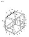
- Figure 1 is a perspective view showing a frame structure of an operator's cab installed in a work vehicle according to an embodiment of the invention.
- Figure 2 is a perspective view showing a main framework forming member which constitutes a side face of a cab's frame.
- Figure 3 is an enlarged sectional view taken along line A-A of Figure 2.
- Figure 4(a) is an enlarged sectional view taken along line B-B of Figure 2 and
- Figure 4(b) is an enlarged sectional view of a modification of the member shown in Figure 4(a).
- Figures 5(a), 5(b) show enlarged sectional views of a middle supporting column.
- the operator' s cab structure of the present embodiment is applied to a hydraulic excavator that is a typical construction machine.
- a frame 1 constituting the operator's cab of this embodiment is formed by assembling pipe members.
- a left (right) side member 2 (3) which is composed of a front supporting column 2a (3a), a longitudinal part 2b (3b) (hereinafter referred to as “ceiling longitudinal part 2b (3b)) at the ceiling section, and a rear supporting column 2c (3c), is formed by a single member which is bent into a shape having a desired size and desired profile.
- the left and right side members 2, 3 thus formed are connected to each other by means of a plurality of transverse connecting members 4, 4', 5, 5' , 5" of specified size, and the lower ends of each side member 2(3) are connected by a longitudinal member 6, whereby the contour of the cab is formed.
- the positional terms used herein (“right”, “left”, “longitudinal” and “transverse”) are based on the orientations when the operator's cab is viewed from a front window 7.
- the side members 2, 3 which constitute the left and right sides of the cab are respectively formed using a pipe member of modified cross-section as a main component as shown in Figures 2 and 3. Note that since the members 2, 3 are symmetrical, only one side member 2 will be described herein for simplicity.
- the pipe member is positioned such that its curved portion 2d corresponds to the ridge line of the operator' s cab, and a member 10 (hereinafter referred to as "guide rail") for forming a guide rail for the front window 7 is welded to an inwardly facing, flat side face portion 2e, extending in the region from the front supporting column 2a to the ceiling longitudinal part 2b.
- a small-sized pipe member 14 of rectangular cross-section is welded to the inwardly facing flat side face portion 2e within the rear supporting column portion 2c of the side member 2 such that the pipe member 14 is set back a specified length from an outer corner portion 2f which leads to the curved portion 2d of the main member, whereby a stepped portion 15 is formed.
- the main member (side member 2), the guide rail 10 and the pipe member 14 of rectangular cross-section are intermittently welded, thereby restricting generation of strains.
- the guide rail 10 attached to the side member 2 has an E-shaped cross-sectional structure defined by (i) a guide groove 11 for a guide roller 7a which is provided for the front window 7 and (ii) a seal contact portion 12 which is formed in parallel with the guide groove 11 and with which a sealing member 7b attached to the front window 7 comes into contact, thereby exerting a sealing function.
- the way of producing the guide rail 10 may be selected from (i) forming of a thin pipe material, (ii) forming of a sheet-like material (not shown), and (iii) rolling of a sheet-like material (not shown), as far as the function described above can be obtained.
- the small-sized pipe member 14 of rectangular cross-section attached to the rear supporting column 2c of the side member 2 may be replaced with a pipe member 14' having a ⁇ -shaped (channel-shaped) cross-section such as shown in Figure 4(b).
- the set-back length defining the stepped portion 15 is determined such that the glass 20 of the rear window can be fitted in the space of the stepped portion 15.
- the window glass to be fitted in this space is bonded to the pipe member 14 or 14'.
- a side glass (not shown) is bonded to the side member 2 at an outwardly facing stepped portion 2g.
- the left and right side members 2, 3 having the above-described cross-sectional structure are symmetrically disposed with a specified spacing between and with their curved portions 2d facing outward.
- the side members 2, 3 are integrally connected by the transverse connecting members 4, 4' ; 5, 5' ; 5" at the upper and lower parts of the front supporting columns 2a, 3a and the rear supporting columns 2c, 3c.
- Disposed at the middle position of the right side member 3 having an entrance 8 is a middle supporting column 9 both ends of which are connected to the ceiling longitudinal part 3b of the right side member 3 and the bottom longitudinal member 6 respectively.
- the middle supporting column 9 has, at one side, a sealing face 9a with which the door (not shown) is brought into sealing contact when it is closed.
- a small-sized pipe member 14 of rectangular cross-section is welded in the same fashion as in the rear supporting column 3c, so that a window glass 21 for the rear side section can be mounted on the pipe member 14.
- a doorstop member is attached to a flat surface of the front supporting column 3a of the right side member 3, the flat surface being positioned on the side of the entrance 8.
- the stepped portion (corresponding to the stepped portion 2g of the left side member 2) of the right side member 3 may be formed as a doorstop face.
- square and rectangular pipe members as shown in Figure 5(b) may be used for forming the middle supporting column 9.
- a small-sized pipe member of square cross-section 14 is welded to a square pipe member such that the window glass 21 can be mounted at a side face of the square pipe member, whereas a rectangular pipe member 14' is welded to the other side of the square pipe member for forming the sealing face 9a with which the door is brought into sealing contact when it is closed.
- the front supporting column 2a and rear supporting column 2c of the left side member 2 are connected, at their lower parts, by a window frame member 17 for supporting the lower edge of a side window, whereby the side window can be mounted.
- the middle supporting column 9 and the rear supporting column 3c of the right side member 3 are connected, at their middle parts, by a window frame member 18, whereby a rear side window can be mounted.
- the left and right side members 2, 3, which constitute the main part of the frame 1, are respectively formed by bending a single pipe member of modified cross-section into a desired shape and integrally attaching a functional member (the guide rail 10, a window frame (the small-sized pipe member 14) etc. ) to one side face of the pipe member.
- These side members 2, 3 are connected to each other by the transverse connecting members 4, 4' , 5, 5' , 5" at a plurality of positions which are spaced at desired intervals. Therefore, proper selection of shapes for the modified cross-sections of the pipe members and the attachment of the functional members make it possible to reduce the weight of the frame 1 while increasing the strength of the whole frame 1.
- the side members 2, 3 are precisely produced by eliminating bending strains, these members 2, 3 can be used as the basis for assembling the transverse connecting members 4 to 5", so that the manufacturing process can be rationalized and equipment investment can be saved, leading to significant cost reduction, since there is no need to use a large-sized jig such as conventionally required.
- rear supporting columns 2c', 3c' which are formed from members different from those of the front supporting columns 2a, 3a and the ceiling longitudinal parts 2b, 3b
- This embodiment is the same as the foregoing embodiment except that the rear supporting columns 2c' , 3c' are formed from different members).
- This arrangement differs from the foregoing embodiment in that the ceiling longitudinal parts 2b, 3b are connected, by welding, to the rear supporting columns 2c' , 3c' respectively to form the side members 2, 3, but has the same effects as those of the foregoing embodiment, that is, a weight reduction in the frame 1 and an increase in the strength of the whole frame 1.
Applications Claiming Priority (2)
| Application Number | Priority Date | Filing Date | Title |
|---|---|---|---|
| JP2002255003 | 2002-08-30 | ||
| JP2002255003 | 2002-08-30 |
Publications (2)
| Publication Number | Publication Date |
|---|---|
| EP1394019A1 true EP1394019A1 (de) | 2004-03-03 |
| EP1394019B1 EP1394019B1 (de) | 2008-12-10 |
Family
ID=31492668
Family Applications (1)
| Application Number | Title | Priority Date | Filing Date |
|---|---|---|---|
| EP03019764A Expired - Fee Related EP1394019B1 (de) | 2002-08-30 | 2003-08-29 | Fahrerhausrahmen |
Country Status (4)
| Country | Link |
|---|---|
| EP (1) | EP1394019B1 (de) |
| KR (1) | KR20040019843A (de) |
| CN (1) | CN100333957C (de) |
| DE (1) | DE60325146D1 (de) |
Cited By (4)
| Publication number | Priority date | Publication date | Assignee | Title |
|---|---|---|---|---|
| EP1752585A2 (de) * | 2005-08-12 | 2007-02-14 | Kobleco Construction Machinery Co., Ltd. | Baumaschine |
| EP1707478A3 (de) * | 2005-03-31 | 2007-08-15 | Kabushiki Kaisha Toyota Jidoshokki | Fahrerschutzdach für Industriefahrzeug |
| EP3333119A1 (de) * | 2016-12-08 | 2018-06-13 | STILL GmbH | Flurförderzeug mit einem fahrerschutzdach |
| US11479944B2 (en) | 2018-07-31 | 2022-10-25 | Komatsu Ltd. | Work machine and cab |
Families Citing this family (8)
| Publication number | Priority date | Publication date | Assignee | Title |
|---|---|---|---|---|
| KR100861561B1 (ko) * | 2006-11-08 | 2008-10-02 | 볼보 컨스트럭션 이키프먼트 홀딩 스웨덴 에이비 | 중장비용 운전실 |
| CN102442359A (zh) * | 2010-09-30 | 2012-05-09 | 扬州神舟汽车内饰件有限公司 | 一种具有前翻窗的工程车驾驶室 |
| CN102653286A (zh) * | 2011-03-04 | 2012-09-05 | 柳工常州挖掘机有限公司 | 具有rops保护结构的工程机械驾驶室 |
| US20140017053A1 (en) * | 2011-06-13 | 2014-01-16 | Hitachi Construction Machinery Co., Ltd. | Construction machine |
| CN102720238A (zh) * | 2012-06-07 | 2012-10-10 | 三一重机有限公司 | 工程机械、工程机械用驾驶室及驾驶室框架结构 |
| CN106515877A (zh) * | 2016-12-27 | 2017-03-22 | 潍坊盛瑞零部件有限公司 | 一种农机用驾驶室 |
| CN109623273B (zh) * | 2018-12-14 | 2020-02-25 | 柳工常州机械有限公司 | 驾驶室骨架及制造方法 |
| CN110886339A (zh) * | 2019-12-13 | 2020-03-17 | 江苏徐工工程机械研究院有限公司 | 一种驾驶室骨架、驾驶室及挖掘机 |
Citations (6)
| Publication number | Priority date | Publication date | Assignee | Title |
|---|---|---|---|---|
| CH506404A (fr) * | 1969-04-28 | 1971-04-30 | Tech Et Modeles Ind C O Me Gum | Carrosserie de véhicule |
| GB2099377A (en) * | 1981-03-25 | 1982-12-08 | Artweger Ind | Improvements in detachable hard-tops for vehicles |
| DE29608575U1 (de) * | 1996-05-13 | 1996-08-14 | Schneider Fahrkomfort Gmbh | Fahrerkabine für Gabelstapler oder Baumaschinen |
| JPH10291485A (ja) * | 1997-04-21 | 1998-11-04 | Mitsubishi Agricult Mach Co Ltd | 作業機のキャビン |
| JP2001171992A (ja) * | 1999-12-20 | 2001-06-26 | Toyota Autom Loom Works Ltd | 産業車両のヘッドガード及びフォークリフト |
| JP2002249073A (ja) * | 2001-02-27 | 2002-09-03 | Kubota Corp | 作業車キャビンの天井構造 |
Family Cites Families (5)
| Publication number | Priority date | Publication date | Assignee | Title |
|---|---|---|---|---|
| JP3829056B2 (ja) * | 1998-10-31 | 2006-10-04 | プレス工業株式会社 | 建設機械用キャブ |
| JP2000198469A (ja) * | 1998-10-31 | 2000-07-18 | Press Kogyo Co Ltd | 鋳物製継手を用いた建設機械用キャブ |
| JP2000313364A (ja) * | 1999-04-30 | 2000-11-14 | Komatsu Ltd | 作業車両の運転室 |
| JP2001081811A (ja) * | 1999-09-14 | 2001-03-27 | Komatsu Ltd | 建設機械用キャブ |
| KR100418073B1 (ko) * | 2000-09-18 | 2004-02-14 | 프레스 고교 가부시기가이샤 | 건설기계용 캐브 |
-
2003
- 2003-02-18 KR KR1020030009994A patent/KR20040019843A/ko not_active Application Discontinuation
- 2003-08-29 DE DE60325146T patent/DE60325146D1/de not_active Expired - Lifetime
- 2003-08-29 EP EP03019764A patent/EP1394019B1/de not_active Expired - Fee Related
- 2003-09-01 CN CNB031557376A patent/CN100333957C/zh not_active Expired - Fee Related
Patent Citations (6)
| Publication number | Priority date | Publication date | Assignee | Title |
|---|---|---|---|---|
| CH506404A (fr) * | 1969-04-28 | 1971-04-30 | Tech Et Modeles Ind C O Me Gum | Carrosserie de véhicule |
| GB2099377A (en) * | 1981-03-25 | 1982-12-08 | Artweger Ind | Improvements in detachable hard-tops for vehicles |
| DE29608575U1 (de) * | 1996-05-13 | 1996-08-14 | Schneider Fahrkomfort Gmbh | Fahrerkabine für Gabelstapler oder Baumaschinen |
| JPH10291485A (ja) * | 1997-04-21 | 1998-11-04 | Mitsubishi Agricult Mach Co Ltd | 作業機のキャビン |
| JP2001171992A (ja) * | 1999-12-20 | 2001-06-26 | Toyota Autom Loom Works Ltd | 産業車両のヘッドガード及びフォークリフト |
| JP2002249073A (ja) * | 2001-02-27 | 2002-09-03 | Kubota Corp | 作業車キャビンの天井構造 |
Non-Patent Citations (3)
| Title |
|---|
| PATENT ABSTRACTS OF JAPAN vol. 1999, no. 02 26 February 1999 (1999-02-26) * |
| PATENT ABSTRACTS OF JAPAN vol. 2000, no. 23 10 February 2001 (2001-02-10) * |
| PATENT ABSTRACTS OF JAPAN vol. 2003, no. 01 14 January 2003 (2003-01-14) * |
Cited By (7)
| Publication number | Priority date | Publication date | Assignee | Title |
|---|---|---|---|---|
| EP1707478A3 (de) * | 2005-03-31 | 2007-08-15 | Kabushiki Kaisha Toyota Jidoshokki | Fahrerschutzdach für Industriefahrzeug |
| US7472945B2 (en) | 2005-03-31 | 2009-01-06 | Kabushiki Kaisha Toyota Jidoshokki | Overhead guard of industrial vehicle |
| CN100591609C (zh) * | 2005-03-31 | 2010-02-24 | 株式会社丰田自动织机 | 工业用车辆的顶置护板 |
| EP1752585A2 (de) * | 2005-08-12 | 2007-02-14 | Kobleco Construction Machinery Co., Ltd. | Baumaschine |
| EP1752585A3 (de) * | 2005-08-12 | 2014-03-26 | Kobelco Construction Machinery Co., Ltd. | Baumaschine |
| EP3333119A1 (de) * | 2016-12-08 | 2018-06-13 | STILL GmbH | Flurförderzeug mit einem fahrerschutzdach |
| US11479944B2 (en) | 2018-07-31 | 2022-10-25 | Komatsu Ltd. | Work machine and cab |
Also Published As
| Publication number | Publication date |
|---|---|
| DE60325146D1 (de) | 2009-01-22 |
| KR20040019843A (ko) | 2004-03-06 |
| EP1394019B1 (de) | 2008-12-10 |
| CN1486901A (zh) | 2004-04-07 |
| CN100333957C (zh) | 2007-08-29 |
Similar Documents
| Publication | Publication Date | Title |
|---|---|---|
| JP3474417B2 (ja) | 建設機械の運転室 | |
| EP1394019B1 (de) | Fahrerhausrahmen | |
| EP1666343B1 (de) | Kabine von baumaschine | |
| US20040104060A1 (en) | Driver's cab for a work vehicle | |
| US8267467B2 (en) | Reinforcement for cab in construction machine | |
| EP1630079B1 (de) | Fahrerkabine eines Arbeitsfahrzeugs | |
| KR101509783B1 (ko) | 자동차의 도어 구조 | |
| US8668249B2 (en) | Frame for a cab of a mobile machine | |
| CN102720238A (zh) | 工程机械、工程机械用驾驶室及驾驶室框架结构 | |
| JP2004106824A (ja) | 作業車両の運転室構造 | |
| JP3572373B2 (ja) | センターピラーの補強構造 | |
| JP4029632B2 (ja) | 建設機械のキャビン構造 | |
| CN110315939B (zh) | 前门 | |
| JP2007069776A (ja) | キャブ用補強部材、キャブおよび作業機械 | |
| JP4553515B2 (ja) | 作業車両のキャブ構造 | |
| JP4484546B2 (ja) | 作業機械の運転室構造 | |
| JP3997187B2 (ja) | 自動車のベルトライン部構造 | |
| JPS63227439A (ja) | 自動車用側張り縁部 | |
| JP2007099236A (ja) | キャブおよび作業機械 | |
| US20240116336A1 (en) | Vehicle door structure | |
| JP2002088812A (ja) | 建設機械用キャブ | |
| CN220374254U (zh) | 天窗加强框以及车辆 | |
| JP2009061858A (ja) | 自動車のセンターピラー構造 | |
| CN112124053A (zh) | 车辆用门 | |
| KR20190122480A (ko) | 웨더스트립용 심금 |
Legal Events
| Date | Code | Title | Description |
|---|---|---|---|
| PUAI | Public reference made under article 153(3) epc to a published international application that has entered the european phase |
Free format text: ORIGINAL CODE: 0009012 |
|
| AK | Designated contracting states |
Kind code of ref document: A1 Designated state(s): AT BE BG CH CY CZ DE DK EE ES FI FR GB GR HU IE IT LI LU MC NL PT RO SE SI SK TR |
|
| AX | Request for extension of the european patent |
Extension state: AL LT LV MK |
|
| 17P | Request for examination filed |
Effective date: 20040401 |
|
| AKX | Designation fees paid |
Designated state(s): DE GB IT |
|
| 17Q | First examination report despatched |
Effective date: 20060127 |
|
| GRAP | Despatch of communication of intention to grant a patent |
Free format text: ORIGINAL CODE: EPIDOSNIGR1 |
|
| GRAS | Grant fee paid |
Free format text: ORIGINAL CODE: EPIDOSNIGR3 |
|
| GRAA | (expected) grant |
Free format text: ORIGINAL CODE: 0009210 |
|
| AK | Designated contracting states |
Kind code of ref document: B1 Designated state(s): DE GB IT |
|
| REG | Reference to a national code |
Ref country code: GB Ref legal event code: FG4D |
|
| REF | Corresponds to: |
Ref document number: 60325146 Country of ref document: DE Date of ref document: 20090122 Kind code of ref document: P |
|
| PLBE | No opposition filed within time limit |
Free format text: ORIGINAL CODE: 0009261 |
|
| STAA | Information on the status of an ep patent application or granted ep patent |
Free format text: STATUS: NO OPPOSITION FILED WITHIN TIME LIMIT |
|
| 26N | No opposition filed |
Effective date: 20090911 |
|
| PGFP | Annual fee paid to national office [announced via postgrant information from national office to epo] |
Ref country code: GB Payment date: 20120829 Year of fee payment: 10 |
|
| PGFP | Annual fee paid to national office [announced via postgrant information from national office to epo] |
Ref country code: IT Payment date: 20120813 Year of fee payment: 10 |
|
| GBPC | Gb: european patent ceased through non-payment of renewal fee |
Effective date: 20130829 |
|
| PG25 | Lapsed in a contracting state [announced via postgrant information from national office to epo] |
Ref country code: IT Free format text: LAPSE BECAUSE OF NON-PAYMENT OF DUE FEES Effective date: 20130829 |
|
| PG25 | Lapsed in a contracting state [announced via postgrant information from national office to epo] |
Ref country code: GB Free format text: LAPSE BECAUSE OF NON-PAYMENT OF DUE FEES Effective date: 20130829 |
|
| PGFP | Annual fee paid to national office [announced via postgrant information from national office to epo] |
Ref country code: DE Payment date: 20140827 Year of fee payment: 12 |
|
| REG | Reference to a national code |
Ref country code: DE Ref legal event code: R119 Ref document number: 60325146 Country of ref document: DE |
|
| PG25 | Lapsed in a contracting state [announced via postgrant information from national office to epo] |
Ref country code: DE Free format text: LAPSE BECAUSE OF NON-PAYMENT OF DUE FEES Effective date: 20160301 |