EP1387137B1 - Vorrichtung zur Bandbegichtung eines Hochofens - Google Patents
Vorrichtung zur Bandbegichtung eines Hochofens Download PDFInfo
- Publication number
- EP1387137B1 EP1387137B1 EP03017130A EP03017130A EP1387137B1 EP 1387137 B1 EP1387137 B1 EP 1387137B1 EP 03017130 A EP03017130 A EP 03017130A EP 03017130 A EP03017130 A EP 03017130A EP 1387137 B1 EP1387137 B1 EP 1387137B1
- Authority
- EP
- European Patent Office
- Prior art keywords
- rotary distributor
- bell
- axis
- rotation
- blast furnace
- Prior art date
- Legal status (The legal status is an assumption and is not a legal conclusion. Google has not performed a legal analysis and makes no representation as to the accuracy of the status listed.)
- Revoked
Links
- 239000000463 material Substances 0.000 claims abstract description 25
- 230000005484 gravity Effects 0.000 claims abstract 2
- 239000000872 buffer Substances 0.000 claims description 24
- 239000000571 coke Substances 0.000 claims description 4
- 239000003638 chemical reducing agent Substances 0.000 claims description 3
- 239000013590 bulk material Substances 0.000 claims description 2
- 241000273930 Brevoortia tyrannus Species 0.000 description 33
- 201000005569 Gout Diseases 0.000 description 20
- 239000007858 starting material Substances 0.000 description 9
- 239000007789 gas Substances 0.000 description 5
- 206010053648 Vascular occlusion Diseases 0.000 description 4
- 238000013461 design Methods 0.000 description 3
- 241001136792 Alle Species 0.000 description 2
- 238000010276 construction Methods 0.000 description 2
- 238000006073 displacement reaction Methods 0.000 description 2
- 238000004519 manufacturing process Methods 0.000 description 2
- 244000257782 Ipomoea triloba Species 0.000 description 1
- 229910000805 Pig iron Inorganic materials 0.000 description 1
- 238000009825 accumulation Methods 0.000 description 1
- 230000015572 biosynthetic process Effects 0.000 description 1
- 230000000694 effects Effects 0.000 description 1
- 230000007613 environmental effect Effects 0.000 description 1
- 238000002474 experimental method Methods 0.000 description 1
- 238000000265 homogenisation Methods 0.000 description 1
- 238000000034 method Methods 0.000 description 1
- 238000012986 modification Methods 0.000 description 1
- 230000004048 modification Effects 0.000 description 1
- 229920001296 polysiloxane Polymers 0.000 description 1
- 230000000717 retained effect Effects 0.000 description 1
- 230000000630 rising effect Effects 0.000 description 1
- 238000007789 sealing Methods 0.000 description 1
- 238000000926 separation method Methods 0.000 description 1
- 239000013589 supplement Substances 0.000 description 1
- 238000012549 training Methods 0.000 description 1
Images

Classifications
-
- C—CHEMISTRY; METALLURGY
- C21—METALLURGY OF IRON
- C21B—MANUFACTURE OF IRON OR STEEL
- C21B7/00—Blast furnaces
- C21B7/18—Bell-and-hopper arrangements
- C21B7/20—Bell-and-hopper arrangements with appliances for distributing the burden
-
- F—MECHANICAL ENGINEERING; LIGHTING; HEATING; WEAPONS; BLASTING
- F27—FURNACES; KILNS; OVENS; RETORTS
- F27D—DETAILS OR ACCESSORIES OF FURNACES, KILNS, OVENS OR RETORTS, IN SO FAR AS THEY ARE OF KINDS OCCURRING IN MORE THAN ONE KIND OF FURNACE
- F27D3/00—Charging; Discharging; Manipulation of charge
- F27D3/0025—Charging or loading melting furnaces with material in the solid state
- F27D3/0032—Charging or loading melting furnaces with material in the solid state using an air-lock
-
- F—MECHANICAL ENGINEERING; LIGHTING; HEATING; WEAPONS; BLASTING
- F27—FURNACES; KILNS; OVENS; RETORTS
- F27D—DETAILS OR ACCESSORIES OF FURNACES, KILNS, OVENS OR RETORTS, IN SO FAR AS THEY ARE OF KINDS OCCURRING IN MORE THAN ONE KIND OF FURNACE
- F27D3/00—Charging; Discharging; Manipulation of charge
- F27D3/10—Charging directly from hoppers or shoots
-
- F—MECHANICAL ENGINEERING; LIGHTING; HEATING; WEAPONS; BLASTING
- F27—FURNACES; KILNS; OVENS; RETORTS
- F27B—FURNACES, KILNS, OVENS OR RETORTS IN GENERAL; OPEN SINTERING OR LIKE APPARATUS
- F27B1/00—Shaft or like vertical or substantially vertical furnaces
- F27B1/10—Details, accessories or equipment specially adapted for furnaces of these types
- F27B1/20—Arrangements of devices for charging
-
- F—MECHANICAL ENGINEERING; LIGHTING; HEATING; WEAPONS; BLASTING
- F27—FURNACES; KILNS; OVENS; RETORTS
- F27D—DETAILS OR ACCESSORIES OF FURNACES, KILNS, OVENS OR RETORTS, IN SO FAR AS THEY ARE OF KINDS OCCURRING IN MORE THAN ONE KIND OF FURNACE
- F27D3/00—Charging; Discharging; Manipulation of charge
- F27D2003/0034—Means for moving, conveying, transporting the charge in the furnace or in the charging facilities
- F27D2003/0063—Means for moving, conveying, transporting the charge in the furnace or in the charging facilities comprising endless belts
-
- F—MECHANICAL ENGINEERING; LIGHTING; HEATING; WEAPONS; BLASTING
- F27—FURNACES; KILNS; OVENS; RETORTS
- F27D—DETAILS OR ACCESSORIES OF FURNACES, KILNS, OVENS OR RETORTS, IN SO FAR AS THEY ARE OF KINDS OCCURRING IN MORE THAN ONE KIND OF FURNACE
- F27D3/00—Charging; Discharging; Manipulation of charge
- F27D2003/0085—Movement of the container or support of the charge in the furnace or in the charging facilities
- F27D2003/0087—Rotation about a vertical axis
-
- F—MECHANICAL ENGINEERING; LIGHTING; HEATING; WEAPONS; BLASTING
- F27—FURNACES; KILNS; OVENS; RETORTS
- F27D—DETAILS OR ACCESSORIES OF FURNACES, KILNS, OVENS OR RETORTS, IN SO FAR AS THEY ARE OF KINDS OCCURRING IN MORE THAN ONE KIND OF FURNACE
- F27D3/00—Charging; Discharging; Manipulation of charge
- F27D3/0033—Charging; Discharging; Manipulation of charge charging of particulate material
-
- F—MECHANICAL ENGINEERING; LIGHTING; HEATING; WEAPONS; BLASTING
- F27—FURNACES; KILNS; OVENS; RETORTS
- F27M—INDEXING SCHEME RELATING TO ASPECTS OF THE CHARGES OR FURNACES, KILNS, OVENS OR RETORTS
- F27M2001/00—Composition, conformation or state of the charge
- F27M2001/02—Charges containing ferrous elements
- F27M2001/023—Ferrites
-
- F—MECHANICAL ENGINEERING; LIGHTING; HEATING; WEAPONS; BLASTING
- F27—FURNACES; KILNS; OVENS; RETORTS
- F27M—INDEXING SCHEME RELATING TO ASPECTS OF THE CHARGES OR FURNACES, KILNS, OVENS OR RETORTS
- F27M2001/00—Composition, conformation or state of the charge
- F27M2001/03—Charges containing minerals
-
- F—MECHANICAL ENGINEERING; LIGHTING; HEATING; WEAPONS; BLASTING
- F27—FURNACES; KILNS; OVENS; RETORTS
- F27M—INDEXING SCHEME RELATING TO ASPECTS OF THE CHARGES OR FURNACES, KILNS, OVENS OR RETORTS
- F27M2001/00—Composition, conformation or state of the charge
- F27M2001/04—Carbon-containing material
- F27M2001/045—Coke
-
- F—MECHANICAL ENGINEERING; LIGHTING; HEATING; WEAPONS; BLASTING
- F27—FURNACES; KILNS; OVENS; RETORTS
- F27M—INDEXING SCHEME RELATING TO ASPECTS OF THE CHARGES OR FURNACES, KILNS, OVENS OR RETORTS
- F27M2003/00—Type of treatment of the charge
- F27M2003/16—Treatment involving a chemical reaction
- F27M2003/165—Reduction
Definitions
- the invention relates to a device for Bandbegichtung a operated with an increased back pressure blast furnace, with a conveyor belt for the continuous supply of Möller, aggregates and predominantly coke as a reducing agent feedstocks for bell-gout closure of the blast furnace and with feeders above and within the Bell Gout closure for the task and material distribution of the starting materials on the one above the other in a buffer bunker arranged bells of different sizes.
- the blast furnace feedstock accounts for 2.0 to 2.5 times the weight of pig iron production. Characteristics of the here required unloading, bunker, feeder and Be slaughterungsanlagen are therefore high performance with the greatest possible mechanization.
- means of delivery are understood to mean transport devices which transport the starting materials to the upper end of the blast furnace for the Gicht catch arranged there.
- Known transport devices are Riebelbegichtung (bucket or tilt bucket (SKIP)) with inclined elevator or Bandbegichtung with a revolving conveyor belt, which is designed as inclined or vertical conveyor.
- SKIP tilt bucket
- Bandbegichtung is for example in the DE 198 24 367 A1 described.
- the feeds are dumped at the upper end of the Gessver gleiches in an upper funnel, which is closed at the bottom by an upper small bell.
- an upper small bell By lowering the small bell that falls filled material into a large hopper located below, which is closed by a lower large bell.
- the treatment greatly influences the processes taking place in the blast furnace.
- the feedstock consisting of coarse material and fine material is distributed over the furnace cross-section, because the fines offer a considerably greater resistance to rising gases.
- greasing the material slips over sloping surfaces The result is a pouring ring of conical cross-section, with a separation takes place: coarse material is then outside and the fines inside.
- the Japanese Patent Laid-Open Publication No. 02 011 711 describes a different device for banding a blast furnace, with a conveyor belt for the continuous supply of feedstocks (Möller, supplements and predominantly coke as a reducing agent) to a bell-gout closure of the blast furnace.
- feeding devices are provided above and within the bell-gout closure for the task and material distribution of the starting materials, inter alia, on a bell arranged in a buffer bunker.
- the internal bell-gating closure bell is comprised of an inclined, pivotable chute whose pivot axis is coaxial with the vertical axis of the buffer bunker and the bell.
- the obliquely arranged chute causes at the outlet of the chute an outward directed towards the bunker wall material flow.
- the internal feeding device for the small bell of the bell-gout closure is a arranged below a stationary task chute funnel-shaped rotary distributor, coaxial with the vertical axis of the circular buffer bunker and the vertical axis the small bell arranged rotational axis and with a to its axis of rotation and the centroid of its Ein spallqueritess laterally offset vertical outlet opening.
- the optimal distribution of material on the small bell by the inventive design of the inner feeder in the form of a rotary distributor allows to use this rotary distributor with its advantages in terms of gas seal even with blast furnaces with band coverage. This provides the opportunity to increase the gout pressure and to reduce coke consumption and increase production efficiency through more efficient gas utilization.
- This optimal material distribution is achieved by the offset to the axis of rotation laterally offset outlet opening of the rotary distributor, whereby the starting materials in the rotation of the rotary distributor uniformly over the entire cross section of the Puffer bunker and thus be distributed over the small bell.
- the outlet opening is as far as offset laterally to its axis of rotation that it is located approximately on the seat diameter of the small bell.
- This Schüttgutböschung not only provides a simple and effective wear protection of the side walls of the rotary distributor, but also favors due to the frictional conditions brought about by them a largely homogeneous discharge of the starting materials in their discharge through the oblique side walls of the rotary distributor down into the buffer bunker.
- the bulk material embankment can also build on the different oblique side walls with a uniform layer height, the projecting into the rotary distributor outlet part on the opposite side of the flatter side wall of the rotary distributor side is still extended with a half-shell pipe part.
- the accumulation effect is increased at the steeper side walls and thus made uniform the layer height of Schüttgutböschung over the entire circumference of the rotary distributor.
- the rotary distributor is geometrically designed so that it is always located at any rotational position with its filling cross section below the outlet opening of the above the rotary distributor arranged stationary task chute or one of these downstream hopper. It follows that in the case of a round filling cross section, the opening radius of the filling cross section and, correspondingly, in the case of a square filling cross section, the distance of its outer edge from its axis of rotation corresponds at least to the distance between this filling outlet opening and the vertical axis of the circular buffer bunker.
- the arranged below the fixed task bunk rotary distributor is supported on the inside of the bunker wall rotating guide rollers and a guide on the central tube of the GichtverInstitutes horizontal, while the vertical support is realized on the bunker cover.
- the rotary distributor is driven by means of suitable drive devices which are operatively connected to the rotary distributor on the circumference and / or on the axis thereof.
- suitable drive devices which are operatively connected to the rotary distributor on the circumference and / or on the axis thereof.
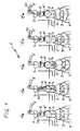
- FIG. 1 a is the function of the rotary distributor according to the invention in a similar manner as in Fig. 1 shown.
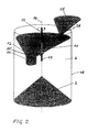
- FIG. 2 these construction parts involved here are once again shown schematically.
- a round rotary distributor 10 within the circular buffer bunker 6 with a lower bell 2 arranged at the bottom there is a round rotary distributor 10 according to the invention at a distance from the small bell 2, the axis of rotation 15 of which coincides coaxially with the bunker axis 16 of the round buffer bunker 6. Laterally offset to its axis of rotation 15 and the centroid 14 of the filling cross section 13 (see Fig. 3 ) is located in the rotary distributor 10, a vertical outlet opening 11 ', which is extended downwardly and inwardly by an outlet pipe 11.
- This lateral displacement of the outlet opening 11 'causes the feedstocks 30 are distributed in a desired manner homogeneously and evenly on the small bell 2 and within the buffer bunker 6 to its side walls 18 in dependence on the rotational speed of the rotary distributor 10 and the discharge speed of the feedstock 30 ,
- the discharge speed is determined by the friction conditions on the oblique side walls of the rotary distributor 10 and the inclination.
- the horizontal support of the rotary distributor 10 on the central tube of the bell-gout closure 1 is shown schematically by a guide 17.
- the remaining horizontal and vertical supports and the drive device of the rotary distributor 10 are not shown.
- anismschurre 25 with an outlet opening 26 which can be closed by a shut-off (the obturator is not shown).
- the rotational axis 15 and the filling cross section 13 of the rotary distributor 10 are arranged or formed so that at each rotational position of the rotary distributor 10, a part of the Ein spallqueritess 13 is below the outlet opening 26, so that no material on the rotary distributor 10 passes over into the buffer bunker 6.
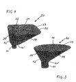
- FIGS. 3 and 4 Possible embodiments of a rotary distributor according to the invention are shown schematically in an individual representation.
- the in Fig. 3 shown rotary distributor 10 of Fig. 2 has a round filling cross section 13 and a lower round outlet opening 11 '.
- the outlet opening 11 ' is extended downwardly and inwardly by an outlet pipe 11.
- the extension of the outlet pipe 11 inwardly causes the feedstock 30 in the gusset formed from the oblique side walls 19, 19 'and the inwardly projecting spout part dehumidify the starting materials 30 (the starting materials are not shown) and on the oblique side walls 19 a Train bulkhead slope.
- FIG. 4 is shown as another possible training variant a square rotary distributor 20.
- the outlet opening 11 ' is laterally offset relative to the centroid 24 of the Ein Schollqueritess 23, so that also different oblique side walls 29, 29' result.
- the outlet pipe 11 is also extended inwardly with a half-shell pipe part 12 on the steep side wall 29 'in the angular rotary distributor 20.
- the axis of rotation of this angular rotary distributor 10 (the axis of rotation is not shown) runs so that the side edges 22 of the different oblique side walls 29, 29 'are always below the outlet opening of a arranged above the rotary distributor 10 bunker or hopper, so that no material on Rotary distributor 10 can fall over on the small bell 2.
- the axis of rotation need not necessarily be guided by the centroid 24 of the Ein spallqueritess 23.
- the invention is not limited to the illustrated embodiments, but variable in terms of geometry and design of the rotary distributor and its arrangement above the small bell to prevailing conditions customizable.
Landscapes
- Engineering & Computer Science (AREA)
- Mechanical Engineering (AREA)
- General Engineering & Computer Science (AREA)
- Chemical & Material Sciences (AREA)
- Manufacturing & Machinery (AREA)
- Materials Engineering (AREA)
- Metallurgy (AREA)
- Organic Chemistry (AREA)
- Blast Furnaces (AREA)
- Manufacture Of Iron (AREA)
Description
- Die Erfindung betrifft eine Vorrichtung zur Bandbegichtung eines mit einem erhöhten Gegendruck betriebenen Hochofens, mit einem Transportband zur kontinuierlichen Zuführung der aus Möller, Zuschlägen und vorwiegend Koks als Reduktionsmittel bestehenden Einsatzstoffe zum Glocken-Gicht-Verschluss des Hochofens und mit Aufgabevorrichtungen oberhalb und innerhalb des Glocken-Gicht-Verschlusses zur Aufgabe und Materialverteilung der Einsatzstoffe auf die übereinander in einem Pufferbunker angeordneten Glocken unterschiedlicher Größe.
- Die Hochofeneinsatzstoffe machen insgesamt das 2,0 - bis 2,5-fache Gewicht der Roheisenerzeugung aus. Kennzeichen der hier benötigten Entlade-, Bunker-, Zubringer- und Begichtungsanlagen sind daher hohe Leistung bei möglichst weitgehender Mechanisierung. Unter Begichtungsanlagen werden dabei Transportvorrichtungen verstanden, die die Einsatzstoffe zum oberen Ende des Hochofens zum dort angeordneten Gichtverschluss transportieren.
- Bekannte Transportvorrichtungen sind Kübelbegichtung (Senkkübel oder Kippkübel (Skip)) mit Schrägaufzug oder Bandbegichtung mit einem umlaufenden Transportband, das als Schräg- oder Senkrechtförderer ausgebildet ist. Eine derartige Bandbegichtung wird beispielsweise in der
DE 198 24 367 A1 beschrieben. - Mit den Transportvorrichtungen werden die Einsatzstoffe am oberen Ende des Gichtverschlusses in einen oberen Trichter abgekippt, der unten durch eine obere kleine Glocke abgeschlossen ist. Durch Absenkung der kleinen Glocke fällt das eingefüllte Material in einen darunter angeordneten großen Trichter, der durch eine untere große Glocke abgeschlossen ist.
- Die Begichtung beeinflusst die im Hochofen ablaufenden Vorgänge stark. Entscheidend ist dabei in erster Linie, wie die aus Grobgut und Feingut bestehenden Einsatzstoffe auf den Ofenquerschnitt verteilt werden, denn das Feingut bietet aufsteigenden Gasen einen erheblich größeren Widerstand. Beim Gichten rutscht das Material über schräge Flächen ab; es entsteht ein Schüttring von kegeligem Querschnitt, wobei eine Entmischung stattfindet: Grobgut befindet sich dann außen und das Feingut innen.
- Bedingt durch die gestiegenen Umweltschutzanforderungen und die Notwendigkeit, den Ofen bei optimalen Betriebsbedingungen, wie einem erhöhten Gegendruck zu betreiben, ist eine Modifizierung vieler existierender Gichtverschlüsse erforderlich. In den meisten Fällen wird dies durch den Einbau von Dichtklappen im Materialaufgabebereich und Silikondichtringen an der kleinen Glocke, bzw. am Sitzring, sowie die Ausrüstung mit einem Druckausgleichsystem erreicht. Die sich dabei ergebende Problematik ist die gleichmäßige Verteilung der Einsatzstoffe auf der kleinen Glocke bzw. im Materialbunker. Die hierzu bisher eingesetzten Schichtverteiler stellten bei drucklosen Betrieb des Hochofens keine besonderen Anforderungen an die Gasabdichtung. Hauptprobleme des Gegendruckbetriebes und somit Kostenfaktoren sind die Abdichtungen der beweglichen Teile der Hochofengicht, insbesondere bei einer kontinuierlichen Materialzuführung über einen längeren Zeitraum bei einer Bandbegichtung, sowie der Verschleiß der mit den Einsatzstoffen in Kontakt stehenden schrägen Flächen wie beispielsweise die Glockensitzflächen.
- Eine ausführliche Beschreibung von Gichtverschlüssen für Hochleistungs-Hochöfen mit Gegendruckbetrieb ist dem Firmenprospekt: "Unser Partner ist die Welt -GHH-IHI-Gichtverschluss für Hochleistungs-Hochöfen mit Gegendruckbetrieb", Gutehoffnungshütte Sterkrade Aktiengesellschaft, 4200 Oberhausen-Sterkrade, Postfach 103, zu entnehmen.
- Die
Japanische Offenlegungsschrift Nr. 02 011 711 - Ausgehend von diesem bekannten Stand der Technik ist es Aufgabe der Erfindung, eine Vorrichtung zu schaffen, mit der die Probleme der Materialaufgabe und Materialverteilung bei der Begichtung eines Hochofens zumindest teilweise minimiert werden können.
- Die gestellte Aufgabe wird mit den kennzeichnenden Merkmalen des Anspruchs 1 dadurch gelöst, dass die innenliegende Aufgabevorrichtung für die kleine Glocke des Glocken-Gicht-Verschlusses ein unterhalb einer ortsfesten Aufgabeschurre angeordneter trichterförmiger Drehverteiler ist, mit koaxial zur vertikalen Achse des runden Pufferbunkers und zur vertikalen Achse der kleinen Glocke angeordneter Rotationsachse und mit einer zu seiner Rotationsachse und zum Flächenschwerpunkt seines Einfüllquerschnitts seitlich versetzten senkrechten Auslauföffnung.
- Vorteilhafte Ausgestaltungen der Erfindung sind in den Unteransprüchen angegeben.
- Die optimale Materialverteilung auf die kleine Glocke durch die erfindungsgemäße Ausbildung der innenliegenden Aufgabevorrichtung in Form eines Drehverteilers erlaubt es, auch bei Hochöfen mit Bandbegichtung diesen Drehverteiler mit seinen Vorteilen hinsichtlich der Gasabdichtung einzusetzen. Damit wird die Möglichkeit gegeben, den Gichtdruck anzuheben und durch eine effizientere Gasausnutzung den Koksverbrauch zu senken und die Produktionsleistung zu steigern.
- Diese optimale Materialverteilung wird dabei durch die zur Rotationsachse seitlich versetzte Auslauföffnung des Drehverteilers erreicht, wodurch die Einsatzstoffe bei der Rotation des Drehverteilers gleichmäßig über den gesamten Querschnitt des Pufferbunkers und damit auch über die kleine Glocke verteilt werden. Die Auslauföffnung ist dabei soweit seitlich zu ihrer Rotationsachse versetzt, dass sie sich etwa auf dem Sitzdurchmesser der kleinen Glocke befindet.
- Weiterhin wird durch die erfindungsgemäße Ausbildung des Drehverteilers mit einem die Auslauföffnung nach unten verlängernden senkrechten Auslaufrohr und mit dem Merkmal, dass das Auslaufrohr mit einer Teillänge in den trichterförmigen Drehverteiler hineinragt, erreicht, dass sich an diesem inneren Rohrstück die Einsatzstoffe aufstauen und sich auf den schrägen Wänden des Drehverteilers eine Schüttgutböschung aufbaut. Diese Schüttgutböschung stellt nicht nur einen einfachen und wirksamen Verschleißschutz der Seitenwände des Drehverteilers dar, sondern begünstigt auch auf Grund der durch sie herbeigeführten Reibungsverhältnisse einen weitgehend homogenen Austrag der Einsatzstoffe bei ihrem Austrag über die schrägen Seitenwände des Drehverteilers nach unten in den Pufferbunker.
- Damit sich die Schüttgutböschung auch auf den unterschiedlich schrägen Seitenwänden mit gleichmäßiger Schichthöhe aufbauen kann, ist der in den Drehverteiler hineinragende Auslaufrohrteil auf der der flacheren Seitenwand des Drehverteilers gegenüberliegenden Seite noch mit einem halbschaligen Rohrteil verlängert. Durch diese Maßnahme wird die Stauwirkung an den steileren Seitenwänden vergrößert und damit die Schichthöhe der Schüttgutböschung über den gesamten Umfang des Drehverteilers vergleichmäßigt.
- Der Drehverteiler ist geometrisch so gestaltet, das er sich bei jeder beliebigen Drehstellung mit seinem Einfüllquerschnitt stets unterhalb der Auslauföffnung der oberhalb des Drehverteilers angeordneten ortsfesten Aufgabeschurre oder eines dieser nachgeordneten Aufgabetrichters befindet. Daraus folgt, das bei einem runden Einfüllquerschnitt der Öffnungsradius des Einfüllquerschnitts und entsprechend bei einem eckigen Einfüllquerschnitt der Abstand seiner Außenkante von seiner Rotationsachse mindestens dem Abstand zwischen dieser Einfüll-Auslauföffnung und der vertikalen Achse des runden Pufferbunkers entspricht.
- Der unterhalb des ortsfesten Aufgabebunkers angeordnete Drehverteiler ist über innen an der Bunkerwand umlaufende Führungsrollen und über eine Führung am Zentralrohr des Gichtverschlusses horizontal abgestützt, während die vertikale Abstützung über den Bunkerdeckel realisiert ist.
- Der Antrieb des Drehverteilers erfolgt mittels geeigneter Antriebsvorrichtungen, die am Umfang und/oder an der Achse des Drehverteiler mit diesem in Wirkverbindung stehen. Beim Antrieb des Drehverteilers ist seine Drehrichtung, soweit nicht besondere Gründe dagegen sprechen, derart festgelegt, dass sie auf der nördlichen Erdhalbkugel in Auslaufrichtung "rechts" und auf der südlichen Erdhalbkugel in Aus/aufrichtung "links" ist. Eine derart festgelegte Drehrichtung hat sich als besonders vorteilhaft für die Vergleichmäßigung der erzeugten Materialverteilung bei entsprechend durchgeführten Versuchen ergeben.
- Weitere Vorteile, Merkmale und Eigenschaften der Erfindung werden nachfolgend an in schematischen Zeichnungsfiguren dargestellten Ausführungsbeispielen näher erläutert.
- Es zeigen:
- Fig. 1
- einen Glocken-Gicht-Verschluss eines Hochofens mit Bandbegichtung nach dem Stand der Technik in verschiedenen Arbeitsphasen in Vertikalschnitten,
- Fig. 1 a
- einen Glocken-Gicht-Verschluss eines Hochofens mit Bandbegichtung mit einem erfindungsgmäßen Drehverteiler in verschiedenen Arbeitsphasen in Vertikalschnitten,
- Fig. 2
- einen runden Drehverteiler mit Pufferbunker und Aufgabeschurre in perspektivischer schematisierter Darstellung,
- Fig. 3
- einen runden Drehverteiler der
Fig. 1 , - Fig. 4
- einen eckigen Drehverteiler.
- Zum besseren Verständnis des Erfindungsgegenstandes ist in
Figur 1 in fünf einzelnen Arbeitsphasen ein Glocken-Gicht-Verschluss 1 eines Hochofens 4 mit Bandbegichtung nach dem Stand der Technik dargestellt. Der oben auf dem Hochofen 4 angeordnete Glocken-Gicht-Verschluss 1 besteht mit seinen wichtigsten Konstruktionsteilen aus mehreren übereinander angeordneten Materialbunkern mit dazwischen befindlichen Absperrorganen. Es sind dies von oben nach unten zwei Tellerventile 8, 8', die kleine Glocke 2 und die große Glocke 3. - In Phase 1/1 sind alle Absperrorgane geschlossen; das Transportband 5 zur Füllung des ortsfesten Aufgabebunkers 7 steht, da bereits eine Charge Einsatzstoffe 30 eingefüllt ist; auf der großen Glocke 3 befindet sich eine weitere Charge Einsatzstoffe 30.
- In Phase 1/2 sind nur die beiden Tellerventile 8, 8' geöffnet; die Charge Einsatzstoffe 30 aus dem Aufgabebunker 7 fällt durch den Aufgabetrichter 9 in den Pufferbunker 6 auf die kleine Glocke 2; das Transportband 5 steht.
- In Phase 1/3 ist nur die große Glocke 3 geöffnet; die Charge Einsatzstoffe 30 fällt in den Hochofen 4; die Charge Einsatzstoffe 30 aus dem Aufgabebunker 7 befindet sich komplett im Pufferbunker 6 auf der kleinen Glocke 2; das Transportband 5 steht.
- In Phase 1/4 ist nur die kleine Glocke 2 geöffnet; die Charge Einsatzstoffe 30 fällt aus dem Pufferbunker 6 der kleinen Glocke 2 auf die große Glocke 3; das Transportband 5 läuft und füllt den Aufgabebunker 7.
- In Phase 1/5 sind wieder alle Absperrorgane geschlossen; die Charge Einsatzstoffe 30 des Pufferbunkers 6 der kleinen Glocke 2 befindet sich komplett auf der großen Glocke 3; das Transportband 5 läuft und füllt weiter den Aufgabebunker 7.
- In
Figur 1 a ist die Funktion des erfindungsgemäßen Drehverteilers in ähnlicher Weise wie inFig. 1 dargestellt. - Der Glocken-Gicht-Verschluss 1 des Hochofens 4 besteht bei diesem Anwendungsbeispiel von oben nach unten aus einer Aufgabeschurre 25 mit einem Absperrorgan 25', einem innerhalb des Pufferbunkers 6 unterhalb des Absperrorgans 25' und oberhalb der Glocke 2 angeordneten Drehverteiler 10 mit Aufgaberohr 11 und schließlich darunter die den Hochofen 4 hier oben abschließende große Glocke 3.
- In Phase 1/1 befinden sich keine Materialien innerhalb des Glocken-Gicht-Verschlusses 1; beide Glocken 2 und 3 befinden sich in der Schließstellung; das Absperrorgan 25' der Aufgabeschurre 25 ist geschlossen.
- In Phase 1/2 werden Einsatzstoffe 30 über das Transportband 5 von oben in die Aufgabeschurre 25 eingefüllt und gelangen von dort über den Drehverteiler 10 auf die kleine Glocke 2 im Pufferbunker 6.
- In Phase 1/3 werden keine Einsatzstoffe 30 in den Glocken-Gicht-Verschluss 1 eingefüllt; das Absperrorgan 25' der Aufgabeschurre 25 ist nun wieder geschlossen; die kleine Glocke 2 ist geöffnet und die Einsatzstoffe 30 fallen auf die große Glocke 3.
- In Phase 1/4 ist die große Glocke 3 geöffnet und die Einsatzstoffe 30 fallen in den Hochofen 4; die kleine Glocke 2 ist nun geschlossen und der Pufferbunker 6 wird mit einer weiteren Charge wie bei Phase 1/2 über den Drehverteiler 10 aufgefüllt.
- In
Figur 2 sind diese hier beteiligten Konstruktionsteile nochmals schematisch herausgestellt. - Innerhalb des runden Pufferbunkers 6 mit unten angeordneter kleiner Glocke 2 befindet sich oben mit Abstand zur kleinen Glocke 2 ein runder erfindungsgemäßer Drehverteiler 10, dessen Rotationsachse 15 koaxial mit der Bunkerachse 16 des runden Pufferbunkers 6 zusammenfällt. Seitlich versetzt zu seiner Rotationsachse 15 und zum Flächenschwerpunkt 14 des Einfüllquerschnitts 13 (siehe hierzu
Fig. 3 ) befindet sich im Drehverteiler 10 eine senkrechte Auslauföffnung 11', die nach unten und nach innen durch ein Auslaufrohr 11 verlängert ist. Dieses seitliche Versetzen der Auslauföffnung 11' bewirkt, dass die Einsatzstoffe 30 in Abhängigkeit von der Rotationsgeschwindigkeit des Drehverteilers 10 und der Auslaufgeschwindigkeit der Einsatzstoffe 30 in gewünschter Weise homogen und gleichmäßig auf der kleinen Glocke 2 und innerhalb des Pufferbunkers 6 bis zu dessen Seitenwänden 18 verteilt werden. Die Auslaufgeschwindigkeit wird dabei bestimmt durch die Reibungsverhältnisse auf den schrägen Seitenwänden des Drehverteilers 10 und deren Neigung. - Die horizontale Abstützung des Drehverteilers 10 am Zentralrohr des Glocken-Gicht-Verschlusses 1 ist schematisch durch eine Führung 17 eingezeichnet. Die übrigen horizontalen und vertikalen Abstützungen sowie die Antriebsvorrichtung des Drehverteilers 10 sind nicht dargestellt.
- Oberhalb des Drehverteilers 10 befindet sich eine Aufgabeschurre 25 mit einer-Auslauföffnung 26, die durch ein Absperrorgan verschlossen werden kann (das Absperrorgan ist nicht dargestellt). Die Rotationsachse 15 und der Einfüllquerschnitt 13 des Drehverteilers 10 sind so angeordnet bzw. ausgebildet, dass bei jeder Drehstellung des Drehverteilers 10 sich ein Teil des Einfüllquerschnitts 13 unterhalb der Auslauföffnung 26 befindet, so dass kein Material am Drehverteiler 10 vorbei in den Pufferbunker 6 fällt.
- In den
Figuren 3 und 4 sind mögliche Ausführungsformen eines erfindungsgemäßen Drehverteilers in Einzeldarstellung schematisch wiedergegeben. Der inFig. 3 dargestellte Drehverteiler 10 derFig. 2 besitzt einen runden Einfüllquerschnitt 13 und eine untere runde Auslauföffnung 11'. Die Auslauföffnung 11' ist nach unten und nach innen durch ein Auslaufrohr 11 verlängert. Die Verlängerung des Auslaufrohrs 11 nach innen bewirkt, dass sich die Einsatzstoffe 30 in dem aus den schrägen Seitenwänden 19, 19' und dem nach innen ragenden Auslaufrohrteil gebildeten Zwickel die Einsatzstoffe 30 (die Einsatzstoffe sind nicht dargestellt) aufstauen und auf den schrägen Seitenwänden 19 eine Schüttgutböschung ausbilden. - Durch die seitliche Versetzung der Auslauföffnung 11' gegenüber dem Flächenschwerpunkt 14 (Kreismittelpunkt) des Einfüllquerschnitts 13 ist der Drehverteiler 10 mit ungleich schrägen Seitenwänden 19, 19' ausgebildet, so dass auf den steileren Seitenwänden 19' sich weniger Material ablagern wird als auf den flacheren Seitenwänden 19. Um eine derartige Ungleichmäßigkeit in der Ausbildung der Schüttgutböschung zu verhindern, ist an der der flacheren Seitenwand 19 des Drehverteilers 10 gegenüberliegenden Seite 19' das Auslaufrohrs 11 mit einem halbschaligen Rohrteil 12 nach innen verlängert, so dass hier mehr Material zurückgehalten und die Schüttgutböschung insgesamt vergleichmäßigt wird.
- In
Figur 4 ist als weitere mögliche Ausbildungsvariante ein eckiger Drehverteiler 20 dargestellt. Auch hier ist die Auslauföffnung 11' seitlich gegenüber dem Flächenschwerpunkt 24 des Einfüllquerschnitts 23 versetzt angeordnet, so dass sich gleichfalls unterschiedlich schräge Seitenwände 29, 29' ergeben. Aus den gleichen Gründen wie beim vorstehend beschriebenen runden Drehverteiler 10 ist deshalb auch beim eckigen Drehverteiler 20 das Auslaufrohr 11 nach innen mit einem halbschaligen Rohrteil 12 an der steilen Seitenwand 29' verlängert. - Die Rotationsachse dieses eckigen Drehverteilers 10 (die Rotationsachse ist nicht eingezeichnet) verläuft so, dass die Seitenkanten 22 der unterschiedlich schrägen Seitenwände 29, 29' sich stets noch unterhalb der Auslauföffnung eines oberhalb des Drehverteilers 10 angeordneten Bunkers oder Trichters befinden, so dass kein Material am Drehverteiler 10 vorbei auf die kleine Glocke 2 fallen kann. Die Drehachse muss dabei nicht zwingend durch den Flächenschwerpunkt 24 des Einfüllquerschnitts 23 geführt sein.
- Die Erfindung ist nicht auf die dargestellten Ausführungsbeispiele beschränkt, sondern hinsichtlich der Geometrie und Ausbildung des Drehverteilers und seiner Anordnung oberhalb der kleinen Glocke variabel an vorherrschende Gegebenheiten anpassbar.
-
- 1
- Glocken-Gicht-Verschluss
- 2
- kleine Glocke
- 3
- große Glocke
- 4
- Hochofen
- 5
- Transportband
- 6
- Pufferbunker
- 7
- ortsfester Aufgabebunker
- 8, 8'
- Tellerventile
- 9
- Aufgabetrichter
- 10
- runder Drehteller
- 11
- Auslaufrohr
- 11'
- Auslauföffnung von 11
- 12
- halbschaliges Rohrteil
- 13
- Einfüllquerschnitt von 10
- 14
- Flächenschwerpunkt von 13
- 15
- Rotationsachse
- 16
- Bunkerachse
- 17
- Führung zur horizontalen Abstützung
- 18
- Bunkerwand
- 19, 19'
- schräge Wände
- 20
- eckiger Drehverteiler
- 22
- Seitenkanten
- 23
- Einfüllquerschnitt von 20
- 24
- Flächenschwerpunkt von 23
- 25
- Aufgabeschurre
- 25'
- Absperrorgan von 25
- 26
- Auslauföffnung von 25
- 29, 29'
- schräge Seitenwand
- 30
- Einsatzstoffe
Claims (10)
- Vorrichtung zur Bandbegichtung eines mit einem erhöhten Gegendruck betriebenen Hochofens (4), mit einem Transportband (5) zur kontinuierlichen Zuführung der aus Möller, Zuschlägen und vorwiegend Koks als Reduktionsmittel bestehenden Einsatzstoffe (30) zum Glocken-Gicht-Verschluss (1) des Hochofens (4) und mit Aufgabevorrichtungen oberhalb und innerhalb des Glocken-Gicht-Verschlusses (1) zur Aufgabe und Materialverteilung der Einsatzstoffe (30) auf die übereinander in einem Pufferbunker (6) angeordneten Glocken (2, 3) unterschiedlicher Größe, dadurch gekennzeichnet, dass die innenliegende Aufgabevorrichtung für die kleine Glocke (2) des Glocken-Gicht-Verschlusses (1) ein unterhalb einer ortsfesten Aufgabeschurre (25) angeordneter trichterförmiger Drehverteiler (10, 20) ist, mit koaxial zur vertikalen Achse (16) des runden Pufferbunkers (6) und zur vertikalen Achse der kleinen Glocke (2) angeordneter Rotationsachse (15) und mit einer zu seiner Rotationsachse (15) und zum Flächenschwerpunkt (14, 24) seines Einfüllquerschnitts (13, 23) seitlich versetzten Auslauföffnung (11') welche mit einem senkrechten Auslaufrohr (11) nach unten verlängert ist.
- Vorrichtung nach Anspruch 1, dadurch gekennzeichnet, dass die Auslauföffnung (11') soweit seitlich zur Rotationsachse (15) des Drehverteilers (10, 20) versetzt angeordnet ist, dass sie sich etwa in der Mitte zwischen der vertikalen Bunkerachse (16) und der seitlichen Bunkerwand (18) befindet.
- Vorrichtung nach Anspruch 1 oder 2, dadurch gekennzeichnet, dass das Auslaufrohr (11) mit seinem oberen Ende so weit in den Drehverteiler (10, 20) hineinragt, dass sich auf den schrägen Seitenwänden des trichterförmigen Drehverteilers (10, 20) eine Schüttgutböschung ausbildet.
- Vorrichtung nach Anspruch 3, dadurch gekennzeichnet, dass das in den Drehverteiler (10, 20) hineinragende Teil des Auslaufrohrs (11) auf der der flacheren Seitenwand (19, 29) des Drehverteilers (10, 20) gegenüberliegenden Seite (19', 29') mit einem halbschaligen Rohrteil (12) verlängert ist.
- Vorrichtung nach einem oder mehreren der Ansprüche 1 bis 4, dadurch gekennzeichnet, dass der Einfüllquerschnitt (13) des Drehverteilers (10) rund ist und der Öffnungsradius des Einfüllquerschnitts (13) mindestens dem Abstand zwischen der Auslauföffnung (26) einer ortsfesten Aufgabeschurre (25) und der vertikalen Achse (16) des runden Pufferbunkers (6) entspricht.
- Vorrichtung nach einem oder mehreren der Ansprüche 1 bis 4, dadurch gekennzeichnet, dass der Einfüllquerschnitt (23) des Drehverteilers (20) eckig ist und der Abstand der Außenkante (22) seiner Seitenflächen (29, 29') von seiner Rotationsachse mindestens dem Abstand zwischen der Auslauföffnung (26) einer ortsfesten Aufgabeschurre (25) und der vertikalen Achse (16) des runden Pufferbunkers (6) entspricht.
- Vorrichtung nach einem oder mehreren der Ansprüche 1 bis 6, dadurch gekennzeichnet, dass der Drehverteiler (10, 20) über innen an der Bunkerwand (18) angeordnete Führungsrollen und über eine Führung (17) am Zentralrohr des Glocken-Gicht-Verschlusses (1) horizontal abgestützt ist
- Vorrichtung nach einem oder mehreren der Ansprüche 1 bis 7, dadurch gekennzeichnet, dass der Drehverteiler (10, 20) zu seiner vertikalen Abstützung mit dem Bunkerdeckel verbunden ist.
- Vorrichtung nach Anspruch 7 oder 8, dadurch gekennzeichnet, dass der Drehverteiler (10, 20) an seiner Achse und/oder an seinem Umfang mit mindestens einer Antriebsvorrichtung in Wirkverbindung steht
- Verwendung der Vorrichtung nach einem oder mehreren der Ansprüche 1 bis 9, dadurch gekennzeichnet, dass die Drehrichtung des Drehverteilers (10, 20) auf der nördlichen Erdhalbkugel in Auslaufrichtung "rechts" und auf der südlichen Erdhalbkugel "links" ist.
Applications Claiming Priority (2)
| Application Number | Priority Date | Filing Date | Title |
|---|---|---|---|
| DE10234520 | 2002-07-30 | ||
| DE10234520A DE10234520B4 (de) | 2002-07-30 | 2002-07-30 | Vorrichtung zur Bandbegichtung eines Hochofens |
Publications (3)
| Publication Number | Publication Date |
|---|---|
| EP1387137A2 EP1387137A2 (de) | 2004-02-04 |
| EP1387137A3 EP1387137A3 (de) | 2004-04-14 |
| EP1387137B1 true EP1387137B1 (de) | 2010-03-10 |
Family
ID=30010497
Family Applications (1)
| Application Number | Title | Priority Date | Filing Date |
|---|---|---|---|
| EP03017130A Revoked EP1387137B1 (de) | 2002-07-30 | 2003-07-29 | Vorrichtung zur Bandbegichtung eines Hochofens |
Country Status (3)
| Country | Link |
|---|---|
| EP (1) | EP1387137B1 (de) |
| AT (1) | ATE460503T1 (de) |
| DE (2) | DE10234520B4 (de) |
Families Citing this family (4)
| Publication number | Priority date | Publication date | Assignee | Title |
|---|---|---|---|---|
| CN102080927B (zh) * | 2010-12-02 | 2012-08-22 | 中冶焦耐(大连)工程技术有限公司 | 一种旋转加料密封装置 |
| CN108438955A (zh) * | 2018-04-26 | 2018-08-24 | 中国烟草总公司郑州烟草研究院 | 一种提高烟丝浸渍均匀性的旋转喂料装置及布料方法 |
| CN114739185A (zh) * | 2022-03-22 | 2022-07-12 | 首钢京唐钢铁联合有限责任公司 | 套筒窑布料系统、布料的控制方法和相关设备 |
| CN115595393A (zh) * | 2022-10-08 | 2023-01-13 | 阳春新钢铁有限责任公司(Cn) | 一种用于高炉主铁沟熔化含铁物料的装置和方法 |
Citations (1)
| Publication number | Priority date | Publication date | Assignee | Title |
|---|---|---|---|---|
| JPH0211711A (ja) * | 1988-06-30 | 1990-01-16 | Kawasaki Steel Corp | 高炉原料装入物分布の制御方法 |
Family Cites Families (5)
| Publication number | Priority date | Publication date | Assignee | Title |
|---|---|---|---|---|
| US1465273A (en) * | 1920-08-04 | 1923-08-21 | Kluttz Warren Lawson | Blast-furnace top |
| FR2057488A5 (de) * | 1969-08-22 | 1971-05-21 | Delattre Levivier | |
| SU973619A1 (ru) * | 1981-05-21 | 1982-11-15 | Днепропетровский Ордена Трудового Красного Знамени Металлургический Институт | Загрузочное устройство доменной печи |
| JPS59211515A (ja) * | 1983-05-16 | 1984-11-30 | Nippon Steel Corp | 装入物装入装置 |
| DE19824367B4 (de) * | 1998-05-30 | 2005-04-21 | Sms Demag Ag | Hochofenanlage |
-
2002
- 2002-07-30 DE DE10234520A patent/DE10234520B4/de not_active Expired - Fee Related
-
2003
- 2003-07-29 AT AT03017130T patent/ATE460503T1/de active
- 2003-07-29 EP EP03017130A patent/EP1387137B1/de not_active Revoked
- 2003-07-29 DE DE50312493T patent/DE50312493D1/de not_active Expired - Fee Related
Patent Citations (1)
| Publication number | Priority date | Publication date | Assignee | Title |
|---|---|---|---|---|
| JPH0211711A (ja) * | 1988-06-30 | 1990-01-16 | Kawasaki Steel Corp | 高炉原料装入物分布の制御方法 |
Non-Patent Citations (2)
| Title |
|---|
| PATENT ABSTRACTS OF JAPAN vol. 014, no. 137 (C - 0702) 16 January 1990 (1990-01-16) * |
| UNSER PARTNER IST DIE WELT - GHH-IHI-GICHTVERSCHLUSS FÜR HOCHLEISTUNGSÖFEN MIT GEGENDRUCHBETRIEB, OBERHAUSEN * |
Also Published As
| Publication number | Publication date |
|---|---|
| DE10234520B4 (de) | 2011-01-27 |
| DE50312493D1 (de) | 2010-04-22 |
| ATE460503T1 (de) | 2010-03-15 |
| DE10234520A1 (de) | 2004-02-19 |
| EP1387137A2 (de) | 2004-02-04 |
| EP1387137A3 (de) | 2004-04-14 |
Similar Documents
| Publication | Publication Date | Title |
|---|---|---|
| DE2418371C3 (de) | Gichtverteiler für Hochöfen | |
| DE2825718A1 (de) | Beschickungsvorrichtung fuer schachtoefen, sowie verfahren zum einfuehren und verteilen des fuellgutes mittels dieser vorrichtung | |
| DE3934997C2 (de) | Anlage zum Beschicken eines Schachtofens | |
| DE10234520B4 (de) | Vorrichtung zur Bandbegichtung eines Hochofens | |
| DE2932080C2 (de) | ||
| DE2557176B2 (de) | Vorrichtung zur Beschickung von elektrischen Schmelzöfen | |
| EP0363906B1 (de) | Beschickungseinrichtung für Schachtöfen, insbesondere Hochöfen | |
| DE399032C (de) | Destillieren von OElschiefer, Kohle u. dgl. | |
| US3124170A (en) | cooper | |
| EP0033447B1 (de) | Einrichtung zum Austragen von Koks aus einem mit Kühlgasen beaufschlagten Kühlschacht | |
| DD201824A5 (de) | Beschickungsanlage fuer gleichstrom-regenerativ-schachtoefen zum brennen von kalkstein und aehnlichen mineralischen rohstoffen | |
| DE3314943C2 (de) | Vorrichtung und Verfahren zur Beschickung elektrothermischer Schmelzöfen | |
| DE3806861C1 (en) | Transport installation for hot iron sponge | |
| AT392980B (de) | Hochofen-begichtungseinrichtung | |
| DE19739443C2 (de) | Vorrichtung zur Erzeugung von Eisenschwamm | |
| DE1035367B (de) | Beschickungseinrichtung fuer Schachtoefen | |
| DE2906535C2 (de) | Vorrichtung zum Aufbauen und Ausbessern der feuerfesten Auskleidung von industriellen Öfen und heißgehenden Gefäßen | |
| EP1500888B1 (de) | Einrichtung zur Verteilung von Schüttgut in wenigstens zwei oberhalb der Gicht eines Hochofens angeordnete Bunker | |
| DE757373C (de) | Verladevorrichtung | |
| DE958929C (de) | Hochofenbeschickungsvorrichtung | |
| DE3906415A1 (de) | Vorrichtung und verfahren zum beschicken einer schachtofenanlage | |
| DE2022909A1 (de) | Ofen-Beschickungsvorrichtung | |
| EP0142031B1 (de) | Schüttgutaufnahmevorrichtung für einen pneumatischen Druckförderer | |
| DE4445845C2 (de) | Begichtungsanlage für Schachtöfen, insbesondere Hochöfen | |
| DE2630626A1 (de) | Anlage zur pyrolytischen zersetzung von abfallstoffen |
Legal Events
| Date | Code | Title | Description |
|---|---|---|---|
| PUAI | Public reference made under article 153(3) epc to a published international application that has entered the european phase |
Free format text: ORIGINAL CODE: 0009012 |
|
| 17P | Request for examination filed |
Effective date: 20030729 |
|
| AK | Designated contracting states |
Kind code of ref document: A2 Designated state(s): AT BE BG CH CY CZ DE DK EE ES FI FR GB GR HU IE IT LI LU MC NL PT RO SE SI SK TR |
|
| AX | Request for extension of the european patent |
Extension state: AL LT LV MK |
|
| PUAL | Search report despatched |
Free format text: ORIGINAL CODE: 0009013 |
|
| RIC1 | Information provided on ipc code assigned before grant |
Ipc: 7C 21B 7/20 A Ipc: 7F 27D 3/00 B Ipc: 7F 27B 1/20 B |
|
| AK | Designated contracting states |
Kind code of ref document: A3 Designated state(s): AT BE BG CH CY CZ DE DK EE ES FI FR GB GR HU IE IT LI LU MC NL PT RO SE SI SK TR |
|
| AX | Request for extension of the european patent |
Extension state: AL LT LV MK |
|
| AKX | Designation fees paid |
Designated state(s): AT BE BG CH CY CZ DE DK EE ES FI FR GB GR HU IE IT LI LU MC NL PT RO SE SI SK TR |
|
| RAP1 | Party data changed (applicant data changed or rights of an application transferred) |
Owner name: AKTIENGESELLSCHAFT DER DILLINGER HUETTENWERKE Owner name: PAUL WURTH S.A. |
|
| 17Q | First examination report despatched |
Effective date: 20061102 |
|
| GRAP | Despatch of communication of intention to grant a patent |
Free format text: ORIGINAL CODE: EPIDOSNIGR1 |
|
| GRAS | Grant fee paid |
Free format text: ORIGINAL CODE: EPIDOSNIGR3 |
|
| GRAA | (expected) grant |
Free format text: ORIGINAL CODE: 0009210 |
|
| GRAL | Information related to payment of fee for publishing/printing deleted |
Free format text: ORIGINAL CODE: EPIDOSDIGR3 |
|
| GRAS | Grant fee paid |
Free format text: ORIGINAL CODE: EPIDOSNIGR3 |
|
| AK | Designated contracting states |
Kind code of ref document: B1 Designated state(s): AT BE BG CH CY CZ DE DK EE ES FI FR GB GR HU IE IT LI LU MC NL PT RO SE SI SK TR |
|
| REG | Reference to a national code |
Ref country code: GB Ref legal event code: FG4D Free format text: NOT ENGLISH |
|
| REG | Reference to a national code |
Ref country code: CH Ref legal event code: EP |
|
| REG | Reference to a national code |
Ref country code: IE Ref legal event code: FG4D |
|
| REF | Corresponds to: |
Ref document number: 50312493 Country of ref document: DE Date of ref document: 20100422 Kind code of ref document: P |
|
| REG | Reference to a national code |
Ref country code: RO Ref legal event code: EPE |
|
| REG | Reference to a national code |
Ref country code: NL Ref legal event code: VDEP Effective date: 20100310 |
|
| PG25 | Lapsed in a contracting state [announced via postgrant information from national office to epo] |
Ref country code: SI Free format text: LAPSE BECAUSE OF FAILURE TO SUBMIT A TRANSLATION OF THE DESCRIPTION OR TO PAY THE FEE WITHIN THE PRESCRIBED TIME-LIMIT Effective date: 20100310 |
|
| REG | Reference to a national code |
Ref country code: IE Ref legal event code: FD4D |
|
| PG25 | Lapsed in a contracting state [announced via postgrant information from national office to epo] |
Ref country code: GR Free format text: LAPSE BECAUSE OF FAILURE TO SUBMIT A TRANSLATION OF THE DESCRIPTION OR TO PAY THE FEE WITHIN THE PRESCRIBED TIME-LIMIT Effective date: 20100611 Ref country code: CY Free format text: LAPSE BECAUSE OF FAILURE TO SUBMIT A TRANSLATION OF THE DESCRIPTION OR TO PAY THE FEE WITHIN THE PRESCRIBED TIME-LIMIT Effective date: 20100310 Ref country code: ES Free format text: LAPSE BECAUSE OF FAILURE TO SUBMIT A TRANSLATION OF THE DESCRIPTION OR TO PAY THE FEE WITHIN THE PRESCRIBED TIME-LIMIT Effective date: 20100621 Ref country code: EE Free format text: LAPSE BECAUSE OF FAILURE TO SUBMIT A TRANSLATION OF THE DESCRIPTION OR TO PAY THE FEE WITHIN THE PRESCRIBED TIME-LIMIT Effective date: 20100310 Ref country code: SE Free format text: LAPSE BECAUSE OF FAILURE TO SUBMIT A TRANSLATION OF THE DESCRIPTION OR TO PAY THE FEE WITHIN THE PRESCRIBED TIME-LIMIT Effective date: 20100310 Ref country code: NL Free format text: LAPSE BECAUSE OF FAILURE TO SUBMIT A TRANSLATION OF THE DESCRIPTION OR TO PAY THE FEE WITHIN THE PRESCRIBED TIME-LIMIT Effective date: 20100310 |
|
| PG25 | Lapsed in a contracting state [announced via postgrant information from national office to epo] |
Ref country code: SK Free format text: LAPSE BECAUSE OF FAILURE TO SUBMIT A TRANSLATION OF THE DESCRIPTION OR TO PAY THE FEE WITHIN THE PRESCRIBED TIME-LIMIT Effective date: 20100310 |
|
| PLBI | Opposition filed |
Free format text: ORIGINAL CODE: 0009260 |
|
| PLAX | Notice of opposition and request to file observation + time limit sent |
Free format text: ORIGINAL CODE: EPIDOSNOBS2 |
|
| 26 | Opposition filed |
Opponent name: SIEMENS VAI METALS TECHNOLOGIES LTD. Effective date: 20101210 |
|
| BERE | Be: lapsed |
Owner name: PAUL WURTH S.A. Effective date: 20100731 Owner name: A.G. DER DILLINGER HUTTENWERKE Effective date: 20100731 |
|
| PG25 | Lapsed in a contracting state [announced via postgrant information from national office to epo] |
Ref country code: IE Free format text: LAPSE BECAUSE OF FAILURE TO SUBMIT A TRANSLATION OF THE DESCRIPTION OR TO PAY THE FEE WITHIN THE PRESCRIBED TIME-LIMIT Effective date: 20100310 Ref country code: DK Free format text: LAPSE BECAUSE OF FAILURE TO SUBMIT A TRANSLATION OF THE DESCRIPTION OR TO PAY THE FEE WITHIN THE PRESCRIBED TIME-LIMIT Effective date: 20100310 Ref country code: PT Free format text: LAPSE BECAUSE OF FAILURE TO SUBMIT A TRANSLATION OF THE DESCRIPTION OR TO PAY THE FEE WITHIN THE PRESCRIBED TIME-LIMIT Effective date: 20100712 |
|
| PG25 | Lapsed in a contracting state [announced via postgrant information from national office to epo] |
Ref country code: MC Free format text: LAPSE BECAUSE OF NON-PAYMENT OF DUE FEES Effective date: 20100731 |
|
| REG | Reference to a national code |
Ref country code: CH Ref legal event code: PL |
|
| GBPC | Gb: european patent ceased through non-payment of renewal fee |
Effective date: 20100729 |
|
| PG25 | Lapsed in a contracting state [announced via postgrant information from national office to epo] |
Ref country code: IT Free format text: LAPSE BECAUSE OF FAILURE TO SUBMIT A TRANSLATION OF THE DESCRIPTION OR TO PAY THE FEE WITHIN THE PRESCRIBED TIME-LIMIT Effective date: 20100310 |
|
| REG | Reference to a national code |
Ref country code: FR Ref legal event code: ST Effective date: 20110331 |
|
| PG25 | Lapsed in a contracting state [announced via postgrant information from national office to epo] |
Ref country code: CH Free format text: LAPSE BECAUSE OF NON-PAYMENT OF DUE FEES Effective date: 20100731 Ref country code: DE Free format text: LAPSE BECAUSE OF NON-PAYMENT OF DUE FEES Effective date: 20110201 Ref country code: LI Free format text: LAPSE BECAUSE OF NON-PAYMENT OF DUE FEES Effective date: 20100731 |
|
| REG | Reference to a national code |
Ref country code: DE Ref legal event code: R119 Ref document number: 50312493 Country of ref document: DE Effective date: 20110201 |
|
| PG25 | Lapsed in a contracting state [announced via postgrant information from national office to epo] |
Ref country code: FR Free format text: LAPSE BECAUSE OF NON-PAYMENT OF DUE FEES Effective date: 20100802 |
|
| PLAF | Information modified related to communication of a notice of opposition and request to file observations + time limit |
Free format text: ORIGINAL CODE: EPIDOSCOBS2 |
|
| PG25 | Lapsed in a contracting state [announced via postgrant information from national office to epo] |
Ref country code: BE Free format text: LAPSE BECAUSE OF NON-PAYMENT OF DUE FEES Effective date: 20100731 |
|
| PG25 | Lapsed in a contracting state [announced via postgrant information from national office to epo] |
Ref country code: GB Free format text: LAPSE BECAUSE OF NON-PAYMENT OF DUE FEES Effective date: 20100729 |
|
| PLBB | Reply of patent proprietor to notice(s) of opposition received |
Free format text: ORIGINAL CODE: EPIDOSNOBS3 |
|
| PGFP | Annual fee paid to national office [announced via postgrant information from national office to epo] |
Ref country code: BG Payment date: 20110726 Year of fee payment: 9 |
|
| PGFP | Annual fee paid to national office [announced via postgrant information from national office to epo] |
Ref country code: FI Payment date: 20110727 Year of fee payment: 9 Ref country code: CZ Payment date: 20110714 Year of fee payment: 9 Ref country code: AT Payment date: 20110620 Year of fee payment: 9 Ref country code: RO Payment date: 20110711 Year of fee payment: 9 |
|
| RDAF | Communication despatched that patent is revoked |
Free format text: ORIGINAL CODE: EPIDOSNREV1 |
|
| PG25 | Lapsed in a contracting state [announced via postgrant information from national office to epo] |
Ref country code: LU Free format text: LAPSE BECAUSE OF NON-PAYMENT OF DUE FEES Effective date: 20100729 Ref country code: HU Free format text: LAPSE BECAUSE OF FAILURE TO SUBMIT A TRANSLATION OF THE DESCRIPTION OR TO PAY THE FEE WITHIN THE PRESCRIBED TIME-LIMIT Effective date: 20100911 |
|
| RDAG | Patent revoked |
Free format text: ORIGINAL CODE: 0009271 |
|
| STAA | Information on the status of an ep patent application or granted ep patent |
Free format text: STATUS: PATENT REVOKED |
|
| PG25 | Lapsed in a contracting state [announced via postgrant information from national office to epo] |
Ref country code: TR Free format text: LAPSE BECAUSE OF FAILURE TO SUBMIT A TRANSLATION OF THE DESCRIPTION OR TO PAY THE FEE WITHIN THE PRESCRIBED TIME-LIMIT Effective date: 20100310 |
|
| 27W | Patent revoked |
Effective date: 20120613 |
|
| REG | Reference to a national code |
Ref country code: AT Ref legal event code: MA03 Ref document number: 460503 Country of ref document: AT Kind code of ref document: T Effective date: 20120613 |