EP1386713A1 - Kunststoff-Spritzguss-Formteil - Google Patents
Kunststoff-Spritzguss-Formteil Download PDFInfo
- Publication number
- EP1386713A1 EP1386713A1 EP03017406A EP03017406A EP1386713A1 EP 1386713 A1 EP1386713 A1 EP 1386713A1 EP 03017406 A EP03017406 A EP 03017406A EP 03017406 A EP03017406 A EP 03017406A EP 1386713 A1 EP1386713 A1 EP 1386713A1
- Authority
- EP
- European Patent Office
- Prior art keywords
- grooves
- wall thickness
- molded part
- areas
- molding according
- Prior art date
- Legal status (The legal status is an assumption and is not a legal conclusion. Google has not performed a legal analysis and makes no representation as to the accuracy of the status listed.)
- Granted
Links
Images

Classifications
-
- B—PERFORMING OPERATIONS; TRANSPORTING
- B29—WORKING OF PLASTICS; WORKING OF SUBSTANCES IN A PLASTIC STATE IN GENERAL
- B29C—SHAPING OR JOINING OF PLASTICS; SHAPING OF MATERIAL IN A PLASTIC STATE, NOT OTHERWISE PROVIDED FOR; AFTER-TREATMENT OF THE SHAPED PRODUCTS, e.g. REPAIRING
- B29C45/00—Injection moulding, i.e. forcing the required volume of moulding material through a nozzle into a closed mould; Apparatus therefor
- B29C45/0025—Preventing defects on the moulded article, e.g. weld lines, shrinkage marks
- B29C2045/0043—Preventing defects on the moulded article, e.g. weld lines, shrinkage marks preventing shrinkage by reducing the wall thickness of the moulded article
-
- B—PERFORMING OPERATIONS; TRANSPORTING
- B29—WORKING OF PLASTICS; WORKING OF SUBSTANCES IN A PLASTIC STATE IN GENERAL
- B29C—SHAPING OR JOINING OF PLASTICS; SHAPING OF MATERIAL IN A PLASTIC STATE, NOT OTHERWISE PROVIDED FOR; AFTER-TREATMENT OF THE SHAPED PRODUCTS, e.g. REPAIRING
- B29C45/00—Injection moulding, i.e. forcing the required volume of moulding material through a nozzle into a closed mould; Apparatus therefor
- B29C2045/0093—Injection moulding, i.e. forcing the required volume of moulding material through a nozzle into a closed mould; Apparatus therefor of articles provided with an attaching element
-
- B—PERFORMING OPERATIONS; TRANSPORTING
- B29—WORKING OF PLASTICS; WORKING OF SUBSTANCES IN A PLASTIC STATE IN GENERAL
- B29C—SHAPING OR JOINING OF PLASTICS; SHAPING OF MATERIAL IN A PLASTIC STATE, NOT OTHERWISE PROVIDED FOR; AFTER-TREATMENT OF THE SHAPED PRODUCTS, e.g. REPAIRING
- B29C45/00—Injection moulding, i.e. forcing the required volume of moulding material through a nozzle into a closed mould; Apparatus therefor
- B29C45/17—Component parts, details or accessories; Auxiliary operations
- B29C45/26—Moulds
- B29C2045/2695—Moulds injecting articles with varying wall thickness, e.g. for making a tear line
Definitions
- the invention relates to a plastic injection molding with each other adjacent molding areas with different wall thickness and common visible area on one wall side.
- the differences in wall thicknesses are often mutually exclusive equalized. This usually results in more raw material than must be used due to the design. In addition must often depending on the raw material from which the molded parts are made be, and its thermoplastic behavior with strong excessive injection pressures are manufactured. The excessive spray pressures accordingly require higher locking forces of the used Injection molding machine and lead to a much greater load on the Injection molds. The injection molding machines and tools are comparatively expensive. There is also an increased energy consumption.
- the invention has for its object a plastic injection molded part to provide the type mentioned, which at low Manufacturing costs and reduced manufacturing costs one of Sink marks essentially have a clear view.
- the molded part area with the comparatively larger wall thickness is provided with grooves that in a open from the visible surface different side surface of the molded part and are arranged and dimensioned such that the visible surface in Area of transition between the molding area is essentially free remains of recognizable sink marks.
- the grooves which are not recognizable from the outside (Grooves with a narrow groove width compared to the wall thickness) slightly affect the mechanical stability of the molded part, especially since in many cases the comparatively larger wall thickness is not enough Reinforcement reasons but necessary for purely geometrical reasons is.
- the grooves are equal to the shrinkage of the molded part area with the comparatively larger wall thickness to the shrinkage of the subsequent molded part area with the comparatively small Wall thickness so that the optically disturbing sink marks or calluses be avoided.
- the number of striae becomes such determined that the material piles that are above the comparative go beyond smaller wall thickness, be divided into individual areas. Also comparatively wide areas of thicker walls, which often consist of technical reasons can be requested in individual areas be divided to avoid sink marks.
- the area formed with the grooves can be due to its larger Wall thickness and thus greater strength than the fastening area be formed, which is used to attach the molded part to a carrier.
- this fastening area is surrounded by an edge area of the Molded part, e.g. then when according to a particular preferred embodiment of the invention the molded part of a Side protection strip of a motor vehicle is formed.
- a particularly inexpensive injection mold for the production of the The molding described above has according to the invention Spring steel sheets that form the grooves.
- the invention also relates to the method for producing the molded part, such as described above.
- An essential aspect of the invention is that the Material weaknesses in the partial area with the comparatively larger one Wall thickness in the manufacturing-friendly groove shape Shrinkage behavior, in particular the degree of vibration of the two adjacent molding areas of different wall thicknesses to each other adjust so that the molded part obtained has high dimensional accuracy, since the sink marks or calluses that were previously common are avoided.
- Form and number of grooves and their arrangement relative to and within each other the area with the greater wall thickness depends on the concrete shape of the molded part. Generally, however, have been relatively narrow comparatively deep grooves have proven their worth, especially those in one Distance from the visible surface ends in the area of the comparatively smaller wall thickness. This increases the strength of the molded part generally not affected.
- a preferred application of the invention is one Automobile bar. In many cases this consists of two Longitudinal direction of the bar extending edge areas that over a comparatively thinner and often arched middle area with each other are connected. These two border areas can be used with the Form-keeping grooves according to the invention be formed. In addition or alternatively, the end regions at the two longitudinal ends of the Be provided with the shape-fidelity grooves.
- the invention is based on a preferred embodiment explained.
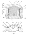
- the injection mold 10 shown in FIG. 1 has an upper one Tool part 12 and a lower part composed of several parts Tool part 14, which define the mold parting surface 16 between them.
- this molded part is one Side protection strip 20, which in Figures 2 to 4 in the demolded state is shown.
- the wall 22 is curved like a vault and forms thus after attachment to a body panel 24 (dashed lines in FIG. 2) indicated) a cavity 26 with the body panel 24.
- a cavity 26 can be the side protection strip 20 in the case of a corresponding Cushion the shock load in order to damage the body panel 24 to prevent.
- an edge region 30 which is essentially triangular in cross section is formed on both longitudinal edges of the strip 20. Its underside forms an adhesive surface 32 for a double-sided adhesive tape 34 which is parallel to the upper side of the body panel 24. Another boundary surface 36 of the edge region 30 faces the cavity 26 and runs perpendicular to the adhesive surface 32 and parallel to the molding direction or tool axis 18 within the injection mold 10.
- the outer border does not run out acutely according to the angle ⁇ , but is rounded and ultimately runs out at right angles to the body panel 24.
- each vertical wall thickness a of the molding starting from the Wall 22 with constant, comparatively smaller wall thickness a1, preferably 2 mm, this results first when entering the edge region 30 an increase in the wall thickness a up to a maximum value a2 corresponding to approximately 3 times a1. Then the falls Wall thickness a towards the edge.
- wall thickness a This at the transition from the wall 22 to the edge area 30 and also within the border area, wall thickness a would vary greatly without the Measures to be described below lead to the fact that the Visible area 28 clearly visible sink marks in the transition area and would have calluses. These are of different strengths Shrinkage of the plastic material when cooling from the liquid Condition due to the solid state.
- these sink marks are prevented by the fact that in the Area with comparatively larger wall thickness (or with varying Wall thickness) grooves 38 are incorporated on one of the visible surface 28 different side surface of the molding open.
- the grooves 38 are arranged and dimensioned such that the above different degrees of shrinkage is avoided.
- the width b of the grooves 38 is preferably 0.3-0.5 mm. Broader grooves would reduce the adhesive surfaces, thinner grooves cause the tool thinner spring steel sheets 40 and would accordingly be unstable in Area in which they protrude into the mold cavity 19.
- the transverse distance c of adjacent grooves 38 is in the range of comparatively smaller wall thickness a1 of approx. 2 mm.
- the grooves 38 run perpendicular to the respective adhesive surface 32 and thus (within the Injection mold 10) parallel to the axis 18.
- the grooves 38 end at a distance d from the Visible surface 28, which corresponds essentially to the wall thickness a1.
- the grooves 38 are produced in a particularly simple manner by that the lower tool part 14 with those already mentioned Spring steel sheets 40 is provided, which upwards into the cavity 19th protrude and arranged according to the desired grooves 38 and are dimensioned. Since they run parallel to the tool axis 18, there are no problems with demolding. There is one more to mention Partial cavity 19a, which is used to form a molded tongue.
- a wider molding e.g. 100 mm or more, not only the two are in the longitudinal direction of the bar extending edge area shape the molded body, but still one or two fastening areas, which are located approximately in the middle in the molded part the two edge areas can be provided.
- Such one Fastening or reinforcement area in the preferred form of a Longitudinal web 41 is only in Figure 2 with a broken outline indicated schematically. Again, these are longitudinal Reinforcement areas can be used as additional adhesive surfaces for 2-sided Adhesive tapes 34 can be designed.
- the grooves 38 be introduced because here the wall thickness perpendicular to the visible surface 28 a3 of the strip 20, the wall thickness a1 of the wall 22 considerably exceeds.
- the bar height of the end area 50 (and thus the local area there Wall thickness a4 of the strip 20) is approximately 11 mm at the apex S. she takes towards the edge areas 30, but it is always significantly higher than the wall thickness a1 of the wall 22.
- the two longitudinal edge regions 30 and the end region 50 and an optional second end region 50 at the other end of the Bar 20 are from a narrow web 54, about 0.4 mm high encompassed each outer edge.
- This web 54 is used for the applied double-sided adhesive tapes 34 after the application of the bar remain less visible on the body.
- the double-sided adhesive tapes 34 are about 0.8 mm thick, with about half of this thickness through the web 54, which is 0.4 mm high, is covered.
- At least one further reinforcement web 52b can be used End regions 50 may be formed spaced on the strip 20, as in FIG Figure 3 indicated on the right. This reinforcing web 52b is also with the to provide grooves 38 according to the invention.
- longitudinal adhesive surfaces 32 are expanded are the area that the at least one is transverse or inclined Reinforcing web 52a and 52b forms.
- the grooves 38 of the two longitudinally extending Edge areas 30 almost up to the respective outer ledge end and the Grooves 38 of the transverse or inclined reinforcing webs 52a, 52b approximately to the respective edge area 30.
- the grooves 38 of the transverse or oblique reinforcing webs 52a, 52b are made in the same way as the grooves 38 in the longitudinal ones Edge regions 30 through into the lower mold half of FIG. 1 used spring steel sheets 40 formed. This is easily possible since these spring steel sheets 40 also in the direction of the tool axis 18 run.
- the contour of the respective grooves 38 follows the Reinforcing web 52a or 52b approximates the contour of the boundary of the cavity 26 according to FIG. 2.
- the grooves 38 thus end in one Distance d2 from the visible surface 28 of substantially the thickness a1 of the corresponds to wall 22 following end region 50 according to FIG. 2.
- the Width b of the grooves 38 and their mutual distance c corresponds in each case that of the grooves 38 of the edge regions 30 as stated above.
- Last with comparatively narrow edge areas 30 and Reinforcing webs 52a, 52b can be used instead of two according to the invention
- Grooves 38 can only be designed with one groove 38.
- Wide edge regions 30 or reinforcing webs 52a, 52b can also three or more grooves 38 are formed.
- the side protection strip 20 described above is characterized by Particularly easy to manufacture, comparatively low use of materials and sink area-free visible surface 28.
Abstract
Description
- Figur 1
- einen Querschnitt eines erfindungsgemäßen Spritzwerkzeugs zur Herstellung einer erfindungsgemäßen Seitenschutzleiste,
- Figur 2
- einen Querschnitt der entformten Seitenschutzleiste (Schnittlinie ll, ll in Figur 3),
- Figur 3
- eine Unteransicht von einem linkseitigen Endbereich der Leiste gemäß Figur 2 mit quer verlaufenden Verstärkungsstegen, und
- Figur 4
- einen Schnitt durch diesen Endbereich (Schnittlinie IV, IV in Fig. 3).
Claims (23)
- Kunststoff-Spritzguß-Formteil mit aneinander angrenzenden Formteilbereichen unterschiedlicher Wandstärke (a) und gemeinsamer Sichtfläche (28) an einer Wandseite,
dadurch gekennzeichnet, dass
der Formteilbereich mit der vergleichsweise größeren Wandstärke (a2; a3, a4) mit Riefen (38) versehen ist, die in einer von der Sichtfläche (28) verschiedenen Seitenfläche des Formteils ausmünden und derart angeordnet und dimensioniert sind, dass die Sichtfläche (28) im Bereich des Übergangs zwischen den Formteilbereichen im wesentlichen frei von erkennbaren Einfallstellen bleibt. - Formteil nach Anspruch 1,
dadurch gekennzeichnet, dass
die Riefen (38) im Formteil in einem Abstand (d) zur Sichtfläche (28) enden, der im Bereich der vergleichsweise kleineren Wandstärke (a1) liegt. - Formteil nach Anspruch 2,
dadurch gekennzeichnet, dass
der Abstand (d) das 0,7 - 1,1-fache, besser das 0,9 - 1,05-fache, am Besten etwa das 1-fache der vergleichsweisen kleineren Wandstärke (a1) beträgt. - Formteil nach einem der vorhergehenden Ansprüche,
dadurch gekennzeichnet, dass
die Breite (b) der Riefen (38) des 0,025 - 0,3-fache, besser das 0,1-0,2-fache, am Besten das 0,125 - 0,175-fache der vergleichsweise kleineren Wandstärke (a1) beträgt. - Formteil nach einem der vorhergehenden Ansprüche,
dadurch gekennzeichnet, dass
die Breite (b) der Riefen (38) 0,05 - 0,9 mm, besser 0,3 - 0,5 mm beträgt. - Formteil nach Anspruch 5,
dadurch gekennzeichnet, dass
der Querabstand (c) benachbarter Riefen (38) das 0,3 - 1,2-fache, besser das 0,8 - 1,1-fache, noch besser das 0,9 - 1,05-fache, am Besten das 1-fache der vergleichsweise kleineren Wandstärke (a1) beträgt. - Formteil nach einem der vorhergehenden Ansprüche,
dadurch gekennzeichnet, dass
der Formteilbereich mit der vergleichsweise größeren Wandstärke (a2) einen Befestigungsbereich zur Befestigung des Formteils an einem Träger bildet. - Formteil nach einem der vorhergehenden Ansprüche,
dadurch gekennzeichnet, dass
der Formteilbereich mit der vergleichsweise größeren Wandstärke (a2) als Randbereich (30) des Formteils ausgebildet ist. - Formteil nach Anspruch 8,
dadurch gekennzeichnet, dass
der Randbereich mit nur einer Riefe ausgebildet ist. - Formteil nach Anspruch 8,
dadurch gekennzeichnet, dass
der Randbereich (30) mit zwei Riefen (38) ausgebildet ist. - Formteil nach Anspruch 8,
dadurch gekennzeichnet, dass
der Randbereich mit wenigstens drei Riefen ausgebildet ist. - Formteil nach einem der vorhergenden Ansprüche,
dadurch gekennzeichnet, dass
der Randbereich (30) in Längsrichtung verläuft. - Formteil nach einem der vorhergehenden Ansprüche,
dadurch gekennzeichnet, dass
der Randbereich (30) als Befestigungsfläche, vorzugsweise für Klebebänder (34), zur Befestigung des Bauteils an einem Träger ausgebildet ist. - Formteil nach Anspruch 13,
dadurch gekennzeichnet, dass
die Klebefläche (32) mit einem doppelseitig klebenden Band (34) versehen ist. - Formteil nach einem der vorhergehenden Ansprüche,
dadurch gekennzeichnet, dass
es als Kraftfahrzeugteil ausgebildet ist. - Formteil nach Anspruch 15,
dadurch gekennzeichnet, dass
es als Seitenschutzleiste (20) ausgebildet ist. - Spritzwerkzeug (10) für ein Formteil nach einem der vorhergehenden Ansprüche,
dadurch gekennzeichnet, dass
es mit Federstahlblechen (40) zur Ausformung der Riefen (38) versehen ist. - Spritzwerkzeug nach Anspruch 17,
dadurch gekennzeichnet, dass
die Federstahlbleche (40) parallel zur Ausformrichtung (Achse 18) verlaufen. - Verfahren zur Herstellung eines Formteils nach einem der Ansprüche
1 - 16 unter Verwendung des Spritzwerkzeug gemäß Anspruch 17 oder 18. - Kunststoff-Spritzguß-Formteil in Form einer Leiste (20) mit zwei einander gegenüberliegenden, längsverlaufenden Randbereichen (30) und einem beide Randbereiche (30) verbindenden Mittelbereich (22), und mit mindestens einem Verstärkungssteg (52a, 52b, 41), welcher längs oder quer oder schräg verläuft, wobei die beiden Randbereiche (30) und der mindestens eine Verstärkungssteg (41, 52a, 52b) größere Wandstärke (a2, a3, a4) aufweisen als der Mittelbereich
(22),
dadurch gekennzeichnet, dass
die beiden Randbereiche (30) und der mindestens eine Verstärkungssteg (52a, 52b, 41) jeweils mit mindestens einer Riefe (38) versehen sind, wobei die mindestens eine Riefe (38) in einem Abstand (d1; d2) zur Sichtfläche (28) ausläuft, so dass die Sichtfläche (28) im Bereich des Übergangs von den Formteilbereichen größerer Wandstärke (a2, a3, a4) zu den Formteilbereichen geringerer Wandstärke (a1) frei von erkennbaren Einfallstellen bleibt. - Kunststoff-Spritzguß-Formteil nach Anspruch 20,
dadurch gekennzeichnet, dass
der mindestens eine quer oder schräg verlaufende Verstärkungssteg (52a, 52b) am Ende der Leiste oder innerhalb der Leiste positioniert ist. - Kunststoff-Spritzguß-Formteil nach Anspruch 20 und 21,
dadurch gekennzeichnet, dass
der mindestens eine quer oder schräg verlaufende Verstärkungssteg keine Verbindung zu den Randbereichen hat. - Kunststoff-Spritzguß-Formteil nach einem der Ansprüche 20, 21 und
22,
dadurch gekennzeichnet, dass
zwischen dem mindestens einen quer oder schräg verlaufenden Verstärkungssteg (52) und den längsverlaufenden Randbereichen (30) eine Verbindung besteht.
Applications Claiming Priority (2)
| Application Number | Priority Date | Filing Date | Title |
|---|---|---|---|
| DE10234947 | 2002-07-31 | ||
| DE2002134947 DE10234947A1 (de) | 2002-07-31 | 2002-07-31 | Kunststoff-Spritzguß-Formteil |
Publications (3)
| Publication Number | Publication Date |
|---|---|
| EP1386713A1 true EP1386713A1 (de) | 2004-02-04 |
| EP1386713B1 EP1386713B1 (de) | 2009-06-17 |
| EP1386713B2 EP1386713B2 (de) | 2014-03-12 |
Family
ID=30010532
Family Applications (1)
| Application Number | Title | Priority Date | Filing Date |
|---|---|---|---|
| EP03017406.4A Expired - Fee Related EP1386713B2 (de) | 2002-07-31 | 2003-07-31 | Kunststoff-Spritzguss-Formteil |
Country Status (2)
| Country | Link |
|---|---|
| EP (1) | EP1386713B2 (de) |
| DE (2) | DE10234947A1 (de) |
Cited By (5)
| Publication number | Priority date | Publication date | Assignee | Title |
|---|---|---|---|---|
| EP1923611A1 (de) * | 2006-11-09 | 2008-05-21 | F.I.P. FORMATURA INIEZIONE POLIMERI S.p.A | Kugelventil |
| WO2014014403A1 (en) * | 2012-07-18 | 2014-01-23 | Scania Cv Ab | Vehicle panel portion designed to avoid indentations |
| CN105853183A (zh) * | 2016-03-31 | 2016-08-17 | 宁波优视佳视力保健有限公司 | 眼睛按摩器 |
| DE102005048220C5 (de) * | 2005-09-29 | 2018-01-18 | Magna Exteriors (Germany) Gmbh | Verfahren zur Herstellung einer Verkleidungsteilvariante für ein Kraftfahrzeug und Verkleidungsteil |
| CN114477323A (zh) * | 2022-01-10 | 2022-05-13 | 珠海格力电器股份有限公司 | 一种扣合结构及净水机 |
Families Citing this family (2)
| Publication number | Priority date | Publication date | Assignee | Title |
|---|---|---|---|---|
| DE102014207019A1 (de) | 2014-04-11 | 2015-10-15 | Bayerische Motoren Werke Aktiengesellschaft | Kunststoff-Formteil und Verfahren zu dessen Herstellung |
| DE102017204311A1 (de) | 2017-03-15 | 2018-09-20 | Bayerische Motoren Werke Aktiengesellschaft | Kunststoff-Formteil und Verfahren zu dessen Herstellung |
Citations (4)
| Publication number | Priority date | Publication date | Assignee | Title |
|---|---|---|---|---|
| JPH06321023A (ja) * | 1993-05-13 | 1994-11-22 | Honda Motor Co Ltd | プロテクタモール構造 |
| JPH1142981A (ja) * | 1997-07-30 | 1999-02-16 | Nippon Plast Co Ltd | 樹脂パネルの取付構造 |
| JPH11105071A (ja) * | 1997-10-06 | 1999-04-20 | Toyoda Gosei Co Ltd | 長尺サンドイッチ成形品 |
| JP2002103395A (ja) * | 2000-10-03 | 2002-04-09 | Meiwa Ind Co Ltd | 合成樹脂の射出成形方法及びその成形品 |
Family Cites Families (3)
| Publication number | Priority date | Publication date | Assignee | Title |
|---|---|---|---|---|
| JP3142438B2 (ja) † | 1994-03-14 | 2001-03-07 | 東海興業株式会社 | 厚肉部分を具えたモールディング及びその製造方法 |
| JP2835278B2 (ja) † | 1994-04-12 | 1998-12-14 | 出光石油化学株式会社 | 自動車用外装部品 |
| DE10041970A1 (de) † | 2000-08-25 | 2002-03-14 | Brocke Kg I B S | Kunststoffformteile als Anbauelemente von Kraftfahrzeugen und Verfahren zur Herstellung derselben |
-
2002
- 2002-07-31 DE DE2002134947 patent/DE10234947A1/de not_active Withdrawn
-
2003
- 2003-07-31 EP EP03017406.4A patent/EP1386713B2/de not_active Expired - Fee Related
- 2003-07-31 DE DE50311598T patent/DE50311598D1/de not_active Expired - Lifetime
Patent Citations (4)
| Publication number | Priority date | Publication date | Assignee | Title |
|---|---|---|---|---|
| JPH06321023A (ja) * | 1993-05-13 | 1994-11-22 | Honda Motor Co Ltd | プロテクタモール構造 |
| JPH1142981A (ja) * | 1997-07-30 | 1999-02-16 | Nippon Plast Co Ltd | 樹脂パネルの取付構造 |
| JPH11105071A (ja) * | 1997-10-06 | 1999-04-20 | Toyoda Gosei Co Ltd | 長尺サンドイッチ成形品 |
| JP2002103395A (ja) * | 2000-10-03 | 2002-04-09 | Meiwa Ind Co Ltd | 合成樹脂の射出成形方法及びその成形品 |
Non-Patent Citations (6)
| Title |
|---|
| DATABASE WPI Week 199926, Derwent World Patents Index; AN 1999-306899, XP002225429 * |
| DATABASE WPI Week 200248, Derwent World Patents Index; AN 2002-448540, XP002225428 * |
| PATENT ABSTRACTS OF JAPAN vol. 1995, no. 2 31 March 1995 (1995-03-31) * |
| PATENT ABSTRACTS OF JAPAN vol. 1999, no. 09 30 July 1999 (1999-07-30) * |
| PATENT ABSTRACTS OF JAPAN vol. 1999, no. 5 31 May 1999 (1999-05-31) * |
| PATENT ABSTRACTS OF JAPAN vol. 2002, no. 8 5 August 2002 (2002-08-05) * |
Cited By (7)
| Publication number | Priority date | Publication date | Assignee | Title |
|---|---|---|---|---|
| DE102005048220C5 (de) * | 2005-09-29 | 2018-01-18 | Magna Exteriors (Germany) Gmbh | Verfahren zur Herstellung einer Verkleidungsteilvariante für ein Kraftfahrzeug und Verkleidungsteil |
| EP1923611A1 (de) * | 2006-11-09 | 2008-05-21 | F.I.P. FORMATURA INIEZIONE POLIMERI S.p.A | Kugelventil |
| WO2014014403A1 (en) * | 2012-07-18 | 2014-01-23 | Scania Cv Ab | Vehicle panel portion designed to avoid indentations |
| CN104507657A (zh) * | 2012-07-18 | 2015-04-08 | 斯堪尼亚商用车有限公司 | 设计为避免压痕的车辆面板构件 |
| CN104507657B (zh) * | 2012-07-18 | 2017-10-27 | 斯堪尼亚商用车有限公司 | 设计为避免压痕的车辆面板构件 |
| CN105853183A (zh) * | 2016-03-31 | 2016-08-17 | 宁波优视佳视力保健有限公司 | 眼睛按摩器 |
| CN114477323A (zh) * | 2022-01-10 | 2022-05-13 | 珠海格力电器股份有限公司 | 一种扣合结构及净水机 |
Also Published As
| Publication number | Publication date |
|---|---|
| DE50311598D1 (de) | 2009-07-30 |
| DE10234947A1 (de) | 2004-02-12 |
| EP1386713B1 (de) | 2009-06-17 |
| EP1386713B2 (de) | 2014-03-12 |
Similar Documents
| Publication | Publication Date | Title |
|---|---|---|
| DE202016102034U1 (de) | Fußbodenpaneel zur Bildung eines Fußbodenbelags | |
| AT398379B (de) | Alpinski mit konvergierender oberer fläche | |
| DE4133144A1 (de) | Aufpralltraeger | |
| DE3229762A1 (de) | Verfahren zur herstellung von gegenstaenden aus expandiertem kunststoffmaterial mit verschiedenen physikalischen eigenschaften | |
| EP1386713A1 (de) | Kunststoff-Spritzguss-Formteil | |
| WO2012028605A1 (de) | Türinnenverkleidung für fahrzeugtüren | |
| DE2526914C3 (de) | Stoßfänger aus nachgiebigem Kunststoff für Kraftfahrzeuge | |
| DE3107321A1 (de) | Streifen, insbesondere dichtungsstreifen, sowie form zu seiner herstellung | |
| DE3247343A1 (de) | Formkoerper, bestehend aus unter druck- und waermebeaufschlagung verpressten und oberflaechenkaschierten bindemittelhaltigen faser- bzw. partikelfoermigen werkstoffen | |
| DE2945541A1 (de) | Herstellungsverfahren fuer industrielle teile, insbesondere dichtungsklappen fuer klimaanlagen, und danach hergestelltes industrielles teil | |
| DE3517426A1 (de) | Ski sowie verfahren zur herstellung desselben | |
| EP0954435B1 (de) | Verfahren zur herstellung einer verbundwanne | |
| DE2231229A1 (de) | Profilkoerper zum aufbau von skiern und verfahren zur verwendung solcher koerper | |
| DE102007026653B4 (de) | Fahrzeugreifen aus vulkanisierbarem Werkstoff | |
| DE1916043A1 (de) | Schibauteil | |
| DE69919482T2 (de) | Strangpressmundstück zur Herstellung von Wabenkörpern | |
| DE4224145C2 (de) | Verfahren zur Herstellung eines Schließklobens für einen Kraftfahrzeug-Türverschluß | |
| EP3885009B1 (de) | Gleitbrettkörper mit holzkern und pu schaum verbindungschichten unterhalb und/oder oberhalb vom kern | |
| EP0038955A2 (de) | Geblasene Zier- oder Schutzleiste | |
| EP2562447B1 (de) | Schaltgabel | |
| EP3676086B1 (de) | Fahrzeug-sandwichbauteil und verfahren zum herstellen eines fahrzeug-sandwichbauteils | |
| EP1676684B1 (de) | Verfahren zur Herstellung eines Bausteins | |
| WO2022079042A1 (de) | Bauprodukt und verfahren | |
| DE19714183C2 (de) | Verfahren zur Herstellung eines aus Fasermaterial oder Vlies bestehenden Hohlkörpers und Hohlkörper | |
| AT413996B (de) | Ziegel |
Legal Events
| Date | Code | Title | Description |
|---|---|---|---|
| PUAI | Public reference made under article 153(3) epc to a published international application that has entered the european phase |
Free format text: ORIGINAL CODE: 0009012 |
|
| AK | Designated contracting states |
Kind code of ref document: A1 Designated state(s): AT BE BG CH CY CZ DE DK EE ES FI FR GB GR HU IE IT LI LU MC NL PT RO SE SI SK TR |
|
| AX | Request for extension of the european patent |
Extension state: AL LT LV MK |
|
| 17P | Request for examination filed |
Effective date: 20040609 |
|
| AKX | Designation fees paid |
Designated state(s): CZ DE FR GB IT SK |
|
| 17Q | First examination report despatched |
Effective date: 20061124 |
|
| GRAP | Despatch of communication of intention to grant a patent |
Free format text: ORIGINAL CODE: EPIDOSNIGR1 |
|
| GRAS | Grant fee paid |
Free format text: ORIGINAL CODE: EPIDOSNIGR3 |
|
| GRAA | (expected) grant |
Free format text: ORIGINAL CODE: 0009210 |
|
| AK | Designated contracting states |
Kind code of ref document: B1 Designated state(s): CZ DE FR GB IT SK |
|
| REG | Reference to a national code |
Ref country code: GB Ref legal event code: FG4D Free format text: NOT ENGLISH |
|
| REF | Corresponds to: |
Ref document number: 50311598 Country of ref document: DE Date of ref document: 20090730 Kind code of ref document: P |
|
| PLBI | Opposition filed |
Free format text: ORIGINAL CODE: 0009260 |
|
| PLAX | Notice of opposition and request to file observation + time limit sent |
Free format text: ORIGINAL CODE: EPIDOSNOBS2 |
|
| 26 | Opposition filed |
Opponent name: REHAU AG & CO. Effective date: 20100315 |
|
| PLAF | Information modified related to communication of a notice of opposition and request to file observations + time limit |
Free format text: ORIGINAL CODE: EPIDOSCOBS2 |
|
| PLBB | Reply of patent proprietor to notice(s) of opposition received |
Free format text: ORIGINAL CODE: EPIDOSNOBS3 |
|
| APAH | Appeal reference modified |
Free format text: ORIGINAL CODE: EPIDOSCREFNO |
|
| APBM | Appeal reference recorded |
Free format text: ORIGINAL CODE: EPIDOSNREFNO |
|
| APBP | Date of receipt of notice of appeal recorded |
Free format text: ORIGINAL CODE: EPIDOSNNOA2O |
|
| APBU | Appeal procedure closed |
Free format text: ORIGINAL CODE: EPIDOSNNOA9O |
|
| PUAH | Patent maintained in amended form |
Free format text: ORIGINAL CODE: 0009272 |
|
| STAA | Information on the status of an ep patent application or granted ep patent |
Free format text: STATUS: PATENT MAINTAINED AS AMENDED |
|
| 27A | Patent maintained in amended form |
Effective date: 20140312 |
|
| AK | Designated contracting states |
Kind code of ref document: B2 Designated state(s): CZ DE FR GB IT SK |
|
| REG | Reference to a national code |
Ref country code: DE Ref legal event code: R102 Ref document number: 50311598 Country of ref document: DE |
|
| REG | Reference to a national code |
Ref country code: DE Ref legal event code: R102 Ref document number: 50311598 Country of ref document: DE Effective date: 20140312 |
|
| REG | Reference to a national code |
Ref country code: SK Ref legal event code: T5 Ref document number: E 5630 Country of ref document: SK |
|
| PGFP | Annual fee paid to national office [announced via postgrant information from national office to epo] |
Ref country code: CZ Payment date: 20140724 Year of fee payment: 12 |
|
| PGFP | Annual fee paid to national office [announced via postgrant information from national office to epo] |
Ref country code: SK Payment date: 20140728 Year of fee payment: 12 Ref country code: GB Payment date: 20140721 Year of fee payment: 12 Ref country code: FR Payment date: 20140721 Year of fee payment: 12 |
|
| PGFP | Annual fee paid to national office [announced via postgrant information from national office to epo] |
Ref country code: IT Payment date: 20140730 Year of fee payment: 12 |
|
| REG | Reference to a national code |
Ref country code: SK Ref legal event code: MM4A Ref document number: E 5630 Country of ref document: SK Effective date: 20150731 |
|
| GBPC | Gb: european patent ceased through non-payment of renewal fee |
Effective date: 20150731 |
|
| PG25 | Lapsed in a contracting state [announced via postgrant information from national office to epo] |
Ref country code: CZ Free format text: LAPSE BECAUSE OF NON-PAYMENT OF DUE FEES Effective date: 20150731 Ref country code: GB Free format text: LAPSE BECAUSE OF NON-PAYMENT OF DUE FEES Effective date: 20150731 Ref country code: IT Free format text: LAPSE BECAUSE OF NON-PAYMENT OF DUE FEES Effective date: 20150731 Ref country code: SK Free format text: LAPSE BECAUSE OF NON-PAYMENT OF DUE FEES Effective date: 20150731 |
|
| REG | Reference to a national code |
Ref country code: FR Ref legal event code: ST Effective date: 20160331 |
|
| PG25 | Lapsed in a contracting state [announced via postgrant information from national office to epo] |
Ref country code: FR Free format text: LAPSE BECAUSE OF NON-PAYMENT OF DUE FEES Effective date: 20150731 |
|
| PGFP | Annual fee paid to national office [announced via postgrant information from national office to epo] |
Ref country code: DE Payment date: 20160630 Year of fee payment: 14 |
|
| REG | Reference to a national code |
Ref country code: DE Ref legal event code: R119 Ref document number: 50311598 Country of ref document: DE |
|
| PG25 | Lapsed in a contracting state [announced via postgrant information from national office to epo] |
Ref country code: DE Free format text: LAPSE BECAUSE OF NON-PAYMENT OF DUE FEES Effective date: 20180201 |