EP1384801A1 - Vorrichtung und Verfahren zum automatischen Einziehen - Google Patents
Vorrichtung und Verfahren zum automatischen Einziehen Download PDFInfo
- Publication number
- EP1384801A1 EP1384801A1 EP02016703A EP02016703A EP1384801A1 EP 1384801 A1 EP1384801 A1 EP 1384801A1 EP 02016703 A EP02016703 A EP 02016703A EP 02016703 A EP02016703 A EP 02016703A EP 1384801 A1 EP1384801 A1 EP 1384801A1
- Authority
- EP
- European Patent Office
- Prior art keywords
- yarn
- heddle
- dummy
- heddles
- frame designating
- Prior art date
- Legal status (The legal status is an assumption and is not a legal conclusion. Google has not performed a legal analysis and makes no representation as to the accuracy of the status listed.)
- Withdrawn
Links
- 238000000034 method Methods 0.000 title claims abstract description 29
- 210000000887 face Anatomy 0.000 claims abstract description 11
- 208000019300 CLIPPERS Diseases 0.000 claims description 56
- 208000021930 chronic lymphocytic inflammation with pontine perivascular enhancement responsive to steroids Diseases 0.000 claims description 56
- 239000004744 fabric Substances 0.000 claims description 42
- 238000009941 weaving Methods 0.000 claims description 32
- 238000010276 construction Methods 0.000 claims description 27
- 238000003860 storage Methods 0.000 claims description 16
- 230000007246 mechanism Effects 0.000 claims description 13
- 238000005520 cutting process Methods 0.000 claims description 9
- 238000003780 insertion Methods 0.000 claims description 9
- 230000037431 insertion Effects 0.000 claims description 9
- 238000004804 winding Methods 0.000 claims description 8
- 230000004044 response Effects 0.000 claims description 4
- 238000012546 transfer Methods 0.000 claims description 4
- 208000037805 labour Diseases 0.000 description 5
- 238000004519 manufacturing process Methods 0.000 description 4
- 230000008569 process Effects 0.000 description 4
- 238000007796 conventional method Methods 0.000 description 3
- 238000005516 engineering process Methods 0.000 description 3
- 238000002360 preparation method Methods 0.000 description 3
- 238000012545 processing Methods 0.000 description 3
- 238000013459 approach Methods 0.000 description 2
- TVEXGJYMHHTVKP-UHFFFAOYSA-N 6-oxabicyclo[3.2.1]oct-3-en-7-one Chemical compound C1C2C(=O)OC1C=CC2 TVEXGJYMHHTVKP-UHFFFAOYSA-N 0.000 description 1
- 235000014676 Phragmites communis Nutrition 0.000 description 1
- 230000008859 change Effects 0.000 description 1
- 230000003111 delayed effect Effects 0.000 description 1
- 238000013461 design Methods 0.000 description 1
- 238000011161 development Methods 0.000 description 1
- 230000018109 developmental process Effects 0.000 description 1
- 230000005484 gravity Effects 0.000 description 1
- 230000008520 organization Effects 0.000 description 1
- 239000000758 substrate Substances 0.000 description 1
Images


Classifications
-
- D—TEXTILES; PAPER
- D03—WEAVING
- D03J—AUXILIARY WEAVING APPARATUS; WEAVERS' TOOLS; SHUTTLES
- D03J1/00—Auxiliary apparatus combined with or associated with looms
- D03J1/14—Apparatus for threading warp stop-motion droppers, healds, or reeds
Definitions
- the present invention relates to an automatic heddling apparatus and more particularly to an automatic heddling apparatus which is used in a fabric producing process in that the warp yarns and weft yarns to be woven are interlaced with each other on an ordinary weaving machine, a narrow fabric weaving machine, a narrow-fabric-dedicated needle weaving machine, etc., and which is used especially in its preparation steps in manufacture of the fabric, which is used for automatically passing warp yarns of a fabric to be woven through a corresponding plurality of heddles provided in each one of predetermined heddle frames, respectively.
- warp and weft yarns are interlaced with each other to be woven into a band on a weaving machine, so that it is necessary to pass all of the warp yarns which make up a fabric one by one through heddles specified in a weave construction chart prepared on the basis of a weaving design of a desired fabric, specifically by, for example, using a wire-shaped or narrow thin-sheet-shaped tool having a hook at its tip to manually pass the warp yarns one by one through each yarn passing eye, i.e., heddle eyes of the heddles typically.
- paired two operators are engaged in warp passing operation as positioned respectively in front of (a side on which the fabric is discharged out) and behind (a side on which the warp yarns are supplied) a heddle-frame mounting section of a weaving machine to which a necessary number of heddle frames to which the heddles are attached, are mounted.
- the operator positioned on the front side inserts the above-mentioned tool through the yarn passing eye, i.e., heddle eyes, of the corresponding heddle in a heddle frame specified by the weave construction chart and then stands by.
- the yarn passing eye i.e., heddle eyes
- the other operator positioned on the rear side picks up one warp yarn out of a group of the warp yarns leased beforehand, from an end portion thereof and brings it by his finger tip to the heddle, and engages it at the tip hook of the tool already inserted through the yarn passing eye of the heddle.
- the operator on the front side pulls out the tool through the yarn passing eye and draws the warp yarn toward him, thus completing heddling of one warp yarn.
- This heddling operation is repeated for each of the warp yarns until all of them are passed through the yarn passing eyes of the heddles specified by the weave construction chart.
- a common technical concept for these two cases is a technical conception in that "a warp yarn is passed through the yarn passing eye of each one of the heddles attached in a heddle frame manually or using a machine".
- the present invention basically employs the following technological conception.
- a first aspect of the present invention provides an automatic heddling apparatus wherein a plurality of heddles removed from each one of a plurality of heddle frames are integrally collected into one group in a heddle integrating and holding means, so that each one of flat faces of the respective heddles may face opposite to each other, then a dummy yarn being passed through each one of the heddle eyes provided on each one of the heddles, simultaneously, while the heddles being in a collected state, thereafter each one of the heddles being carried from the heddle integrating and holding means arranged at a collecting position of the heddles to a predetermined respective heddle frame designating section in a heddle frame designating means, individually, while each one of the heddles being engaged with the dummy yarn; while a second aspect of the present invention is an automatic heddling apparatus comprising:
- an automatic heddling method and apparatus related to the present invention has the above-mentioned technological configuration, it is possible to automatically pass warp yarns of a fabric to be woven on a weaving machine through corresponding heddles of corresponding heddle frames in a preparatory step for weaving the fabric using the weaving machine to thereby streamline and save on a human labor of a job for drawing the warps through the heddles, thus enabling greatly reducing the manufacturing costs as compared to the conventional technologies.
- a plurality of heddles can be removed from the respective heddle frames, each being mounted on a weaving machine, utilizing a specifically designed heddle frame construction in that the heddles can be easily inserted thereunto and removed therefrom.
- An automatic heddling apparatus of the present invention is used to automatically pass a predetermined dummy yarn through all the heddles not by hand.
- heddles through which the predetermined dummy yarn is passed are all stored in heddle storing means (heddle frame designating section) configured so as to be attachable to or removable from the automatic heddling apparatus.
- Each one of the heddles with the dummy yarn passed therethrough, respectively, is inserted into the respective heddle frames which being either dismounted from or mounted on a weaving machine, from the removable heddle storing means (heddle frame designating section), in a sliding manner, easily in short time, with utilizing a suitable device or manually, to thereby arrange a predetermined number of heddles in each one of the heddle frames and to provide a group of the heddle frames in each of which the dummy yarn is passed through each one of the yarn passing eyes provided on all the heddles, automatically and effectively in short time and thereafter, to enable this predetermined number of the heddle to remount on a predetermined weaving machine, thus contributing greatly in reducing the human labor for heddling as compared to the conventional method.
- the present invention employs a technological concept of attaching a heddle through which a warp yarn is already passed to a heddle frame to thereby tie the warp yarn in the present invention, this concept being totally different from the conventional technological concept of passing a yarn through a heddle.
- each one of the heddles with a yarn as already been passed therethrough is configured to be stored in the heddle storing means (heddle frame designating section) so devised as to be easily attached to a heddle frame on a weaving machine, thus making it possible to remount any one of the heddles with a dummy yarn passed therethrough stored in this heddle storing means (heddle frame designating section) to the heddle frame easily in short time by hand or automatically.
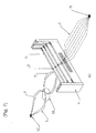
- FIGs. 1 to 3 show a basic configuration of one example of an automatic heddling method related to the present invention, in that an automatic heddling apparatus 100 is shown and which further comprises a plurality of heddles 2 detached from a plurality of heddle frames the are integrally collected with flat faces 11 of the heddles 2 as opposed to each other, a dummy yarn 4 is inserted through a yarn passing eye 3 of each of the plurality of heddles 2 as collected, and each one of the plurality of heddles 2 is individually carried from a collection position 5 thereof from the respective heddle frame designating means 6,respectively, while each one of the heddles being engaged with the dummy yarn.
- a heddle integrating and holding means 7 is provided which is so configured as to stack the plurality of heddles 2 with the flat faces 11 thereof as opposed to each other as shown in the figure.
- the heddle integrating and holding means 7 in the present invention may be comprised of a framework the3 having a pair of guide portions the2 with a gap almost the same as a width of the heddles 2 or of a container having a slit matching a shape of the heddles 2.
- the heddle integrating and holding means 7 may be arranged perpendicularly or inclined by a predetermined angle or in a case may be, it may be configured so as to hold the heddles 21rein with keeping them in up-right configuration, i.e., perpendicular to the horizontal direction.
- the plurality of heddles 2 integrated and held in the heddle integrating and holding means 7 are all required to be arranged so that each one of the yarn passing eyes, i.e., the heddle eyes 3 thereof can be positioned to be coaxially alined with each other.
- dummy-yarn holding means 8 comprising a yarn bobbin or the like, for holding the dummy yarn 4 is arranged below the hedle integrating and holding means 7 to thereby insert the dummy yarn 4 as taken out from the dummy-yarn holding means 8 commonly through the yarn passing eye 3 of each of the plurality of heddles 2 as a common dummy yarn 4 by using a compressed air or suction air stream or appropriate automatic or manual yarn insertion means 9 provided with a thin guide rod, hook, or the like.
- the end of the dummy yarn 4 having passed through the yarn passing eye 3 of each of the heddles 2 is once engaged at appropriate dummy-yarn end holding means 10.
- the dummy-yarn insertion means 9 is configured to be arranged to be moved above the heddle integrating and holding means 7 from a predetermined position at a necessary moment and return to the predetermined position after the dummy yarn 4 had been completely inserted.
- the heddle integrating and holding means 7 of the present invention is provided at a bottom thereof with heddle lift-up means 14 for lifting up the plurality of heddle 2 contained therein, at a lower end of the heddle integrating and holding means 7 so that, as mentioned above, the heddles 2 housed in the heddle integrating and holding means 7 may be easily taken out from the heddle integrating and holding means 7, since each one of them is needed to be taken out and to be transferred to a predetermined portion, one by one, respectively.
- Such heddle lift-up means the4 may be comprised of a spring having a predetermined level of resiliency or be configured to move upward at a predetermined pitch in response to the operation of heddle grip means controlling means 35 for the heddles 2.
- a plurality of heddle frame designating section 18 are provided in the heddle frame designating means 6 arranged near the heddle integrating and holding means 7, and each one of the heddle frame designating section 18 preferably has a function to hold one or more of the heddles 2 with the dummy yarn 4 inserted therethrough already, therein and is arranged in opposite to each one of a plurality of heddle frames, respectively.
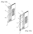
- the heddle frames the used in the present invention are configured to have a side thereof being easily removable, so that the heddles 2 arranged in the heddle frame the can be taken out of it with a condition in that a frame section 29 of a side thereof is removed and also that, conversely, heddles 2 with the dummy yarn 4 as inserted therethrough, can be inserted in a sliding manner into the heddle frame 1.
- the heddle frame designating means 6 is provided with a board 19 and, at two ends of the board 19, respectively a plurality of first rod 16, 16' , 16'', 16''', ..., arranged in a row with a spacing W intervening interposed therebetween which is roughly equal to the width of the heddles 2 and a plurality of second rods 17, 17', 17'', 17''',..., arranged as opposed to the first rods 16 with a spacing L interposed therebetween which is roughly equal to the length of the heddles 2, in such a configuration that the first rods 16 and 16' and the second rods 17 and 17' are combined to form the first heddle frame designating section 18 and the first rods 16' and 16'' and the second rods 17' and 17'' are combined to form the second heddle frame designating section 18'.
- a center-to-center spacing X between the first and second heddle frame designating section 18 and 18' is set to be roughly equal to a centerline-to-centerline spacing between a plurality of heddle frames the arranged side by side.
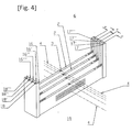
- each one of the individual heddle frame designating sections 18 provided in the heddle frame designating means 6 in the present invention since the operation in that a plurality of the heddles 2 being once stacked into each one of the heddle frame designating section 18 and each one of the heddles 2 having the dummy yarn 4 which already been passed through the respective heddle eyes 3 provided on each one of the heddles 2, are collectively moved into each one of the heddle frames the each being arranged in opposite to each one of the heddle frame designating section 18, respectively, is applied to the heddle frame designating section 18, it is preferable in that as shown in Fig. 4, an upper part of each of the heddle frame designating section 18 is kept opened.
- the heddle frame designating means 6 is provided on its front and rear sides thereof with a first dummy-yarn holding member 20-1 and a second dummy-yarn holding member 20-2 for holding the respective ends of the dummy yarn 4, respectively.
- the first dummy-yarn holding member 20-1 for engaging one end of the dummy yarn 4 inserted through the heddle 2
- the second dummy-yarn holding member 20-2 for engaging the other end of the dummy yarn 4 inserted through the heddle 2.
- yarn clipper means 15 is provided so as to grip and hold the dummy yarn 4 as inserted through the yarn passing eye 3 of the heddle 2 and one end portion thereof being fixed the dummy-yarn end holding means 10 and yarn clipper means 15 is so configured to move with the dummy yarn to a predetermined yarn clipper movement end position Y.
- the yarn clipper means 15 grips the dummy yarn 4 at its end thereof on a portion in the vicinity of the dummy-yarn end holding means 10 as shown in Fig. 1 and moves with the dummy yarn 4 to the yarn clipper movement end position Y beyond the second dummy-yarn-holding member 20-2 so as to extend the dummy-yarn 4 therebetween.
- the yarn clipper means 15 is configured so as to return to a yarn clipper means initial position Q in the vicinity of the dummy-yarn end holding means 10 at a predetermined timing after the dummy yarn 4 is extended therefor.
- reference numerals 21 and 22 indicate respective yarn guide members provided in a yarn passage over which the dummy yarn 4 is extended, which have a function to grip and release the dummy yarn 4 as well as elevate and lower its position in order to change its yarn passage, and further between the yarn guide member 21 and the dummy-yarn end holding means 10, there is provided a yarn cutter 23 and a yarn gripping section 24 which has a function to grip and release the dummy yarn 4.
- a heddle gripping and conveying means 25 is provided in the heddle integrating and holding means 7, to pick up the heddles 2 integrated and held in the heddle integrating and holding means 7 one by one therefrom and convey it along the extended dummy yarn 4, respectively to predetermined one of the heddle frame designating section 18 in the heddle frame designating means 6.
- each one of the heddles 2 is conveyed by the heddle gripping and conveying means 25 along the dummy yarn 4 thus extended, to a specifically selected heddle frame designating section 18 among a plurality of the heddle frame designating sections 18, in the heddle frame designating means 6, and which corresponding to a specifically designated heddle frame the.
- the heddle gripping and conveying means 25 has means for gripping the heddles 2 by utilizing by a suction means, an electromagnetic mechanism or a mechanical mechanism, so as to perform an operation for gripping each one of the heddle 2 and for conveying the same, respectively.
- the heddle gripping and conveying means 25 also has a function to release the heddle 2 at a place corresponding to the specifically designated heddle frame designating section 18 in the heddle frame designating means 6 so as to insert the heddle 2 which still keeping the dummy yarn 4 passed through the heddle eyes provided on each one of the heddles 2, into the heddle frame designating section 18, respectively.
- the heddle gripping and conveying means 25 may just carry the heddle 2 into the predetermined heddle frame designating section 18 by gravity fall in natural or may also use appropriate descending means as well to insert the heddle 2 into the heddle frame designating section 18.
- the dummy yarn 4 can be easily engaged with the first and second dummy-yarn holding members 20-1 and 20-2,respectively, so that each one of the end portions of the dummy yarns 4 is easily held by the dummy yarn end gripping mechanism provided at these dummy-yarn holding members 20-1 and 20-2.
- the yarn clipper 15 releases the end of the dummy yarn 4 to then return to the yarn clipper means initial position Q, while at the same time, on the side of the first dummy-yarn holding member 20-1, with the yarn gripping section 24 as gripping the dummy yarn 4, the yarn cutter 23 cuts the dummy yarn 4 extended between the yarn gripping section 24 and the first dummy-yarn holding member 20-1.
- the yarn guide members 21 and 22 release the end of the dummy yarn 4 and returns to a position along the passage over which the dummy yarn 4 is extended and then releases the dummy yarn 4 to stand by for receiving the next dummy yarn 4.
- the heddle gripping and conveying means 25 returns to a heddle gripping and conveying section initial position P as shown in Fig. 1 to stand by for causing the next heddle 2 to be moved, while at the same time, after having released the end of the dummy yarn 4, the yarn clipper means 15 also returns to the yarn clipper means initial position Q in the vicinity of the heddle integrating and holding means 7 and grips the dummy yarn 4 extended over between the dummy-yarn holding means 10 and the yarn gripping section 24 to prepare for the next operation.
- the yarn gripping section 24 releases the dummy yarn 4 from a gripped state and once evacuates from the moving passage of the yarn clipper means 15 together with the yarn cutter 23 and then stands by.
- the dummy yarn 4 is cut so that a predetermined length of the dummy yarn 4 may be kept before and after each of the heddles 2 and these end portions of the dummy yarn may be securely held by a predetermined method.
- part of the dummy yarn 4 which is arranged opposite to the one end of the dummy yarn 4 in the heddle frame designating means 6 and also which is extended into an automatic heddling apparatus for the heddles is cut at the predetermined position between the heddle integrating and holding means 7 and the heddle frame designating means 6 to be gripped by a predetermined second dummy-yarn holding section 20-1.
- leasing means 26 is provided between the heddle frame designating means 6 and the second dummy-yarn holding member 20-2.
- one end of the dummy yarn 4 gripped by the second dummy-yarn holding member 20-2 is leased as gripped by the second dummy-yarn holding member 20-2.
- the number of the leasing members 26 is not limited to one; for example, it is possible that each one of the dummy yarns 4 to be passed through either one of the heddles 2 for the ground yarns, for the selvage yarns, for connecting yarns or the like, can be leased by different leasing means 26 from each other, respectively.
- each one of the leasing means 26 is provided with two leasing bars 27 arranged on a rotary substrate 28 so as to oppose to each other with respect to a rotation center thereof, which rotary board 28 is configured so as to rotate by 90 degrees at each time when one of the dummy yarns 4 is inserted in order to insert a predetermined leasing yarn into its own space formed between those two bars.
- three leasing means 26 is provided.
- the heddle frame designating means 6 may be rotated by 90 degrees to cause an end opening 50 in the respective heddle frame designating section.
- the heddle frame designating means 6 may be provided at each of its sites with the heddle frame designating section 18 which integrates the heddles 2, and the heddle frame designating means 6 is configured so that it can be stored at a predetermined site apart from this apparatus, with a predetermined number of the heddles 2 having the dummy yarn 4 inserted therethrough and which being integrated in each of the respective heddle frame designating section 18 of the heddle frame designating means 6, or a group of heddle frames, each containing a plurality of heddles 2 each having the dummy yarn 4 inserted therethrough, can be stored at the above-mentioned predetermined site, after each one of a plurality of heddles 2 had been inserted into each one of the heddle frames the, respectively.
- each one of the heddles 2 collected and stacked in the heddle integrating and holding means 7 is all carried into the specified respective heddle frame designating section 18 in the heddle frame designating means 6 with the dummy yarn 4 as inserted therethrough according to the above-mentioned method and procedure and then all of the heddles 2 held in the respective heddle frame designating section 18 with the dummy yarn as inserted therethrough are simultaneously transferred into the heddle frames the arranged in opposite to correspondence to the respective heddle frame designating section 18 or before the heddles are transferred into these heddle frames the, each one of a plurality of end portions of the second dummy-yarn group ends 62 of the dummy yarns 4 being already leased and gripped by the second dummy-yarn holding member 20-2, is sequentially connected to the respective ends of a group of warp yarns already warped by another step, starting from the outermost one of the warp yarn group.
- Such an operation of tying the warp yarns can be carried out using a publicly known automatic yarn tying apparatus, an air splicer, or the like.
- a group of the yarn end portions of the first dummy-yarns 6the of the plurality of dummy yarns 4 gripped by the first dummy-yarn holding member 20-1 is connected to a predetermined winging means, that is, a fabric winding roller or the like for winding up a fabric would be woven later on.
- the various means or devices provided to An automatic heddling apparatus 100 are configured so as to operate at a predetermined timing according to a predetermined program to thereby automatically perform all the operations such as insertion of the dummy yarn 4 through the heddles 2, picking up and carriage of each of the heddles 2 by the heddle gripping and conveying means 25, carriage of the dummy yarn 4 by the yarn clipper means 15, an operation of the yarn guide members 21 and 22, holding and releasing of the dummy-yarn holding members 20-1 and 20-2, an operation of the yarn gripping section 24 and the yarn cutter 23, cutting of the dummy yarn 4, or the like.
- fabric construction information storage means 30 for storing information of an weave construction chart showing a desired construction of a fabric to be woven beforehand
- control information generation means 3the for generating, based on the fabric construction information stored in this fabric construction information storage means 30, control information as to indicate to which one of the heddle frames the a predetermined heddle 2 with the dummy yarn 4 as inserted therethrough already is to be transferred and control information as to include designation of the respective position of the heddle frame designating section 18 in the heddle frame designating means 6 as to correspond to the heddle frame the
- operation control means 32 for processing various operations by these means based on the control information sent from this control information creation means 31 and for outputting the respective control signals
- the third heddle frame designating section 18-3 which corresponds to this third heddle frame1-3 is selected, so that the heddle gripping and conveying means 25 picks up the first heddle 2 from the heddle integrating and holding means 7 and moves it along the extended dummy yarn 4 and then inserts it with the dummy yarn 4 as inserted therethrough, in the third heddle frame designating section 18-3.
- the heddle frame designating section 18-1 which corresponds to this first heddle frame 1-1 is selected, so that the heddle gripping and conveying means 25 picks up the second heddle 2 from the heddle integrating and holding means 7 and moves it along the extended dummy yarn 4 and then inserts it with the dummy yarn 4 as inserted therethrough, in the first heddle frame designating section 18-1.
- Such operations are sequentially repeated automatically until a time when a certain number of the heddles among the heddles stacked in the heddle integrating and holding means 7, corresponding to the number designated by the fabric construction information storage means 30, have completely be transferred into all of the respective heddle frame designating sections 18 of the heddle frame designating means 6.
- a predetermined number of the heddles 2 are stacked into each one of the heddle frame designating section 18 of the heddle frame designating means 6 and a predetermined length of the dummy yarn 4 as inserted through the yarn passing eye 3 of each of the heddles 2, formed by cutting operation, is disposed on both sides of the respective heddle frame designating section 18, thus forming a shape of a heddling processing component 63 as to have the first and second dummy-yarn ends groups 6the and 62 formed at the two ends of each one of the heddle frame designating section 18, respectively.
- the heddling processing component 63 may be stored as thus shaped at a predetermined department and then picked up at a necessary moment and supplied to the heddle frame 1.
- the yarn clipper means 15 grips the dummy yarn 4 extended over between the dummy-yarn end holding means 10 and the yarn gripping section 24 at the yarn clipper means initial position Q near the heddle integrating and holding means 7.
- the yarn gripping section 24 and the dummy-yarn end holding means 10 stop gripping of the dummy yarn 4 and release it and then withdraw by its-self from the position as it was to such a position as not to interfere with the movement of the yarn clipper 15, thus standing by in preparation for the next operation.
- the yarn clipper means 15 moves as gripping the dummy yarns 4 over the heddle frame designating means 6 to the yarn clipper movement end position Y outside the second dummy-yarn holding section 20-2 while at the same time stretching the dummy yarns 4.
- the yarn clipper means 15 moves, the dummy yarns 4 slides through the yarn passing eyes 3 in each of the heddles 2 in the heddle integrating and holding means 7 to be sequentially pulled out from the dummy-yarn holding means 8 in configuration.
- the yarn clipper means 15 may hand over the gripping of the dummy yarns 4 to the yarn guide member 22 to return to the above-mentioned yarn clipper means initial position Q in configuration.
- such a yarn guide member 22 functions to lower its position while it gripping the dummy yarns 4, to thereby engages the ends of the dummy yarns 4 with the second dummy-yarn holding member 20-2.
- the leasing means 26 rotates by 90 degrees to form a lease in the dummy yarns 4 when they have passed the center thereof.
- the leasing means 26 repeatedly rotates in normal and reverse directions by 90 degrees at each time when the yarn passes therethrough, thus forming a lease in a group of the dummy yarns 4 when they have passed through the mechanism.
- the heddle gripping and conveying means 25 moves to the position of the heddle integrating and holding means 7 to pick up, by vacuum-suction mechanism or the like, the first heddles 2 provided on the top surface of the group of the heddles 2 stored in the heddle integrating and holding means 7, so that the designated No.
- the yarn clipper means 15 conveys the first heddle 2 along the dummy yarn 4 to carry this heddle 2 with the dummy yarn 3 as inserted therethrough, into the predetermined heddle frame designating section 18.
- the yarn gripping section 24 and the dummy-yarn end holding means 10 approach the dummy yarn 4 to grip it, while at the same time the yarn guide member 21 also approach the dummy yarn 4 to grip it and then, as mentioned above, the yarn guide member 21 is descended as gripping the dummy yarn 4 to engages the other end of the dummy yarn 4 with the first dummy-yarn holding member 20-1.
- the yarn cutter 23 provided between the yarn guide member 21 and the tread gripping section 24 is driven to cut the dummy yarn 4 extended between the yarn guide member 21 and the yarn gripping section 24, thus completing the first step.
- the yarn clipper means 15 clips the dummy yarn 4 extended between the dummy-yarn end holding means 10 and the yarn gripping section 24 at the yarn clipper means initial position Q to move to the predetermined yarn clipper movement end position Y, so that subsequently the heddle gripping and conveying means 25 picks up the second heddle 2 from the heddle integrating and holding means 7 to carry it to a particular one of the heddle frame designating section 18 in the heddle frame designating sections 6 specified by the heddle gripping means control means 35 separately along the extended dummy yarn 4 so as to insert it with the dummy yarn 4 as inserted therethrough, in this specified section 18.
- the second dummy-yarn end portions group 62 of the dummy yarns 4 in the present invention are stored after a leasing yarn 64 is passed through a group of the dummy yarns 4 formed a lease alternatively therein, after when they have passed the leasing means 26.
- the other ends of the dummy yarns 4, that is, the first dummy-yarn group ends 61 are also engaged with the first dummy-yarn holding member 20-1 and finally are stored with the ends as bonded.
- heddle storage means 70 is used to store the heddles 2 through which the dummy yarn 4 has passed so that they may not move using predetermined holding means.
- the heddle storage means 70 is comprised of a framework 7the such as shown in Fig. 8, for example, and preferably has such a shape and size as to house the mechanisms of the heddle frame designating means 6 as they are and also such a configuration and mechanism as to be attached to and detached as it is from An automatic heddling apparatus 100 for these heddles.
- the heddle storage means 7 in which the heddles 2 are stored is fixed so that they may not move, then the heddle storage means 70 is removed together with a bundle of groups of the dummy yarns 4 from the automatic heddling machine 100 for these heddles, and then in this state the group of the heddles 2 stored in the heddle storage means 70 with the dummy yarn 4 as inserted therethrough are inserted in a sliding manner into the heddle frame the on a weaving machine, thus completing the preparation of mounting.
- the present invention can accommodate a fabric with a complicated weaving organization, in particular; for example, in the case of an automatic heddling apparatus for such a heddle as to be used for a narrow fabric having a double- or triple-weaving construction, it is possible to accommodate it by complicating the leasing means 26 and the yarn clipper means 15 or the dummy-yarn holding section 20-2 or the like.
- the leasing means besides the means for leasing warp yarns used as ground warp yarns, core-warp yarns leasing means, connecting warp yarns leasing means, or the like, can be provided in addition.
- information about each one of the warp yarn to be engaged with the heddling operation as used in forming a narrow fabric and information about all respective heddle frame numbers to which each one of the warp yarns should be belonged to on the loom, designated by the weave construction chart, should be registered, for example, sequentially from one outer most end portion of the group of the warp yarns, as well as information about the positions of the leasing means and the yarn clipping means should be registered with respect to each one of the warp yarns, respectively.
- the group of the heddles 2 with the dummy yarn 4 as passed therethrough already which are stored in the heddle storage means 70 related to the present invention that corresponds to each of the heddle frames the on a weaving machine having regular warp yarns as prepared for weaving are moved and mounted to a conventional warp yarn supplying apparatus.
- the first dummy-yarn end portions group 61 is connected to a winding roller of the weaving machine and the second dummy-yarn end portion group 62 is faced to a direction from which the warp-yarn being supplied and then the position of the heddle frame designating section of the heddle storage means 70 is aligned with the respective position of the heddle frame the having the corresponding number thereto, then the group of the heddles 2 stored in each of the heddle frame designating section 18 with the dummy yarn 4 as inserted therethrough, are inserted into the corresponding heddle frame the and thereafter fixed by attaching each spring clip, support guide, or the like, to the heddle frames the.
- a dummy yarn 4 is passed through a predetermined front reed as lining up the yarns on the side of the first dummy-yarn ends group 61 to then wind us this first dummy-yarn ends group 6the onto a winding roll of the weaving machine.
- the second dummy-yarn ends group 62 is moved close to the warp yarn supplying apparatus by passing same over a tension bar or the like, in a case may.
- Each one of the regular warp yarns is sequentially connected to each one of the corresponding to the second dummy-yarn ends group 62, respectively, to which the above-mentioned leasing operation had been applied, from one end of the group of the dummy yarns 4.
- the warp yarns can be connected with each other in shorter time by using an air splicer, knotter, or the like.
- the winding roll is rotated to wind up thereon the connected portion of the dummy yarn group and the warp yarns or to pull them out from the weaving machine and abandon them, thus ending the heddling operation of the warp yarns.
- Weft yarns, locking yarns, or the like are woven into the regular warp yarns prepared on the weaving machine by the abovementioned weaving operation.
- the above-mentioned automatic heddling method according to the present invention basically comprises the steps of:
- this automatic heddling method has an additional step of leasing the dummy yarn 4 at each time when it is engaged with the second dummy-yarn holding member 20-2, using the leasing means 26 provided between the second dummy-yarn holding member 20-2 and the heddle frame designating means 6.
- an automatic heddling apparatus 100 for the heddles related to the present invention may specifically comprise:
- an automatic heddling apparatus 100 for the heddles related to the present invention preferably there is provided at least one leasing means 26 between the heddle frame designating means 6 and the second dummy-yarn holding member 20-2 and also preferably there is provided between the heddle integrating and holding means 7 and the first dummy-yarn holding member 20-1, the yarn cutter 23 for cutting the dummy yarn 4 extended over between the heddle integrating and holding means 7 and the first dummy-yarn holding member 20-1.
- An automatic heddling apparatus 100 for the heddles related to the present invention preferably there is heddle insertion means for individually inserting in a sliding manner, one group of more of the heddles 2 stacked in the respective heddle frame designating section 18 of the heddle frame designating means 6 with the dummy yarn 4 as inserted therethrough into each one of the heddle frames the arranged in opposition to the respective heddle frame designating section 18 and also preferably there is provided automatic control means for individually controlling the operations of the means according to a predetermined program.
- the automatic control means is configured so as to be driven on the basis of weave construction information of a construction of a desired fabric and more preferably there is provided the heddle storage means 70 for storing therein both the groups of heddles 2 held as stacked in the respective heddle frame designating section 18 of the heddle frame designating means 6 and the dummy yarns 4 inserted through the yarn passing eyes 3 of the respective heddles 2 as they are.
- the heddle storage means 70 for storing therein as they are the plurality of heddle frames the arranged in correspondence to the respective heddle frame designating section 18 into which heddle frames the are inserted in a sliding manner the group of the heddles 2 held as stacked in the respective heddle frame designating section 18 of the heddle frame designating means 6 and the dummy yarns 4 as inserted through the respective heddles 2.
- Another embodiment of the present invention provides a method for heddling as well as a program for causing a computer to execute the automatic heddling method for the heddles.
- the method for heddling of the present invention comprising the steps of:
- a program for automatically heddling of the present invention is a program for causing a computer to execute an automatic heddling method, the method comprising the steps of:
- An automatic heddling apparatus and method for heddles related to the present invention employs the above-mentioned technological configuration and so can utilize such a construction of a heddle frame that the heddles can be easily attached to and detached from the heddle frame mounted to a weaving machine, to remove the heddles from the weaving machine to its outside, automatically pass a dummy yarn through the heddles, thus providing such a heddle that the dummy yarn is passed therethrough not by hand on An automatic heddling apparatus for the heddles installed at a different position from that of the weaving machine.
- the heddle with the dummy yarn as inserted therethrough is stored automatically in the heddle storage means on An automatic heddling apparatus.
- the heddles with the dummy yarn passed therethrough can be easily remounted into the heddle frame on the weaving machine manually or automatically in short time, thus reducing the human labors of heddling by use of the conventional method by approximately 75%.
Landscapes
- Engineering & Computer Science (AREA)
- Textile Engineering (AREA)
- Auxiliary Weaving Apparatuses, Weavers' Tools, And Shuttles (AREA)
- Looms (AREA)
Priority Applications (3)
| Application Number | Priority Date | Filing Date | Title |
|---|---|---|---|
| JP2001145209A JP3472277B2 (ja) | 2001-05-15 | 2001-05-15 | 綜絖の自動綜通装置 |
| US10/202,490 US6901970B2 (en) | 2001-05-15 | 2002-07-24 | Automatic heddling apparatus and method for automatically heddling |
| EP02016703A EP1384801A1 (de) | 2001-05-15 | 2002-07-26 | Vorrichtung und Verfahren zum automatischen Einziehen |
Applications Claiming Priority (3)
| Application Number | Priority Date | Filing Date | Title |
|---|---|---|---|
| JP2001145209A JP3472277B2 (ja) | 2001-05-15 | 2001-05-15 | 綜絖の自動綜通装置 |
| US10/202,490 US6901970B2 (en) | 2001-05-15 | 2002-07-24 | Automatic heddling apparatus and method for automatically heddling |
| EP02016703A EP1384801A1 (de) | 2001-05-15 | 2002-07-26 | Vorrichtung und Verfahren zum automatischen Einziehen |
Publications (1)
| Publication Number | Publication Date |
|---|---|
| EP1384801A1 true EP1384801A1 (de) | 2004-01-28 |
Family
ID=32329483
Family Applications (1)
| Application Number | Title | Priority Date | Filing Date |
|---|---|---|---|
| EP02016703A Withdrawn EP1384801A1 (de) | 2001-05-15 | 2002-07-26 | Vorrichtung und Verfahren zum automatischen Einziehen |
Country Status (3)
| Country | Link |
|---|---|
| US (1) | US6901970B2 (de) |
| EP (1) | EP1384801A1 (de) |
| JP (1) | JP3472277B2 (de) |
Cited By (1)
| Publication number | Priority date | Publication date | Assignee | Title |
|---|---|---|---|---|
| EP2199443A1 (de) * | 2008-12-19 | 2010-06-23 | Stäubli AG Pfäffikon | Mobile Einzieheinheit |
Families Citing this family (4)
| Publication number | Priority date | Publication date | Assignee | Title |
|---|---|---|---|---|
| US7131465B1 (en) * | 2004-06-24 | 2006-11-07 | Chapman Arthur S | Removable plastic heddle with mating insertion tool for weaving apparatus |
| WO2012149138A1 (en) * | 2011-04-29 | 2012-11-01 | Coene Laurent | System and method for determining utility cost savings |
| CN108315852B (zh) * | 2018-02-12 | 2019-07-23 | 首都师范大学 | 纺纱机穿线方法及装置 |
| CN116497510B (zh) * | 2023-05-30 | 2023-11-03 | 无锡长江精密纺织有限公司 | 一种自动穿经机的高密钢筘 |
Citations (3)
| Publication number | Priority date | Publication date | Assignee | Title |
|---|---|---|---|---|
| DE375062C (de) * | 1920-12-16 | 1923-05-07 | Edwin Lauper | Litzen-Einfaedelmaschine |
| DE3005071A1 (de) * | 1979-02-12 | 1980-08-21 | Barber Colman Co | Ueberwachungsvorrichtung fuer eine ketteneinziehmaschine |
| US4989301A (en) * | 1989-10-10 | 1991-02-05 | Gifu Prefecture | Drawing device |
Family Cites Families (15)
| Publication number | Priority date | Publication date | Assignee | Title |
|---|---|---|---|---|
| US1395818A (en) * | 1918-02-15 | 1921-11-01 | Endless Belt Corp Inc | Method of heddling and warping |
| DK127013B (da) * | 1971-06-17 | 1973-09-10 | Titan Textile Machines As | Apparat til enkeltvis udskillelse af lidser eller lameller fra en række lidser eller lameller. |
| EP0115393A1 (de) * | 1983-01-27 | 1984-08-08 | The Quaker Oats Company | Webstuhl mit verbessertem Fachbildungsmechanismus |
| US4760628A (en) * | 1986-09-15 | 1988-08-02 | Steel Heddle Manufacturing Corp. | Drawing-in of heddles remote from a loom harness frame |
| JPS6420359A (en) * | 1987-07-10 | 1989-01-24 | Teijin Seiki Co Ltd | Heald transfer apparatus |
| JPS6420358A (en) * | 1987-07-10 | 1989-01-24 | Teijin Seiki Co Ltd | Heald magazine |
| IT1241799B (it) * | 1990-09-25 | 1994-02-01 | El & M S R L Soc | Metodo e dispositivo per la selezione delle maglie dei licci in una macchina incorsatrice automatica. |
| FR2691174B1 (fr) * | 1992-05-15 | 1994-07-29 | Aerospatiale | Procede de tissage d'armature epaisse a couches multiples indelaminables pour materiaux composites et machine a tisser pour sa mise en óoeuvre. |
| DE4310838C2 (de) * | 1993-04-02 | 1996-03-14 | Dornier Gmbh Lindauer | Tragvorrichtung für das Webgeschirr einer Webmaschine |
| KR100395295B1 (ko) * | 1995-09-08 | 2003-11-22 | 텍스틸마 악티엔게젤샤프트 | 직기 |
| DE29713600U1 (de) * | 1997-07-30 | 1997-09-18 | Stäubli GmbH, 95448 Bayreuth | Schaftantriebsvorrichtung |
| US6554029B1 (en) * | 2000-05-26 | 2003-04-29 | Wagner Finckh Gmbh | Method for mounting a new harness on a seam weaving machine, apparatus for making a flat woven fabric endless and harness carriage |
| BE1014130A3 (nl) * | 2001-04-20 | 2003-05-06 | Wiele Michel Van De Nv | Dubbelstukweefmachine met dubbelstukgaapvorming voorzien van twisterinrichting en twisterinrichting voor dubbelstukweefmachine met dubbelstukgaapvorming. |
| BE1014128A3 (nl) * | 2001-04-20 | 2003-05-06 | Wiele Michel Van De Nv | Dubbelstukweefmachine met dubbelstukgaapvorming. |
| JP3115691U (ja) | 2004-09-20 | 2005-11-10 | 淳子 浅野 | 開封時期記録用暦 |
-
2001
- 2001-05-15 JP JP2001145209A patent/JP3472277B2/ja not_active Expired - Fee Related
-
2002
- 2002-07-24 US US10/202,490 patent/US6901970B2/en not_active Expired - Fee Related
- 2002-07-26 EP EP02016703A patent/EP1384801A1/de not_active Withdrawn
Patent Citations (3)
| Publication number | Priority date | Publication date | Assignee | Title |
|---|---|---|---|---|
| DE375062C (de) * | 1920-12-16 | 1923-05-07 | Edwin Lauper | Litzen-Einfaedelmaschine |
| DE3005071A1 (de) * | 1979-02-12 | 1980-08-21 | Barber Colman Co | Ueberwachungsvorrichtung fuer eine ketteneinziehmaschine |
| US4989301A (en) * | 1989-10-10 | 1991-02-05 | Gifu Prefecture | Drawing device |
Cited By (4)
| Publication number | Priority date | Publication date | Assignee | Title |
|---|---|---|---|---|
| EP2199443A1 (de) * | 2008-12-19 | 2010-06-23 | Stäubli AG Pfäffikon | Mobile Einzieheinheit |
| WO2010069086A1 (de) * | 2008-12-19 | 2010-06-24 | Stäubli Ag Pfäffikon | Mobile einzieheinheit |
| KR101452183B1 (ko) * | 2008-12-19 | 2014-10-22 | 스타우블리 아게 패피콘 | 이동식 통경 유닛 |
| US8875360B2 (en) | 2008-12-19 | 2014-11-04 | Staubli Ag Pfaffikon | Mobile drawing-in unit |
Also Published As
| Publication number | Publication date |
|---|---|
| JP3472277B2 (ja) | 2003-12-02 |
| US6901970B2 (en) | 2005-06-07 |
| US20040016471A1 (en) | 2004-01-29 |
| JP2002339197A (ja) | 2002-11-27 |
Similar Documents
| Publication | Publication Date | Title |
|---|---|---|
| TWI491774B (zh) | 移動式穿經單元、由移動式穿經單元組成之配置、穿經機、用於將經紗穿經到織造裝具的元件中之方法、以及上述配置之用途 | |
| US5287605A (en) | Device for manipulating healds or drop wires in a warp-thread drawing-in machine | |
| EP2721204B1 (de) | Fadenspeichervorrichtung für eine textilmaschine | |
| CA2035273C (en) | Device for singularizing healds for warp-thread drawing-in machines | |
| US6901970B2 (en) | Automatic heddling apparatus and method for automatically heddling | |
| US4760628A (en) | Drawing-in of heddles remote from a loom harness frame | |
| KR960005470B1 (ko) | 직기에 있어서의 실의 조정장치 | |
| KR20210111704A (ko) | 직기 및 다층 직물 직조 방법 | |
| JPH09137342A (ja) | 経糸の筬通し方法、および同方法に用いる高精度筬通し機 | |
| EP1273687A2 (de) | Verfahren und Vorrichtung zur Neuordnung der Kette | |
| EP0534633B1 (de) | Verfahren und Vorrichtung zum Zusammenfügen zweier Fäden von verschiedenen Vorratsspulen | |
| JPH02216242A (ja) | 柄パイル織物用パイル糸の配列整経方法とその装置 | |
| EP3775342B1 (de) | Abstandsgewebe, verfahren zur herstellung des abstandsgewebes und webmaschine zur durchführung des verfahrens | |
| JPH02264045A (ja) | 糸の供給方法およびその装置 | |
| US5361467A (en) | Drop wire handling apparatus for warp yarn drawing-in machine | |
| JP2003533604A (ja) | 糸タフト形成ユニットおよび織機 | |
| JPH0453970B2 (de) | ||
| JP2942857B2 (ja) | 自動畦取り装置、及びそれを用いた畦取り方法 | |
| CN114395845A (zh) | 一种用于纺织品织造设备 | |
| JPS6328941A (ja) | 自動箔糸導入装置 | |
| JPH05140843A (ja) | 中空糸結束物の製造法および製造装置 | |
| JP2609360B2 (ja) | ロープ整経機における自動アゼ取り装置 | |
| JPH0327656B2 (de) | ||
| JPH06200450A (ja) | 織機ビームの製織準備装置 | |
| HK1262532B (zh) | 在片梭织机中不使用假边的纬纱操作装置 |
Legal Events
| Date | Code | Title | Description |
|---|---|---|---|
| PUAI | Public reference made under article 153(3) epc to a published international application that has entered the european phase |
Free format text: ORIGINAL CODE: 0009012 |
|
| AK | Designated contracting states |
Kind code of ref document: A1 Designated state(s): AT BE BG CH CY CZ DE DK EE ES FI FR GB GR IE IT LI LU MC NL PT SE SK TR |
|
| AX | Request for extension of the european patent |
Extension state: AL LT LV MK RO SI |
|
| 17P | Request for examination filed |
Effective date: 20040728 |
|
| AKX | Designation fees paid |
Designated state(s): CH LI |
|
| REG | Reference to a national code |
Ref country code: DE Ref legal event code: 8566 |
|
| 17Q | First examination report despatched |
Effective date: 20080918 |
|
| STAA | Information on the status of an ep patent application or granted ep patent |
Free format text: STATUS: THE APPLICATION IS DEEMED TO BE WITHDRAWN |
|
| 18D | Application deemed to be withdrawn |
Effective date: 20090129 |