EP1384633A1 - Système de verrouillage pour véhicule à moteur - Google Patents
Système de verrouillage pour véhicule à moteur Download PDFInfo
- Publication number
- EP1384633A1 EP1384633A1 EP20030014137 EP03014137A EP1384633A1 EP 1384633 A1 EP1384633 A1 EP 1384633A1 EP 20030014137 EP20030014137 EP 20030014137 EP 03014137 A EP03014137 A EP 03014137A EP 1384633 A1 EP1384633 A1 EP 1384633A1
- Authority
- EP
- European Patent Office
- Prior art keywords
- actuator
- bolt
- block member
- locking
- locking system
- Prior art date
- Legal status (The legal status is an assumption and is not a legal conclusion. Google has not performed a legal analysis and makes no representation as to the accuracy of the status listed.)
- Withdrawn
Links
Images


Classifications
-
- B—PERFORMING OPERATIONS; TRANSPORTING
- B60—VEHICLES IN GENERAL
- B60R—VEHICLES, VEHICLE FITTINGS, OR VEHICLE PARTS, NOT OTHERWISE PROVIDED FOR
- B60R25/00—Fittings or systems for preventing or indicating unauthorised use or theft of vehicles
- B60R25/01—Fittings or systems for preventing or indicating unauthorised use or theft of vehicles operating on vehicle systems or fittings, e.g. on doors, seats or windscreens
- B60R25/02—Fittings or systems for preventing or indicating unauthorised use or theft of vehicles operating on vehicle systems or fittings, e.g. on doors, seats or windscreens operating on the steering mechanism
- B60R25/021—Fittings or systems for preventing or indicating unauthorised use or theft of vehicles operating on vehicle systems or fittings, e.g. on doors, seats or windscreens operating on the steering mechanism restraining movement of the steering column or steering wheel hub, e.g. restraining means controlled by ignition switch
- B60R25/0215—Fittings or systems for preventing or indicating unauthorised use or theft of vehicles operating on vehicle systems or fittings, e.g. on doors, seats or windscreens operating on the steering mechanism restraining movement of the steering column or steering wheel hub, e.g. restraining means controlled by ignition switch using electric means, e.g. electric motors or solenoids
- B60R25/02153—Fittings or systems for preventing or indicating unauthorised use or theft of vehicles operating on vehicle systems or fittings, e.g. on doors, seats or windscreens operating on the steering mechanism restraining movement of the steering column or steering wheel hub, e.g. restraining means controlled by ignition switch using electric means, e.g. electric motors or solenoids comprising a locking member radially and linearly moved towards the steering column
-
- B—PERFORMING OPERATIONS; TRANSPORTING
- B60—VEHICLES IN GENERAL
- B60R—VEHICLES, VEHICLE FITTINGS, OR VEHICLE PARTS, NOT OTHERWISE PROVIDED FOR
- B60R25/00—Fittings or systems for preventing or indicating unauthorised use or theft of vehicles
- B60R25/01—Fittings or systems for preventing or indicating unauthorised use or theft of vehicles operating on vehicle systems or fittings, e.g. on doors, seats or windscreens
- B60R25/02—Fittings or systems for preventing or indicating unauthorised use or theft of vehicles operating on vehicle systems or fittings, e.g. on doors, seats or windscreens operating on the steering mechanism
- B60R25/021—Fittings or systems for preventing or indicating unauthorised use or theft of vehicles operating on vehicle systems or fittings, e.g. on doors, seats or windscreens operating on the steering mechanism restraining movement of the steering column or steering wheel hub, e.g. restraining means controlled by ignition switch
- B60R25/02142—Fittings or systems for preventing or indicating unauthorised use or theft of vehicles operating on vehicle systems or fittings, e.g. on doors, seats or windscreens operating on the steering mechanism restraining movement of the steering column or steering wheel hub, e.g. restraining means controlled by ignition switch comprising externally controlled safety devices for preventing locking during vehicle running condition
-
- B—PERFORMING OPERATIONS; TRANSPORTING
- B60—VEHICLES IN GENERAL
- B60R—VEHICLES, VEHICLE FITTINGS, OR VEHICLE PARTS, NOT OTHERWISE PROVIDED FOR
- B60R25/00—Fittings or systems for preventing or indicating unauthorised use or theft of vehicles
- B60R25/01—Fittings or systems for preventing or indicating unauthorised use or theft of vehicles operating on vehicle systems or fittings, e.g. on doors, seats or windscreens
- B60R25/02—Fittings or systems for preventing or indicating unauthorised use or theft of vehicles operating on vehicle systems or fittings, e.g. on doors, seats or windscreens operating on the steering mechanism
- B60R25/021—Fittings or systems for preventing or indicating unauthorised use or theft of vehicles operating on vehicle systems or fittings, e.g. on doors, seats or windscreens operating on the steering mechanism restraining movement of the steering column or steering wheel hub, e.g. restraining means controlled by ignition switch
- B60R25/0215—Fittings or systems for preventing or indicating unauthorised use or theft of vehicles operating on vehicle systems or fittings, e.g. on doors, seats or windscreens operating on the steering mechanism restraining movement of the steering column or steering wheel hub, e.g. restraining means controlled by ignition switch using electric means, e.g. electric motors or solenoids
-
- B—PERFORMING OPERATIONS; TRANSPORTING
- B60—VEHICLES IN GENERAL
- B60R—VEHICLES, VEHICLE FITTINGS, OR VEHICLE PARTS, NOT OTHERWISE PROVIDED FOR
- B60R25/00—Fittings or systems for preventing or indicating unauthorised use or theft of vehicles
- B60R25/01—Fittings or systems for preventing or indicating unauthorised use or theft of vehicles operating on vehicle systems or fittings, e.g. on doors, seats or windscreens
- B60R25/04—Fittings or systems for preventing or indicating unauthorised use or theft of vehicles operating on vehicle systems or fittings, e.g. on doors, seats or windscreens operating on the propulsion system, e.g. engine or drive motor
-
- B—PERFORMING OPERATIONS; TRANSPORTING
- B60—VEHICLES IN GENERAL
- B60R—VEHICLES, VEHICLE FITTINGS, OR VEHICLE PARTS, NOT OTHERWISE PROVIDED FOR
- B60R25/00—Fittings or systems for preventing or indicating unauthorised use or theft of vehicles
- B60R25/20—Means to switch the anti-theft system on or off
- B60R25/2063—Ignition switch geometry
-
- B—PERFORMING OPERATIONS; TRANSPORTING
- B60—VEHICLES IN GENERAL
- B60R—VEHICLES, VEHICLE FITTINGS, OR VEHICLE PARTS, NOT OTHERWISE PROVIDED FOR
- B60R25/00—Fittings or systems for preventing or indicating unauthorised use or theft of vehicles
- B60R25/20—Means to switch the anti-theft system on or off
- B60R25/24—Means to switch the anti-theft system on or off using electronic identifiers containing a code not memorised by the user
- B60R25/248—Electronic key extraction prevention
-
- H—ELECTRICITY
- H01—ELECTRIC ELEMENTS
- H01H—ELECTRIC SWITCHES; RELAYS; SELECTORS; EMERGENCY PROTECTIVE DEVICES
- H01H13/00—Switches having rectilinearly-movable operating part or parts adapted for pushing or pulling in one direction only, e.g. push-button switch
- H01H13/50—Switches having rectilinearly-movable operating part or parts adapted for pushing or pulling in one direction only, e.g. push-button switch having a single operating member
- H01H13/56—Switches having rectilinearly-movable operating part or parts adapted for pushing or pulling in one direction only, e.g. push-button switch having a single operating member the contact returning to its original state upon the next application of operating force
- H01H13/562—Switches having rectilinearly-movable operating part or parts adapted for pushing or pulling in one direction only, e.g. push-button switch having a single operating member the contact returning to its original state upon the next application of operating force making use of a heart shaped cam
-
- Y—GENERAL TAGGING OF NEW TECHNOLOGICAL DEVELOPMENTS; GENERAL TAGGING OF CROSS-SECTIONAL TECHNOLOGIES SPANNING OVER SEVERAL SECTIONS OF THE IPC; TECHNICAL SUBJECTS COVERED BY FORMER USPC CROSS-REFERENCE ART COLLECTIONS [XRACs] AND DIGESTS
- Y10—TECHNICAL SUBJECTS COVERED BY FORMER USPC
- Y10T—TECHNICAL SUBJECTS COVERED BY FORMER US CLASSIFICATION
- Y10T70/00—Locks
- Y10T70/50—Special application
- Y10T70/5611—For control and machine elements
- Y10T70/5646—Rotary shaft
- Y10T70/565—Locked stationary
- Y10T70/5655—Housing-carried lock
- Y10T70/5664—Latching bolt
Definitions
- the invention relates to a locking system in the preamble of Claim 1 specified type.
- the facility used here access authorization can be designed in any manner known per se, e.g. as a so-called "keyless go system” or in the form of electronic or mechanical keys.
- keyless go system for igniting and / or starting one Internal combustion engine in the vehicle or, generally speaking, to control one Any motor is served by an actuator that manually moves to different positions can be triggered and thus triggers different functions on the engine.
- a "rest position” which indicates the parked state of the vehicle, where the engine is resting.
- there are one or more working situations of the Actuator which e.g. the driving condition or the start or start of a Internal combustion engine correspond.
- actuator block member In order to secure the actuator in its rest position, there is a first blocking element provided that to distinguish it from another briefly with “Actuator block member” should be referred to. This actuator block member will set ineffective when addressing the access authorization and then leaves one Movement of the actuator in its working position or working positions.
- the Locking position e.g. acts on the steering of the vehicle or a Operation of the switch for the motor gearbox prevented.
- Theft protection could also result from an interruption in the fuel supply serve an internal combustion engine.
- the bolt To steer or operate the vehicle can, the bolt must be reversed in its release position, which is could be done mechanically, but mostly in modern vehicles an electric motor happens.
- the bolt is also secured in its release position, which is ensured by a second Blockade occurs, which is subsequently used to distinguish it from the aforementioned first blockade link are referred to as "deadbolt block link" should.
- the actuator and the bolt are blocked on the other hand, separate, electrically controllable components are used, for which then further include electronic control parts, namely separate sensors, actuators and the associated control logic.
- electronic control parts namely separate sensors, actuators and the associated control logic.
- there are separate actuators for blocking the actuator on the one hand and the bolt on the other hand which in their workings of the associated control logic can be determined.
- the many electronic components are expensive. With many electrical components, the risk is greater that an electronic component fails and thus the well-known locking system becomes unusable.
- the invention is based, a reliable locking system in the task Developing the preamble of claim 1, which is inexpensive can be manufactured. This is according to the invention by the in claim 1 measures mentioned, which have the following special importance.
- the mechanical connection between the two blocking elements ensures a exact coupling of their reversal movements between their respective effective and ineffective positions regarding the actuator and the latch in a mirror image of each other. If the latch block link is set effectively and secures the bolt in the release position, then the Connection automatically ensures that the actuator block member is in its ineffective position and therefore the actuator between its rest position and his work situation can be moved. If against that Actuator block member is effective and thus the actuator in its rest position secures, then the bolt block member is forcibly via the connection set ineffective. Then the latch is no longer in its release position held and can be motorized or electrical in its locked position be deferred. The reversal movements of the two blocking elements are therefore precisely coordinated.
- All four embodiments of the locking system according to the invention are in the Drawings in two assemblies 10, 20 shown at any distance can be arranged to each other.
- This locking system works with one Access authorization without a key, what is known as a "keyless go system" is.
- the authorized person has a mobile one Identification transmitter with a stationary identification receiver in the vehicle communicated.
- the first assembly is an anti-theft device 10, which in present case consists of an electric steering wheel lock.
- the second Module is a motor controller 20, which in the present case is at a Internal combustion engine is used and therefore as an ignition starter switch is trained.
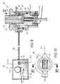
- the electric steering wheel lock 10 has a bolt 11, which is shown in FIG. 1 in its locking position marked by the auxiliary line 11.1 located. In the locking position 11.1, the bolt 11 is out of the housing 12 extended and engages in a non-rotatable recess, not shown Steering column. Then the steering wheel cannot be turned.
- the bar 11 has an extension which is of course movable with the bolt 11 and has a first shoulder 13 on which in this position 11.1 Blocking member 15 is supported. To distinguish similar elements in the area of the motor control 20, this blocking member 15 "Bolt block member” and the shoulder 13 "locking shoulder” are called.
- the locking block member 15 is designed here as an angle lever, which at 14 in Housing 12 is pivotally mounted. A spring load, not shown can ensure that the one angle arm of the locking block member 15 on the Locking shoulder 13 is supported. By one on the locking block member 15 Attacking connection has the consequence that the engine control 20 is not can be operated.
- the motor controller 20 first has an actuator 21, which is in this Embodiment consists of a rotor which is in a fixed stator 22 is rotatably received.
- Rotor 21 and stator 22 are through a circumferential groove 24 and an engaging pin 26 axially connected to each other, as in Fig. 3 can be seen.
- Groove and pin 24, 26 limit the angle of rotation of the rotor, for its manual movement, a rotary handle 27 shown in FIG. 4 is used.
- 1 to 4 show a first starting position of the rotor 21, which in the Cross sections of Fig. 2 to 4 is marked with the auxiliary line 21.1 and below to be referred to as the "rest position" of the actuator 21.
- This rest position 21.1 of the rotor 21 is achieved by a further blocking member 25 secured, which, as already mentioned, with "Actuator block member” should be referred to.
- This also consists in present case from a two-armed lever with angled arms, which is pivotally mounted at 34 in the stator 22.
- the arm ends are in Fig. 1st designated 28, 29.
- the two arm ends 28, 29 are each a control surface 41, 42 assigned, the exact formation from the cross sections of Fig. 2 and 3 that can be seen in the rotor 21 as a circumferential contour in corresponding Axial planes lie and are designed in the following manner.
- the first control surface 41 assigned to the arm end 28 comprises one Radial recess 33 in the rotor 21, which into a via a ramp Circumferential area 23 merges with for reasons that will be seen in more detail later "Work shoulder" should be referred to.
- This Intervention can take place through a positive control, in which the other Arm end 29 is integrated. 1 and 2, the second lies Arm end 29 on a peripheral region 43 of the rotor 21, which to the mentioned heard second control surface 42. This ensures an even more descriptive further forced control of the two blocking elements 15, 25.
- the mechanical connection 30 consists of a Bowden cable whose strand 31 itself is flexible, the two blocking members 15, 25 closely coupled with each other in terms of movement.
- the strand 31 is in one to the Bowden cable belonging jacket 32, the one on the bolt housing 12 and are attached to the stator 22 at another end.
- the strand 31 is both under pressure Can also be operated on a pull and ensures a dimensionally stable, play-free connection of the two blocking elements 15, 25. This has the consequence that the support of the Bolt block member 15 on the locking shoulder 13 via the push-pull strand 31 ensures that the arm end 28 of the actuator block member 25 in the Radial recess 33 is positively locked. Then there is a movement of the Rotor 21 excluded.
- the rotor 21 is part of a switch 40 various movable and stationary contacts 44 to 47. In the rest position 21.1 the electrical connection to the motor is interrupted.
- the bolt 11 in his other, designated by the auxiliary line 11.2 in Fig. 1, dash-dotted indicated release position moved by an electric motor, at the output there is a gear 16. There is a positive connection between this electric motor and the bolt 11 before. In the present case, this applies Gear 16 of the electric motor into a rack 17 provided on the bolt 11 on. What then happens is indicated by dash-dotted lines in FIG. 1.
- the Release position 11.2 the latch 11 is retracted into the housing and gives the also free steering column not shown in FIG. 5. The vehicle can now be directed.
- one Locking recess 19 in alignment with one on the locking block member 15 provided locking end 18. In any case, the locking shoulder 13, like 5 can be seen, moved away and the aforementioned support of the Bolt block member 15 no longer takes place.
- the rotor 21 can be rotated manually. This turning operation is through an arrow 35 in FIG. 8 illustrates.
- the rotor 21 gets into the from 5 to 8 apparent further rotational position, which with the auxiliary line 21.2 is marked and, as already mentioned, referred to as "work situation" shall be.
- switch 40 In the rotatably connected to the rotor 21 switch 40 are now other contacts 44, 47 electrically connected to each other and lead to the desired function in the associated engine of the vehicle, e.g. B. Start or Operation of the engine.
- the other rotary end position is already reached between the pin 26 in the stator and the groove 24 in the rotor 21. While this rotary actuator 35 the following other important processes take place.
- both arm ends 28, 29 with their control surfaces 41, 42 always cooperate positively and in conformity with each other. While the first arm end 28 in the aforementioned rotary actuation 35 from the Radial recess 33 from FIG. 3 via the ramp to its peripheral region 23 opens, the other arm end 29 moves from the peripheral region 43 over one Oblique in a recess 48 of the rotor circumference. This forces one Pivotal movement of the actuator block member 25 about its bearing 34.
- the rotor 21 In order to stop the motor, the rotor 21 has to be turned in via its turning handle 27 The opposite direction in the direction of arrow 36 of Fig. 8 can be rotated. Then it will Actuator block member 25 from its pivot position 25.2 in its through Auxiliary line 25.1 in Fig. 1 clarified position pivoted back. This happens in a mirror image by the forced guidance between the two Control surfaces 41, 42 from the rotor 21 and the arm ends 28, 29 from Actuator block member 25. Except for the bolt 11, which is initially still in its in Fig. 5 visible release position 11.2 remains, via the coupling by means of the connection 30 the locking block member 15 forcibly in his described transferred ineffective position 15.2, which is shown in Fig. 1.
- the rotor 21 shown in the first embodiment has one Receptacle 51 for such a key 50.
- a spring-loaded cover 52 which is pushed back resiliently when the key 50 is inserted.
- the Insertion can be limited by an end stop 53 of the cover 52 in the rotor 21 his.
- a resilient locking means 54 in a locking recess 55 of the Snap in key 50 which is part of a key removal lock.
- This Snap-in movement is possible because, according to FIG. 9, one is in the stator 22 Dodge opening 56 is located in the area of the locking means 54.
- the electronic Key 50 communicates with one located in rotor 21 Transponder coil, which is used to decode the access authorization heard.
- FIGS. 13 to 17 A third embodiment of the invention is shown in FIGS. 13 to 17 and is, as already mentioned in the figure description, only with the help of the here engine controller 20 'of different design is explained.
- Theft protection 10 can, as in the first two exemplary embodiments of FIGS. 1 and 9 be trained.
- the same parts are used to designate the same parts Reference numerals as used in the first embodiment. So far analog Components are designed differently, they should be separated by a dash (') to be marked. It just suffices for the differences and the Add additions to the two previous embodiments. In otherwise, the previous description applies.
- the actuator 21 'as a slide is formed, which acts in the manner of a push button, during the
- the rotor 21 described above worked like a rotary knob.
- the slide 21 ' also has one axial receptacle 51, normally again by a spring-loaded cover 52 is closed.
- the slide 21 ' also has two control surfaces 41', 42 ', which, according to FIG.
- the directional lock 60 initially includes a heart curve 61, which on the Inner surface of the guide 22 'is arranged.
- the heart curve 61 works with one resilient control pin 62 together, the axially fixed via a leaf spring 63 at 68 is connected to the slide 21 '.
- the heart curve 61 has a sawtooth profile, which is why the direction of the movement of the Control pin 62 along the closed heart curve 61 of 15 results. 13, 15 and 17 are drawn in solid lines starting position of the slide 21 'identified by the auxiliary line 62.1.
- the control pin 62 is then located on the first one marked 61.1 in FIG. 17 Station in the area of the heart curve tip.
- a first shoulder 65.1 prevents 15 and 17 the control pin 62 in the "wrong direction" itself move; it can only in the direction of the rising ramp 66.1 of curve 61 from Fig. 17 move, ie in the direction 64 mentioned above the slide 21 'an escape cavity 67, in which, as dashed lines in Fig. 13 and 17 illustrates that the control pin is in its alternative position 62 'together with the spring leaf 63 'can move back.
- the aforementioned position 61.1 corresponded to the contacts 44 'to 47' the "stop" state of the vehicle.
- the slide 21 ' is under the constant action of one from FIG. 13 return spring 37 which can be recognized by a force arrow in FIG. 13 illustrated restoring force 38 exerts on the slide 21 '.
- This is the Slider 21 'strives to reach its rest position 21.1'.
- This also happens after the aforementioned press operation, where the control pin 62 described has reached second position 62.2.
- the control pin goes from position 62.2 by itself its mean axial position marked 62.3 in FIGS. 15 and 17 above and is then located in the curve section labeled 61.3 in FIG. 17, namely a third station, which is located in the area of the central incision of the heart Curve 61 is located.
- An intermediate stable position is reached by the slide 21 ', which corresponds to the "drive" state of the vehicle or its engine.
- the Slider 21 ' is then in its working position 21.2'.
- Anti-theft device 10 differs from the previous exemplary embodiments Anti-theft device 10 ', which is why analog here for naming Components have the same reference numerals as the one described above Anti-theft device 10 are used, however, to distinguish them are provided with a dash (').
- the bilateral blocking members 15, 25 and their common connection 30 are substantially in accordance with the preceding embodiments, which is why in this respect to the previous description can be referenced. It just suffices for that To make differences.
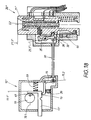
- FIG. 18 shows a situation analogous to FIG. 1.
- the slide 21 ' is located is in its axial rest position 21.1 ', but the key is not yet plugged in.
- the locking block member 15 is in the Locking position 11.1 'of the bolt 11' on a locking shoulder 13 supported and via the connection 30 cause that the Actuator block member 25 is in its operative position 25.1 'where first arm 28 engages in the recess 33 'and thereby the rest position 21.1' of Slider 21 'locked.
- the locking block member 15, in Fig. 18 seen can pivot clockwise, but because of the Support on the locking shoulder 13 is just not possible.
- This pressure actuation 35 ' has been carried out in FIG. 20 and the slide 21' from its rest position 21.1 'indicated by dash-dotted lines there into its Working situation 21.2 'transferred.
- These slide positions are again through the The above-mentioned special directional lock 60 held that in the Connection described in the third embodiment is trained.
- the control pin 62 described is again in its middle position 62.3 in the area of the heart incision there Heart curve 61.
- the slider 21 ' is under the effect of its Restoring force 38, which can not develop now.
- the key 50 is in fixes its insertion position in the slide 21 'because the plunger 71 holds it and the Ram 71 has become immovable. The latter arises because of being Outer end on an inner surface 74 of the slide guide 22 'there supported.
Applications Claiming Priority (2)
| Application Number | Priority Date | Filing Date | Title |
|---|---|---|---|
| DE10233511 | 2002-07-23 | ||
| DE2002133511 DE10233511A1 (de) | 2002-07-23 | 2002-07-23 | Schließsystem für Motorfahrzeuge |
Publications (1)
| Publication Number | Publication Date |
|---|---|
| EP1384633A1 true EP1384633A1 (fr) | 2004-01-28 |
Family
ID=29796541
Family Applications (1)
| Application Number | Title | Priority Date | Filing Date |
|---|---|---|---|
| EP20030014137 Withdrawn EP1384633A1 (fr) | 2002-07-23 | 2003-06-24 | Système de verrouillage pour véhicule à moteur |
Country Status (4)
| Country | Link |
|---|---|
| US (1) | US20050034493A1 (fr) |
| EP (1) | EP1384633A1 (fr) |
| KR (1) | KR20040010346A (fr) |
| DE (1) | DE10233511A1 (fr) |
Cited By (1)
| Publication number | Priority date | Publication date | Assignee | Title |
|---|---|---|---|---|
| EP3243713A1 (fr) * | 2016-05-10 | 2017-11-15 | HUF Hülsbeck & Fürst GmbH & Co. KG | Levier de capteur pour un dispositif de détection d'au moins une position de réglage d'un antivol de direction |
Families Citing this family (22)
| Publication number | Priority date | Publication date | Assignee | Title |
|---|---|---|---|---|
| US7392675B2 (en) * | 2002-11-08 | 2008-07-01 | Kabushiki Kaisha Tokai Rika Denki Seisakusho | Slot mechanism and smart ignition system |
| JP4327571B2 (ja) * | 2003-11-25 | 2009-09-09 | 本田技研工業株式会社 | 鞍乗り型車両 |
| US7140213B2 (en) * | 2004-02-21 | 2006-11-28 | Strattec Security Corporation | Steering column lock apparatus and method |
| DE102004019919B3 (de) * | 2004-04-21 | 2006-02-02 | Huf Hülsbeck & Fürst Gmbh & Co. Kg | Vorrichtung zum Starten eines Fahrzeugmotors mittels eines elektronischen Schlüssels und ein dazu zu verwendener Schlüssel |
| JP2006273115A (ja) * | 2005-03-29 | 2006-10-12 | Alpha Corp | 電動ステアリングロック装置及び電動ステアリングロック装置の制御方法 |
| JP2007023686A (ja) * | 2005-07-20 | 2007-02-01 | Toyota Motor Corp | 解錠制御装置 |
| DE102005035934B4 (de) | 2005-07-28 | 2020-06-04 | Huf Hülsbeck & Fürst Gmbh & Co. Kg | Zünd-Start-Schalter für ein Kraftfahrzeug |
| DE102005038437A1 (de) | 2005-08-12 | 2007-02-15 | Huf Hülsbeck & Fürst GmbH & Co KG | Zündvorrichtung für einen Motor, insbesondere in einem Kraftfahrzeug |
| DE102005050920B4 (de) * | 2005-10-21 | 2017-11-30 | Huf Hülsbeck & Fürst GmbH & Co KG | Verriegelungsvorrichtung |
| CN200984099Y (zh) * | 2005-12-21 | 2007-12-05 | 皇家飞利浦电子股份有限公司 | 制备饮料的筒,饮料制备机和饮料制备系统 |
| US7617708B2 (en) * | 2006-07-28 | 2009-11-17 | Volkswagen Ag | Ignition lock for a motor vehicle and method of operating an ignition lock system |
| US7891221B2 (en) * | 2007-10-01 | 2011-02-22 | Alpha Corporation | Electric steering lock device |
| US7596976B2 (en) * | 2007-11-30 | 2009-10-06 | Alpha Corporation | Electric steering lock device |
| DE102008032585B4 (de) | 2008-07-11 | 2018-07-19 | Huf Hülsbeck & Fürst Gmbh & Co. Kg | Vorrichtung zur Ansteuerung eines Sperrgliedes |
| US8210008B2 (en) * | 2008-08-08 | 2012-07-03 | Lear Corporation | Ignition module with multi-beam spring |
| FR2952005B1 (fr) * | 2009-11-05 | 2016-03-25 | Valeo Securite Habitacle | Dispositif antivol pour colonne de direction de vehicule a super condamnation assuree par bascule |
| FR2965230B1 (fr) * | 2010-09-28 | 2020-02-28 | U-Shin France Sas | Antivol de direction pour vehicule automobile |
| US20150257586A1 (en) * | 2014-03-11 | 2015-09-17 | Starbucks Corporation Dba Starbucks Coffee Company | Single-serve beverage production machine |
| DE102016008561A1 (de) * | 2016-07-14 | 2018-01-18 | Thyssenkrupp Ag | Lenksäule mit elektro-mechanischer Fixiervorrichtung |
| US11339875B2 (en) | 2019-09-23 | 2022-05-24 | Kuster North America, Inc. | Anti-theft and rollaway prevention manual park release mechanism with rotating handle |
| FR3106357B1 (fr) * | 2020-01-16 | 2021-12-10 | Vitesco Technologies | Dispositif d’accès de secours d’ouvrant de véhicule |
| KR102394789B1 (ko) * | 2020-09-15 | 2022-05-04 | 현대제철 주식회사 | 지게차 |
Citations (6)
| Publication number | Priority date | Publication date | Assignee | Title |
|---|---|---|---|---|
| DE19653860C1 (de) * | 1996-12-21 | 1998-02-26 | Valeo Gmbh & Co Schliessyst Kg | Schließsystem für Kraftfahrzeuge |
| EP0893315A2 (fr) * | 1997-07-23 | 1999-01-27 | Toyota Jidosha Kabushiki Kaisha | Système à clé électronique pour véhicules |
| DE19836968A1 (de) * | 1998-08-14 | 2000-02-24 | Huf Huelsbeck & Fuerst Gmbh | Elektrischer Zündanlaßschalter für Motorfahrzeuge |
| EP0999968B1 (fr) | 1997-08-01 | 2001-10-24 | Marquardt GmbH | Blocage de volant de direction sur une automobile |
| US20020023468A1 (en) * | 2000-08-26 | 2002-02-28 | Alexander Frick | Device for locking the streering spindle of a vehicle |
| DE10147031A1 (de) * | 2000-09-27 | 2002-06-27 | Marquardt Gmbh | Zündschloß für ein Kraftfahrzeug |
Family Cites Families (8)
| Publication number | Priority date | Publication date | Assignee | Title |
|---|---|---|---|---|
| US4821605A (en) * | 1988-05-03 | 1989-04-18 | General Motors Corporation | Transmission shift control assembly |
| US5078242A (en) * | 1988-06-13 | 1992-01-07 | United Technologies Automotive, Inc. | Solenoid system for, for example, a brake/shift interlock for vehicular transmission control |
| DE3842332C1 (fr) * | 1988-12-16 | 1989-11-30 | Daimler-Benz Aktiengesellschaft, 7000 Stuttgart, De | |
| JP3449763B2 (ja) * | 1993-11-30 | 2003-09-22 | 富士機工株式会社 | シフトレバー装置 |
| DE4446613B4 (de) * | 1994-12-24 | 2004-04-29 | Marquardt Gmbh | Lenkradverriegelung an einem Kraftfahrzeug |
| DE19509097C1 (de) * | 1995-03-16 | 1996-04-04 | Ymos Ag Ind Produkte | Verriegelungsvorrichtung für Kraftfahrzeuge |
| US5860303A (en) * | 1997-08-29 | 1999-01-19 | Teleflex Incorporated | Ignition safety interlock |
| JP3838630B2 (ja) * | 2002-02-27 | 2006-10-25 | 株式会社ホンダロック | 車両用エンジン始動装置 |
-
2002
- 2002-07-23 DE DE2002133511 patent/DE10233511A1/de not_active Withdrawn
-
2003
- 2003-06-24 EP EP20030014137 patent/EP1384633A1/fr not_active Withdrawn
- 2003-07-23 US US10/626,169 patent/US20050034493A1/en not_active Abandoned
- 2003-07-23 KR KR1020030050476A patent/KR20040010346A/ko not_active Application Discontinuation
Patent Citations (6)
| Publication number | Priority date | Publication date | Assignee | Title |
|---|---|---|---|---|
| DE19653860C1 (de) * | 1996-12-21 | 1998-02-26 | Valeo Gmbh & Co Schliessyst Kg | Schließsystem für Kraftfahrzeuge |
| EP0893315A2 (fr) * | 1997-07-23 | 1999-01-27 | Toyota Jidosha Kabushiki Kaisha | Système à clé électronique pour véhicules |
| EP0999968B1 (fr) | 1997-08-01 | 2001-10-24 | Marquardt GmbH | Blocage de volant de direction sur une automobile |
| DE19836968A1 (de) * | 1998-08-14 | 2000-02-24 | Huf Huelsbeck & Fuerst Gmbh | Elektrischer Zündanlaßschalter für Motorfahrzeuge |
| US20020023468A1 (en) * | 2000-08-26 | 2002-02-28 | Alexander Frick | Device for locking the streering spindle of a vehicle |
| DE10147031A1 (de) * | 2000-09-27 | 2002-06-27 | Marquardt Gmbh | Zündschloß für ein Kraftfahrzeug |
Cited By (1)
| Publication number | Priority date | Publication date | Assignee | Title |
|---|---|---|---|---|
| EP3243713A1 (fr) * | 2016-05-10 | 2017-11-15 | HUF Hülsbeck & Fürst GmbH & Co. KG | Levier de capteur pour un dispositif de détection d'au moins une position de réglage d'un antivol de direction |
Also Published As
| Publication number | Publication date |
|---|---|
| DE10233511A1 (de) | 2004-04-22 |
| US20050034493A1 (en) | 2005-02-17 |
| KR20040010346A (ko) | 2004-01-31 |
Similar Documents
| Publication | Publication Date | Title |
|---|---|---|
| EP1384633A1 (fr) | Système de verrouillage pour véhicule à moteur | |
| DE19939733C2 (de) | Vorrichtung zum Starten eines Fahrzeugmotors mittels eines elektronischen Schlüssels | |
| EP1268959B1 (fr) | Systeme d'acces pour vehicule | |
| EP1110828B1 (fr) | Dispositif de verrouillage | |
| DE19821899C2 (de) | Drehschalter, insbesondere Zündanlaßschalter | |
| EP0907816B1 (fr) | Systeme de fermeture pour portes, capots, clapets ou similaires, notamment dans des vehicules tels que des automobiles | |
| EP1555363B1 (fr) | Dispositif de commande pour portes ou trappes sur véhicules | |
| WO2000051149A1 (fr) | Dispositif pour la reception et le maintien d'un dispositif d'identification, tel qu'une cle electronique, en particulier pour un demarreur a allumage | |
| EP1135284B1 (fr) | Systeme de fermeture, notamment pour automobiles | |
| EP3621855A1 (fr) | Dispositif de verrouillage, en particulier pour un véhicule à moteur | |
| DE102015108664A1 (de) | Schließzylinder mit Rückstellsperre | |
| DE2757544C3 (de) | Lenkschloß für Kraftfahrzeuge | |
| DE10301998B4 (de) | Schließhilfe zum Verschließen einer mit einem Türschloß versehenen Fahrzeugtür | |
| DE3236190C2 (de) | Lenk- und Zündschloß für Kraftfahrzeuge | |
| EP1607289B1 (fr) | Serrure de contact pour véhicule automobile | |
| EP0721869B1 (fr) | Dispositif de verrouillage pour véhicules | |
| DE19921889B4 (de) | Zündschloß für ein Kraftfahrzeug | |
| EP1771322B1 (fr) | Dispositif permettant d'allumer et/ou de demarrer le moteur d'un vehicule automobile | |
| EP1121278B1 (fr) | Dispositif de commande pour l'allumage et le blocage de la direction d'une automobile | |
| DE2925808A1 (de) | Diebstahlsicherung | |
| DE19838992C2 (de) | Zündanlaßschalter für Kraftfahrzeuge mit elektronischer Lenkungsverriegelung | |
| DE69926038T2 (de) | Schloss mit automatischer Entriegelung beim Öffnen | |
| DE19962587C2 (de) | Verriegelungseinrichtung zum Verriegeln der Lenkspindel eines Kraftfahrzeuges | |
| DE1555886C3 (de) | Diebstahlsicherung für Kraftfahrzeuge | |
| DE19903083B4 (de) | Zündschloß für Kraftfahrzeug |
Legal Events
| Date | Code | Title | Description |
|---|---|---|---|
| PUAI | Public reference made under article 153(3) epc to a published international application that has entered the european phase |
Free format text: ORIGINAL CODE: 0009012 |
|
| AK | Designated contracting states |
Kind code of ref document: A1 Designated state(s): AT BE BG CH CY CZ DE DK EE ES FI FR GB GR HU IE IT LI LU MC NL PT RO SE SI SK TR |
|
| AX | Request for extension of the european patent |
Extension state: AL LT LV MK |
|
| 17P | Request for examination filed |
Effective date: 20040526 |
|
| AKX | Designation fees paid |
Designated state(s): DE FR |
|
| 17Q | First examination report despatched |
Effective date: 20041108 |
|
| GRAP | Despatch of communication of intention to grant a patent |
Free format text: ORIGINAL CODE: EPIDOSNIGR1 |
|
| STAA | Information on the status of an ep patent application or granted ep patent |
Free format text: STATUS: THE APPLICATION IS DEEMED TO BE WITHDRAWN |
|
| 18D | Application deemed to be withdrawn |
Effective date: 20080208 |