EP1384633A1 - Locking system for a motor vehicle - Google Patents
Locking system for a motor vehicle Download PDFInfo
- Publication number
- EP1384633A1 EP1384633A1 EP20030014137 EP03014137A EP1384633A1 EP 1384633 A1 EP1384633 A1 EP 1384633A1 EP 20030014137 EP20030014137 EP 20030014137 EP 03014137 A EP03014137 A EP 03014137A EP 1384633 A1 EP1384633 A1 EP 1384633A1
- Authority
- EP
- European Patent Office
- Prior art keywords
- actuator
- bolt
- block member
- locking
- locking system
- Prior art date
- Legal status (The legal status is an assumption and is not a legal conclusion. Google has not performed a legal analysis and makes no representation as to the accuracy of the status listed.)
- Withdrawn
Links
Images


Classifications
-
- B—PERFORMING OPERATIONS; TRANSPORTING
- B60—VEHICLES IN GENERAL
- B60R—VEHICLES, VEHICLE FITTINGS, OR VEHICLE PARTS, NOT OTHERWISE PROVIDED FOR
- B60R25/00—Fittings or systems for preventing or indicating unauthorised use or theft of vehicles
- B60R25/01—Fittings or systems for preventing or indicating unauthorised use or theft of vehicles operating on vehicle systems or fittings, e.g. on doors, seats or windscreens
- B60R25/02—Fittings or systems for preventing or indicating unauthorised use or theft of vehicles operating on vehicle systems or fittings, e.g. on doors, seats or windscreens operating on the steering mechanism
- B60R25/021—Fittings or systems for preventing or indicating unauthorised use or theft of vehicles operating on vehicle systems or fittings, e.g. on doors, seats or windscreens operating on the steering mechanism restraining movement of the steering column or steering wheel hub, e.g. restraining means controlled by ignition switch
- B60R25/0215—Fittings or systems for preventing or indicating unauthorised use or theft of vehicles operating on vehicle systems or fittings, e.g. on doors, seats or windscreens operating on the steering mechanism restraining movement of the steering column or steering wheel hub, e.g. restraining means controlled by ignition switch using electric means, e.g. electric motors or solenoids
- B60R25/02153—Fittings or systems for preventing or indicating unauthorised use or theft of vehicles operating on vehicle systems or fittings, e.g. on doors, seats or windscreens operating on the steering mechanism restraining movement of the steering column or steering wheel hub, e.g. restraining means controlled by ignition switch using electric means, e.g. electric motors or solenoids comprising a locking member radially and linearly moved towards the steering column
-
- B—PERFORMING OPERATIONS; TRANSPORTING
- B60—VEHICLES IN GENERAL
- B60R—VEHICLES, VEHICLE FITTINGS, OR VEHICLE PARTS, NOT OTHERWISE PROVIDED FOR
- B60R25/00—Fittings or systems for preventing or indicating unauthorised use or theft of vehicles
- B60R25/01—Fittings or systems for preventing or indicating unauthorised use or theft of vehicles operating on vehicle systems or fittings, e.g. on doors, seats or windscreens
- B60R25/02—Fittings or systems for preventing or indicating unauthorised use or theft of vehicles operating on vehicle systems or fittings, e.g. on doors, seats or windscreens operating on the steering mechanism
- B60R25/021—Fittings or systems for preventing or indicating unauthorised use or theft of vehicles operating on vehicle systems or fittings, e.g. on doors, seats or windscreens operating on the steering mechanism restraining movement of the steering column or steering wheel hub, e.g. restraining means controlled by ignition switch
- B60R25/02142—Fittings or systems for preventing or indicating unauthorised use or theft of vehicles operating on vehicle systems or fittings, e.g. on doors, seats or windscreens operating on the steering mechanism restraining movement of the steering column or steering wheel hub, e.g. restraining means controlled by ignition switch comprising externally controlled safety devices for preventing locking during vehicle running condition
-
- B—PERFORMING OPERATIONS; TRANSPORTING
- B60—VEHICLES IN GENERAL
- B60R—VEHICLES, VEHICLE FITTINGS, OR VEHICLE PARTS, NOT OTHERWISE PROVIDED FOR
- B60R25/00—Fittings or systems for preventing or indicating unauthorised use or theft of vehicles
- B60R25/01—Fittings or systems for preventing or indicating unauthorised use or theft of vehicles operating on vehicle systems or fittings, e.g. on doors, seats or windscreens
- B60R25/02—Fittings or systems for preventing or indicating unauthorised use or theft of vehicles operating on vehicle systems or fittings, e.g. on doors, seats or windscreens operating on the steering mechanism
- B60R25/021—Fittings or systems for preventing or indicating unauthorised use or theft of vehicles operating on vehicle systems or fittings, e.g. on doors, seats or windscreens operating on the steering mechanism restraining movement of the steering column or steering wheel hub, e.g. restraining means controlled by ignition switch
- B60R25/0215—Fittings or systems for preventing or indicating unauthorised use or theft of vehicles operating on vehicle systems or fittings, e.g. on doors, seats or windscreens operating on the steering mechanism restraining movement of the steering column or steering wheel hub, e.g. restraining means controlled by ignition switch using electric means, e.g. electric motors or solenoids
-
- B—PERFORMING OPERATIONS; TRANSPORTING
- B60—VEHICLES IN GENERAL
- B60R—VEHICLES, VEHICLE FITTINGS, OR VEHICLE PARTS, NOT OTHERWISE PROVIDED FOR
- B60R25/00—Fittings or systems for preventing or indicating unauthorised use or theft of vehicles
- B60R25/01—Fittings or systems for preventing or indicating unauthorised use or theft of vehicles operating on vehicle systems or fittings, e.g. on doors, seats or windscreens
- B60R25/04—Fittings or systems for preventing or indicating unauthorised use or theft of vehicles operating on vehicle systems or fittings, e.g. on doors, seats or windscreens operating on the propulsion system, e.g. engine or drive motor
-
- B—PERFORMING OPERATIONS; TRANSPORTING
- B60—VEHICLES IN GENERAL
- B60R—VEHICLES, VEHICLE FITTINGS, OR VEHICLE PARTS, NOT OTHERWISE PROVIDED FOR
- B60R25/00—Fittings or systems for preventing or indicating unauthorised use or theft of vehicles
- B60R25/20—Means to switch the anti-theft system on or off
- B60R25/2063—Ignition switch geometry
-
- B—PERFORMING OPERATIONS; TRANSPORTING
- B60—VEHICLES IN GENERAL
- B60R—VEHICLES, VEHICLE FITTINGS, OR VEHICLE PARTS, NOT OTHERWISE PROVIDED FOR
- B60R25/00—Fittings or systems for preventing or indicating unauthorised use or theft of vehicles
- B60R25/20—Means to switch the anti-theft system on or off
- B60R25/24—Means to switch the anti-theft system on or off using electronic identifiers containing a code not memorised by the user
- B60R25/248—Electronic key extraction prevention
-
- H—ELECTRICITY
- H01—ELECTRIC ELEMENTS
- H01H—ELECTRIC SWITCHES; RELAYS; SELECTORS; EMERGENCY PROTECTIVE DEVICES
- H01H13/00—Switches having rectilinearly-movable operating part or parts adapted for pushing or pulling in one direction only, e.g. push-button switch
- H01H13/50—Switches having rectilinearly-movable operating part or parts adapted for pushing or pulling in one direction only, e.g. push-button switch having a single operating member
- H01H13/56—Switches having rectilinearly-movable operating part or parts adapted for pushing or pulling in one direction only, e.g. push-button switch having a single operating member the contact returning to its original state upon the next application of operating force
- H01H13/562—Switches having rectilinearly-movable operating part or parts adapted for pushing or pulling in one direction only, e.g. push-button switch having a single operating member the contact returning to its original state upon the next application of operating force making use of a heart shaped cam
-
- Y—GENERAL TAGGING OF NEW TECHNOLOGICAL DEVELOPMENTS; GENERAL TAGGING OF CROSS-SECTIONAL TECHNOLOGIES SPANNING OVER SEVERAL SECTIONS OF THE IPC; TECHNICAL SUBJECTS COVERED BY FORMER USPC CROSS-REFERENCE ART COLLECTIONS [XRACs] AND DIGESTS
- Y10—TECHNICAL SUBJECTS COVERED BY FORMER USPC
- Y10T—TECHNICAL SUBJECTS COVERED BY FORMER US CLASSIFICATION
- Y10T70/00—Locks
- Y10T70/50—Special application
- Y10T70/5611—For control and machine elements
- Y10T70/5646—Rotary shaft
- Y10T70/565—Locked stationary
- Y10T70/5655—Housing-carried lock
- Y10T70/5664—Latching bolt
Definitions
- the invention relates to a locking system in the preamble of Claim 1 specified type.
- the facility used here access authorization can be designed in any manner known per se, e.g. as a so-called "keyless go system” or in the form of electronic or mechanical keys.
- keyless go system for igniting and / or starting one Internal combustion engine in the vehicle or, generally speaking, to control one Any motor is served by an actuator that manually moves to different positions can be triggered and thus triggers different functions on the engine.
- a "rest position” which indicates the parked state of the vehicle, where the engine is resting.
- there are one or more working situations of the Actuator which e.g. the driving condition or the start or start of a Internal combustion engine correspond.
- actuator block member In order to secure the actuator in its rest position, there is a first blocking element provided that to distinguish it from another briefly with “Actuator block member” should be referred to. This actuator block member will set ineffective when addressing the access authorization and then leaves one Movement of the actuator in its working position or working positions.
- the Locking position e.g. acts on the steering of the vehicle or a Operation of the switch for the motor gearbox prevented.
- Theft protection could also result from an interruption in the fuel supply serve an internal combustion engine.
- the bolt To steer or operate the vehicle can, the bolt must be reversed in its release position, which is could be done mechanically, but mostly in modern vehicles an electric motor happens.
- the bolt is also secured in its release position, which is ensured by a second Blockade occurs, which is subsequently used to distinguish it from the aforementioned first blockade link are referred to as "deadbolt block link" should.
- the actuator and the bolt are blocked on the other hand, separate, electrically controllable components are used, for which then further include electronic control parts, namely separate sensors, actuators and the associated control logic.
- electronic control parts namely separate sensors, actuators and the associated control logic.
- there are separate actuators for blocking the actuator on the one hand and the bolt on the other hand which in their workings of the associated control logic can be determined.
- the many electronic components are expensive. With many electrical components, the risk is greater that an electronic component fails and thus the well-known locking system becomes unusable.
- the invention is based, a reliable locking system in the task Developing the preamble of claim 1, which is inexpensive can be manufactured. This is according to the invention by the in claim 1 measures mentioned, which have the following special importance.
- the mechanical connection between the two blocking elements ensures a exact coupling of their reversal movements between their respective effective and ineffective positions regarding the actuator and the latch in a mirror image of each other. If the latch block link is set effectively and secures the bolt in the release position, then the Connection automatically ensures that the actuator block member is in its ineffective position and therefore the actuator between its rest position and his work situation can be moved. If against that Actuator block member is effective and thus the actuator in its rest position secures, then the bolt block member is forcibly via the connection set ineffective. Then the latch is no longer in its release position held and can be motorized or electrical in its locked position be deferred. The reversal movements of the two blocking elements are therefore precisely coordinated.
- All four embodiments of the locking system according to the invention are in the Drawings in two assemblies 10, 20 shown at any distance can be arranged to each other.
- This locking system works with one Access authorization without a key, what is known as a "keyless go system" is.
- the authorized person has a mobile one Identification transmitter with a stationary identification receiver in the vehicle communicated.
- the first assembly is an anti-theft device 10, which in present case consists of an electric steering wheel lock.
- the second Module is a motor controller 20, which in the present case is at a Internal combustion engine is used and therefore as an ignition starter switch is trained.
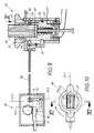
- the electric steering wheel lock 10 has a bolt 11, which is shown in FIG. 1 in its locking position marked by the auxiliary line 11.1 located. In the locking position 11.1, the bolt 11 is out of the housing 12 extended and engages in a non-rotatable recess, not shown Steering column. Then the steering wheel cannot be turned.
- the bar 11 has an extension which is of course movable with the bolt 11 and has a first shoulder 13 on which in this position 11.1 Blocking member 15 is supported. To distinguish similar elements in the area of the motor control 20, this blocking member 15 "Bolt block member” and the shoulder 13 "locking shoulder” are called.
- the locking block member 15 is designed here as an angle lever, which at 14 in Housing 12 is pivotally mounted. A spring load, not shown can ensure that the one angle arm of the locking block member 15 on the Locking shoulder 13 is supported. By one on the locking block member 15 Attacking connection has the consequence that the engine control 20 is not can be operated.
- the motor controller 20 first has an actuator 21, which is in this Embodiment consists of a rotor which is in a fixed stator 22 is rotatably received.
- Rotor 21 and stator 22 are through a circumferential groove 24 and an engaging pin 26 axially connected to each other, as in Fig. 3 can be seen.
- Groove and pin 24, 26 limit the angle of rotation of the rotor, for its manual movement, a rotary handle 27 shown in FIG. 4 is used.
- 1 to 4 show a first starting position of the rotor 21, which in the Cross sections of Fig. 2 to 4 is marked with the auxiliary line 21.1 and below to be referred to as the "rest position" of the actuator 21.
- This rest position 21.1 of the rotor 21 is achieved by a further blocking member 25 secured, which, as already mentioned, with "Actuator block member” should be referred to.
- This also consists in present case from a two-armed lever with angled arms, which is pivotally mounted at 34 in the stator 22.
- the arm ends are in Fig. 1st designated 28, 29.
- the two arm ends 28, 29 are each a control surface 41, 42 assigned, the exact formation from the cross sections of Fig. 2 and 3 that can be seen in the rotor 21 as a circumferential contour in corresponding Axial planes lie and are designed in the following manner.
- the first control surface 41 assigned to the arm end 28 comprises one Radial recess 33 in the rotor 21, which into a via a ramp Circumferential area 23 merges with for reasons that will be seen in more detail later "Work shoulder" should be referred to.
- This Intervention can take place through a positive control, in which the other Arm end 29 is integrated. 1 and 2, the second lies Arm end 29 on a peripheral region 43 of the rotor 21, which to the mentioned heard second control surface 42. This ensures an even more descriptive further forced control of the two blocking elements 15, 25.
- the mechanical connection 30 consists of a Bowden cable whose strand 31 itself is flexible, the two blocking members 15, 25 closely coupled with each other in terms of movement.
- the strand 31 is in one to the Bowden cable belonging jacket 32, the one on the bolt housing 12 and are attached to the stator 22 at another end.
- the strand 31 is both under pressure Can also be operated on a pull and ensures a dimensionally stable, play-free connection of the two blocking elements 15, 25. This has the consequence that the support of the Bolt block member 15 on the locking shoulder 13 via the push-pull strand 31 ensures that the arm end 28 of the actuator block member 25 in the Radial recess 33 is positively locked. Then there is a movement of the Rotor 21 excluded.
- the rotor 21 is part of a switch 40 various movable and stationary contacts 44 to 47. In the rest position 21.1 the electrical connection to the motor is interrupted.
- the bolt 11 in his other, designated by the auxiliary line 11.2 in Fig. 1, dash-dotted indicated release position moved by an electric motor, at the output there is a gear 16. There is a positive connection between this electric motor and the bolt 11 before. In the present case, this applies Gear 16 of the electric motor into a rack 17 provided on the bolt 11 on. What then happens is indicated by dash-dotted lines in FIG. 1.
- the Release position 11.2 the latch 11 is retracted into the housing and gives the also free steering column not shown in FIG. 5. The vehicle can now be directed.
- one Locking recess 19 in alignment with one on the locking block member 15 provided locking end 18. In any case, the locking shoulder 13, like 5 can be seen, moved away and the aforementioned support of the Bolt block member 15 no longer takes place.
- the rotor 21 can be rotated manually. This turning operation is through an arrow 35 in FIG. 8 illustrates.
- the rotor 21 gets into the from 5 to 8 apparent further rotational position, which with the auxiliary line 21.2 is marked and, as already mentioned, referred to as "work situation" shall be.
- switch 40 In the rotatably connected to the rotor 21 switch 40 are now other contacts 44, 47 electrically connected to each other and lead to the desired function in the associated engine of the vehicle, e.g. B. Start or Operation of the engine.
- the other rotary end position is already reached between the pin 26 in the stator and the groove 24 in the rotor 21. While this rotary actuator 35 the following other important processes take place.
- both arm ends 28, 29 with their control surfaces 41, 42 always cooperate positively and in conformity with each other. While the first arm end 28 in the aforementioned rotary actuation 35 from the Radial recess 33 from FIG. 3 via the ramp to its peripheral region 23 opens, the other arm end 29 moves from the peripheral region 43 over one Oblique in a recess 48 of the rotor circumference. This forces one Pivotal movement of the actuator block member 25 about its bearing 34.
- the rotor 21 In order to stop the motor, the rotor 21 has to be turned in via its turning handle 27 The opposite direction in the direction of arrow 36 of Fig. 8 can be rotated. Then it will Actuator block member 25 from its pivot position 25.2 in its through Auxiliary line 25.1 in Fig. 1 clarified position pivoted back. This happens in a mirror image by the forced guidance between the two Control surfaces 41, 42 from the rotor 21 and the arm ends 28, 29 from Actuator block member 25. Except for the bolt 11, which is initially still in its in Fig. 5 visible release position 11.2 remains, via the coupling by means of the connection 30 the locking block member 15 forcibly in his described transferred ineffective position 15.2, which is shown in Fig. 1.
- the rotor 21 shown in the first embodiment has one Receptacle 51 for such a key 50.
- a spring-loaded cover 52 which is pushed back resiliently when the key 50 is inserted.
- the Insertion can be limited by an end stop 53 of the cover 52 in the rotor 21 his.
- a resilient locking means 54 in a locking recess 55 of the Snap in key 50 which is part of a key removal lock.
- This Snap-in movement is possible because, according to FIG. 9, one is in the stator 22 Dodge opening 56 is located in the area of the locking means 54.
- the electronic Key 50 communicates with one located in rotor 21 Transponder coil, which is used to decode the access authorization heard.
- FIGS. 13 to 17 A third embodiment of the invention is shown in FIGS. 13 to 17 and is, as already mentioned in the figure description, only with the help of the here engine controller 20 'of different design is explained.
- Theft protection 10 can, as in the first two exemplary embodiments of FIGS. 1 and 9 be trained.
- the same parts are used to designate the same parts Reference numerals as used in the first embodiment. So far analog Components are designed differently, they should be separated by a dash (') to be marked. It just suffices for the differences and the Add additions to the two previous embodiments. In otherwise, the previous description applies.
- the actuator 21 'as a slide is formed, which acts in the manner of a push button, during the
- the rotor 21 described above worked like a rotary knob.
- the slide 21 ' also has one axial receptacle 51, normally again by a spring-loaded cover 52 is closed.
- the slide 21 ' also has two control surfaces 41', 42 ', which, according to FIG.
- the directional lock 60 initially includes a heart curve 61, which on the Inner surface of the guide 22 'is arranged.
- the heart curve 61 works with one resilient control pin 62 together, the axially fixed via a leaf spring 63 at 68 is connected to the slide 21 '.
- the heart curve 61 has a sawtooth profile, which is why the direction of the movement of the Control pin 62 along the closed heart curve 61 of 15 results. 13, 15 and 17 are drawn in solid lines starting position of the slide 21 'identified by the auxiliary line 62.1.
- the control pin 62 is then located on the first one marked 61.1 in FIG. 17 Station in the area of the heart curve tip.
- a first shoulder 65.1 prevents 15 and 17 the control pin 62 in the "wrong direction" itself move; it can only in the direction of the rising ramp 66.1 of curve 61 from Fig. 17 move, ie in the direction 64 mentioned above the slide 21 'an escape cavity 67, in which, as dashed lines in Fig. 13 and 17 illustrates that the control pin is in its alternative position 62 'together with the spring leaf 63 'can move back.
- the aforementioned position 61.1 corresponded to the contacts 44 'to 47' the "stop" state of the vehicle.
- the slide 21 ' is under the constant action of one from FIG. 13 return spring 37 which can be recognized by a force arrow in FIG. 13 illustrated restoring force 38 exerts on the slide 21 '.
- This is the Slider 21 'strives to reach its rest position 21.1'.
- This also happens after the aforementioned press operation, where the control pin 62 described has reached second position 62.2.
- the control pin goes from position 62.2 by itself its mean axial position marked 62.3 in FIGS. 15 and 17 above and is then located in the curve section labeled 61.3 in FIG. 17, namely a third station, which is located in the area of the central incision of the heart Curve 61 is located.
- An intermediate stable position is reached by the slide 21 ', which corresponds to the "drive" state of the vehicle or its engine.
- the Slider 21 ' is then in its working position 21.2'.
- Anti-theft device 10 differs from the previous exemplary embodiments Anti-theft device 10 ', which is why analog here for naming Components have the same reference numerals as the one described above Anti-theft device 10 are used, however, to distinguish them are provided with a dash (').
- the bilateral blocking members 15, 25 and their common connection 30 are substantially in accordance with the preceding embodiments, which is why in this respect to the previous description can be referenced. It just suffices for that To make differences.
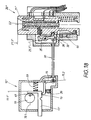
- FIG. 18 shows a situation analogous to FIG. 1.
- the slide 21 ' is located is in its axial rest position 21.1 ', but the key is not yet plugged in.
- the locking block member 15 is in the Locking position 11.1 'of the bolt 11' on a locking shoulder 13 supported and via the connection 30 cause that the Actuator block member 25 is in its operative position 25.1 'where first arm 28 engages in the recess 33 'and thereby the rest position 21.1' of Slider 21 'locked.
- the locking block member 15, in Fig. 18 seen can pivot clockwise, but because of the Support on the locking shoulder 13 is just not possible.
- This pressure actuation 35 ' has been carried out in FIG. 20 and the slide 21' from its rest position 21.1 'indicated by dash-dotted lines there into its Working situation 21.2 'transferred.
- These slide positions are again through the The above-mentioned special directional lock 60 held that in the Connection described in the third embodiment is trained.
- the control pin 62 described is again in its middle position 62.3 in the area of the heart incision there Heart curve 61.
- the slider 21 ' is under the effect of its Restoring force 38, which can not develop now.
- the key 50 is in fixes its insertion position in the slide 21 'because the plunger 71 holds it and the Ram 71 has become immovable. The latter arises because of being Outer end on an inner surface 74 of the slide guide 22 'there supported.
Abstract
Description
Die Erfindung richtet sich auf ein Schließsystem der im Oberbegriff des Anspruches 1 angegebenen Art. Die dabei zur Anwendung kommende Einrichtung zur Zugangsberechtigung kann in jeder an sich bekannten Weise ausgebildet sein, z.B. als sogenanntes "keyless-go-system" oder in Form von elektronischen oder mechanischen Schlüsseln. Zum Zünden und/oder Anlassen eines Verbrennungsmotors im Fahrzeug oder, allgemein gesagt, zum Steuern eines beliebigen Motors dient ein Betätiger, der manuell in verschiedene Lagen bewegt werden kann und dadurch unterschiedliche Funktionen am Motor auslöst. In jedem Fall gibt es eine "Ruhelage", welche den Parkzustand des Fahrzeugs kennzeichnet, wo der Motor ruht. Darüber hinaus gibt es eine oder mehrere Arbeitslagen des Betätigers, die z.B. dem Fahrtzustand oder dem Start- bzw. Anlassen eines Verbrennungsmotors entsprechen.The invention relates to a locking system in the preamble of Claim 1 specified type. The facility used here access authorization can be designed in any manner known per se, e.g. as a so-called "keyless go system" or in the form of electronic or mechanical keys. For igniting and / or starting one Internal combustion engine in the vehicle or, generally speaking, to control one Any motor is served by an actuator that manually moves to different positions can be triggered and thus triggers different functions on the engine. In each Case there is a "rest position" which indicates the parked state of the vehicle, where the engine is resting. In addition, there are one or more working situations of the Actuator which e.g. the driving condition or the start or start of a Internal combustion engine correspond.
Um den Betätiger in seiner Ruhelage zu sichern, ist ein erstes Blockadeglied vorgesehen, das zur Unterscheidung von einem weiteren kurz mit "Betätigerblockglied" bezeichnet werden soll. Dieses Betätigerblockglied wird beim Ansprechen-der Zugangsberechtigung unwirksam gesetzt und lässt dann eine Bewegung des Betätigers in dessen Arbeitslage bzw. Arbeitslagen zu.In order to secure the actuator in its rest position, there is a first blocking element provided that to distinguish it from another briefly with "Actuator block member" should be referred to. This actuator block member will set ineffective when addressing the access authorization and then leaves one Movement of the actuator in its working position or working positions.
Zur Diebstahlssicherung des Fahrzeugs ist ein zwischen zwei Stellungen umsteuerbarer Riegel vorgesehen, der in seiner einen Stellung, nämlich der Verriegelungsstellung, z.B. auf die Lenkung des Fahrzeugs einwirkt oder eine Betätigung der Schalthandhabe für das Motor-Getriebe verhindert. Die Diebstahlssicherung könnte auch aus einer Unterbrechung der Kraftstoffzufuhr zu einem Verbrennungsmotor dienen. Um das Fahrzeug lenken oder betreiben zu können, muss der Riegel in seine Freigabestellung umgesteuert werden, was zwar mechanisch erfolgen könnte, aber bei modernen Fahrzeugen überwiegend mittels eines Elektromotors geschieht.To protect the vehicle from theft, there is one between two positions reversible bolt provided in its one position, namely the Locking position, e.g. acts on the steering of the vehicle or a Operation of the switch for the motor gearbox prevented. The Theft protection could also result from an interruption in the fuel supply serve an internal combustion engine. To steer or operate the vehicle can, the bolt must be reversed in its release position, which is could be done mechanically, but mostly in modern vehicles an electric motor happens.
Auch der Riegel wird in seiner Freigabestellung gesichert, was durch ein zweites Blockadeglied geschieht, welches nachfolgend zur Unterscheidung von dem vorgenannten ersten Blockadeglied mit "Riegelblockglied" bezeichnet werden soll.The bolt is also secured in its release position, which is ensured by a second Blockade occurs, which is subsequently used to distinguish it from the aforementioned first blockade link are referred to as "deadbolt block link" should.
Bei einem bekannten Schließsystem dieser Art (EP 0 999 968 B1) wird eine elektromagnetische Sperre als Riegelblockglied benutzt. Diese elektromagnetische Sperre wird aber zugleich als Betätigerblockglied zur Sicherung der Ruhelage des Betätigers verwendet. Wenn die elektromagnetische Sperre versagt, sind bei diesem bekannten Schließsystem gleichzeitig zwei Elemente des Schließsystems nicht mehr gesichert, nämlich sowohl der Betätiger als auch der Riegel, was verhängnisvolle Folgen haben kann.In a known locking system of this type (EP 0 999 968 B1) a electromagnetic lock used as a bolt block member. This electromagnetic Lock is also used as an actuator block to secure the rest of the Actuator used. If the electromagnetic lock fails, are at this known locking system simultaneously two elements of the locking system no longer secured, namely both the actuator and the bolt, what can have disastrous consequences.
Normalerweise werden zur Blockade des Betätigers einerseits und des Riegels andererseits getrennte elektrisch steuerbare Bauteile genutzt, wozu dann weitere elektronische Steuerteile gehören, nämlich getrennte Sensoren, Aktuatoren und die zugehörige Steuerlogik. Man benutzte nämlich nicht nur Sensoren, welche die Ruhelage und die diversen Arbeitslagen des Betätigers erkennen und unterscheiden müssen, sondern auch Sensoren um die Freigabestellung und die Verriegelungsstellung des Riegels festzustellen und der Steuerlogik zu melden. Schließlich sind, wie gesagt, getrennte Aktuatoren zur Blockade des Betätigers einerseits und des Riegels andererseits erforderlich, die in ihrer Arbeitsweise von der zugehörigen Steuerlogik bestimmt werden. Die vielen elektronischen Bauteile sind kostenaufwendig. Bei vielen elektrischen Bauteilen ist die Gefahr größer, dass ein elektronischer Bauteil versagt und damit das bekannte Schließsystem unbrauchbar wird. Usually, the actuator and the bolt are blocked on the other hand, separate, electrically controllable components are used, for which then further include electronic control parts, namely separate sensors, actuators and the associated control logic. You didn't just use sensors that Recognize the rest position and the various working positions of the actuator and must distinguish, but also sensors around the release position and the Determine the locking position of the bolt and report it to the control logic. Finally, as I said, there are separate actuators for blocking the actuator on the one hand and the bolt on the other hand, which in their workings of the associated control logic can be determined. The many electronic components are expensive. With many electrical components, the risk is greater that an electronic component fails and thus the well-known locking system becomes unusable.
Der Erfindung liegt die Aufgabe zugrunde, ein zuverlässiges Schließsystem der im Oberbegriff von Anspruch 1 genannten Art zu entwickeln, welches preiswert hergestellt werden kann. Dies wird erfindungsgemäß durch die im Anspruch 1 genannten Maßnahmen erreicht, denen folgende besondere Bedeutung zukommt.The invention is based, a reliable locking system in the task Developing the preamble of claim 1, which is inexpensive can be manufactured. This is according to the invention by the in claim 1 measures mentioned, which have the following special importance.
Die mechanische Verbindung zwischen den beiden Blockadegliedern sorgt für eine exakte Koppelung ihrer Umsteuerungsbewegungen zwischen ihren jeweiligen wirksamen und unwirksamen Positionen bezüglich des Betätigers und des Riegels und zwar in zueinander spiegelbildlicher Weise. Wenn das Riegelblockglied wirksam gesetzt ist und den Riegel in der Freigabestellung sichert, dann sorgt die Verbindung automatisch dafür, dass sich das Betätigerblockglied in seiner unwirksamen Position befindet und daher der Betätiger zwischen seiner Ruhelage und seinen Arbeitslagen bewegt werden kann. Wenn dagegen das Betätigerblockglied wirksam ist und damit den Betätiger in seiner Ruhelage sichert, dann wird über die Verbindung das Riegelblockglied zwangsweise unwirksam gesetzt. Dann wird der Riegel nicht mehr in seiner Freigabestellung gehalten und kann motorisch oder elektrisch in seine Verriegelungsstellung zurückgestellt werden. Die Umsteuerungsbewegungen der beiden Blockadeglieder sind also exakt aufeinander abgestimmt.The mechanical connection between the two blocking elements ensures a exact coupling of their reversal movements between their respective effective and ineffective positions regarding the actuator and the latch in a mirror image of each other. If the latch block link is set effectively and secures the bolt in the release position, then the Connection automatically ensures that the actuator block member is in its ineffective position and therefore the actuator between its rest position and his work situation can be moved. If against that Actuator block member is effective and thus the actuator in its rest position secures, then the bolt block member is forcibly via the connection set ineffective. Then the latch is no longer in its release position held and can be motorized or electrical in its locked position be deferred. The reversal movements of the two blocking elements are therefore precisely coordinated.
Darüber hinaus kann über die Verbindung mindestens die wirksame Position des Betätigerblockglieds in der Ruhelage des Betätigers durch das Riegelblockglied arretiert sein. Dazu genügt es, das Riegelblockglied in der Verriegelungsstellung des Riegels an einer Schulter sich abstützen zu lassen, weil diese Abstützwirkung über die Verbindung die vorerwähnte Arretierung des Betätigerblockglieds gegenüber dem Betätiger zur Folge hat. Diese Schulter, die mit "Verriegelungsschulter" bezeichnet werden soll, ist bei der Umsteuerung des Riegels mitbeweglich und im einfachsten Fall Bestandteil des Riegels. Damit sind Fehlbedienungen der Blockadeglieder beim erfindungsgemäßen Schließsystem ausgeschlossen. In addition, at least the effective position of the Actuator block link in the rest position of the actuator through the locking block link be locked. To do this, it is sufficient to have the locking block member in the locking position of the latch on one shoulder to be supported because of this supporting effect the above-mentioned locking of the actuator block member via the connection towards the actuator. That shoulder that with "Locking shoulder" is to be referred to is in the reversal of the Bolt movable and in the simplest case part of the bolt. With that Incorrect operation of the blocking elements in the locking system according to the invention locked out.
Durch diese Kopplung der beidseitigen Blockadeglieder lassen sich Sensoren an mindestens einem der miteinander zu verbindenden Endelemente sparen, z.B. diejenigen, die zur Erkennung der Stellung des Riegels normalerweise erforderlich sind. In jedem Fall werden aber Aktuatoren bei den erfindungsgemäß miteinander gekoppelten Blockadegliedern eingespart.This coupling of the blocking elements on both sides allows sensors to be connected save at least one of the end elements to be connected, e.g. those normally required to detect the position of the latch are. In any case, however, actuators are used with each other according to the invention coupled blockade members saved.
Weitere Maßnahmen und Vorteile der Erfindung ergeben sich aus den Unteransprüchen, der nachfolgenden Beschreibung und den Zeichnungen. In den Zeichnungen ist die Erfindung in mehreren Ausführungsbeispielen dargestellt. Es zeigen:
- Fig. 1,
- schematisch und im Längsschnitt, ein erstes Schließsystem mit einem Betätiger und einem Riegel nach der Erfindung, welches ohne Schlüssel arbeitet, was als "keyless-go-system" bezeichnet wird, und zwar in einer ersten Arbeitsphase, nämlich in der Ruhelage des Betätigers einerseits in der Verriegelungsstellung des Riegels andererseits,
- Fig. 2 + 3
- Querschnitte durch den in Fig. 1 gezeigten Betätiger längs der dortigen Schnittlinien II - II bzw. III - III,
- Fig. 4
- die Draufsicht auf den Betätiger von Fig. 1 in Blickrichtung des Pfeils IV,
- Fig. 5
- eine andere Betriebsphase des in Fig. 1 gezeigten ersten Ausführungsbeispiels, wo sich der Betätiger in seiner Arbeitslage und der Riegel in seiner Freigabelage befindet,
- Fig. 6, 7, 8,
- in Analogie zu Fig. 2, 3 und 4 die Querschnitte bzw. die Draufsichten auf den Betätiger von Fig. 5 längs der dortigen Schnittlinien VI - VI bzw. VII - VII bzw. in Blickrichtung des Pfeils VIII,
- Fig. 9
- ein zweites Ausführungsbeispiel der Erfindung und zwar in einer der Fig. 1 entsprechenden Darstellung und Position,
- Fig. 10,
- in Analogie zu Fig. 4, die Draufsicht auf den in Fig. 9 gezeigten Betätiger,
- Fig. 11
- das zweite Ausführungsbeispiel von Fig. 9, wenn sich die Bauteile in der aus Fig. 5 erkennbaren Position befinden,
- Fig. 12,
- in Analogie zu Fig. 6, einen Querschnitt durch den in Fig. 11 gezeigten Betätiger längs der dortigen Schnittlinie XII - XII,
- Fig. 13
- von einem dritten Ausführungsbeispiel der Erfindung im Längsschnitt nur den zugehörigen Betätiger, wenn sich dieser in seiner Ruhelage befindet, die derjenigen des ersten Ausführungsbeispiels von Fig. 1 entspricht, wobei der Riegel, der nicht näher gezeigt ist, die aus Fig. 1 ersichtliche Bauweise aufweisen kann,
- Fig. 14
- eine Draufsicht auf den in Fig. 13 gezeigten Betätiger in Blickrichtung des Pfeils XIV von Fig. 13,
- Fig. 15
- ein senkrecht zum Längsschnitt von Fig. 13 ausgeführter weiterer Längsschnitt durch den in Fig. 13 gezeigten Betätiger längs der versprungenen Schnittlinie XV - XV von Fig. 13,
- Fig. 16
- ein Detail des in Fig. 13 gezeigten Betätigers, wenn sich dieser in seiner anderen Betriebsphase befindet, nämlich der Arbeitslage, was der in Fig. 5 gezeigten Betriebsphase des ersten Ausführungsbeispiels entspricht, , wobei der zugehörige Riegel entsprechend Fig. 5 des ersten Ausführungsbeispiels ausgebildet sein kann,
- Fig. 17
- eine ebene Abwickelung einer am Betätiger von Fig. 13 vorgesehenen Steuerkurve, deren Draufsicht in Fig. 15 zu sehen ist,
- Fig. 18,
- in einer der Fig. 1 entsprechenden Darstellung und Betriebsphase, ein viertes Ausführungsbeispiel der Erfindung,
- Fig. 19,
- das Ausführungsbeispiel von Fig. 18 in einer weiteren Betriebsphase, wenn ein elektronischer Schlüssel in den Betätiger gesteckt worden ist, der Betätiger selbst aber sich noch in seiner mit Fig. 18 übereinstimmenden Ruhelage befindet und
- Fig. 20
- das vierte Ausführungsbeispiel in einer dritten Betriebsphase, welche derjenigen von Fig. 5 des ersten Ausführungsbeispiels entspricht.
- Fig. 1
- schematically and in longitudinal section, a first locking system with an actuator and a bolt according to the invention, which works without a key, which is referred to as a "keyless go system", in a first working phase, namely in the rest position of the actuator on the one hand in the locking position of the bolt on the other hand,
- Fig. 2 + 3
- Cross sections through the actuator shown in Fig. 1 along the section lines II - II and III - III,
- Fig. 4
- the top view of the actuator of Fig. 1 in the direction of arrow IV,
- Fig. 5
- another operating phase of the first exemplary embodiment shown in FIG. 1, where the actuator is in its working position and the latch is in its release position,
- 6, 7, 8,
- analogous to FIGS. 2, 3 and 4, the cross sections or the plan views of the actuator of FIG. 5 along the section lines VI - VI or VII - VII there or in the direction of arrow VIII,
- Fig. 9
- 2 shows a second exemplary embodiment of the invention, namely in a representation and position corresponding to FIG. 1,
- Fig. 10,
- in analogy to FIG. 4, the top view of the actuator shown in FIG. 9,
- Fig. 11
- the second embodiment of FIG. 9, when the components are in the position shown in FIG. 5,
- Fig. 12
- in analogy to FIG. 6, a cross section through the actuator shown in FIG. 11 along the section line XII-XII there,
- Fig. 13
- of a third embodiment of the invention in longitudinal section only the associated actuator when it is in its rest position, which corresponds to that of the first embodiment of Fig. 1, the bolt, which is not shown in detail, have the construction shown in Fig. 1 can
- Fig. 14
- 13 shows a top view of the actuator shown in FIG. 13 in the direction of arrow XIV of FIG. 13,
- Fig. 15
- 13 shows a further longitudinal section perpendicular to the longitudinal section of FIG. 13 through the actuator shown in FIG. 13 along the jumped section line XV-XV of FIG. 13,
- Fig. 16
- a detail of the actuator shown in Fig. 13 when it is in its other operating phase, namely the working position, which corresponds to the operating phase shown in Fig. 5 of the first embodiment, the associated bolt being designed according to Fig. 5 of the first embodiment can
- Fig. 17
- a flat development of a control curve provided on the actuator of FIG. 13, the top view of which can be seen in FIG. 15,
- Fig. 18
- in a representation and operating phase corresponding to FIG. 1, a fourth exemplary embodiment of the invention,
- Fig. 19,
- the embodiment of FIG. 18 in a further operating phase when an electronic key has been inserted into the actuator, but the actuator itself is still in its rest position corresponding to FIG. 18 and
- Fig. 20
- the fourth embodiment in a third operating phase, which corresponds to that of FIG. 5 of the first embodiment.
Alle vier Ausführungsbeispiele des erfindungsgemäßen Schließsystems sind in den
Zeichnungen in zwei Baugruppen 10, 20 dargestellt die in beliebigem Abstand
zueinander angeordnet sein können. Dieses Schließsystem arbeitet mit einer
Zugangsberechtigung ohne einen Schlüssel, was als "keyless-go-system" bekannt
ist. In diesem Fall besitzt die berechtigte Person einen mobilen
Identifikationsgeber, der mit einem stationären Identifikationsnehmer im Fahrzeug
kommuniziert. Die erste Baugruppe ist eine Diebstahlssicherung 10, die im
vorliegenden Fall aus einer elektrischen Lenkradverriegelung besteht. Die zweite
Baugruppe ist eine Motorsteuerung 20, die im vorliegenden Fall bei einem
Verbrennungsmotor angewendet wird und daher als Zündanlassschalter
ausgebildet ist. All four embodiments of the locking system according to the invention are in the
Drawings in two
Die elektrische Lenkradverriegelung 10 besitzt einen Riegel 11, der sich in Fig. 1
in seiner durch die Hilfslinie 11.1 gekennzeichneten Verriegelungsstellung
befindet. In der Verriegelungsstellung 11.1 ist der Riegel 11 aus dem Gehäuse 12
ausgefahren und greift in eine nicht näher gezeigte drehfeste Ausnehmung einer
Lenkradsäule ein. Dann ist die Drehung des Lenkrads nicht möglich. Der Riegel
11 hat eine Verlängerung die mit dem Riegel 11 natürlich mitbeweglich ist und
eine erste Schulter 13 aufweist, an welcher in dieser Stellung 11.1 ein
Blockadeglied 15 sich abstützt. Zwecks Unterscheidung von ähnlichen Elementen
im Bereich der Motorsteuerung 20 soll dieses Blockadeglied 15
"Riegelblockglied" und die Schulter 13 "Verriegelungsschulter" genannt werden.
Das Riegelblockglied 15 ist hier als Winkelhebel ausgebildet, der bei 14 im
Gehäuse 12 schwenkbar gelagert ist. Eine nicht näher gezeigte Federbelastung
kann dafür sorgen, dass der eine Winkelarm des Riegelblockglieds 15 an der
Verriegelungsschulter 13 sich abstützt. Durch eine am Riegelblockglied 15
angreifende Verbindung hat dies zur Folge, dass die Motorsteuerung 20 nicht
betätigt werden kann.The electric
Die Motorsteuerung 20 besitzt zunächst einen Betätiger 21, der in diesem
Ausführungsbeispiel aus einem Rotor besteht, welcher in einem ortsfesten Stator
22 drehbar aufgenommen ist. Rotor 21 und Stator 22 sind durch eine Umfangsnut
24 und einen darin eingreifenden Stift 26 miteinander axialfest verbunden, wie aus
Fig. 3 zu ersehen ist. Nut und Stift 24, 26 begrenzen den Drehwinkel des Rotors,
zu dessen manueller Bewegung eine aus Fig. 4 erkennbare Drehhandhabe 27 dient.
Fig. 1 bis 4 zeigen eine erste Ausgangslage des Rotors 21, die in den
Querschnitten von Fig. 2 bis 4 mit der Hilfslinie 21.1 markiert ist und nachfolgend
als "Ruhelage" des Betätigers 21 bezeichnet werden soll.The
Diese Ruhelage 21.1 des Rotors 21 wird durch ein weiteres Blockadeglied 25
gesichert, welches nachfolgend, wie bereits erwähnt wurde, mit
"Betätigerblockglied" bezeichnet werden soll. Auch dieses besteht im
vorliegenden Fall aus einem zweiarmigen Hebel mit abgewinkelten Armen,
welcher bei 34 im Stator 22 schwenkbar gelagert ist. Die Armenden sind in Fig. 1
mit 28, 29 bezeichnet. Den beiden Armenden 28, 29 sind jeweils eine Steuerfläche
41, 42 zugeordnet, deren genaue Ausbildung aus den Querschnitten von Fig. 2 und
3 zu erkennen ist, die beim Rotor 21 als Umfangskontur in entsprechenden
Axialebenen liegen und in folgender Weise ausgebildet sind.This rest position 21.1 of the
Die dem Armende 28 zugeordnete erste Steuerfläche 41 umfasst eine
Radialaussparung 33 im Rotor 21, welche über eine Rampe in einen
Umfangsbereich 23 übergeht, der aus später noch näher ersichtlichen Gründen mit
"Arbeitsschulter" bezeichnet werden soll. In der Ruhelage 21.1 gemäß Fig. 1 und
3 greift das eine Armende 28 gerade in die Radialaussparung 33 ein. Dieser
Eingriff kann durch eine Zwangssteuerung erfolgen, in welche das andere
Armende 29 integriert ist. Wie aus Fig. 1 und 2 hervorgeht, liegt das zweite
Armende 29 an einem Umfangsbereich 43 des Rotors 21 an, der zu der erwähnten
zweiten Steuerfläche 42 gehört. Das sorgt für eine noch näher zu beschreibende
weitere Zwangssteuerung der beiden Blockadeglieder 15, 25.The first control surface 41 assigned to the
Im vorliegenden Fall besteht die mechanische Verbindung 30 aus einem
Bowdenzug dessen an sich flexibler Strang 31 die beiden Blockadeglieder 15, 25
miteinander bewegungsmäßig eng koppelt. Der Strang 31 befindet sich in einem
zum Bowdenzug gehörenden Mantel 32, der am Riegelgehäuse 12 einerends und
am Stator 22 andererends befestigt sind. Der Strang 31 ist sowohl auf Druck als
auch auf Zug betätigbar und sorgt für eine formfeste, spielfreie Verbindung der
beiden Blockadeglieder 15, 25. Das hat zur Folge, dass die Abstützung des
Riegelblockglieds 15 an der Verriegelungsschulter 13 über den Druck-Zug-Strang
31 dafür sorgt, dass das Armende 28 vom Betätigerblockglied 25 in der
Radialaussparung 33 formschlüssig arretiert ist. Dann ist eine Bewegung des
Rotors 21 ausgeschlossen. Der Rotor 21 ist Bestandteil eines Schalters 40 mit
diversen beweglichen und ruhenden Kontakten 44 bis 47. In der Ruhelage 21.1 ist
die elektrische Verbindung zum Motor unterbrochen.In the present case, the
Wenn die hier als "keyless-go" ausgebildete Zugangsberechtigung erkennt, dass
der berechtigte Benutzer das Fahrzeug starten möchte, so wird der Riegel 11 in
seine andere mit der Hilfslinie 11.2 in Fig. 1 bezeichnete, strichpunktiert
angedeutete Freigabestellung über einen Elektromotor bewegt, an dessen Ausgang
sich ein Zahnrad 16 befindet. Es liegt eine formschlüssige Verbindung zwischen
diesem Elektromotor und dem Riegel 11 vor. Im vorliegenden Fall greift das
Zahnrad 16 des Elektromotors in eine am Riegel 11 vorgesehene Zahnstange 17
ein. Was dann passiert, ist strichpunktiert in Fig. 1 angedeutet. In der
Freigabestellung 11.2 ist der Riegel 11 in das Gehäuse eingefahren und gibt die
auch in Fig. 5 nicht näher gezeigte Lenksäule frei. Das Fahrzeug kann jetzt
gelenkt werden. Dann ist, wie strichpunktiert in Fig. 1 verdeutlicht ist, eine
Sperrausnehmung 19 in Ausrichtung mit einem am Riegelblockglied 15
vorgesehenen Sperrende 18. In jedem Fall ist die Verriegelungsschulter 13, wie
aus Fig. 5 zu ersehen ist, weggefahren und die vorerwähnte Abstützung des
Riegelblockglieds 15 findet nicht mehr statt.If the access authorization trained here as "keyless-go" recognizes that
the authorized user wants to start the vehicle, the
Dann kann der Rotor 21 manuell gedreht werden. Diese Drehbetätigung ist durch
einen Pfeil 35 in Fig. 8 veranschaulicht. Dabei gelangt der Rotor 21 in die aus den
Fig. 5 bis 8 ersichtliche weitere Drehlage, welche mit der Hilfslinie 21.2
gekennzeichnet ist und, wie bereits erwähnt wurde, mit "Arbeitslage" bezeichnet
werden soll. Im drehfest mit dem Rotor 21 verbundenen Schalter 40 sind jetzt
andere Kontakte 44, 47 miteinander elektrisch verbunden und führen zu der
gewünschten Funktion im zugehörigen Motor des Fahrzeugs, z. B. Start oder
Betrieb des Motors. Im vorliegenden Fall ist bereits die andere Dreh-Endstellung
zwischen dem Stift 26 im Stator und der Nut 24 im Rotor 21 erreicht. Während
dieser Drehbetätigung 35 laufen folgende weiteren wichtigen Vorgänge ab.Then the
Es liegt, wie bereits erwähnt wurde, eine Zwangssteuerung des
Betätigerblockglieds 25 vor, weil beide Armenden 28, 29 mit ihren Steuerflächen
41, 42 stets formschlüssig und konform zueinander zusammenwirken. Während
das erste Armende 28 bei der vorerwähnten Drehbetätigung 35 aus der
Radialaussparung 33 von Fig. 3 über die Rampe auf seinen Umfangsbereich 23
auffährt, bewegt sich das andere Armende 29 vom Umfangsbereich 43 über eine
Schräge in eine Ausnehmung 48 des Rotor-Umfangs. Dieser zwingt eine
Schwenkbewegung des Betätigerblockglieds 25 um dessen Lager 34.As already mentioned, there is a forced control of the
Dieses Umschwenken des Betätigerblockglieds 25 hat zur Folge, dass über die
genannte mechanische Verbindung 30 das andere Riegelblockglied 15
zwangsweise mitverschwenkt wird und in die aus Fig. 5 ersichtliche andere
Schwenkposition gelangt. Diese Position ist in Fig. 5 durch die Hilfslinie 15.1
gekennzeichnet und erweist sich als "wirksame Position" des Riegelblockglieds
15. Dann ist nämlich sein Sperrende 18 in die Sperrausnehmung 19 des Riegels 11
eingeschwenkt und blockiert somit den Riegel 11 in dessen aus Fig. 5
ersichtlichen Freigabestellung 11.2. Die vorausgehende, in Fig. 1 gezeigte
Schwenkstellung des Riegelblockglieds 15 ist durch die Hilfslinie 15.2
gekennzeichnet, die dann die "unwirksame Position" des Riegelblockglieds 15
kennzeichnet.This pivoting of the
Bei dem erfindungsgemäßen Schließsystem ist die aus Fig. 5 erkennbare und mit
der Hilfslinie 25.2 gekennzeichnete Schwenkposition vom Betätigerblockglied 25
Ursache dafür, dass über die formfeste Verbindung 30 das Riegelblockglied 15
sich in der genannten wirksamen Position 15.1 gegenüber dem Riegel 11 befindet.
Es findet eine Arretierung statt. Das Riegelblockglied 15 kann nicht in die
unwirksame Position von Fig. 1 überführt werden. Ursache dafür ist, dass sich das
am anderen Ende der Verbindung 30 befindliche Betätigerblockglied 25, wie Fig.
5 zeigt, mit seinem Armende 28 in Abstützung an der zu seiner Steuerfläche 41
gehörenden Arbeitsschulter 23 befindet, was besonders gut aus Fig. 7 zu
entnehmen ist.In the locking system according to the invention, the one shown in FIG
the auxiliary line 25.2 marked pivot position of the
Um den Motor zu stoppen, muss der Rotor 21 über seine Drehhandhabe 27 in
Gegenrichtung im Sinne des Pfeils 36 von Fig. 8 gedreht werden. Dann wird das
Betätigerblockglied 25 aus seiner Schwenkposition 25.2 in seine durch die
Hilfslinie 25.1 in Fig. 1 verdeutlichte Position zurückgeschwenkt. Dies geschieht
in spiegelbildlicher Weise durch die Zwangsführung zwischen den beiden
Steuerflächen 41, 42 vom Rotor 21 und den Armenden 28, 29 vom
Betätigerblockglied 25. Bis auf den Riegel 11, der zunächst noch in seiner aus Fig.
5 ersichtlichen Freigabestellung 11.2 verbleibt, wird über die Kopplung mittels
der Verbindung 30 das Riegelblockglied 15 zwangsweise in seine beschriebene
unwirksame Position 15.2 überführt, die in Fig. 1 gezeigt ist. Dann ist sein
Sperrende 18 außer Eingriff mit der Sperrausnehmung 19. Der Riegel 11 könnte
dann über den erwähnten Elektromotor wieder zurückbewegt werden. Dies
geschieht aber zweckmäßigerweise erst dann, wenn bestimmte weitere
Betriebsbedingungen am Fahrzeug erfüllt sind. Dazu gehören, einzelweise
und/oder in Kombination, dass das Fahrzeug tatsächlich steht, und/oder dass der
Motor aus ist, und/oder dass die Tür fahrseitig geöffnet wird, und/oder dass ein
Taster betätigt wird, und/oder der Türgriff betätigt wird. Weil in der
Schwenkposition 25.1 das Betätigerblockglied 25 die Drehung des Rotors 21
ausschließt, kann diese Position als "wirksame Position" bezeichnet werden.
Damit erweist sich die andere mit 25.2 in Fig. 5 bezeichnete Schwenkposition als
die "unwirksame Position" des Betätigerblockglieds 25.In order to stop the motor, the
Im zweiten Ausführungsbeispiel von Fig. 9 bis 12 ist das Schließsystem analog ausgebildet, weshalb insoweit die bisherige Beschreibung gilt. Der Unterschied gegenüber dem vorausgehenden Ausführungsbeispiel besteht darin, dass angenommen wird, das vorausgehend beschriebene "keyles-go-system" sei ausgefallen, was z.B. durch äußere elektromagnetische Felder verursacht sein kann. Dann kann aber das Fahrzeug mittels des aus Fig. 9 bis 11 gezeigten Notschlüssels 50 in analoger Weise betätigt werden. Das geschieht in folgender Weise.In the second exemplary embodiment from FIGS. 9 to 12, the locking system is analog trained, which is why the description so far applies. The difference compared to the previous embodiment is that it is assumed that the "keyles go system" described above is failed, e.g. be caused by external electromagnetic fields can. Then, however, the vehicle can be operated by means of the one shown in FIGS Emergency key 50 are operated in an analogous manner. This happens in the following Wise.
Der im ersten Ausführungsbeispiel gezeigte Rotor 21 besitzt nämlich eine
Aufnahme 51 für einen solchen Schlüssel 50. Normalerweise ist die Aufnahme 51,
wie aus Fig. 1 zu erkennen ist, von einem federbelasteten Deckel 52 verschlossen,
der beim Einstecken des Schlüssels 50 federnd zurückgedrückt wird. Das
Einstecken kann durch einen Endanschlag 53 des Deckels 52 im Rotor 21 begrenzt
sein. Dann kann ein federndes Rastmittel 54 in eine Rastausnehmung 55 des
Schlüssels 50 einschnappen, die zu einer Schlüssel-Abzugssicherung gehört. Diese
Einschnappbewegung ist möglich, weil, gemäß Fig. 9, im Stator 22 sich eine
Ausweichöffnung 56 im Bereich des Rastmittels 54 befindet. Der elektronische
Schlüssel 50 kommuniziert dabei mit einer im Rotor 21 befindlichen
Transponderspule, welche zu den Decodiermitteln der Zugangsberechtigung
gehört. Ist die Decodierung erfolgreich, so wird der Riegel 11 in die in Fig. 9
strichpunktiert angedeutete Freigabestellung 11.2 überführt. Dann ist das
Riegelblockglied 15 nicht mehr an der Verriegelungsschulter 13 abgestützt, wie
bereits im Zusammenhang mit dem ersten Ausführungsbeispiel beschrieben wurde.
Ferner ist über die besondere Verbindung 30 auch das Betätigerblockglied 25
unwirksam gesetzt und lässt eine Drehung des Rotors 21, z. B. über den
elektronischen Schlüssel 50 zu. Es kommt daher wieder zu der vorbeschriebenen
Verschwenkung des Betätigerblockglieds 25 in seine beschriebene unwirksame
Position 25.2 von Fig. 11 und 12. Die gekuppelte Baugruppe aus Schlüssel 50 und
Betätiger 21 befindet sich dann in der bereits oben beschriebenen Arbeits-Drehlage
21.2. Diese Arbeitslage ist in Fig. 12 gezeigt. Dann ist nicht nur, wie
schon beim ersten Ausführungsbeispiel im Zusammenhang mit Fig. 5 beschrieben
wurde, das Riegelblockglied 15 in seiner wirksamen Schwenkposition 15.1 von
Fig. 11, sondern auch das Herausziehen des Schlüssels 50 ist gemäß Fig. 12
blockiert. Das Rastmittel 54 der Schlüsselabzugssicherung ist nämlich in seiner
Rastausnehmung 55 gesichert, weil es sich radial an der Innenfläche des Rotors 22
abstützt und nicht mehr mit der Ausweichöffnung 56 im Stator 22 radial
ausgerichtet ist. Erst wenn die gekuppelte Baugruppe aus Schlüssel 50 und Rotor
21 wieder in ihre aus Fig. 9 und 10 ersichtliche Ruhelage 21.1 zurückgedreht
worden ist, ist ein Herausziehen des Schlüssels 50 möglich.The
Ein drittes Ausführungsbeispiel der Erfindung ist in den Fig. 13 bis 17 gezeigt und
wird, wie bereits bei der Figurbeschreibung erwähnt wurde, nur anhand der hier
abweichend ausgebildeten Motorsteuerung 20' erläutert. Die Diebstahlssicherung
10 kann so wie in den beiden ersten Ausführungsbeispielen von Fig. 1 bzw. 9
ausgebildet sein. Zur Bezeichnung gleicher Teile werden die gleichen
Bezugszeichen wie im ersten Ausführungsbeispiel verwendet. Soweit analoge
Bauteile aber abweichend ausgebildet sind, sollen sie durch einen Strich (')
gekennzeichnet sein. Es genügt lediglich auf die Unterschiede und die
Ergänzungen der beiden vorausgehenden Ausführungsbeispiele einzugehen. In
übriger Hinsicht gilt die bisherige Beschreibung.A third embodiment of the invention is shown in FIGS. 13 to 17 and
is, as already mentioned in the figure description, only with the help of the here
engine controller 20 'of different design is explained.
Der wesentliche Unterschied besteht darin, dass hier der Betätiger 21' als Schieber
ausgebildet ist, der nach Art eines Druckknopfs wirkt, während der
vorbeschriebene Rotor 21 wie ein Drehknopf arbeitete. Auch in diesem Fall kann
die Betätigung, in Analogie zu Fig. 1 bis 8, durch ein "keyless-go-system" ohne
Schlüssel, oder, in Analogie zu Fig. 9 bis 12, mit einem strichpunktiert
angedeuteten Schlüssel (50) erfolgen. Deswegen besitzt der Schieber 21' auch eine
axiale Aufnahme 51, die normalerweise wieder durch einen federbelasteten Deckel
52 verschlossen ist. Auch der Schieber 21' besitzt zwei Steuerflächen 41', 42',
welche, gemäß Fig. 16, zwar als Längskontur ausgebildet sind, aber in analoger
Weise mit den beiden Armenden 28, 29 des auch hier hebelartig ausgebildeten
Betätigerblockglieds 25 zusammenwirken. Dieses Betätigerblockglied 25 ist jetzt
in dem Gehäuse einer Führung 22' integriert, welche den Schieber 21'
längsverschieblich im Sinne des Pfeils 35' von Fig. 13 bzw. 16 aufnimmt. Eine
entsprechende Längsorientierung gilt natürlich auch hinsichtlich der in Fig. 13
erkennbaren analogen Kontakte 44', 45', 46' und 47' des integrierten Zünd-Anlass-Schalters.The main difference is that here the actuator 21 'as a slide
is formed, which acts in the manner of a push button, during the
The
Die Fig. 13 zeigt die Ruhelage 21.1' des Schiebers 21'. Dann greift das eine
Armende 28 des Betätigerblockglieds 25 in eine Aussparung 33' in einer
definierten Höhe des Schiebers 21' ein, während sich sein zweites Armende 29 an
einer Längskante 43' vom Schieber 21' abstützt und dadurch auch hier die bereits
im ersten Ausführungsbeispiel beschriebene wirksame Schwenkposition 25.1'
bewirkt. Dann befindet sich die Diebstahlssicherung 10, wie in der analogen Fig. 1
gezeigt ist, mit ihrem Riegelblockglied 15 in einer Abstützposition ihres
Riegelblockglieds 15 bei 13, 18, wodurch auch im vorliegenden Fall über die
formfeste, z.B. aus Bowdenzug ausgebildete Verbindung 30 die wirksame Position
25.1' des Schiebers 21' arretiert ist. 13 shows the rest position 21.1 'of the slide 21'. Then one thing takes hold
Arm end 28 of the
Erst wenn durch die bereits oben beschriebenen Maßnahmen der Elektromotor den
Riegel 11 in seine aus Fig. 5 des ersten Ausführungsbeispiels ersichtliche
Freigabestellung 11.2 überführt hat, ist auch bei diesem dritten
Ausführungsbeispiel die erwähnte Längsbetätigung 35' des Schiebers 21' möglich.
Diese eingedrückte Position ist in Fig. 16 dargestellt. Der Schieber befindet sich
dann in der mit 21.2' gekennzeichneten eingedrückten Arbeitslage. Durch
geeignete, aufeinander abgestimmte Profilierung der in den beiden Steuerflächen
41', 42' von Fig. 16 erkennbaren Auflauf- und Ablaufschrägen fährt das erste
Armende 28 vom Betätigerblockglied 25 auf die Längskante 23' vom Schieber
21', während der zweite Arm 29 in eine Ausnehmung 48' an definierter axialer
Stelle vom Schieber 21 zurückweichen kann. Dadurch gelangt das
Betätigerblockglied 25 in seine unwirksame Schwenkposition 25.2' von Fig. 16,
wodurch über den Strang 31 der Verbindung 30 das zugehörige Riegelblockglied
15, in Analogie zu Fig. 5, in seine aus Fig. 5 ersichtliche wirksame Position 15.1
übergeht. Die Arbeitslage 21.2' des Schiebers 21' von Fig. 16 ist durch ein
besonderes Richtgesperre 60 gesichert, dessen Ausbildung anhand der Fig. 13, 15
und einer ebenen Kurven-Abwickelung von Fig. 17 zu erkennen ist.Only when the electric motor takes the measures already described above
Zum Richtgesperre 60 gehört zunächst eine Herzkurve 61, welche an der
Innenfläche der Führung 22' angeordnet ist. Die Herzkurve 61 wirkt mit einem
federnden Steuerstift 62 zusammen, der über eine Blattfeder 63 bei 68 axialfest
mit dem Schieber 21' verbunden ist. Die Herzkurve 61 besitzt ein Sägezahn-Profil,
weshalb der durch den Pfeil 64 verdeutlichte Richtungssinn der Bewegung des
Steuerstifts 62 entlang der in sich ringförmig geschlossenen Herzkurve 61 von
Fig. 15 sich ergibt. Ausgezogen gezeichnet sind in den Fig. 13, 15 und 17 eine
durch die Hilfslinie 62.1 gekennzeichnete Ausgangsposition des Schiebers 21'.
Der Steuerstift 62 befindet sich dann an der in Fig. 17 mit 61.1 markierten ersten
Station im Bereich der Herzkurven-Spitze. Wenn man jetzt den Schieber 21' im
Sinne des Pfeils 35' druckbetätigt, dann hindert eine erste Schulter 65.1 gemäß
Fig. 15 und 17 den Steuerstift 62 daran, in die "falsche Richtung" sich zu
bewegen; er kann nur in Richtung der ansteigenden Rampe 66.1 der Kurve 61 von
Fig. 17 sich bewegen, also in dem vorerwähnten Richtungssinn 64. Dazu besitzt
der Schieber 21' eine Ausweichhöhle 67, in welche, wie gestrichelt in Fig. 13 und
17 verdeutlicht ist, der Steuerstift sich in seine Ausweichlage 62' zusammen mit
dem Federblatt 63' zurückbewegen kann.The
Die vorerwähnte Position 61.1 entsprach, bezogen auf die Kontakte 44' bis 47' dem Zustand "Halt" des Fahrzeugs. Bei der Druckbetätigung 35' gelangt der Schieber zunächst in seine mit 62.2 in Fig. 15 gekennzeichnete tiefste Position hinter einer aus Fig. 17 erkennbaren zweiten Schulter 65.2, was seiner zweiten Station an der in Fig. 15 linken Herzflanke entspricht. Bezogen auf die Kontakte 44' bis 47' kann diese Position 62.2 dem Zustand "Start" des Fahrzeugs bzw. dessen Motors entsprechen.The aforementioned position 61.1 corresponded to the contacts 44 'to 47' the "stop" state of the vehicle. When pressing 35 'the First slide into its lowest position marked 62.2 in FIG. 15 behind a second shoulder 65.2 which can be seen in FIG 15 on the left flank of the heart. Based on the contacts 44 'to 47' this position 62.2 can correspond to the "start" state of the vehicle or whose engine correspond.
Der Schieber 21' steht unter der beständigen Wirkung einer aus Fig. 13
erkennbaren Rückstellfeder 37, welche eine durch einen Kraftpfeil in Fig. 13
verdeutlichte Rückstellkraft 38 auf den Schieber 21' ausübt. Dadurch ist der
Schieber 21' bestrebt in seine Ruhelage 21.1' zu gelangen. Dies geschieht auch
nach der vorerwähnten Druckbetätigung, wo der Steuerstift 62 die beschriebene
zweite Position 62.2 erreicht hat. Wird dann kein manueller Druck auf den
Schieber 21' ausgeübt, so geht der Steuerstift aus der Position 62.2 von selbst in
seine in Fig. 15 und 17 mit 62.3 gekennzeichnete mittlere Axialposition über und
befindet sich dann in dem mit 61.3 in Fig. 17 gekennzeichneten Kurvenstück,
nämlich einer dritten Station, die sich im Bereich des mittigen Herzeinschnitts der
Kurve 61 befindet. Es ist eine zwischenstabile Position vom Schieber 21' erreicht,
welche dem Zustand "Fahrt" des Fahrzeugs bzw. seines Motors entspricht. Der
Schieber 21' befindet sich dann in seiner Arbeitslage 21.2'.The slide 21 'is under the constant action of one from FIG. 13
Weil auch die dritte Station 61.3 in Rückrichtung durch die aus Fig. 17 erkennbare
dritte Schulter 65.3 gesperrt ist, ist bei einer weiteren Druckbetätigung wieder nur
eine Bewegung in Richtung der aus Fig. 17 erkennbaren dritten Rampe 66.3 im
Sinne des Pfeils 64 von Fig. 15 möglich. Es kommt erneut zu einer tiefsten
Position 62.4 der Steuerkurve 61 hinter einer vierten Schulter 65.4. Dann ist eine
vierte Station im Bereich der rechten Herzflanke von Fig. 15 erreicht, die in Fig.
17 mit 61.4 gekennzeichnet ist. Diese vierte Station ist aber nicht stabil, weil sich
an der vierten Station 61.4 sogleich die im Entspannungssinne der Feder 37
weisende vierte Rampe 66.4 gemäß Fig. 17 anschließt. Wenn die manuelle
Druckausübung auf den Schieber 21' nachlässt, wird der Schieber 21 automatisch
durch die erwähnte Rückstellkraft 38 weiterbewegt. Der Schieber 21' gelangt also
dann automatisch, ohne Zwischenhalt, in seine oberste Position 62.1 an der Station
61.1 im Bereich der Herzspitze. Der Schieber 21' befindet sich dann wieder in
seiner Ruhelage 21.1'.Because also the third station 61.3 in the backward direction by the one shown in FIG
third shoulder 65.3 is locked, is again only with a further pressure actuation
a movement in the direction of the third ramp 66.3 in FIG
Possible sense of
Bei einer Steuerung über den bereits erwähnten Schlüssel 50 lässt sich auch in
diesem dritten Ausführungsbeispiel der Schlüssel nur in der Ruhelage 21.1' des
Schiebers 21' einstecken oder abziehen. Das wird wieder über ein federndes
Rastmittel 54' einer Abzugssicherung erreicht, welches über eine Blattfeder 57'
axialfest mit dem Schieber 21' verbunden ist und durch eine Öffnung ins Innere
der Schlüsselaufnahme 51 hineinragt. Im Falle einer Schlüsselbenutzung rastet
dieses Rastmittel 54' in analoger Weise in eine Rastausnehmung des Schlüssels 50
ein, wie es in Fig. 9 gezeigt ist. Dieses Rastmittel 54' ist, wie Fig. 15 verdeutlicht,
ebenfalls nur dann mit einer Ausweichöffnung 56' ausgerichtet, wenn die dortige
Ruhelage 21.1' vorliegt. Nach der Druckbetätigung 35' von Fig. 16 hat sich das
Rastmittel 54' mit dem Schieber 21' axial von der Ausweichöffnung 56' entfernt
und stützt sich an der in Fig. 15 mit 58 gekennzeichneten Innenfläche 58 der
Schieberführung 22' ab.In the case of control via the key 50 already mentioned, in
this third embodiment, the key only in the rest position 21.1 'of
Insert or remove slide 21 '. That will be about a springy again
Latching means 54 'of a trigger safety device is reached, which via a leaf spring 57'
is axially fixed to the slide 21 'and through an opening into the interior
the
In den Fig. 18 bis 20 ist ein viertes Ausführungsbeispiel der Erfindung dargestellt,
die nur mit einem einzusteckenden elektronischen Schlüssel 50 zusammenwirkt. In
diesem Fall ist die Motorsteuerung 20' weitgehend derjenigen des
vorbeschriebenen dritten Ausführungsbeispiels von Fig. 13 bis 17 ähnlich,
weshalb insoweit die bisherige Beschreibung gilt. Es liegt also auch in diesem Fall
ein druckbetätigbarer Schieber 21' vor, der allerdings nur mit dem richtigen
Schlüssel 50 betätigt werden kann. Die nachfolgend erläuterten Abwandlungen
können sinngemäß aber auch bei einem drehbetätigbaren Rotor 21 gemäß den
beiden ersten Ausführungsbeispielen von Fig. 1 bis 12 angewendet werden. 18 to 20 show a fourth embodiment of the invention,
which only interacts with an electronic key 50 to be inserted. In
In this case, the engine control 20 'is largely that of the
13 to 17 similar to the previously described third exemplary embodiment,
which is why the description so far applies. So it is also in this case
a push-actuable slide 21 'in front, but only with the correct one
Unterschiedlich gegenüber den vorausgehenden Ausführungsbeispielen ist aber die
Diebstahlssicherung 10' ausgebildet, weshalb hier zur Benennung analoger
Bauteile zwar die gleichen Bezugszeichen wie bei der vorbeschriebenen
Diebstahlssicherung 10 benutzt werden, allerdings zu deren Unterscheidung mit
einem Strich (') versehen sind. Die beidseitigen Blockadeglieder 15, 25 und ihre
gemeinsame Verbindung 30 sind im wesentlichen in Übereinstimmung mit den
vorausgehenden Ausführungsbeispielen ausgebildet, weshalb insoweit auf die
vorausgehende Beschreibung verwiesen werden kann. Es genügt lediglich auf die
Unterschiede einzugehen.However, it differs from the previous exemplary embodiments
Anti-theft device 10 ', which is why analog here for naming
Components have the same reference numerals as the one described above
Die Fig. 18 zeigt einen zu Fig. 1 analogen Sachverhalt. Der Schieber 21' befindet
sich zwar in seiner axialen Ruhelage 21.1', doch ist der Schlüssel noch nicht
eingesteckt. Auch in diesem Fall ist das Riegelblockglied 15 in der
Verriegelungsstellung 11.1' des Riegels 11' an einer Verriegelungsschulter 13
abgestützt und über die Verbindung 30 Ursache dafür, dass das
Betätigerblockglied 25 sich in seiner wirksamen Position 25.1' befindet, wo sein
erster Arm 28 in die Aussparung 33' eingreift und dadurch die Ruhelage 21.1' des
Schiebers 21' arretiert. Das gilt, obwohl das Riegelblockglied 15, welches sich in
Fig. 18 in seiner unwirksamen Position 15.2 befindet, in Richtung seiner
wirksamen Position durch eine Rückstellfeder 39 kraftbelastet ist. Um in seine
wirksame Position 15.1 zu gelangen, müsste sich das Riegelblockglied 15, in Fig.
18 gesehen, im Uhrzeigersinn verschwenken können, was aber wegen der
Abstützung an der Verriegelungsschulter 13 gerade nicht möglich ist.FIG. 18 shows a situation analogous to FIG. 1. The slide 21 'is located
is in its axial rest position 21.1 ', but the key is not yet
plugged in. In this case, too, the locking
Wenn der Schlüssel 50 gemäß Fig. 19 in die Aufnahme 51 des Schiebers 51'
eingesteckt wird, wird durch Wechselwirkung mit dem Transponder 49 die
Zugangsberechtigungs-Einrichtung den richtigen Schlüssel 50 als zugehörig
identifizieren und einen Elektromotor veranlassen, einen Exzenter 70 so
umzusteuern, dass der Riegel 11' gegen die Wirkung einer Riegel-Rückstellfeder
59 den Riegel 11' in seine aus Fig. 19 ersichtliche Freigabestellung 11.2'
überführt. Dann ist aber das Sperrende 18 des Riegelblockglieds 15 in Ausrichtung
mit einer Sperrausnehmung 19 vom Riegel 11', in welche er durch seine
Rückstellfeder 39 hineingedrückt wird. Das Riegelblockglied 15 gelangt dann in
seine wirksame Position 15.1 und nimmt über die Verbindung 30 das
Betätigerblockglied 25 mit. Dadurch gelangt dieses aus der bis dahin vorliegenden
wirksamen Position 25.1', die in Fig. 19 strichpunktiert angedeutet ist, in seine
unwirksame, ausgezogen gezeichnete Position 25.2'. Dann ist, wie Fig. 19 zeigt,
das Armende 28 außerhalb der Aussparung 33' und lässt daher eine
Druckbetätigung des Schiebers 21' zu. Gleichzeitig findet eine Verrastung
zwischen dem Schlüssel 50 und dem Schieber 21' statt. Dafür sorgt ein Stößel 71,
welcher durch eine Stößelfeder 72 bestrebt ist, in eine Rastausnehmung 55 des
Schlüssels 50 einzufahren. Der Stößel 71 hat einen Ansatz 73, in welchem nicht
nur die Stößelfeder 72 angreift, sondern der zugleich als Endanschlag zur
Begrenzung der Längsbewegung des Stößels 71 dient. In Fig. 19 ist eine
Druckbetätigung des Schiebers 21' möglich.19 when the key 50 in the
Diese Druckbetätigung 35' ist in Fig. 20 ausgeführt worden und der Schieber 21'
aus seiner dort noch strichpunktiert angedeuteten Ruhelage 21.1' in seine
Arbeitslage 21.2' überführt. Diese Schieber-Lagen werden wieder durch das
vorbeschriebene besondere Richtgesperre 60 gehalten, dass in der im
Zusammenhang mit dem dritten Ausführungsbeispiel beschriebenen Weise
ausgebildet ist. In Fig. 20 befindet sich der beschriebene Steuerstift 62 wieder in
seiner mittleren Position 62.3 im Bereich des Herzeinschnitts der dortigen
Herzkurve 61. Der Schieber 21' steht zwar unter der Wirkung seiner
Rückstellkraft 38, die aber sich jetzt nicht entfalten kann. Der Schlüssel 50 ist in
seiner Einstecklage im Schieber 21' fixiert, weil ihn der Stößel 71 festhält und der
Stößel 71 unverschieblich geworden ist. Letzteres ergibt sich, weil sein
Außenende sich an einer Innenfläche 74 der dortigen Schieber-Führung 22'
abstützt.This pressure actuation 35 'has been carried out in FIG. 20 and the slide 21'
from its rest position 21.1 'indicated by dash-dotted lines there into its
Working situation 21.2 'transferred. These slide positions are again through the
The above-mentioned special
Bedeutsam ist wieder die besondere Arretierung des Riegelblockglieds 15. Der
Riegel 11' wird in seiner Freigabestellung 11.2' durch das an der Motorsteuerung
20' vorgesehene Betätigerblockglied 25 gesichert. Letzteres 25 befindet sich bei
Fig. 20 immer noch in der bereits in Fig. 19 beschriebenen unwirksamen Position
25.2'. Diese unwirksame Position 25.2' ist aber in Fig. 20 gesichert, weil sich sein
erstes Armende 28 an seiner Längskontur 23' abstützt. Dadurch ist eine im
Gegenuhrzeigersinn von Fig. 20 erforderliche Umschwenkbewegung des
Betätigerblockglieds 25 in seine dort strichpunktiert angedeutete wirksame
Position nicht möglich. Über die Verbindung 30 ist daher auch im Bereich der
Diebstahlssicherung 10' eine solche im Gegenuhrzeigersinn wirksame
Schwenkbewegung des Riegelblockglieds 15 aus dessen dortigen ausgezogen
gezeichneten wirksamen Position 15.1 in die strichpunktiert veranschaulichte
unwirksame Position 15.2 nicht möglich.Again, the special locking of the
Durch erneute Druckbetätigung der aus Schlüssel 50 und Schieber 21' bestehenden
Baugruppe wird über die vorbeschriebene Herzkurve 61 des Richtgesperres 60
wieder die Ruhelage 21.1' von Fig. 19 erreicht. Über die nicht näher gezeigte
Steuerelektronik kann dann der Elektromotor den Exzenter 70 aus seiner zunächst
noch bestehenden, ausgezogen gezeichneten, durch eine Hilfslinie 70.2 markierten
Einschub-Drehlage in die in Fig. 19 bereits strichpunktiert verdeutlichte
gegensinnige Ausschub-Drehlage zurückbewegen, welche, in Übereinstimmung
mit Fig. 19, mit der Hilfslinie 70.1 markiert ist. Dabei kann der Elektromotor den
Exzenter 70 im gleichen Drehsinn 69 wie im vorausgehenden Fall zwischen Fig.
18 und 19 weiterdrehen. Dann ist zwar die Riegel-Rückstellfeder 59 bestrebt den
Riegel 11' aus der Freigabestellung 11.2' wieder zurückzubewegen, doch ist das
nicht möglich, weil zunächst das Riegelblockglied 15 mit seinem Sperrende 18
immer noch in die Sperrausnehmung 19 des Riegels 11' eingreift.By pressing the key 50 and slide 21 'again
Assembly is via the
Die Freigabestellung 11.2' bleibt solange erhalten, bis der Schlüssel 50 aus dem
Schieber 21' abgezogen worden ist. Gemäß Fig. 19 stützt sich nämlich der Stößel
71 an dem zweiten Armende 29 des Betätigerblockglieds 25 ab, ist aber nicht
mehr, wie in Fig. 20, gesperrt. Der Schlüssel kann daher im Sinne des
Bewegungspfeils 25 von Fig. 19 aus dem Schieber 21' herausgezogen werden.
Dabei fährt das innere Ende des Stößels 71 aus der schlüsselseitigen
Rastausnehmung 55 heraus und bewirkt eine Längsbewegung des Stößels 71 gegen
dessen Stößelfeder 72. Diese ist ja in Fig. 19 möglich, weil das erste Armende 28
des Betätigerblockglieds 25 wieder mit der Aussparung 33' an der Längskante des
Schiebers 21' ausgerichtet ist. Durch diese Längsbewegung des Stößels 71 wird
nicht nur das Betätigungsglied 25 in seine in Fig. 19 strichpunktiert angedeutete
wirksame Position 25.1' zurückgeschwenkt, sondern, über die Verbindung 30,
gelangt auch das Riegelblockglied 15 in seine unwirksame Position 15.2. Dann
fährt das Sperrende 18 aus der Sperrausnehmung 19 vom Riegel 11' heraus und
der Riegel 11' kann durch die Riegel-Rückstellfeder 59 wieder in seine
strichpunktiert in Fig. 19 gezeigte Verriegelungslage 11.1' gegenüber einer nicht
näher gezeigten Lenksäule gelangen. Dann liegen wieder die Verhältnisse von Fig.
18 vor. The release position 11.2 'remains until the key 50 from the
Slider 21 'has been removed. 19 namely the plunger is supported
71 from the
- 1010
- Diebstahlssicherung, elektrische Lenkradverriegelung (Fig. 1 bis 17)Anti-theft device, electric steering wheel lock (Fig. 1 to 17)
- 10'10 '
- alternative Diebstahlssicherung (Fig. 18 bis 20)alternative theft protection (Fig. 18 to 20)
- 1111
- Riegel für 10 (Fig. 1 bis 17)Latch for 10 (Fig. 1 to 17)
- 11'11 '
- Riegel für 10' (Fig. 18 bis 20)Latch for 10 '(Fig. 18 to 20)
- 11.111.1
- Verriegelungsstellung von 11Lock position from 11
- 11.1'11.1 '
- Verriegelungsstellung von 11'Locking position of 11 '
- 11.211.2
- Freigabestellung von 11Release position of 11
- 11.2'11.2 '
- Freigabestellung von 11'Release position of 11 '
- 1212
- Gehäuse für 11Housing for 11
- 1313
- erste Schulter, Verriegelungsschulter für 15first shoulder, locking shoulder for 15
- 14 414 4
- Schwenklager für 15 in 12Swivel bearing for 15 in 12
- 1515
- zweites Blockadeglied, Riegelblockgliedsecond blockade link, deadbolt block link
- 15.115.1
- wirksame Position von 15effective position of 15
- 15.215.2
- unwirksame Position von 15ineffective position of 15
- 1616
- Zahnrad für ElektromotorGear for electric motor
- 1717
- Zahnstangerack
- 1818
- Sperrende von 15Blocking end of 15
- 1919
- Sperrausnehmung in 11 bzw. 11' für 18Locking recess in 11 or 11 'for 18
- 2020
- Motorsteuerung, Zünd-Anlass-Schalter (Fig. 1 bis 12)Engine control, ignition start switch (Fig. 1 to 12)
- 20'20 '
- alternative Motorsteuerung (Fig. 13 bis 20)alternative motor control (Fig. 13 to 20)
- 2121
- Betätiger für 20, RotorActuator for 20, rotor
- 21'21 '
- Betätiger für 20', SchieberActuator for 20 ', slide
- 21.121.1
- Ruhelage von 21Rest position from 21
- 21.1'21.1 '
- axiale Ruhelage von 21'axial rest position of 21 '
- 21.221.2
- Arbeitslage von 21Working situation from 21
- 21.2'21.2 '
- axiale Arbeitslage von 21' axial working position of 21 '
- 2222
- Stator zu 21Stator to 21
- 22'22 '
- Längsführung für 21'Longitudinal guide for 21 '
- 2323
- Umfangsbereich von 21, Arbeitsschulter von 41 (Fig. 3)Circumference of 21, work shoulder of 41 (Fig. 3)
- 23'23 '
- Längskante von 21' (Fig. 16)Long edge of 21 '(Fig. 16)
- 2424
- Nut in 21Groove in 21
- 2525
- erstes Blockadeglied, Betätigerblockgliedfirst block member, actuator block member
- 25.125.1
- wirksame Position von 25 für 21effective position of 25 for 21
- 25.1'25.1 '
- wirksame Position für 21'effective position for 21 '
- 25.225.2
- unwirksame Position für 21ineffective position for 21
- 25.2'25.2 '
- unwirksame Position für 21' (Fig. 16)ineffective position for 21 '(Fig. 16)
- 2626
- Sicherungsstift an 22 für 21 (Fig. 3)Locking pin on 22 for 21 (Fig. 3)
- 2727
- Drehhandhabe an 21Turning handle on 21
- 2828
- erstes Armende von 25first arm end of 25
- 2929
- zweites Armende von 25second arm end of 25
- 3030
- Verbindung, BowdenzugConnection, Bowden cable
- 3131
- Druck-Zug-Strang von 30Push-pull chain of 30
- 3232
- Mantelcoat
- 3333
- Radialaussparung in 21 von 41 (Fig. 3)Radial recess in 21 of 41 (Fig. 3)
- 33'33 '
- Aussparung in 21' von 41' (Fig. 13, 16)Recess in 21 'by 41' (Fig. 13, 16)
- 3434
- Schwenklager von 25 in 22Swivel bearing from 25 in 22
- 3535
- Pfeil der Drehbetätigung von 21 (Fig. 8)Arrow of the rotary actuator of 21 (Fig. 8)
- 35'35 '
- Pfeil der Längsverschiebung von 21' (Fig. 13, 16)Longitudinal arrow of 21 '(Fig. 13, 16)
- 3636
- Pfeil der Gegendrehung von 21 (Fig. 8)Reverse rotation arrow of 21 (Fig. 8)
- 3737
- Rückstellfeder für 21' (Fig. 13)Return spring for 21 '(Fig. 13)
- 3838
- Rückstellkraft von 37 auf 21' (Fig. 13)Restoring force from 37 to 21 '(Fig. 13)
- 3939
- Blockade-Rückstellfeder von 15 (Fig. 18)Blockage return spring of 15 (Fig. 18)
- 4040
- Schalter bei 20Switch at 20
- 4141
- erste Steuerfläche für 28 von 21 (Fig. 2)first control surface for 28 of 21 (FIG. 2)
- 41'41 '
- erste Steuerfläche für 28 von 21' (Fig. 16)first control surface for 28 of 21 '(FIG. 16)
- 4242
- zweite Steuerfläche für 29 von 21 (Fig. 3)second control surface for 29 of 21 (FIG. 3)
- 42'42 '
- zweite Steuerfläche für 29 von 21' (Fig. 16)second control surface for 29 of 21 '(Fig. 16)
- 4343
- Umfangsbereich von 41 für 29 Circumference range from 41 for 29
- 43'43 '
- Längskantenbereich von 41' für 29 (Fig. 16)Longitudinal edge area of 41 'for 29 (Fig. 16)
- 4444
- beweglicher Kontakt von 20moving contact of 20
- 44'44 '
- beweglicher Kontakt von 20'movable contact of 20 '
- 4545
- ruhender Kontakt von 20dormant contact of 20
- 45'45 '
- ruhender Kontakt von 20' (Fig. 13)stationary contact of 20 '(Fig. 13)
- 4646
- ruhender Kontakt von 20dormant contact of 20
- 46'46 '
- ruhender Kontakt von 20' (Fig. 13)stationary contact of 20 '(Fig. 13)
- 4747
- ruhender Kontakt von 20dormant contact of 20
- 47'47 '
- ruhender Kontakt von 20' (Fig. 13)stationary contact of 20 '(Fig. 13)
- 4848
- Ausnehmung in 21 für 29 von 42 (Fig. 2)Recess in 21 for 29 of 42 (Fig. 2)
- 48'48 '
- Ausnehmung in 21' für 29 von 42' (Fig. 16)Recess in 21 'for 29 of 42' (Fig. 16)
- 4949
- Transponderspuletransponder coil
- 5050
- Notschlüssel, elektronischer SchlüsselEmergency key, electronic key
- 5151
- Aufnahme in 21 bzw. 21' für 50Inclusion in 21 or 21 'for 50
- 5252
- verschließbarer Deckel für 51lockable lid for 51
- 5353
- Endanschlag für 52End stop for 52
- 5454
- Abzugssicherung für 50, Rastmittel für 21Trigger protection for 50, locking device for 21
- 54'54 '
- Abzugssicherung für 50, Rastmittel für 21'Trigger protection for 50, locking device for 21 '
- 5555
- Abzugssicherung für 50, RastausnehmungTrigger protection for 50, recess
- 5656
- Ausweichöffnung für 54Dodge opening for 54
- 56'56 '
- Ausweichöffnung für 54'Dodge opening for 54 '
- 5757
- Abzugssicherung für 50, Blattfeder von 54Trigger protection for 50, leaf spring of 54
- 57'57 '
- Abzugssicherung für 50, Blattfeder von 54'Trigger protection for 50, leaf spring of 54 '
- 5858
- Innenflächenbereich von 22' für 54' (Fig. 15)Inner surface area of 22 'for 54' (Fig. 15)
- 5959
- Riegel-Rückstellfeder (Fig. 19)Latch return spring (Fig. 19)
- 6060
- Richtgesperre für 61, 62 (Fig. 15, 17)Directional lock for 61, 62 (Fig. 15, 17)
- 6161
- Herzkurve in 22' von 60 (Fig. 15)Heart curve in 22 'of 60 (Fig. 15)
- 61.161.1
- erste Station von 61, Herzspitzefirst station of 61, heart tip
- 61.261.2
- zweite Station von 61, linke Herzflankesecond station of 61, left flank of the heart
- 61.361.3
- dritte Station von 61, mittiger Herzeinschnittthird station of 61, middle heart incision
- 61.461.4
- instabile vierte Position, rechte Herzflanke von 61unstable fourth position, right heart flank of 61
- 6262
- Steuerstift von 60 (Wirklage) Tax pin of 60 (current position)
- 62'62 '
- Ausweichlage von 62 (Fig. 13)Evasion position of 62 (Fig. 13)
- 62.162.1
- oberste Position von 62top position of 62
- 62.262.2
- tiefste Position von 62lowest position of 62
- 62.362.3
- mittlere Position von 62middle position of 62
- 62.462.4
- instabile vierte Position von 62unstable fourth position of 62
- 6363
- Federblatt (Wirklage)Spring leaf (active position)
- 63'63 '
- Ausweichlage von 63 (Fig. 13)Evasion position of 63 (Fig. 13)
- 6464
- Pfeil des Richtungssinns von 62 gegenüber 61 (Fig. 15, 17)Arrow of sense of direction from 62 to 61 (Fig. 15, 17)
- 65.165.1
- erste Schulter von 61 (Fig. 15, 17)first shoulder of 61 (Fig. 15, 17)
- 65.265.2
- zweite Schulter von 61second shoulder of 61
- 65.365.3
- dritte Schulter von 61third shoulder of 61
- 65.465.4
- vierte Schulter von 61fourth shoulder of 61
- 66.166.1
- erste Rampe von 61first ramp of 61
- 66.266.2
- zweite Rampe von 61second ramp of 61
- 66.366.3
- dritte Rampe von 61third ramp of 61
- 66.466.4
- vierte Rampe von 61fourth ramp of 61
- 6767
- Ausweichhöhle in 21' für 62', 63' (Fig. 13)Evasion Cave in 21 'for 62', 63 '(Fig. 13)
- 6868
- Fixierstelle von 62 an 21' (Fig. 13)Fixing point from 62 to 21 '(Fig. 13)
- 6969
- Pfeil der Exzenterdrehung (Fig. 18 bis 20)Eccentric rotation arrow (Fig. 18 to 20)
- 7070
- Exzenter des Elektromotors (Fig. 18, 19)Eccentric of the electric motor (Fig. 18, 19)
- 70.170.1
- Ausschub-Drehlage von 70Extension rotation position of 70
- 70.270.2
- Einschub-Drehlage von 70Insert rotation position of 70
- 7171
- Stößel (Fig. 19)Ram (Fig. 19)
- 7272
- Stößelfeder für 71 (Fig. 19)Tappet spring for 71 (Fig. 19)
- 7373
- Ansatz an 71 (Fig. 19)Approach to 71 (Fig. 19)
- 7474
- Innenfläche von 22 (Fig. 20)Inner surface of 22 (Fig. 20)
- 7575
- Pfeil der Herausziehbewegung von 50 (Fig. 19)50 pull-out arrow (Fig. 19)
Claims (20)
mit einem zum Steuern des Motors dienenden Betätiger (21),
welcher zwischen einer den Parkzustand des Fahrzeugs kennzeichnenden Ruhelage (21.1) und mindestens einer, z.B. den Fahrtzustand kennzeichnenden Arbeitslage (21.2) manuell bewegbar ist,
wobei ein erstes Blockadeglied (Betätigerblockglied 25) normalerweise den Betätiger (21) in dessen Ruhelage (21.1) sichert,
und mit einem Riegel (11) für eine Diebstahlssicherung (10) des Fahrzeugs, die z.B. an einer Lenksäule angreift,
welcher zwischen einer Freigabestellung (11.2) und einer Verriegelungsstellung (11.1) umsteuerbar ist,
wobei ein zweites Blockadeglied (Riegelblockglied 15) den Riegel in der Freigabestellung (11.2) sichert,
dadurch gekennzeichnet, dass zwischen dem Betätigerblockglied (25) und dem Riegelblockglied (15) eine Verbindung (30) besteht,
welche das Riegelblockglied (15) wirksam (15.1) setzt, wenn das Betätigerblockglied (25) unwirksam (25.2) ist, und umgekehrt, das Riegelblockglied (15) unwirksam (15.2) macht, wenn das Betätigerblockglied (25) wirksam (25.1) ist
und das Riegelblockglied (15) in der Verriegelungsstellung (11.1) des Riegels (11) sich an einer ersten Schulter (Verriegelungsschulter 13) abstützt und mittels der Verbindung (30) Ursache dafür ist,
dass die wirksame Position (15.1) des Betätigerblockglieds (25), welche den Betätiger (21) in der Ruhelage (21.1) hält, arretiert bleibt.Locking system for motor vehicles, with a device for driving authorization
with an actuator (21) for controlling the motor,
which can be moved manually between a rest position (21.1) which characterizes the parked state of the vehicle and at least one work position (21.2) which characterizes the driving state, for example,
a first blocking member (actuator block member 25) normally securing the actuator (21) in its rest position (21.1),
and with a bolt (11) for an anti-theft device (10) of the vehicle, which acts, for example, on a steering column,
which can be reversed between a release position (11.2) and a locking position (11.1),
a second blocking element (bolt block element 15) securing the bolt in the release position (11.2),
characterized in that there is a connection (30) between the actuator block member (25) and the bolt block member (15),
which sets the bolt block member (15) effective (15.1) when the actuator block member (25) is ineffective (25.2), and vice versa, makes the bolt block member (15) ineffective (15.2) when the actuator block member (25) is effective (25.1)
and the locking block member (15) in the locking position (11.1) of the locking bar (11) is supported on a first shoulder (locking shoulder 13) and is the cause of this by means of the connection (30),
that the effective position (15.1) of the actuator block member (25), which holds the actuator (21) in the rest position (21.1), remains locked.
dass die wirksame Position (15.1) des Riegelblockglieds (15), welche den Riegel (11) in dessen Freigabestellung (11.2) hält, arretiert bleibt.Locking system according to claim 1 or 2, characterized in that the actuator block member (25) in the working position (21.2) of the actuator (21) is supported on a second shoulder (working shoulder 23) and is the cause of this by means of the connection (30),
that the effective position (15.1) of the bolt block member (15), which holds the bolt (11) in its release position (11.2), remains locked.
dass das Betätigerblockglied (25) im Stator (22) integriert ist
und dass der Rotor (21) eine als Umfangskontur ausgebildete Steuerfläche (41, 42) für das Betätigerblockglied (25) aufweist, in welche die Arbeitsschulter (23) integriert ist.Locking system according to one of claims 1 to 4, characterized in that the actuator consists of a rotor (21) which is rotatably received (35, 36) in a stationary stator (22),
that the actuator block member (25) is integrated in the stator (22)
and that the rotor (21) has a control surface (41, 42) designed as a peripheral contour for the actuator block member (25), in which the work shoulder (23) is integrated.
dass der Mobilteil ein codiertes Steckglied (50), wie ein elektronischer Schlüssel, ist
und dass der Rotor (21) eine Aufnahme (51) für das Steckglied (50) aufweist, in deren Bereich Decodiermittel des Stationärteils der Zugangsberechtigung angeordnet sind.Locking system according to claim 5 or 6, characterized in that the access authorization device consists of a handset (50) owned by the authorized person and a stationary part arranged in the vehicle,
that the handset is a coded connector (50), such as an electronic key
and that the rotor (21) has a receptacle (51) for the plug-in member (50), in the area of which decoding means of the stationary part of the access authorization are arranged.
und dass die Abzugssicherung (54 bis 57) nur in der die Ruhelage (21.1) kennzeichnenden Drehposition des Rotors (21) ein Herausziehen des Steckglieds (50) aus dem Rotor (21) gestattet.Locking system according to claim 7 or 8, characterized in that a trigger lock (54 to 56) for the plug-in member (50) is arranged between the rotor (21) and the stator (22)
and that the trigger safety device (54 to 57) only allows the plug-in member (50) to be pulled out of the rotor (21) in the rotational position of the rotor (21) which characterizes the rest position (21.1).
dass das Betätigerblockglied (25) in die Führung (22') integriert ist
und dass der Schieber (21') mindestens eine als Längskontur ausgebildete Steuerfläche (41', 42') aufweist, in welche die Arbeitsschulter (23') integriert ist.Locking system according to one of claims 1 to 4, characterized in that the actuator consists of a slide (21 ') which is accommodated in a stationary guide (22') so as to be longitudinally displaceable (35 '),
that the actuator block member (25) is integrated in the guide (22 ')
and that the slide (21 ') has at least one control surface (41', 42 ') designed as a longitudinal contour, into which the work shoulder (23') is integrated.
dass der Mobilteil ein codiertes Steckglied (50), wie ein elektronischer Schlüssel, ist
und dass der Schieber (21') eine Aufnahme (51) für das Steckglied (50) aufweist, in deren Bereich Decodiermittel des Stationärteils der Zugangsberechtigung angeordnet sind. Locking system according to claim 10 or 11, characterized in that the access authorization device consists of a handset (50) in the possession of the authorized person and a stationary part arranged in the vehicle,
that the handset is a coded connector (50), such as an electronic key
and that the slide (21 ') has a receptacle (51) for the plug-in element (50), in the area of which decoding means of the stationary part of the access authorization are arranged.
und dass die Abzugssicherung (54' bis 57') nur in der die Ruhelage (21.1') kennzeichnenden Axialposition ein Herausziehen des Steckglieds (50) aus dem Schieber (21') gestattet.Locking system according to claim 12 or 13, characterized in that a trigger lock (54 'to 57') for the plug-in member (50) is arranged between the slide (21 ') and its guide (22')
and that the trigger safety device (54 'to 57') only allows the plug member (50) to be pulled out of the slide (21 ') in the axial position which characterizes the rest position (21.1').
dass über die Verbindung (30) das Riegelblockglied (50) unwirksam (15.2) und der Riegel (11') freigegeben wird.Locking system according to one of Claims 7 to 9 or 12 to 14, characterized in that pulling out (75) of the plug-in member (50) from the slide (21 ') or the rotor is the cause for this,
that the bolt block member (50) is ineffective (15.2) and the bolt (11 ') is released via the connection (30).
und dass der Riegel (11') in Richtung der Verriegelungsstellung (11.1') und/oder das Riegelblockglied (15) in Richtung der Wirksamkeit (15.1) federbelastet (59; 39) sind.Locking system according to one of claims 1 to 15, characterized in that the reversal of the bolt (11 ') from the locking position (11.1') to the release position (11.2 ') takes place via a motor transmission, at the transmission output (70) of which the bolt (11 ') attacks non-positively
and that the bolt (11 ') in the direction of the locking position (11.1') and / or the bolt block member (15) in the direction of effectiveness (15.1) are spring-loaded (59; 39).
bestehend einerseits aus einer ringartig in sich geschlossenen Herzkurve (61) an dem einen Teil (22'), welche ein Sägezahnprofil (66.1, 65.1 bis 66.4, 65.4) aufweist
und andererseits aus einem in Profilrichtung federbelasteten (63) Steuerstift (62) am anderen Teil (21') besteht.Locking system according to one of claims 10 to 18, characterized in that a directional lock (60) is arranged between the slide (21 ') and its guide (22'),
Consisting on the one hand of a ring-shaped heart curve (61) on one part (22 '), which has a sawtooth profile (66.1, 65.1 to 66.4, 65.4)
and on the other hand consists of a control pin (62) spring-loaded in the profile direction (63) on the other part (21 ').
Applications Claiming Priority (2)
| Application Number | Priority Date | Filing Date | Title |
|---|---|---|---|
| DE2002133511 DE10233511A1 (en) | 2002-07-23 | 2002-07-23 | Locking system for motor vehicles |
| DE10233511 | 2002-07-23 |
Publications (1)
| Publication Number | Publication Date |
|---|---|
| EP1384633A1 true EP1384633A1 (en) | 2004-01-28 |
Family
ID=29796541
Family Applications (1)
| Application Number | Title | Priority Date | Filing Date |
|---|---|---|---|
| EP20030014137 Withdrawn EP1384633A1 (en) | 2002-07-23 | 2003-06-24 | Locking system for a motor vehicle |
Country Status (4)
| Country | Link |
|---|---|
| US (1) | US20050034493A1 (en) |
| EP (1) | EP1384633A1 (en) |
| KR (1) | KR20040010346A (en) |
| DE (1) | DE10233511A1 (en) |
Cited By (1)
| Publication number | Priority date | Publication date | Assignee | Title |
|---|---|---|---|---|
| EP3243713A1 (en) * | 2016-05-10 | 2017-11-15 | HUF Hülsbeck & Fürst GmbH & Co. KG | Sensor lever for a sensor device for recognising at least one position of a steering lock |
Families Citing this family (22)
| Publication number | Priority date | Publication date | Assignee | Title |
|---|---|---|---|---|
| US7392675B2 (en) * | 2002-11-08 | 2008-07-01 | Kabushiki Kaisha Tokai Rika Denki Seisakusho | Slot mechanism and smart ignition system |
| JP4327571B2 (en) * | 2003-11-25 | 2009-09-09 | 本田技研工業株式会社 | Saddle riding type vehicle |
| US7140213B2 (en) * | 2004-02-21 | 2006-11-28 | Strattec Security Corporation | Steering column lock apparatus and method |
| DE102004019919B3 (en) * | 2004-04-21 | 2006-02-02 | Huf Hülsbeck & Fürst Gmbh & Co. Kg | Device for starting a vehicle engine by means of an electronic key and a key to be used for this purpose |
| JP2006273115A (en) * | 2005-03-29 | 2006-10-12 | Alpha Corp | Electric steering lock device and method of controlling the electric steering lock device |
| JP2007023686A (en) * | 2005-07-20 | 2007-02-01 | Toyota Motor Corp | Unlocking controller |
| DE102005035934B4 (en) | 2005-07-28 | 2020-06-04 | Huf Hülsbeck & Fürst Gmbh & Co. Kg | Ignition start switch for a motor vehicle |
| DE102005038437A1 (en) * | 2005-08-12 | 2007-02-15 | Huf Hülsbeck & Fürst GmbH & Co KG | Ignition device for an engine, in particular in a motor vehicle |
| DE102005050920B4 (en) * | 2005-10-21 | 2017-11-30 | Huf Hülsbeck & Fürst GmbH & Co KG | locking device |
| DE202006007056U1 (en) * | 2005-12-21 | 2006-10-12 | Koninklijke Philips Electronics N.V. | Cassette for preparation of drinks has entry direction of cassette and coding line not parallel, with coding line as a straight line which is perpendicular to entry direction |
| US7617708B2 (en) * | 2006-07-28 | 2009-11-17 | Volkswagen Ag | Ignition lock for a motor vehicle and method of operating an ignition lock system |
| US7891221B2 (en) * | 2007-10-01 | 2011-02-22 | Alpha Corporation | Electric steering lock device |
| US7596976B2 (en) * | 2007-11-30 | 2009-10-06 | Alpha Corporation | Electric steering lock device |
| DE102008032585B4 (en) | 2008-07-11 | 2018-07-19 | Huf Hülsbeck & Fürst Gmbh & Co. Kg | Device for controlling a locking member |
| US8210008B2 (en) * | 2008-08-08 | 2012-07-03 | Lear Corporation | Ignition module with multi-beam spring |
| FR2952005B1 (en) * | 2009-11-05 | 2016-03-25 | Valeo Securite Habitacle | ANTI-THEFT DEVICE FOR THE STEERING COLUMN OF A SUPER-CONDEMNATION VEHICLE ASSURED BY ROCKER |
| FR2965230B1 (en) * | 2010-09-28 | 2020-02-28 | U-Shin France Sas | STEERING LOCK FOR MOTOR VEHICLE |
| US20150257586A1 (en) * | 2014-03-11 | 2015-09-17 | Starbucks Corporation Dba Starbucks Coffee Company | Single-serve beverage production machine |
| DE102016008561A1 (en) * | 2016-07-14 | 2018-01-18 | Thyssenkrupp Ag | Steering column with electro-mechanical fixing device |
| US11339875B2 (en) | 2019-09-23 | 2022-05-24 | Kuster North America, Inc. | Anti-theft and rollaway prevention manual park release mechanism with rotating handle |
| FR3106357B1 (en) * | 2020-01-16 | 2021-12-10 | Vitesco Technologies | Vehicle opening emergency access device |
| KR102394789B1 (en) * | 2020-09-15 | 2022-05-04 | 현대제철 주식회사 | Forklift |
Citations (6)
| Publication number | Priority date | Publication date | Assignee | Title |
|---|---|---|---|---|
| DE19653860C1 (en) * | 1996-12-21 | 1998-02-26 | Valeo Gmbh & Co Schliessyst Kg | Motor vehicle locking system |
| EP0893315A2 (en) * | 1997-07-23 | 1999-01-27 | Toyota Jidosha Kabushiki Kaisha | Vehicle electronic key system |
| DE19836968A1 (en) * | 1998-08-14 | 2000-02-24 | Huf Huelsbeck & Fuerst Gmbh | Vehicle ignition switch has all contacts brought out in common plane from injection molded conductive tracks of stator, connecting to sensors associated with electromagnetic key |
| EP0999968B1 (en) | 1997-08-01 | 2001-10-24 | Marquardt GmbH | Steering wheel locking system for a motor vehicle |
| US20020023468A1 (en) * | 2000-08-26 | 2002-02-28 | Alexander Frick | Device for locking the streering spindle of a vehicle |
| DE10147031A1 (en) * | 2000-09-27 | 2002-06-27 | Marquardt Gmbh | Vehicle ignition lock includes auxiliary locking system retaining key until manual release forming part of key is pressed for release |
Family Cites Families (8)
| Publication number | Priority date | Publication date | Assignee | Title |
|---|---|---|---|---|
| US4821605A (en) * | 1988-05-03 | 1989-04-18 | General Motors Corporation | Transmission shift control assembly |
| US5078242A (en) * | 1988-06-13 | 1992-01-07 | United Technologies Automotive, Inc. | Solenoid system for, for example, a brake/shift interlock for vehicular transmission control |
| DE3842332C1 (en) * | 1988-12-16 | 1989-11-30 | Daimler-Benz Aktiengesellschaft, 7000 Stuttgart, De | |
| JP3449763B2 (en) * | 1993-11-30 | 2003-09-22 | 富士機工株式会社 | Shift lever device |
| DE4446613B4 (en) * | 1994-12-24 | 2004-04-29 | Marquardt Gmbh | Steering wheel lock on a motor vehicle |
| DE19509097C1 (en) * | 1995-03-16 | 1996-04-04 | Ymos Ag Ind Produkte | Vehicle steering locking mechanism |
| US5860303A (en) * | 1997-08-29 | 1999-01-19 | Teleflex Incorporated | Ignition safety interlock |
| JP3838630B2 (en) * | 2002-02-27 | 2006-10-25 | 株式会社ホンダロック | Engine starter for vehicle |
-
2002
- 2002-07-23 DE DE2002133511 patent/DE10233511A1/en not_active Withdrawn
-
2003
- 2003-06-24 EP EP20030014137 patent/EP1384633A1/en not_active Withdrawn
- 2003-07-23 US US10/626,169 patent/US20050034493A1/en not_active Abandoned
- 2003-07-23 KR KR1020030050476A patent/KR20040010346A/en not_active Application Discontinuation
Patent Citations (6)
| Publication number | Priority date | Publication date | Assignee | Title |
|---|---|---|---|---|
| DE19653860C1 (en) * | 1996-12-21 | 1998-02-26 | Valeo Gmbh & Co Schliessyst Kg | Motor vehicle locking system |
| EP0893315A2 (en) * | 1997-07-23 | 1999-01-27 | Toyota Jidosha Kabushiki Kaisha | Vehicle electronic key system |
| EP0999968B1 (en) | 1997-08-01 | 2001-10-24 | Marquardt GmbH | Steering wheel locking system for a motor vehicle |
| DE19836968A1 (en) * | 1998-08-14 | 2000-02-24 | Huf Huelsbeck & Fuerst Gmbh | Vehicle ignition switch has all contacts brought out in common plane from injection molded conductive tracks of stator, connecting to sensors associated with electromagnetic key |
| US20020023468A1 (en) * | 2000-08-26 | 2002-02-28 | Alexander Frick | Device for locking the streering spindle of a vehicle |
| DE10147031A1 (en) * | 2000-09-27 | 2002-06-27 | Marquardt Gmbh | Vehicle ignition lock includes auxiliary locking system retaining key until manual release forming part of key is pressed for release |
Cited By (1)
| Publication number | Priority date | Publication date | Assignee | Title |
|---|---|---|---|---|
| EP3243713A1 (en) * | 2016-05-10 | 2017-11-15 | HUF Hülsbeck & Fürst GmbH & Co. KG | Sensor lever for a sensor device for recognising at least one position of a steering lock |
Also Published As
| Publication number | Publication date |
|---|---|
| KR20040010346A (en) | 2004-01-31 |
| DE10233511A1 (en) | 2004-04-22 |
| US20050034493A1 (en) | 2005-02-17 |
Similar Documents
| Publication | Publication Date | Title |
|---|---|---|
| EP1384633A1 (en) | Locking system for a motor vehicle | |
| DE19939733C2 (en) | Device for starting a vehicle engine using an electronic key | |
| EP1268959B1 (en) | Access system for a vehicle | |
| EP1110828B1 (en) | Locking device | |
| DE19821899C2 (en) | Rotary switch, in particular ignition starter switch | |
| EP0907816B1 (en) | Closure for doors, bonnets, tailgates or the like, in particular of vehicles, such as motor vehicles | |
| EP1555363B1 (en) | Actuating device for doors or flaps on vehicles | |
| EP1135284B1 (en) | Locking system, especially for motor vehicles | |
| EP3621855A1 (en) | Locking device, in particular for a motor vehicle | |
| DE102015108664A1 (en) | Lock cylinder with reset lock | |
| DE2757544C3 (en) | Steering lock for automobiles | |
| DE10301998B4 (en) | Closing aid for closing a vehicle door provided with a door lock | |
| DE3236190C2 (en) | Steering and ignition locks for motor vehicles | |
| EP1607289B1 (en) | Ignition lock for a motor vehicle | |
| EP0721869B1 (en) | Locking device for vehicles | |
| DE19921889B4 (en) | Ignition lock for a motor vehicle | |
| EP1771322B1 (en) | Device for igniting and/or starting a motor vehicle engine | |
| EP1121278B1 (en) | Control device that blocks ignition and steering in a motor vehicle | |
| DE2925808A1 (en) | ANTI-THEFT SECURITY | |
| DE19838992C2 (en) | Ignition starter switch for motor vehicles with electronic steering lock | |
| DE69926038T2 (en) | Lock with automatic unlocking when opening | |
| DE19962587C2 (en) | Locking device for locking the steering spindle of a motor vehicle | |
| DE1555886C3 (en) | Anti-theft devices for motor vehicles | |
| DE19903083B4 (en) | Ignition lock for motor vehicle | |
| EP2099991B1 (en) | Door lock for a motor vehicle |
Legal Events
| Date | Code | Title | Description |
|---|---|---|---|
| PUAI | Public reference made under article 153(3) epc to a published international application that has entered the european phase |
Free format text: ORIGINAL CODE: 0009012 |
|
| AK | Designated contracting states |
Kind code of ref document: A1 Designated state(s): AT BE BG CH CY CZ DE DK EE ES FI FR GB GR HU IE IT LI LU MC NL PT RO SE SI SK TR |
|
| AX | Request for extension of the european patent |
Extension state: AL LT LV MK |
|
| 17P | Request for examination filed |
Effective date: 20040526 |
|
| AKX | Designation fees paid |
Designated state(s): DE FR |
|
| 17Q | First examination report despatched |
Effective date: 20041108 |
|
| GRAP | Despatch of communication of intention to grant a patent |
Free format text: ORIGINAL CODE: EPIDOSNIGR1 |
|
| STAA | Information on the status of an ep patent application or granted ep patent |
Free format text: STATUS: THE APPLICATION IS DEEMED TO BE WITHDRAWN |
|
| 18D | Application deemed to be withdrawn |
Effective date: 20080208 |