EP1380397B1 - Dispositif d'évacuation d'air pour un moule de vulcanisation de pneumatiques - Google Patents
Dispositif d'évacuation d'air pour un moule de vulcanisation de pneumatiques Download PDFInfo
- Publication number
- EP1380397B1 EP1380397B1 EP03003791A EP03003791A EP1380397B1 EP 1380397 B1 EP1380397 B1 EP 1380397B1 EP 03003791 A EP03003791 A EP 03003791A EP 03003791 A EP03003791 A EP 03003791A EP 1380397 B1 EP1380397 B1 EP 1380397B1
- Authority
- EP
- European Patent Office
- Prior art keywords
- hole
- center
- valve
- nut
- casing
- Prior art date
- Legal status (The legal status is an assumption and is not a legal conclusion. Google has not performed a legal analysis and makes no representation as to the accuracy of the status listed.)
- Expired - Lifetime
Links
- 238000013022 venting Methods 0.000 title claims description 41
- 230000000149 penetrating effect Effects 0.000 claims description 4
- 230000003247 decreasing effect Effects 0.000 claims description 3
- 230000001154 acute effect Effects 0.000 claims description 2
- 238000004073 vulcanization Methods 0.000 description 12
- 238000010276 construction Methods 0.000 description 8
- 238000007599 discharging Methods 0.000 description 4
- 230000002708 enhancing effect Effects 0.000 description 3
- 238000012423 maintenance Methods 0.000 description 3
- 230000015572 biosynthetic process Effects 0.000 description 2
- 238000000034 method Methods 0.000 description 2
- ATJFFYVFTNAWJD-UHFFFAOYSA-N Tin Chemical compound [Sn] ATJFFYVFTNAWJD-UHFFFAOYSA-N 0.000 description 1
- 238000004378 air conditioning Methods 0.000 description 1
- 230000001419 dependent effect Effects 0.000 description 1
- 238000010438 heat treatment Methods 0.000 description 1
- 238000009434 installation Methods 0.000 description 1
- 238000012986 modification Methods 0.000 description 1
- 230000004048 modification Effects 0.000 description 1
- 238000000465 moulding Methods 0.000 description 1
- 239000002245 particle Substances 0.000 description 1
- 239000007787 solid Substances 0.000 description 1
- 238000009966 trimming Methods 0.000 description 1
Images


Classifications
-
- B—PERFORMING OPERATIONS; TRANSPORTING
- B29—WORKING OF PLASTICS; WORKING OF SUBSTANCES IN A PLASTIC STATE IN GENERAL
- B29C—SHAPING OR JOINING OF PLASTICS; SHAPING OF MATERIAL IN A PLASTIC STATE, NOT OTHERWISE PROVIDED FOR; AFTER-TREATMENT OF THE SHAPED PRODUCTS, e.g. REPAIRING
- B29C33/00—Moulds or cores; Details thereof or accessories therefor
- B29C33/10—Moulds or cores; Details thereof or accessories therefor with incorporated venting means
-
- B—PERFORMING OPERATIONS; TRANSPORTING
- B29—WORKING OF PLASTICS; WORKING OF SUBSTANCES IN A PLASTIC STATE IN GENERAL
- B29D—PRODUCING PARTICULAR ARTICLES FROM PLASTICS OR FROM SUBSTANCES IN A PLASTIC STATE
- B29D30/00—Producing pneumatic or solid tyres or parts thereof
- B29D30/06—Pneumatic tyres or parts thereof (e.g. produced by casting, moulding, compression moulding, injection moulding, centrifugal casting)
- B29D30/0601—Vulcanising tyres; Vulcanising presses for tyres
- B29D30/0606—Vulcanising moulds not integral with vulcanising presses
- B29D2030/0607—Constructional features of the moulds
- B29D2030/0617—Venting devices, e.g. vent plugs or inserts
-
- Y—GENERAL TAGGING OF NEW TECHNOLOGICAL DEVELOPMENTS; GENERAL TAGGING OF CROSS-SECTIONAL TECHNOLOGIES SPANNING OVER SEVERAL SECTIONS OF THE IPC; TECHNICAL SUBJECTS COVERED BY FORMER USPC CROSS-REFERENCE ART COLLECTIONS [XRACs] AND DIGESTS
- Y10—TECHNICAL SUBJECTS COVERED BY FORMER USPC
- Y10S—TECHNICAL SUBJECTS COVERED BY FORMER USPC CROSS-REFERENCE ART COLLECTIONS [XRACs] AND DIGESTS
- Y10S425/00—Plastic article or earthenware shaping or treating: apparatus
- Y10S425/812—Venting
Definitions
- the present invention relates to a venting apparatus for a tire vulcanizing mold, and in particular to a venting apparatus for a tire vulcanizing mold which is capable of enhancing a discharging capacity of air by improving a venting apparatus installed in a vulcanizing mold, preventing a vent rubber formed when a rubber flows into a venting apparatus from being formed in a finished tire, preventing an error operation during a vulcanization, extending a life span of a venting apparatus and implementing an easier maintenance.
- a green tire which is a fabricated in a raw rubber state is a tire vulcanized in a vulcanization mold of a high temperature and pressure.
- a vulcanization mold is formed of a mold segment and a bladder which pressurizes a green tire in a mold.
- a vent hole is installed in an inner side surface of a mold for discharging air from a portion between a green tire and a mold to the outside.
- the above vent hole is formed to discharge air as well as a rubber of a green tire based on a vulcanization pressure. Since the finally fabricated tire has a vent rubber on the surface of the same, a trimming process should be performed for removing a vent rubber.
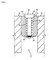
- Figure 1 is a view illustrating a venting apparatus(DE 195 43 276 C1) which is one of the conventional venting apparatuses.
- the venting apparatus includes a casing 14 inserted in a vent hole 12 of a mold 10, a valve body 18 inserted in a center through hole 16 of the casing 14, a spring(pressure or return spring) 20 elastically installed in the valve body 18, and a stopper 22 which is engaged to a lower end portion of the valve body 18 and controls a moving distance in a vertical direction of the valve body 18.
- valve body 18 includes a valve insert 24 which is provided in the center through hole 16 of the casing 14 and is surrounded by the spring 20, and a valve head 28 which contacts with a slant surface formed in an upper portion of the center through hole 16.
- the side surface of the valve head 28 has a slant surface 30 having the same slant angle as the slant angle of the slant surface 26 formed in the upper portion of the center through hole 16. Two slant surfaces 26 and 30 surface-contact each other, and the alternate interior angles of two slant surfaces are same.
- valve head 28 may be eccentric, so that the vent rubber may be formed in the vulcanized tire.
- the outer circumferential portion of the casing 14 is formed in a cylindrical shape and has the same diameter in its whole portions.
- the inner portion of the vent hole 12 of the mold 10 into which the casing 14 is inserted, is formed in a cylindrical shape.
- the inner diameter of the vent hole 12 is the same as the outer diameter of the casing 14, since the casing 14 is supported by only friction force with the inner circumferential portion of the vent hole 12, the casing 14 may be pushed into the interior of the vent hole 12 by a high pressure during the vulcanization.
- the inner volume of the center through hole 16 is always same in its upper and lower portion. Therefore, the space between the inner surfaces of the valve insert 24 and the center through hole 16 are very small, and the space in their upper and lower portions are same, in the case that the rubber which flows into the interior of the center through hole 16 is held between the spring 20, an elastic moving capacity of the valve body 18 may be lost, so that the venting apparatus may no be operated.
- DE 195 09 776 A1 a directly controlled pressure limiting valve is disclosed.
- DE 199 23 952 A1 discloses a venting apparatus for moulds.
- a moulding die for rubber product is disclosed in JP 56127439.
- European patent application EP 1 128 109 A1 discloses a valve for an actuating element, which can be used in control circuits in heating installations and air conditioning systems.
- US 2002/0079332 A1 discloses a valve apparatus that can reduce the problem of solid particle damage within the valve and which can also help reduce or avoid the problems associated with foreign objects becoming lodged within the valve.
- a steep-like throttling and reducing a valve is disclosed in WO 01/98694 A1.
- JP 60241586 discloses an electrically-driven control valve, which can be used in a refrigerating apparatus.
- these prior art references do not come closer to the invention than the above discussed prior art reference DE 195 43 276 C1.
- a venting apparatus for a tire vulcanizing mold which is capable of minimizing a length of a way of air which flows through a venting apparatus assuming that an introduction of rubber into a center through hole of a casing is not fully prevented, preventing a rubber from remaining in the interior of an air way, enhancing a vent performance when a space of a center through hole is largely formed and extending a life span of a venting apparatus.
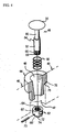
- Figure 2 is a disassembled perspective view illustrating a venting apparatus according to a first embodiment of the present invention
- Figure 3 is a vertical cross-sectional view illustrating the entire construction in a state that a venting apparatus of Figure 2 is engaged to a mold.
- the venting apparatus includes a casing 44 inserted in a vent hole 42 of a mold 40, a valve body 48 inserted tin a center through hole 46 of the casing 44, a spring 50 which surrounds a lower portion of the same for providing an elastic force to the valve body 48, and a stopper 52 which is engaged to a lower end portion of the valve body 48 and controls a moving vertical distance of the valve body 48.
- the inner diameter of the center through hole 46 formed in the casing 44 is gradually increased in the upper direction and is gradually decreased in the lower direction for thereby forming a taper shape.
- the valve body 48 is provided in the center through hole 46 of the casing 44 and is surrounded by the spring 50 for thereby providing a certain elastic force and includes a cylindrical valve insert 54 which has the same diameter, and a conical valve head 56 which is provided on an upper portion of the center through hole 46 and has a slant side surface formed in the top of the valve insert 54.
- an acute angle ⁇ 1 is preferably formed between the slant surface 60 and the upper surface of the valve head 56 contacting with an upper corner portion 58 of the center through hole 46
- an obtuse angle ⁇ 2 is preferably formed in the upper corner portion 58 of the center through hole 46 for the reason that in the case that the valve head 56 is lowered in the arrow direction of figure 3 due to an expansion of the green tire, the slant surface 60 of the valve head 56 is point-contacted with the upper corner portion 58 of the center through hole 46, not surface-contact each other, so that the green tire is prevented from being flown into the interior of the center through hole 46.
- a slant angle ⁇ 1 of the slant surface 60 of the valve head 56 is preferably set between 3° and 30°
- a slant angle ⁇ 2 of the upper corner portion 58 in the center through hole 46 is preferably set between 93° and 130°.
- the diameter of the valve insert 54 which is inserted in the spring 50 in the center through hole 46 of the casing 44 is same in its entire portions and is formed in a cylindrical shape.
- the stopper 52 installed in a lower end portion of the valve insert 54 is formed of the nut 62.
- the nut 62 is preferably formed of a cap nut which has a closed one side.
- the length of the portion in which a thread 64 is formed in the nut is the same as the entire moving length of the valve body 48. It is possible to uniformly adjust the moving lengths of the multiple valve bodies 48 which are in the mold 40 based on only an operation that the nut 64 is fully tightened to a bolt portion 66 formed at an end portion of the valve insert 54.
- penetrating holes 68 and 68' are formed in the center portion of the nut 62 and the front end portion of the bolt portion 66 engaged to the nut 62, respectively.
- a certain member capable of pressurizing a pat of an outer surface of the nut 62 may be used after the nut 62 is engaged to the bolt portion 66.
- the pressurizing degree is inwardly protruded by about 0.1 through 0.4mm compared to an outer diameter of the initial nut 62.
- a stopper pressurizing portion 72 is formed in order for a pressurizing tool to be inserted into a part of the outer surface of the nut 62 for implementing an easier pressurizing operation of the nut 62.
- an impact portion 74 is formed for applying a certain impact to a lower surface of the nut 62 for thereby minimizing a damage of the venting apparatus during a process that the venting apparatus is separated from the vent hole 42 for implementing an exchange and maintenance.
- an engaging shoulder 76 is outwardly protruded along an outer surface of the casing 44, and a mounting shoulder 78 is formed along an inner side surface of the vent hole 42 into which the casing 44 is inserted in order for the engaging shoulder 76 to be mounted. Therefore, it is possible to prevent the venting apparatus from being pushed into the interior of the vent hole 42 in the arrow direction by a high pressure during the tire vulcanization.
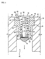
- Figure 4 is a disassembled perspective view illustrating a venting apparatus according to a second embodiment of the present invention
- Figure 5 is a vertical cross sectional view illustrating the entire construction in a state that a venting apparatus of Figure 4 is engaged to a mold.
- the constructions of Figures 4 and 5 are similar to the constructions of Figure 2 and 3. Therefore, the same reference numerals are given to the same elements.
- the valve insert 54 which us surrounded by the spring 50 in the center through hole 46 of the casing 44 is formed in such a manner that the diameter of the upper portion 80 near the valve head 56 is narrower, and the diameter of the lower portion 82 far from the valve head 56 is wider.
- the diameter D1 of the upper portion 80 is in a range of 5 through 70% compared to the diameter D2 of the lower portion 82, so that it is possible to obtain a certain space into which the rubber flows in.
- the length L1 of the upper portion 80 is preferably less than half of the entire length L2.
- venting apparatus As the green tire inserted in the vulcanization mold 40 is expanded by a bladder, and the air between the green tire and the mold 40 is discharged to the outside of the mold 40 through a gap between the valve head 56 and the center through hole 46.
- the surface of the green tire contacts with the valve head 56, and the valve body 48 presses the spring 50 and is lowered in the arrow direction of Figures 3 and 5.
- the center through hole 46 is disconnected at the time when the slant surface 60 of the valve head 56 contacts with the corner portion 58 of the upper end of the center through hole 46, so that the green tire does not flow into the interior of the center through hole 46.
Landscapes
- Engineering & Computer Science (AREA)
- Mechanical Engineering (AREA)
- Moulds For Moulding Plastics Or The Like (AREA)
- Heating, Cooling, Or Curing Plastics Or The Like In General (AREA)
Claims (9)
- Dispositif d'évacuation d'air pour un moule de vulcanisation, ledit dispositif comprenant :a) un carter (44) inséré dans un trou d'évacuation d'air (42) du moule,b) un corps de soupape (48) constitué d'une tête de soupape (56) insérée dans un trou débouchant central (46) du carter (44) et d'une tige de soupape (54),c) un ressort (50) entourant la tige de soupape (54) pour soumettre le corps de soupape (48) à une force élastique définie, etd) une pièce d'arrêt (52) engagée vers une partie d'extrémité inférieure de la tige de soupape (54) et déterminant couramment la course de déplacement totale du corps de soupape (48) dans une direction verticale,
caractérisé en ce quee) un diamètre intérieur du trou débouchant central (46) dans le carter (44) est progressivement agrandi vers le haut et progressivement diminué vers le bas pour réaliser ainsi une forme conique, etf) un angle d'obliquité (θ1) d'une surface oblique (60) de la tête de soupape (56) en contact ponctuel avec une partie de bord supérieure (58) du trou débouchant central (46) est différent d'un angle d'obliquité (θ2) de la partie de bord supérieure (58) du trou débouchant central (46). - Dispositif selon la revendication 1, où l'angle d'obliquité (θ1) de la surface oblique (60) de la tête de soupape (56) est un angle aigu, et où l'angle d'obliquité (θ2) de la partie de bord supérieure (58) du trou débouchant central (46) est un angle obtus.
- Dispositif selon la revendication 2, où l'angle d'obliquité (θ1) de la surface oblique (60) de la tête de soupape (56) est compris entre 3° et 30°, et où l'angle d'obliquité (θ2) de la partie de bord supérieure (58) du trou débouchant central (46) est compris entre 93° et 130°.
- Dispositif selon la revendication 1, où, sur la tige de soupape (54), un diamètre (D1) d'une partie supérieure (80) proche de la tête de soupape (56) est inférieur au diamètre (D2) d'une partie inférieure (82) éloignée de ladite tête, et où la longueur (L1) de la partie supérieure (80) est inférieure à la moitié de la longueur totale (L2) de la tige de soupape (54).
- Dispositif selon la revendication 1, où le carter (44) comprend un épaulement d'insertion (76) le long d'une de ses surfaces extérieures, et où un épaulement de montage (78) est formé le long d'une surface intérieure du trou d'évacuation d'air (42) dans lequel le carter (44) est inséré, pour permettre le montage de l'épaulement d'insertion (76).
- Dispositif selon la revendication 1, où la pièce d'arrêt (52) montée sur la partie d'extrémité inférieure de la tige de soupape (54) est un écrou (62) avec un côté borgne, et où la longueur d'un filet de l'écrou (62) est égale à la course de déplacement totale du corps de soupape (48) dans une direction verticale.
- Dispositif selon la revendication 6, où des trous débouchants (68, 68') sont ménagés respectivement sur une partie centrale de l'écrou (62) et sur une partie d'extrémité d'une partie de vissage (66) formée sur une partie d'extrémité de la tige de soupape (54), une goupille de fixation (70) étant insérée dans les trous débouchants (68, 68') pour empêcher le desserrage de l'écrou (62).
- Dispositif selon la revendication 6 ou la revendication 7, où une partie d'impact (74) est formée sur une surface inférieure de l'écrou (62) pour limiter un endommagement du dispositif d'évacuation d'air quand le dispositif d'évacuation d'air est dégagé du trou d'évacuation d'air.
- Dispositif selon la revendication 6 ou la revendication 7, où une partie de pressurisation (72) de la pièce d'arrêt est formée sur une partie d'une surface extérieure de l'écrou (62), de telle manière que l'écrou (62) présentant un rentrant intérieur de 0,1 à 0,4 mm environ par rapport à un diamètre extérieur minimal de l'écrou (62) pour permettre l'engagement d'un outil de pressurisation, ne soit pas desserré de la tige de soupape (54).
Applications Claiming Priority (4)
| Application Number | Priority Date | Filing Date | Title |
|---|---|---|---|
| KR2002038710 | 2002-07-04 | ||
| KR1020020038710A KR20040003883A (ko) | 2002-07-04 | 2002-07-04 | 가류금형용 벤트장치 |
| KR2002076003 | 2002-12-02 | ||
| KR10-2002-0076003A KR100498023B1 (ko) | 2002-12-02 | 2002-12-02 | 타이어 가류금형의 벤트장치 |
Publications (3)
| Publication Number | Publication Date |
|---|---|
| EP1380397A2 EP1380397A2 (fr) | 2004-01-14 |
| EP1380397A3 EP1380397A3 (fr) | 2005-05-18 |
| EP1380397B1 true EP1380397B1 (fr) | 2007-04-04 |
Family
ID=29738517
Family Applications (1)
| Application Number | Title | Priority Date | Filing Date |
|---|---|---|---|
| EP03003791A Expired - Lifetime EP1380397B1 (fr) | 2002-07-04 | 2003-02-19 | Dispositif d'évacuation d'air pour un moule de vulcanisation de pneumatiques |
Country Status (5)
| Country | Link |
|---|---|
| US (1) | US6923629B2 (fr) |
| EP (1) | EP1380397B1 (fr) |
| JP (1) | JP3717895B2 (fr) |
| CN (1) | CN1238171C (fr) |
| DE (1) | DE60312930T2 (fr) |
Cited By (2)
| Publication number | Priority date | Publication date | Assignee | Title |
|---|---|---|---|---|
| US8048247B2 (en) | 2004-12-28 | 2011-11-01 | Pirelli Tyre S.P.A. | Method and apparatus for manufacturing tyres for vehicle wheels |
| US8882947B2 (en) | 2004-12-28 | 2014-11-11 | Pirelli Tyre S.P.A. | Method and apparatus for manufacturing tyres for vehicle wheels |
Families Citing this family (28)
| Publication number | Priority date | Publication date | Assignee | Title |
|---|---|---|---|---|
| US7229264B2 (en) * | 2004-07-28 | 2007-06-12 | Wayne Crooks | Platen with self-cleaning exhaust holes and multi-opening press utilizing same |
| WO2006080378A1 (fr) * | 2005-01-28 | 2006-08-03 | Yugenkaisha T & K Corporation | Piece de conduit et matrice avec une piece de conduit attachee a celle-ci |
| SK92006A3 (sk) * | 2006-01-17 | 2007-08-02 | Matador, A.S. | Odvzdušňovací ventil do odvzdušňovacieho otvoru vulkanizačnej formy na výrobu pneumatík |
| KR101217986B1 (ko) * | 2006-01-24 | 2013-01-02 | 요코하마 고무 가부시키가이샤 | 타이어 성형용 금형, 타이어 성형용 금형의 벤트 홀에 사용하는 플러그 및 그 타이어 성형용 금형을 사용하여 제조한 타이어 |
| SK287193B6 (sk) | 2006-03-03 | 2010-03-08 | Glebus Alloys Europe S.R.O. | Odvzdušňovací ventil do odvzdušňovacích otvorov vulkanizačných foriem |
| US20070278707A1 (en) * | 2006-06-02 | 2007-12-06 | Koberlein Bernard M | Tire mold having air vents and vent plugs, and method for the manufacture thereof |
| US7530807B2 (en) * | 2007-01-30 | 2009-05-12 | Yu-Pei Ho | Mold structure with an ejecting tube for ejecting a molded product and permitting airflow |
| US7530803B2 (en) * | 2007-05-08 | 2009-05-12 | Bridgestone Firestone North American Tire, Llc | Insert for a tire mold vent |
| KR100855209B1 (ko) * | 2007-06-13 | 2008-09-01 | 한국타이어 주식회사 | 타이어 가류금형의 벤트장치 |
| KR100863214B1 (ko) * | 2007-06-26 | 2008-10-13 | 한국타이어 주식회사 | 타이어 가류금형의 벤트 장치 |
| FI119626B (fi) | 2007-07-11 | 2009-01-30 | Wd Racing Oy | Vulkanointimuotin ilmanpoistoventtiili |
| CN101821074B (zh) * | 2007-10-23 | 2014-03-19 | 倍耐力轮胎股份公司 | 用于硫化和模制轮胎的设备和方法 |
| KR101025716B1 (ko) * | 2008-01-28 | 2011-03-30 | 가부시키가이샤 사이토 가나가타 세이사쿠쇼 | 금형 내의 기체방출구조 및 당해 구조를 구비한 금형 |
| JP5291976B2 (ja) * | 2008-04-21 | 2013-09-18 | 東洋ゴム工業株式会社 | タイヤ加硫金型用ベントプラグ、タイヤ加硫金型、及び該タイヤ加硫金型を使用した空気入りタイヤの製造方法 |
| DE102009021697B4 (de) * | 2009-02-17 | 2015-04-02 | Ftm Formentechnik U. Metallbau Gmbh | Reinigung von Formen zur Herstellung von Reifenprofilen |
| CN102615762A (zh) * | 2012-04-19 | 2012-08-01 | 湖北航天化学技术研究所 | 橡胶模压制品模具 |
| JP6113564B2 (ja) * | 2013-04-17 | 2017-04-12 | 東洋ゴム工業株式会社 | タイヤ加硫金型及びそれに用いるタイヤ加硫金型用ベントプラグ |
| US9085114B2 (en) | 2013-12-13 | 2015-07-21 | Jens Guenter Gaebelein | Methods for manufacturing a tire mold and displacing the air from the mold into a compression cavity during the tire making process |
| EP3092113A4 (fr) * | 2014-01-09 | 2017-10-11 | Bridgestone Americas Tire Operations, LLC | Évent de moule de bandage |
| JP6514050B2 (ja) * | 2015-06-09 | 2019-05-15 | 株式会社ブリヂストン | ゴム物品用モールドの製造方法 |
| JP6706492B2 (ja) * | 2015-12-03 | 2020-06-10 | Toyo Tire株式会社 | タイヤ加硫金型及びタイヤの製造方法 |
| DE102016209910A1 (de) * | 2016-06-06 | 2017-12-07 | Continental Reifen Deutschland Gmbh | Entlüftungseinheit für eine Vulkanisationsform eines Fahrzeugluftreifens |
| FI129777B (en) * | 2017-04-12 | 2022-08-31 | Wd Racing Oy | VALVE INSERT AND BREATHER VALVE |
| US10814573B2 (en) | 2017-07-20 | 2020-10-27 | Bridgestone Americas Tire Operations, Llc | Bead ring design improvement |
| US20190047182A1 (en) | 2017-08-10 | 2019-02-14 | Avonisys Ag | Methods and systems for rubber removal from vulcanization molds |
| CN108748811B (zh) * | 2018-08-14 | 2023-11-17 | 高密同创气门芯有限公司 | 一种排气装置、其组装方法及具有该排气装置的轮胎模具 |
| FI128331B (en) | 2018-10-11 | 2020-03-31 | Wd Racing Oy | The vent valve |
| TWI790840B (zh) * | 2021-12-03 | 2023-01-21 | 陳銘棟 | 塑膠、橡膠、發泡模具之模內排氣治具結構 |
Family Cites Families (13)
| Publication number | Priority date | Publication date | Assignee | Title |
|---|---|---|---|---|
| CH547138A (de) * | 1972-10-05 | 1974-03-29 | Hodler Fritz | Entlueftungsventil zum schliessen des entlueftungskanals von giessformen. |
| JPS56127439A (en) * | 1980-03-11 | 1981-10-06 | Yokohama Rubber Co Ltd:The | Molding die for rubber product |
| US4492554A (en) * | 1980-08-26 | 1985-01-08 | Corn States Metal Fabricators, Inc. | Valve unit for a mold vent |
| JPS60241586A (ja) * | 1984-05-15 | 1985-11-30 | Saginomiya Seisakusho Inc | 冷凍装置における電動式コントロ−ルバルブ |
| DE19509776A1 (de) * | 1995-03-17 | 1996-09-19 | Rexroth Mannesmann Gmbh | Direktgesteuertes Druckbegrenzungsventil |
| DE19543276C1 (de) * | 1995-11-20 | 1997-02-06 | Continental Ag | Reifenvulkanisationsform mit Entlüftung |
| JP3772244B2 (ja) * | 1997-01-28 | 2006-05-10 | 株式会社ブリヂストン | 合成樹脂発泡成形品の成形金型及び成形方法 |
| GB9708584D0 (en) * | 1997-04-29 | 1997-06-18 | Sp Tyres Uk Ltd | Mould vents |
| US5997783A (en) * | 1997-10-31 | 1999-12-07 | Woodbridge Foam Corporation | Method for producing a molded article using a vented mold |
| GB2339163B (en) * | 1998-05-27 | 2002-12-24 | Dunlop Tyres Ltd | Mould vents |
| EP1128109A1 (fr) * | 2000-02-22 | 2001-08-29 | Siemens Building Technologies AG | Vanne pour dispositif de commande |
| WO2001098694A1 (fr) * | 2000-06-12 | 2001-12-27 | Jianran Ma | Soupape de retenue assurant une limitation du debit multiniveau dont la configuration est en gradins |
| US6701955B2 (en) * | 2000-12-21 | 2004-03-09 | Schlumberger Technology Corporation | Valve apparatus |
-
2003
- 2003-02-17 JP JP2003038160A patent/JP3717895B2/ja not_active Expired - Fee Related
- 2003-02-19 EP EP03003791A patent/EP1380397B1/fr not_active Expired - Lifetime
- 2003-02-19 DE DE60312930T patent/DE60312930T2/de not_active Expired - Lifetime
- 2003-02-26 US US10/374,862 patent/US6923629B2/en not_active Expired - Lifetime
- 2003-03-20 CN CNB031073484A patent/CN1238171C/zh not_active Expired - Fee Related
Cited By (4)
| Publication number | Priority date | Publication date | Assignee | Title |
|---|---|---|---|---|
| US8048247B2 (en) | 2004-12-28 | 2011-11-01 | Pirelli Tyre S.P.A. | Method and apparatus for manufacturing tyres for vehicle wheels |
| US8506274B2 (en) | 2004-12-28 | 2013-08-13 | Pirelli Tyre S.P.A. | Apparatus for manufacturing tyres for vehicle wheels |
| US8882947B2 (en) | 2004-12-28 | 2014-11-11 | Pirelli Tyre S.P.A. | Method and apparatus for manufacturing tyres for vehicle wheels |
| US9604421B2 (en) | 2004-12-28 | 2017-03-28 | Pirelli Tyre S.P.A. | Apparatus for manufacturing tyres for vehicle wheels |
Also Published As
| Publication number | Publication date |
|---|---|
| CN1467071A (zh) | 2004-01-14 |
| EP1380397A2 (fr) | 2004-01-14 |
| JP2004034691A (ja) | 2004-02-05 |
| US6923629B2 (en) | 2005-08-02 |
| US20040005371A1 (en) | 2004-01-08 |
| DE60312930D1 (de) | 2007-05-16 |
| EP1380397A3 (fr) | 2005-05-18 |
| JP3717895B2 (ja) | 2005-11-16 |
| DE60312930T2 (de) | 2007-12-13 |
| CN1238171C (zh) | 2006-01-25 |
Similar Documents
| Publication | Publication Date | Title |
|---|---|---|
| EP1380397B1 (fr) | Dispositif d'évacuation d'air pour un moule de vulcanisation de pneumatiques | |
| US11090842B2 (en) | Valve insert and air venting valve | |
| EP2173532B1 (fr) | Soupape et procede de purge d'air d'un moule de vulcanisation | |
| KR100956242B1 (ko) | 타이어 가류금형용 미니벤트 | |
| US9522509B2 (en) | Tire mold vent | |
| KR101612055B1 (ko) | 타이어 금형의 스프링을 구비한 벤트 장치 | |
| US10006554B2 (en) | Spring vent of tire vulcanizing mold | |
| KR100443645B1 (ko) | 벤트 플러그 및 그 벤트 플러그를 구비한 타이어 가류 몰드 | |
| KR100498023B1 (ko) | 타이어 가류금형의 벤트장치 | |
| KR100570869B1 (ko) | 타이어 가류금형의 벤트장치 | |
| KR100509188B1 (ko) | 타이어 가류금형의 벤트장치 | |
| US20230349476A1 (en) | Venting valve and method of mounting valve stem of venting valve | |
| KR20160148964A (ko) | 타이어 가황금형용 벤트 플러그 | |
| CN112839783B (zh) | 通风阀 | |
| KR101497635B1 (ko) | 타이어 가류 금형의 밴트장치 | |
| KR100910045B1 (ko) | 벤트식출방지를 위한 타이어 몰드의 벤트장치 | |
| KR100792965B1 (ko) | 타이어 가류금형의 벤트장치 | |
| KR200376229Y1 (ko) | 타이어 가류금형의 벤트장치 | |
| KR101691330B1 (ko) | 타이어 금형의 에어배출장치 |
Legal Events
| Date | Code | Title | Description |
|---|---|---|---|
| PUAI | Public reference made under article 153(3) epc to a published international application that has entered the european phase |
Free format text: ORIGINAL CODE: 0009012 |
|
| AK | Designated contracting states |
Kind code of ref document: A2 Designated state(s): AT BE BG CH CY CZ DE DK EE ES FI FR GB GR HU IE IT LI LU MC NL PT SE SI SK TR |
|
| AX | Request for extension of the european patent |
Extension state: AL LT LV MK RO |
|
| PUAL | Search report despatched |
Free format text: ORIGINAL CODE: 0009013 |
|
| AK | Designated contracting states |
Kind code of ref document: A3 Designated state(s): AT BE BG CH CY CZ DE DK EE ES FI FR GB GR HU IE IT LI LU MC NL PT SE SI SK TR |
|
| AX | Request for extension of the european patent |
Extension state: AL LT LV MK RO |
|
| RIC1 | Information provided on ipc code assigned before grant |
Ipc: 7B 29D 30/26 B Ipc: 7B 29D 30/06 B Ipc: 7B 29L 30:00 Z Ipc: 7B 29C 33/10 A Ipc: 7F 16K 24/04 B |
|
| 17P | Request for examination filed |
Effective date: 20051028 |
|
| AKX | Designation fees paid |
Designated state(s): DE FR GB IT |
|
| GRAP | Despatch of communication of intention to grant a patent |
Free format text: ORIGINAL CODE: EPIDOSNIGR1 |
|
| RIC1 | Information provided on ipc code assigned before grant |
Ipc: B29C 33/10 20060101AFI20060921BHEP Ipc: B29D 30/26 20060101ALI20060921BHEP Ipc: B29D 30/06 20060101ALI20060921BHEP Ipc: F16K 24/04 20060101ALI20060921BHEP |
|
| GRAS | Grant fee paid |
Free format text: ORIGINAL CODE: EPIDOSNIGR3 |
|
| GRAA | (expected) grant |
Free format text: ORIGINAL CODE: 0009210 |
|
| AK | Designated contracting states |
Kind code of ref document: B1 Designated state(s): DE FR GB IT |
|
| REG | Reference to a national code |
Ref country code: GB Ref legal event code: FG4D |
|
| REF | Corresponds to: |
Ref document number: 60312930 Country of ref document: DE Date of ref document: 20070516 Kind code of ref document: P |
|
| ET | Fr: translation filed | ||
| PLBE | No opposition filed within time limit |
Free format text: ORIGINAL CODE: 0009261 |
|
| STAA | Information on the status of an ep patent application or granted ep patent |
Free format text: STATUS: NO OPPOSITION FILED WITHIN TIME LIMIT |
|
| 26N | No opposition filed |
Effective date: 20080107 |
|
| REG | Reference to a national code |
Ref country code: FR Ref legal event code: PLFP Year of fee payment: 14 |
|
| REG | Reference to a national code |
Ref country code: FR Ref legal event code: PLFP Year of fee payment: 15 |
|
| PGFP | Annual fee paid to national office [announced via postgrant information from national office to epo] |
Ref country code: FR Payment date: 20170106 Year of fee payment: 15 Ref country code: DE Payment date: 20170104 Year of fee payment: 15 |
|
| PGFP | Annual fee paid to national office [announced via postgrant information from national office to epo] |
Ref country code: GB Payment date: 20170105 Year of fee payment: 15 |
|
| PGFP | Annual fee paid to national office [announced via postgrant information from national office to epo] |
Ref country code: IT Payment date: 20170217 Year of fee payment: 15 |
|
| REG | Reference to a national code |
Ref country code: DE Ref legal event code: R119 Ref document number: 60312930 Country of ref document: DE |
|
| GBPC | Gb: european patent ceased through non-payment of renewal fee |
Effective date: 20180219 |
|
| REG | Reference to a national code |
Ref country code: FR Ref legal event code: ST Effective date: 20181031 |
|
| PG25 | Lapsed in a contracting state [announced via postgrant information from national office to epo] |
Ref country code: DE Free format text: LAPSE BECAUSE OF NON-PAYMENT OF DUE FEES Effective date: 20180901 |
|
| PG25 | Lapsed in a contracting state [announced via postgrant information from national office to epo] |
Ref country code: FR Free format text: LAPSE BECAUSE OF NON-PAYMENT OF DUE FEES Effective date: 20180228 Ref country code: GB Free format text: LAPSE BECAUSE OF NON-PAYMENT OF DUE FEES Effective date: 20180219 Ref country code: IT Free format text: LAPSE BECAUSE OF NON-PAYMENT OF DUE FEES Effective date: 20180219 |