EP1378807A2 - Procédé pour mesurer la température d'un récipient de cuisson métallique - Google Patents
Procédé pour mesurer la température d'un récipient de cuisson métallique Download PDFInfo
- Publication number
- EP1378807A2 EP1378807A2 EP03014933A EP03014933A EP1378807A2 EP 1378807 A2 EP1378807 A2 EP 1378807A2 EP 03014933 A EP03014933 A EP 03014933A EP 03014933 A EP03014933 A EP 03014933A EP 1378807 A2 EP1378807 A2 EP 1378807A2
- Authority
- EP
- European Patent Office
- Prior art keywords
- temperature
- cooking vessel
- resonant circuit
- induction coil
- heater
- Prior art date
- Legal status (The legal status is an assumption and is not a legal conclusion. Google has not performed a legal analysis and makes no representation as to the accuracy of the status listed.)
- Granted
Links
Images

Classifications
-
- G—PHYSICS
- G05—CONTROLLING; REGULATING
- G05D—SYSTEMS FOR CONTROLLING OR REGULATING NON-ELECTRIC VARIABLES
- G05D23/00—Control of temperature
- G05D23/19—Control of temperature characterised by the use of electric means
- G05D23/20—Control of temperature characterised by the use of electric means with sensing elements having variation of electric or magnetic properties with change of temperature
-
- G—PHYSICS
- G05—CONTROLLING; REGULATING
- G05D—SYSTEMS FOR CONTROLLING OR REGULATING NON-ELECTRIC VARIABLES
- G05D23/00—Control of temperature
- G05D23/19—Control of temperature characterised by the use of electric means
- G05D23/1917—Control of temperature characterised by the use of electric means using digital means
Definitions
- the invention relates to a method for measuring the temperature of a metallic cooking vessel in the area of a heater according to the preamble of claim 1 and an electric heating device with temperature measurement according to the preamble of claim 15.
- Processes and heaters provided with suitable facilities for measuring the temperature of a metal saucepan are known in many forms.
- a temperature control from it For example, an attempt has been made to make a resonant circuit an induction coil together with the metal saucepan base to build. This allows, for example, the resonant circuit frequency of the The bottom of the saucepan. This in turn is dependent on the temperature Permeability of the material of the saucepan base determined.
- this requires that Calibrate the system at great expense to provide reasonably accurate temperature information to be able to do. This is considered to be disadvantageous.
- the invention has for its object an aforementioned method and to create a heater with which the disadvantages of State of the art can be avoided, in particular on a complex and error-prone adjustment of inductive temperature detection systems can be dispensed with.
- the method provides that an inductive Sensor and evaluation electronics for recording and controlling the Temperature of the cooking vessel are provided.
- the inductive Sensor and the metallic cooking vessel part of a resonant circuit, whereby a resonant circuit parameter is measured.
- a resonant circuit parameter can, for example, the frequency or a phase angle or an attenuation or a conductance can be determined.
- the temporal The course of the resonant circuit parameter is recorded.
- a resonant circuit parameter can, for example, the frequency or a phase angle or an attenuation or a conductance can be determined.
- the temporal The course of the resonant circuit parameter is recorded.
- a special feature of the invention that in certain sections a normal cooking process, especially the beginning of boiling of water or liquid in the cooking vessel, the temperature of the Cooking vessel or the bottom of the cooking vessel no significant change learns more.
- Boiling water can be in a normal cooking vessel do not assume a temperature higher than 100 ° C. That point at which the temperature of the cooking vessel and thus also the measured Oscillating circuit parameters such as frequency are no longer essential changes, is recorded as a characteristic section. In particular the gradient of the course changes greatly here. For this characteristic In turn, the temperature is determined, for example when water begins to boil as temperature of approximately 100 ° C.
- the heater has, as is often the case, a metallic or even ferromagnetic carrier. This also heats up in heating mode, which also seeks its permeability and thus its resonant circuit behavior to change. Since it is part of the inductive resonant circuit, the wearer also creates a changing, disruptive influence for the resonant circuit and thus the resonant circuit parameters or temperature detection. According to the temperature of the carrier measured and processed to a correction value. With this correction value the measured resonant circuit parameter is then corrected in such a way that the disturbing influence of the wearer is eliminated.
- a change in the slope of the measured value curve is advantageous Decrease in slope used. This can be the transition to one be a substantially constant measured value, which is approximately one constant temperature of the cooking vessel corresponds.
- the correction values can be saved. This can be related with the temperature of the carrier, the time or the energy coupling respectively.
- the correction values can be saved in the form of curves or the corresponding values.
- the correction values can so to speak as a family of curves with certain parameters get saved. This can depend on, for example certain energy coupling over a certain time.
- the temperature can be measured using a resistance sensor. This can also depend on certain use cases. A temperature measurement and determination of the correction value takes place preferably repeated, in particular continuously.
- a controller can be provided for a correction value.
- a coil is advantageously used as an inductive sensor.
- This can in one embodiment of the invention, a pot detection coil his.
- the coil advantageously has a few turns. Particularly advantageous the coil has only a single turn, whereby the Reduce the effort required to manufacture and hold such a coil leaves.
- a straight inductive sensor a so-called linear sensor, is used become.
- induction heating with a To use induction coil This is where the induction coil becomes advantageous used as a sensor for temperature measurement. This is preferably done in a kind of clocked or alternating operation with the heating function the induction coil. So it is time-wise in sections the induction coil on the one hand heats the cooking vessel and on the other hand the resonant circuit parameter is recorded or the temperature measured.
- the induction coil can advantageously make electrical contact have in their course on a turn or the like.
- the contacting should be geometrically in an area of the induction coil, in which the temperature measurement of the cooking vessel should take place or this is arranged.
- electrical contacting the induction coil is divided into at least two areas. A part or area of the induction coil is used for temperature measurement used.
- the entire induction coil does not need to be controlled and operated as an inductive sensor, what is advantageous.
- induction coils are advantageously spiral-shaped.
- An electrical heating device with a temperature measurement has a heater, an inductive sensor and evaluation electronics to regulate the temperature. Particularly preferred it is a hob of a hob with which a cooking vessel placed on it can be heated.
- the inductive Sensor and a metallic to be heated with the heating device Cooking vessels are part of an oscillating circuit. So by means of Sensor whose resonant circuit parameters or, for example, the frequency of the cooking vessel.
- the evaluation electronics is Acquisition of the resonant circuit parameter as a measured value over its time Course formed as well as from a characteristic section the course of the curve as described above, determine the temperature of the cooking vessel.
- the induction coil forms the sensor.
- the Induction coil it is advantageously possible at the Induction coil to provide an electrical contact through which the induction coil in at least a first part and a second Part is shared.
- a divider of the induction coil can be used for temperature measurement be trained.
- the induction coil is spiral. It can an inner part of the coil is separated with an electrical contact and be designed for temperature measurement. For this he is with of the evaluation electronics connectable or connected for control. On other part of the induction coil, so the rest of the induction coil can be short-circuited.
- a glass ceramic cooktop 11 shown. Below a hotplate of the glass ceramic cooktop 11 is a radiant heater 13. This is in Principle trained in a known manner.
- a metal bowl 15, also called plate is a flat, also plate or bowl-shaped Insulating body 17 inserted.
- a heating coil 19 is embedded in the insulating body 17.
- the radiant heater 13 is from pressed down on the underside of the glass ceramic hob 11. This can be done for example by holding means, not shown.
- An induction coil 20 is arranged directly above the heating coil 19. As has been described, this can be carried out in different ways be, for example, single wind.
- the radiant heater 13 Above the radiant heater 13 is a saucepan 21 on the glass ceramic hob 11 put on.
- Energy is coupled into a saucepan base 22, which is ferromagnetic for this purpose is trained.
- Heat water 23 is brought to a boil. With this device or a method likewise described below is to be recognized be when the water 23 to boil inside the saucepan 21 starts.
- the radiant heater 13 or the heating coil 19 is with a controller 25 connected.
- the controller 25 has a microprocessor 26 on.
- Control 28 and display 29 can be in the usual way and be trained.
- controller 25 has a memory 31 which is connected to the Microprocessor 26 is connected.
- the controller 25 or the microprocessor are also in the exemplary representation for the energy supply responsible for heating coil 25.
- circuit breakers or the like may be included.
- the temperature of the metal shell 15 is measured directly. There is a Temperature sensor 16 attached to the underside of the metal shell 15. The location for attaching the temperature sensor should vary however, be chosen so that it is as representative as possible Place is appropriate.
- the temperature sensor 16 can be, for example Resistance sensor. He is with the controller 25 or the microprocessor 26 connected to the temperature of the metal shell at the Evaluation of the curves available.
- the induction coil is used to measure the temperature of the saucepan 21 20 by the controller 25 in addition to the inductive heating mode as an inductive one Sensor controlled.
- the controller 25 in addition to the inductive heating mode as an inductive one Sensor controlled.
- an induction coil an induction heater. This could then alternately controlled as a heater and as an inductive sensor become.
- Such an alternate activation of the induction coil both as an inductive heating as well as an inductive sensor is for the Expert known per se.
- the induction coil 20 forms part of an inductive oscillating circuit, in which the saucepan base 22 and the metal shell 15 are integrated are.
- the metal bowl 15 and the saucepan base 22 have a temperature-dependent permeability and thus inductance on which influences the inductive oscillating circuit and via the induction coil 20 can be recorded.
- the method according to the invention is based, inter alia, on thereon, that due to the change in inductance the bottom of the saucepan 22 inferred from the temperature depending on the temperature can be.
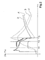
- Fig. 2 are different curves for the frequency f and the temperature T is plotted over time t. Times don't play in themselves Role. To illustrate, it can be said that the curves in about up to a time of 60 minutes. However, this is only exemplary and serves for clarity. The frequencies are also variable. The frequencies shown here are in the range of just over 3.3Mhz. This information also serves only for clarity and can vary widely.
- the temperature profiles have a kind Saddle point at 100 ° C, more on that later.
- a dashed curve A is shown on the one hand. This is not a dashed curve compensated curve of the frequency of the entire resonant circuit the time, which consists of induction coil 20, saucepan base 22 and metal bowl 15 exists. In addition, there is also the heating coil 19.
- the dotted curve B represents the course of the temperature T above the Time t is only for pot 21. Here is an influence of the metal shell 15 not taken into account. This curve is like having a separate one Temperature measuring device would have been determined.
- the dash-dotted curve C represents the course the temperature T over time t isolated for the metal shell.
- the flat and the temperature rise of the metal shell 15, which is greatly delayed stems from the fact that the heat through the insulating body 17 is only relatively slow migrates into the metal shell 15.
- Curve D represents a compensated version of curve A according to Adjustment from the influence that the metal shell 15 exerts. Based the frequency curve D can detect the temperature of the cooking vessel 21 take place.
- a time T1 is also shown. This marks in time Course the beginning of the boiling of water 23. This beginning of boiling namely means that the temperature of the saucepan 21 or the pot bottom 22 no longer changes, but approximately constant Is 100 ° C.
- the next point in time T2 indicates over time the point where, either by normal heating or by boiling the water 23 is completely evaporated in the saucepan 21. From this point on again an increase in temperature and thus a further change in Frequency f take place.
- the heater 13 was switched off. The temperatures then drop.
- the point at T1 can be used as a control point for temperature control 100 ° C can be used.
- Curve B shows how the temperature of the saucepan changes 21 does not change between T1 and T2. Only by boiling the Pot from T2 onwards, the temperature increases again.
- the curve C of the metal shell 15, shows the influence of Of course, not cooking the pot 21.
- T1 and T2 the temperature the metal shell is slowly but steadily increasing, and only then a good bit after T2 reaches its maximum value.
- This continuous Rise in temperature of the metal shell 15 mainly between The times T1 and T2 is the reason why without compensation this influence the curve A has the shape shown and for a accurate temperature evaluation is not suitable or causes errors.
- Curve B represents the curve used for evaluating the temperature would be ideal. However, since it cannot be avoided that the metal shell 15 is in the inductive resonant circuit and thus has an influence on the exercises measured curve A, the influence of the metal shell 15 must be taken into account with the temperature according to curve C.
- the curve A is detected by the inductive sensor 19.
- the known curve C for example, once in a reference measurement process captured for a particular metal shell 15 and then can be stored in the memory 31 is used as a correction value used and offset against curve A in a certain way.
- the result of this calculation is the curve D.
- Aus This curve D shows the changes in the courses the times T1 and T2 are relatively easy to grasp and can be from one Control can be evaluated accordingly.
- the curves can C must be stored.
- the controller 25 can at any time determine at which point of curve C you are currently.
- the frequency and temperature of the metal shell 15 connected via the physical conditions.
- the Controller from curve C the necessary correction values at any time remove to correct curve A.
- the controller 25 just receives the curve D.
- time T1 as well as Time T2 can be determined exactly.
- the curves C are advantageously already stored in the memory 31 at the factory stored. So this process does not need for every inductive one Heater 13 to be made separately. Also relationships with an energy input via the heater can be saved be used to measure the temperature of the metal shell and to be able to save the associated effort.
- the invention is also based on the fact that the distance between the metal shell 15 and the heating coil 19 structurally predetermined and thus is always the same. Therefore, it can be based on the measured Temperature of the metal shell recorded influence of the metal shell on the Record, determine and store the measured frequency of curve A. This influence can just as easily be corrected afterwards can be calculated from curve A, whereby curve B receives.
- Assign initial temperature for example room temperature
- a temperature lower than 100 ° C for example 70 ° C or 80 ° C
- the controller 25 can do the energy coupling Control over the heating coil 19 so that approximately this frequency and thus the desired temperature is maintained.
- the starting temperature for such a process can be, for example can be entered via control element 28 or the like.
- alternative can be assumed that when putting on a Cooking pot 21 and its contents always have approximately room temperature.
Applications Claiming Priority (2)
| Application Number | Priority Date | Filing Date | Title |
|---|---|---|---|
| DE10231122A DE10231122A1 (de) | 2002-07-05 | 2002-07-05 | Verfahren zum Messen der Temperatur eines metallischen Kochgefäßes |
| DE10231122 | 2002-07-05 |
Publications (3)
| Publication Number | Publication Date |
|---|---|
| EP1378807A2 true EP1378807A2 (fr) | 2004-01-07 |
| EP1378807A3 EP1378807A3 (fr) | 2004-11-03 |
| EP1378807B1 EP1378807B1 (fr) | 2007-02-28 |
Family
ID=29719513
Family Applications (1)
| Application Number | Title | Priority Date | Filing Date |
|---|---|---|---|
| EP03014933A Expired - Lifetime EP1378807B1 (fr) | 2002-07-05 | 2003-07-01 | Procédé pour mesurer la température d'un récipient de cuisson métallique |
Country Status (6)
| Country | Link |
|---|---|
| US (1) | US6904378B2 (fr) |
| EP (1) | EP1378807B1 (fr) |
| CN (1) | CN100402998C (fr) |
| AT (1) | ATE355550T1 (fr) |
| DE (2) | DE10231122A1 (fr) |
| ES (1) | ES2281584T3 (fr) |
Cited By (2)
| Publication number | Priority date | Publication date | Assignee | Title |
|---|---|---|---|---|
| EP2312909A1 (fr) | 2009-10-19 | 2011-04-20 | Whirlpool Corporation | Procédé de contrôle de l'alimentation électrique pour le contenu liquide d'un appareil de cuisson |
| WO2012092683A3 (fr) * | 2011-01-07 | 2012-11-15 | Inducs Ag | Appareil de cuisson à induction destiné à une cuisson par commande de température |
Families Citing this family (45)
| Publication number | Priority date | Publication date | Assignee | Title |
|---|---|---|---|---|
| DE102004033115A1 (de) * | 2004-07-08 | 2006-02-09 | Albert Thomann | Verfahren und Vorrichtung zur thermostatischen Kochgeschirrregelung |
| ITMO20040193A1 (it) * | 2004-07-23 | 2004-10-23 | Angelo Grandi Cucine Spa | Sistema e sonda per la rivealzione di un parametro |
| ES2265758B1 (es) * | 2005-03-01 | 2007-11-16 | Bsh Electrodomesticos España, S.A. | Dispositivo de calentamiento para una cocina de induccion. |
| CN100458631C (zh) * | 2005-03-25 | 2009-02-04 | 深圳斯贝克动力电子有限公司 | 发热元件的温度控制方法和装置 |
| EP1729101B1 (fr) * | 2005-06-03 | 2008-09-10 | Fondazione Torino Wireless | Méthode et appareil pour la détection du niveau d'un métal en fusion dans un récipient et de l'épaisseur d'une couche de laitier flottant dessus |
| JP4793002B2 (ja) * | 2006-02-07 | 2011-10-12 | パナソニック株式会社 | 誘導加熱装置 |
| DE102006057885A1 (de) * | 2006-12-01 | 2008-06-05 | E.G.O. Elektro-Gerätebau GmbH | Verfahren zum Erzeugen, Verarbeiten und Auswerten eines mit der Temperatur korrelierten Signals und entsprechende Vorrichtung |
| ES2328546B1 (es) * | 2007-04-27 | 2010-08-30 | Bsh Electrodomesticos España, S.A. | Dispositivo de unidad de coccion. |
| US20080281318A1 (en) * | 2007-05-09 | 2008-11-13 | Tessaron Medical, Inc. | Systems and methods for inductive heat treatment of body tissue |
| DE102008006017B4 (de) * | 2008-01-25 | 2010-08-12 | Beurer Gmbh | Schmiegsames Wärmegerät |
| TWI394547B (zh) * | 2009-03-18 | 2013-05-01 | Delta Electronics Inc | 加熱裝置 |
| ES2378938B1 (es) | 2009-11-03 | 2013-03-14 | BSH Electrodomésticos España S.A. | Campo de cocción con al menos un sensor de temperatura. |
| CN102056356B (zh) * | 2009-11-09 | 2012-12-26 | 台达电子工业股份有限公司 | 智能加热装置与温度测量装置 |
| DE102009047185B4 (de) * | 2009-11-26 | 2012-10-31 | E.G.O. Elektro-Gerätebau GmbH | Verfahren und Induktionsheizeinrichtung zum Ermitteln einer Temperatur eines mittels einer Induktionsheizspule erwärmten Kochgefäßbodens |
| US8754351B2 (en) | 2010-11-30 | 2014-06-17 | Bose Corporation | Induction cooking |
| US9585202B2 (en) | 2011-05-20 | 2017-02-28 | Cooktek Induction Systems, Llc | Induction-based food holding/warming system and method |
| US9417292B1 (en) | 2011-06-08 | 2016-08-16 | Hrl Laboratories, Llc | Thermomagnetic temperature sensing |
| DE102011079689B4 (de) | 2011-07-22 | 2014-07-03 | E.G.O. Elektro-Gerätebau GmbH | Temperaturmessung im Kochgefäß |
| BR112013032558B1 (pt) | 2011-09-06 | 2021-01-12 | British American Tobacco (Investments) Limited | aparelho para aquecer material fumável |
| DE102011083386A1 (de) * | 2011-09-26 | 2013-03-28 | E.G.O. Elektro-Gerätebau GmbH | Verfahren zum Beheizen eines Kochgefäßes mittels einer Induktionsheizeinrichtung und Induktionsheizeinrichtung |
| DE102011083383A1 (de) * | 2011-09-26 | 2013-03-28 | E.G.O. Elektro-Gerätebau GmbH | Verfahren zum Beheizen einer in einem Kochgefäß enthaltenen Flüssigkeit und Induktionsheizeinrichtung |
| DE102011083397A1 (de) * | 2011-09-26 | 2013-03-28 | E.G.O. Elektro-Gerätebau GmbH | Verfahren zum Zubereiten von Lebensmitteln mittels einer Induktionsheizeinrichtung und Induktionsheizeinrichtung |
| KR20130073477A (ko) * | 2011-12-23 | 2013-07-03 | 삼성전자주식회사 | 유도가열조리기 및 그 제어방법 |
| US9618396B1 (en) | 2013-03-15 | 2017-04-11 | Hrl Laboratories, Llc | Thermomagnetic resonator-based temperature sensing |
| US9719863B1 (en) | 2013-03-15 | 2017-08-01 | Hrl Laboratories, Llc | Thermomagnetic temperature sensing |
| US9470423B2 (en) | 2013-12-02 | 2016-10-18 | Bose Corporation | Cooktop power control system |
| WO2015095885A1 (fr) * | 2013-12-20 | 2015-06-25 | Peterson Theresa | Dispositif vertical de cuisson de tortilla |
| EP3098508B1 (fr) * | 2013-12-27 | 2022-03-30 | Kawasaki Jukogyo Kabushiki Kaisha | Système d'estimation de la durée de vie d'un tube de transfert de chaleur |
| US11924930B2 (en) | 2015-08-31 | 2024-03-05 | Nicoventures Trading Limited | Article for use with apparatus for heating smokable material |
| US20170055584A1 (en) | 2015-08-31 | 2017-03-02 | British American Tobacco (Investments) Limited | Article for use with apparatus for heating smokable material |
| GB201518809D0 (en) * | 2015-10-23 | 2015-12-09 | The Technology Partnership Plc | Temperature sensor |
| DE102016205005A1 (de) * | 2016-03-24 | 2017-09-28 | BSH Hausgeräte GmbH | Kochvorrichtung mit Kalibrierfunktion |
| CN107436198B (zh) * | 2016-05-27 | 2021-03-30 | 浙江绍兴苏泊尔生活电器有限公司 | 锅具温度检测系统、方法和电磁炉 |
| CN107581888B (zh) * | 2016-07-07 | 2020-08-04 | 佛山市顺德区美的电热电器制造有限公司 | 电烹饪器的烹饪温度控制方法、装置及电烹饪器 |
| US10356853B2 (en) | 2016-08-29 | 2019-07-16 | Cooktek Induction Systems, Llc | Infrared temperature sensing in induction cooking systems |
| EP3300453B1 (fr) * | 2016-09-23 | 2020-08-19 | Electrolux Appliances Aktiebolag | Procédé de détection d'ébullition et table de cuisson à induction comprenant un mécanisme de détection d'ébullition |
| GB201705206D0 (en) | 2017-03-31 | 2017-05-17 | British American Tobacco Investments Ltd | Apparatus for a resonance circuit |
| GB201705208D0 (en) * | 2017-03-31 | 2017-05-17 | British American Tobacco Investments Ltd | Temperature determination |
| CN111385922B (zh) * | 2018-12-29 | 2022-04-01 | 佛山市顺德区美的电热电器制造有限公司 | 电磁加热器具的控制方法、装置及电磁加热器具 |
| CN111380627A (zh) * | 2018-12-29 | 2020-07-07 | 佛山市顺德区美的电热电器制造有限公司 | 电磁加热器具及其温度检测方法和装置 |
| CN112714516B (zh) * | 2019-10-25 | 2023-04-21 | 佛山市顺德区美的电热电器制造有限公司 | 电磁加热设备及其测温系统和测温方法 |
| CN112710412B (zh) * | 2019-10-25 | 2023-11-03 | 佛山市顺德区美的电热电器制造有限公司 | 电磁加热设备及其锅具标定方法和装置 |
| CN113660746B (zh) * | 2020-05-12 | 2022-11-01 | 佛山市顺德区美的电热电器制造有限公司 | 加热电路以及烹饪装置 |
| CN113741227B (zh) * | 2020-05-29 | 2023-08-29 | 佛山市顺德区美的电热电器制造有限公司 | 烹饪设备的控制方法、控制装置、烹饪设备和存储介质 |
| CN113729472A (zh) * | 2020-05-29 | 2021-12-03 | 佛山市顺德区美的电热电器制造有限公司 | 烹饪器具的控制方法、烹饪器具和计算机可读存储介质 |
Citations (4)
| Publication number | Priority date | Publication date | Assignee | Title |
|---|---|---|---|---|
| EP0658067A1 (fr) * | 1993-12-06 | 1995-06-14 | Bosch-Siemens HausgerÀ¤te GmbH | Commande pour l'évaluation des signaux des capteurs d'un appareil électro-ménager |
| DE4413979A1 (de) * | 1994-04-21 | 1995-10-26 | Bosch Siemens Hausgeraete | Sensorgesteuerte Garungseinheit |
| DE19540408A1 (de) * | 1995-10-30 | 1997-05-07 | Herchenbach Wolfgang | Kochsystem |
| US20020011480A1 (en) * | 2000-07-22 | 2002-01-31 | Wilfried Schilling | Temperature detection device for an electric radiant heater |
Family Cites Families (13)
| Publication number | Priority date | Publication date | Assignee | Title |
|---|---|---|---|---|
| US3887781A (en) * | 1971-04-06 | 1975-06-03 | Environment One Corp | Metal base cookware induction heating apparatus having improved control circuit using infra-red temperature sensor |
| US3973105A (en) * | 1973-10-24 | 1976-08-03 | Mitsubishi Denki Kabushiki Kaisha | Protective device for induction heating apparatus |
| US4013859A (en) * | 1975-06-04 | 1977-03-22 | Environment/One Corporation | Induction cooking unit having cooking load sensing device and essentially zero stand-by power loss |
| IE903986A1 (en) * | 1990-04-24 | 1991-11-06 | Lancet Sa | Cooking device |
| US5450305A (en) * | 1991-08-12 | 1995-09-12 | Auckland Uniservices Limited | Resonant power supplies |
| US5255975A (en) * | 1991-11-26 | 1993-10-26 | Honeywell Inc. | Low cost calibration system for frequency varying temperature sensing means for a thermostat |
| IT1260456B (it) * | 1992-01-28 | 1996-04-09 | Whirlpool Italia | Metodo e dispositivo per rilevare a presenza di un corpo per esempio una pentola su un piano di cottura in vetroceramica in corrispondenza di un elemento riscaldante associato a tale piano |
| KR0165303B1 (ko) * | 1994-11-30 | 1999-01-15 | 김광호 | 냉장고 마이크로프로세서의 온도 제어방법 |
| DE19526091A1 (de) * | 1995-07-18 | 1997-01-23 | Ego Elektro Blanc & Fischer | Einrichtung zur Temperaturbegrenzung eines elektrischen Wärmegerätes |
| DE19603845B4 (de) * | 1996-02-05 | 2010-07-22 | E.G.O. Elektro-Gerätebau GmbH | Elektrischer Strahlungsheizkörper mit einem aktiven Sensor zur Kochgefäßerkennung |
| DE19646826C5 (de) * | 1996-02-22 | 2008-10-16 | AEG Hausgeräte GmbH | Vorrichtung zur Temperaturmessung an Kochstellen |
| DE19729661A1 (de) * | 1997-07-11 | 1999-01-14 | Ego Elektro Geraetebau Gmbh | Erwärmungssystem |
| JP2001124633A (ja) * | 1999-10-26 | 2001-05-11 | Auto Denshi Kk | 測定データ検出装置 |
-
2002
- 2002-07-05 DE DE10231122A patent/DE10231122A1/de not_active Withdrawn
-
2003
- 2003-07-01 AT AT03014933T patent/ATE355550T1/de not_active IP Right Cessation
- 2003-07-01 DE DE50306630T patent/DE50306630D1/de not_active Expired - Lifetime
- 2003-07-01 ES ES03014933T patent/ES2281584T3/es not_active Expired - Lifetime
- 2003-07-01 EP EP03014933A patent/EP1378807B1/fr not_active Expired - Lifetime
- 2003-07-03 US US10/613,404 patent/US6904378B2/en not_active Expired - Fee Related
- 2003-07-05 CN CNB031546994A patent/CN100402998C/zh not_active Expired - Fee Related
Patent Citations (4)
| Publication number | Priority date | Publication date | Assignee | Title |
|---|---|---|---|---|
| EP0658067A1 (fr) * | 1993-12-06 | 1995-06-14 | Bosch-Siemens HausgerÀ¤te GmbH | Commande pour l'évaluation des signaux des capteurs d'un appareil électro-ménager |
| DE4413979A1 (de) * | 1994-04-21 | 1995-10-26 | Bosch Siemens Hausgeraete | Sensorgesteuerte Garungseinheit |
| DE19540408A1 (de) * | 1995-10-30 | 1997-05-07 | Herchenbach Wolfgang | Kochsystem |
| US20020011480A1 (en) * | 2000-07-22 | 2002-01-31 | Wilfried Schilling | Temperature detection device for an electric radiant heater |
Cited By (4)
| Publication number | Priority date | Publication date | Assignee | Title |
|---|---|---|---|---|
| EP2312909A1 (fr) | 2009-10-19 | 2011-04-20 | Whirlpool Corporation | Procédé de contrôle de l'alimentation électrique pour le contenu liquide d'un appareil de cuisson |
| US8598494B2 (en) | 2009-10-19 | 2013-12-03 | Whirlpool Corporation | Method for controlling power supply to the liquid contents of a cooking vessel |
| WO2012092683A3 (fr) * | 2011-01-07 | 2012-11-15 | Inducs Ag | Appareil de cuisson à induction destiné à une cuisson par commande de température |
| US9867234B2 (en) | 2011-01-07 | 2018-01-09 | Garland Commercial Industries Llc | Induction cooking device for temperature-controlled cooking |
Also Published As
| Publication number | Publication date |
|---|---|
| ES2281584T3 (es) | 2007-10-01 |
| CN1495417A (zh) | 2004-05-12 |
| ATE355550T1 (de) | 2006-03-15 |
| US20040054486A1 (en) | 2004-03-18 |
| EP1378807B1 (fr) | 2007-02-28 |
| CN100402998C (zh) | 2008-07-16 |
| DE10231122A1 (de) | 2004-01-22 |
| US6904378B2 (en) | 2005-06-07 |
| DE50306630D1 (de) | 2007-04-12 |
| EP1378807A3 (fr) | 2004-11-03 |
Similar Documents
| Publication | Publication Date | Title |
|---|---|---|
| EP1378807A2 (fr) | Procédé pour mesurer la température d'un récipient de cuisson métallique | |
| EP2989855B1 (fr) | Procédé de régulation d'un processus de cuisson | |
| DE10253198B4 (de) | Verfahren und Vorrichtung zur thermischen Überwachung eines induktiv erwärmbaren Gargefäßes | |
| DE4022846C2 (de) | Vorrichtung zur Leistungssteuerung und -begrenzung bei einer Heizfläche aus Glaskeramik oder einem vergleichbaren Material | |
| DE4345472C2 (de) | Verfahren zum Zubereiten von Speisen in einem wenigstens teilweise mit Wasser gefüllten Kochgeschirr auf einem Kochfeld aus Keramik, insbesondere Glaskeramik | |
| EP0945773B1 (fr) | Procédé d'actionnement d'un appareil de chauffage électrique | |
| CH677165A5 (fr) | ||
| WO2004103028A1 (fr) | Regulation de temperature destinee a un element de chauffage chauffe par induction | |
| EP3267113B1 (fr) | Procédé de fonctionnement d'une plaque de cuisson | |
| EP1732357A2 (fr) | Dispositif de chauffage pour appareils de cuisson à induction | |
| DE2744878B2 (de) | Hochfrequenz-Ofen | |
| CH669297A5 (de) | Verfahren zum steuern und regeln der heizleistung in der aufheizphase eines kochgefaesses. | |
| WO1997016943A2 (fr) | Dispositif de cuisson | |
| DE102005048406A1 (de) | GN-Behälter | |
| WO2008064898A1 (fr) | Procédé de production, de traitement et d'évaluation d'un signal en corrélation avec la température, et dispositif correspondant | |
| EP3177107B1 (fr) | Procede de fonctionnement d'une plaque de cuisson a induction | |
| DE2949890A1 (de) | Verfahren zur ueberwachung des garens von speisen in einem dampfdruckkochkopf und vorrichtung zur durchfuehrung des verfahrens | |
| DE19726677B4 (de) | Verfahren zum Regeln der Wassertemperatur in einem Dampfgargerät sowie entsprechendes Dampfgargerät | |
| EP1768461B1 (fr) | Méthode pour générer, traiter et évaluer un signal en correlation avec la température, et dispositif correspondant | |
| DE19714701B4 (de) | Geregeltes induktives Erwärmungssystem | |
| EP1897414B1 (fr) | Dispositif pour monter en température un élément chauffant | |
| EP3307019B1 (fr) | Procédé de fonctionnement d'un champ de cuisson à induction et champ de cuisson à induction | |
| DE102004033115A1 (de) | Verfahren und Vorrichtung zur thermostatischen Kochgeschirrregelung | |
| DE102004016631A1 (de) | Vorrichtung und Verfahren zur Überwachung der Temperatur eines Kochgeschirrs auf einer Abdeckung eines Kochfeldes sowie von weiteren Vorgängen auf der Abdeckung | |
| DE4339267C2 (de) | Verfahren zur Steuerung der Heizleistung einer Kochstelle mit einer elektronischen Steuerung mit kontinuierlicher Leistungszufuhr, insbesondere PureHalogen-Kochstelle |
Legal Events
| Date | Code | Title | Description |
|---|---|---|---|
| PUAI | Public reference made under article 153(3) epc to a published international application that has entered the european phase |
Free format text: ORIGINAL CODE: 0009012 |
|
| AK | Designated contracting states |
Kind code of ref document: A2 Designated state(s): AT BE BG CH CY CZ DE DK EE ES FI FR GB GR HU IE IT LI LU MC NL PT RO SE SI SK TR |
|
| AX | Request for extension of the european patent |
Extension state: AL LT LV MK |
|
| PUAL | Search report despatched |
Free format text: ORIGINAL CODE: 0009013 |
|
| AK | Designated contracting states |
Kind code of ref document: A3 Designated state(s): AT BE BG CH CY CZ DE DK EE ES FI FR GB GR HU IE IT LI LU MC NL PT RO SE SI SK TR |
|
| AX | Request for extension of the european patent |
Extension state: AL LT LV MK |
|
| RIC1 | Information provided on ipc code assigned before grant |
Ipc: 7H 05B 3/74 B Ipc: 7G 05D 23/26 A Ipc: 7G 01K 7/38 B |
|
| 17P | Request for examination filed |
Effective date: 20041123 |
|
| AKX | Designation fees paid |
Designated state(s): AT BE BG CH CY CZ DE DK EE ES FI FR GB GR HU IE IT LI LU MC NL PT RO SE SI SK TR |
|
| GRAP | Despatch of communication of intention to grant a patent |
Free format text: ORIGINAL CODE: EPIDOSNIGR1 |
|
| GRAS | Grant fee paid |
Free format text: ORIGINAL CODE: EPIDOSNIGR3 |
|
| GRAA | (expected) grant |
Free format text: ORIGINAL CODE: 0009210 |
|
| AK | Designated contracting states |
Kind code of ref document: B1 Designated state(s): AT BE BG CH CY CZ DE DK EE ES FI FR GB GR HU IE IT LI LU MC NL PT RO SE SI SK TR |
|
| PG25 | Lapsed in a contracting state [announced via postgrant information from national office to epo] |
Ref country code: IE Free format text: LAPSE BECAUSE OF FAILURE TO SUBMIT A TRANSLATION OF THE DESCRIPTION OR TO PAY THE FEE WITHIN THE PRESCRIBED TIME-LIMIT Effective date: 20070228 Ref country code: DK Free format text: LAPSE BECAUSE OF FAILURE TO SUBMIT A TRANSLATION OF THE DESCRIPTION OR TO PAY THE FEE WITHIN THE PRESCRIBED TIME-LIMIT Effective date: 20070228 Ref country code: FI Free format text: LAPSE BECAUSE OF FAILURE TO SUBMIT A TRANSLATION OF THE DESCRIPTION OR TO PAY THE FEE WITHIN THE PRESCRIBED TIME-LIMIT Effective date: 20070228 Ref country code: SI Free format text: LAPSE BECAUSE OF FAILURE TO SUBMIT A TRANSLATION OF THE DESCRIPTION OR TO PAY THE FEE WITHIN THE PRESCRIBED TIME-LIMIT Effective date: 20070228 Ref country code: NL Free format text: LAPSE BECAUSE OF FAILURE TO SUBMIT A TRANSLATION OF THE DESCRIPTION OR TO PAY THE FEE WITHIN THE PRESCRIBED TIME-LIMIT Effective date: 20070228 |
|
| REG | Reference to a national code |
Ref country code: GB Ref legal event code: FG4D Free format text: NOT ENGLISH |
|
| REG | Reference to a national code |
Ref country code: CH Ref legal event code: EP |
|
| REF | Corresponds to: |
Ref document number: 50306630 Country of ref document: DE Date of ref document: 20070412 Kind code of ref document: P |
|
| REG | Reference to a national code |
Ref country code: IE Ref legal event code: FG4D Free format text: LANGUAGE OF EP DOCUMENT: GERMAN |
|
| PG25 | Lapsed in a contracting state [announced via postgrant information from national office to epo] |
Ref country code: BG Free format text: LAPSE BECAUSE OF EXPIRATION OF PROTECTION Effective date: 20070529 |
|
| GBT | Gb: translation of ep patent filed (gb section 77(6)(a)/1977) |
Effective date: 20070509 |
|
| PG25 | Lapsed in a contracting state [announced via postgrant information from national office to epo] |
Ref country code: SE Free format text: LAPSE BECAUSE OF FAILURE TO SUBMIT A TRANSLATION OF THE DESCRIPTION OR TO PAY THE FEE WITHIN THE PRESCRIBED TIME-LIMIT Effective date: 20070531 |
|
| PG25 | Lapsed in a contracting state [announced via postgrant information from national office to epo] |
Ref country code: PT Free format text: LAPSE BECAUSE OF FAILURE TO SUBMIT A TRANSLATION OF THE DESCRIPTION OR TO PAY THE FEE WITHIN THE PRESCRIBED TIME-LIMIT Effective date: 20070730 |
|
| NLV1 | Nl: lapsed or annulled due to failure to fulfill the requirements of art. 29p and 29m of the patents act | ||
| ET | Fr: translation filed | ||
| REG | Reference to a national code |
Ref country code: ES Ref legal event code: FG2A Ref document number: 2281584 Country of ref document: ES Kind code of ref document: T3 |
|
| REG | Reference to a national code |
Ref country code: IE Ref legal event code: FD4D |
|
| PG25 | Lapsed in a contracting state [announced via postgrant information from national office to epo] |
Ref country code: SK Free format text: LAPSE BECAUSE OF FAILURE TO SUBMIT A TRANSLATION OF THE DESCRIPTION OR TO PAY THE FEE WITHIN THE PRESCRIBED TIME-LIMIT Effective date: 20070228 |
|
| PLBI | Opposition filed |
Free format text: ORIGINAL CODE: 0009260 |
|
| PLAX | Notice of opposition and request to file observation + time limit sent |
Free format text: ORIGINAL CODE: EPIDOSNOBS2 |
|
| 26 | Opposition filed |
Opponent name: INDUCS AG Effective date: 20071126 |
|
| PG25 | Lapsed in a contracting state [announced via postgrant information from national office to epo] |
Ref country code: RO Free format text: LAPSE BECAUSE OF FAILURE TO SUBMIT A TRANSLATION OF THE DESCRIPTION OR TO PAY THE FEE WITHIN THE PRESCRIBED TIME-LIMIT Effective date: 20070228 Ref country code: CZ Free format text: LAPSE BECAUSE OF FAILURE TO SUBMIT A TRANSLATION OF THE DESCRIPTION OR TO PAY THE FEE WITHIN THE PRESCRIBED TIME-LIMIT Effective date: 20070228 |
|
| BERE | Be: lapsed |
Owner name: E.G.O. ELEKTRO-GERATEBAU G.M.B.H. Effective date: 20070731 |
|
| REG | Reference to a national code |
Ref country code: CH Ref legal event code: PL |
|
| PG25 | Lapsed in a contracting state [announced via postgrant information from national office to epo] |
Ref country code: MC Free format text: LAPSE BECAUSE OF NON-PAYMENT OF DUE FEES Effective date: 20070731 Ref country code: GR Free format text: LAPSE BECAUSE OF FAILURE TO SUBMIT A TRANSLATION OF THE DESCRIPTION OR TO PAY THE FEE WITHIN THE PRESCRIBED TIME-LIMIT Effective date: 20070529 Ref country code: LI Free format text: LAPSE BECAUSE OF NON-PAYMENT OF DUE FEES Effective date: 20070731 Ref country code: CH Free format text: LAPSE BECAUSE OF NON-PAYMENT OF DUE FEES Effective date: 20070731 |
|
| PLAF | Information modified related to communication of a notice of opposition and request to file observations + time limit |
Free format text: ORIGINAL CODE: EPIDOSCOBS2 |
|
| PG25 | Lapsed in a contracting state [announced via postgrant information from national office to epo] |
Ref country code: BE Free format text: LAPSE BECAUSE OF NON-PAYMENT OF DUE FEES Effective date: 20070731 |
|
| PLBB | Reply of patent proprietor to notice(s) of opposition received |
Free format text: ORIGINAL CODE: EPIDOSNOBS3 |
|
| PG25 | Lapsed in a contracting state [announced via postgrant information from national office to epo] |
Ref country code: AT Free format text: LAPSE BECAUSE OF NON-PAYMENT OF DUE FEES Effective date: 20070701 |
|
| PG25 | Lapsed in a contracting state [announced via postgrant information from national office to epo] |
Ref country code: EE Free format text: LAPSE BECAUSE OF FAILURE TO SUBMIT A TRANSLATION OF THE DESCRIPTION OR TO PAY THE FEE WITHIN THE PRESCRIBED TIME-LIMIT Effective date: 20070228 |
|
| PG25 | Lapsed in a contracting state [announced via postgrant information from national office to epo] |
Ref country code: CY Free format text: LAPSE BECAUSE OF FAILURE TO SUBMIT A TRANSLATION OF THE DESCRIPTION OR TO PAY THE FEE WITHIN THE PRESCRIBED TIME-LIMIT Effective date: 20070228 |
|
| PG25 | Lapsed in a contracting state [announced via postgrant information from national office to epo] |
Ref country code: LU Free format text: LAPSE BECAUSE OF NON-PAYMENT OF DUE FEES Effective date: 20070701 |
|
| PG25 | Lapsed in a contracting state [announced via postgrant information from national office to epo] |
Ref country code: HU Free format text: LAPSE BECAUSE OF FAILURE TO SUBMIT A TRANSLATION OF THE DESCRIPTION OR TO PAY THE FEE WITHIN THE PRESCRIBED TIME-LIMIT Effective date: 20070901 |
|
| PLCK | Communication despatched that opposition was rejected |
Free format text: ORIGINAL CODE: EPIDOSNREJ1 |
|
| PLBN | Opposition rejected |
Free format text: ORIGINAL CODE: 0009273 |
|
| STAA | Information on the status of an ep patent application or granted ep patent |
Free format text: STATUS: OPPOSITION REJECTED |
|
| 27O | Opposition rejected |
Effective date: 20100304 |
|
| PGFP | Annual fee paid to national office [announced via postgrant information from national office to epo] |
Ref country code: TR Payment date: 20140626 Year of fee payment: 12 |
|
| PGFP | Annual fee paid to national office [announced via postgrant information from national office to epo] |
Ref country code: DE Payment date: 20140723 Year of fee payment: 12 |
|
| PGFP | Annual fee paid to national office [announced via postgrant information from national office to epo] |
Ref country code: ES Payment date: 20140721 Year of fee payment: 12 Ref country code: GB Payment date: 20140721 Year of fee payment: 12 Ref country code: FR Payment date: 20140724 Year of fee payment: 12 |
|
| PGFP | Annual fee paid to national office [announced via postgrant information from national office to epo] |
Ref country code: IT Payment date: 20140728 Year of fee payment: 12 |
|
| REG | Reference to a national code |
Ref country code: DE Ref legal event code: R119 Ref document number: 50306630 Country of ref document: DE |
|
| GBPC | Gb: european patent ceased through non-payment of renewal fee |
Effective date: 20150701 |
|
| PG25 | Lapsed in a contracting state [announced via postgrant information from national office to epo] |
Ref country code: DE Free format text: LAPSE BECAUSE OF NON-PAYMENT OF DUE FEES Effective date: 20160202 Ref country code: GB Free format text: LAPSE BECAUSE OF NON-PAYMENT OF DUE FEES Effective date: 20150701 Ref country code: IT Free format text: LAPSE BECAUSE OF NON-PAYMENT OF DUE FEES Effective date: 20150701 |
|
| REG | Reference to a national code |
Ref country code: FR Ref legal event code: ST Effective date: 20160331 |
|
| PG25 | Lapsed in a contracting state [announced via postgrant information from national office to epo] |
Ref country code: FR Free format text: LAPSE BECAUSE OF NON-PAYMENT OF DUE FEES Effective date: 20150731 |
|
| PG25 | Lapsed in a contracting state [announced via postgrant information from national office to epo] |
Ref country code: ES Free format text: LAPSE BECAUSE OF NON-PAYMENT OF DUE FEES Effective date: 20150702 |
|
| PG25 | Lapsed in a contracting state [announced via postgrant information from national office to epo] |
Ref country code: TR Free format text: LAPSE BECAUSE OF NON-PAYMENT OF DUE FEES Effective date: 20150701 |
|
| REG | Reference to a national code |
Ref country code: ES Ref legal event code: FD2A Effective date: 20180705 |