EP1378371A1 - Verfahren zum Biegen von Drahtkammbindeelementen - Google Patents
Verfahren zum Biegen von Drahtkammbindeelementen Download PDFInfo
- Publication number
- EP1378371A1 EP1378371A1 EP03008891A EP03008891A EP1378371A1 EP 1378371 A1 EP1378371 A1 EP 1378371A1 EP 03008891 A EP03008891 A EP 03008891A EP 03008891 A EP03008891 A EP 03008891A EP 1378371 A1 EP1378371 A1 EP 1378371A1
- Authority
- EP
- European Patent Office
- Prior art keywords
- loop
- formers
- wire binding
- binding element
- shaped wire
- Prior art date
- Legal status (The legal status is an assumption and is not a legal conclusion. Google has not performed a legal analysis and makes no representation as to the accuracy of the status listed.)
- Granted
Links
Images


Classifications
-
- B—PERFORMING OPERATIONS; TRANSPORTING
- B42—BOOKBINDING; ALBUMS; FILES; SPECIAL PRINTED MATTER
- B42B—PERMANENTLY ATTACHING TOGETHER SHEETS, QUIRES OR SIGNATURES OR PERMANENTLY ATTACHING OBJECTS THERETO
- B42B5/00—Permanently attaching together sheets, quires or signatures otherwise than by stitching
- B42B5/08—Permanently attaching together sheets, quires or signatures otherwise than by stitching by finger, claw or ring-like elements passing through the sheets, quires or signatures
- B42B5/10—Permanently attaching together sheets, quires or signatures otherwise than by stitching by finger, claw or ring-like elements passing through the sheets, quires or signatures the elements being of castellated or comb-like form
-
- B—PERFORMING OPERATIONS; TRANSPORTING
- B21—MECHANICAL METAL-WORKING WITHOUT ESSENTIALLY REMOVING MATERIAL; PUNCHING METAL
- B21F—WORKING OR PROCESSING OF METAL WIRE
- B21F45/00—Wire-working in the manufacture of other particular articles
- B21F45/16—Wire-working in the manufacture of other particular articles of devices for fastening or securing purposes
-
- B—PERFORMING OPERATIONS; TRANSPORTING
- B42—BOOKBINDING; ALBUMS; FILES; SPECIAL PRINTED MATTER
- B42B—PERMANENTLY ATTACHING TOGETHER SHEETS, QUIRES OR SIGNATURES OR PERMANENTLY ATTACHING OBJECTS THERETO
- B42B5/00—Permanently attaching together sheets, quires or signatures otherwise than by stitching
- B42B5/08—Permanently attaching together sheets, quires or signatures otherwise than by stitching by finger, claw or ring-like elements passing through the sheets, quires or signatures
- B42B5/10—Permanently attaching together sheets, quires or signatures otherwise than by stitching by finger, claw or ring-like elements passing through the sheets, quires or signatures the elements being of castellated or comb-like form
- B42B5/103—Devices for assembling the elements with the stack of sheets
Definitions
- the invention relates to an apparatus and a method for bending Wire binding elements that are used in a wire comb binding.
- Wire-O TM wire binding elements registered trademark
- EP 0 095 243 A1 and EP 0 095 245-B1 European patent applications
- Wire-O wire binding elements are included as wire loops spaced parallel to one another a loop length L, a loop spacing A and a wire diameter D, as in Fig. 2a shown, defined and become one by means of suitable locking devices Wire-o-ring shaped.
- the binding devices for the aforementioned patent applications are such designed that the processing of preformed Wire-O wire binding elements with different loop distances and lengths is made possible.
- the preformed Wire-O wire binding elements consist of wire loops seen from the side two adjacent semicircles each in a C- or ⁇ -shaped structure form.
- the C- or ⁇ -shaped structure is closed after the leaf-shaped Substrates were threaded with their holes in the wire binding element, so that there is a circular ring bond.
- the ⁇ -shaped structure results when in the A bead was introduced in the middle of the loops of the wire binding element. Such Beading can facilitate the closing process of the preformed Wire-O wire binding element.
- each wire loop of the wire comb must be closed bent into a ring. It should be noted that the radius of the resulting ring from the stack thickness of the sheet-shaped printing materials and thus from the wire loop length is dependent.
- the C-formers advantageously have clamping flanks and noses, these noses are equipped with a nose flank, whereby the nose flank and the clamping flank cooperate to clamp the loop-shaped wire binding element. Doing so advantageously the jamming of the loop-shaped wire binding element when C-forming generated solely by the bending movement of the C-former. This will take under protect the surface of the wire. Also, there are no additional ones moving parts required, which required a clamping of the wire binding element would do.
- the C-formers have centering elements for the Centering of the flat, loop-shaped wire binding element within the brochure on.
- the flat, loop-shaped wire binding element is manually or by means of a Combing device automatically through holes in the sheet-shaped substrates plugged in.
- the C-formers each have drives for one Rotary movement, as well as drives for movement in the X direction and Y direction, as well a controller for controlling the movement of the C-former.
- the control is there advantageously such that they drive the C-former when bending the flat Loop-shaped wire binding element in a C shape controls so that the pivot point the movement of the two C-formers within the loop-shaped wire binding element lies. This allows the torque that the wire binding element jammed during bending and holding it in a fixed position, remains constant and no additional forces in the longitudinal direction with respect to the loop direction occur that would lead to the shifting of the loop within the deadlock. This prevents the loop from being deformed when it slips and the wire is scratched.
- a flat, loop-shaped wire binding element in an O-shape can be particularly advantageous be bent when the movement of the two C-formers during the bending process runs synchronously with each other. This avoids additional lateral forces and that O-shaped wire binding element becomes rounder.
- the O-formers lugs perpendicular to the loop direction of the loop-shaped wire binding element, wherein the lugs are shorter than the distance between two loops of the loop-shaped Wire binding element.
- the O-formers advantageously serve to facilitate the Threading the flat wire binding element into the sheet-like printing materials Stabilization of the substrates and are therefore arranged below the holes.
- the unilaterally open noses of the O-formers allow at a later time, namely, if the wire binding element is to be bent further in a C-shape, the immersion of the O-former in the plane of the loop of the wire binding element to then pass through lateral movement to grip the loops of the wire binding element.
- the O-formers each have drives for a rotary movement and Drives for movement in the X direction and Y direction, as well as a controller for Control of the movement of the O-formers.
- the control of the drives is the O-former when bending the flat loop-shaped wire binding element into an O-shape such that the pivot point of the movement of the two O-formers within the loop-shaped wire binding element.
- the movement of the O-formers also takes place during the bending process in sync with each other.
- the O formers each have a drive for moving the O formers in the Z direction on, as well as control means for controlling the movement in the Z direction. This allows the above-described process of immersing the lugs of the O-former into the loop level.
- the jamming of the loop-shaped wire binding element when O-forming is also advantageously generated solely by the bending movement of the O-formers.
- the Loop length that is relevant for the movement of the C or O formers, also of one the device upstream or higher-level device and / or control can be transferred.
- the movement of the C or O formers is advantageously designed such that the loop-shaped wire binding element through the C-formers and / or O-formers in this way is bent over, so that the wire binding element is relieved in the desired Relaxed form.
- the elastic area of the wire must be used first be overcome in order to achieve permanent deformation of the wire. Also at a permanent deformation of the wire springs according to the elastic range back. In order to obtain a desired bending shape, it must therefore have the desired one Be bent shape according to the expected springback.
- the device in a preferred embodiment of the device according to the invention O-shaped so that at least for each loop of the loop-shaped wire binding element, individual bending elements are provided, which are interchangeably attached to the respective O-former.
- the number of Bending elements per O-former at least as large as the number of loops for loose binding of the largest format of sheet-form substrates to be processed be used. Because the O-formers are parts with relatively complex Geometry, can be divided into individual, structurally identical bending elements reduce the manufacturing effort and thus the unit costs. Should be individual Bending elements are damaged, e.g. in which the noses break off also has the Advantage that only the individual bending elements have to be replaced, what the Tool replacement costs significantly reduced.
- all bending elements also be arranged on bars, each of the bars being a number of individual ones Bends, e.g. 4 or 6. The bending elements are then in bars Embodiment interchangeably attached to the respective O-former.
- the method is advantageously independent of the loop length of the plane loop-shaped wire binding element performed.
- the bending of all wire loops of a wire binding element for one Wire comb binding carried out simultaneously.
- the parallel bending of all Wire loops of a wire binding element for a wire comb binding accelerates the Processing of the wire binding element considerably. It can also be guaranteed that all arcs along the wire binding element have the same curve line. This results in a complete wire comb binding with a curved wire comb a more aesthetic appearance and improved functionality, especially when browsing the pages of a brochure with a wire comb binding produced in this way.
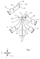
- Fig. 1 shows the overall structure of a device according to the invention, of the purpose Simplification of the description only shows the components essential to the invention or are explained. Further, generally known and for operating the device required drive and / or guide means as well as electrical / electronic Circuits are not shown or are only described in general terms.
- the device according to the invention essentially consists of a pair of C-formers 50, 50 ', which together form a flat, loop-shaped wire binding element 41 into a provisional one Bend C-shape 41c and from a pair of O-formers that bent into C-shape 41c loop-shaped wire binding element 41 in a closed O-shape 41o for loosening Bend sheet-like substrates 11 to brochures 10.
- a stack of sheet-like substrates 11, which have a plurality of holes 12 have the outer edges placed one on top of the other a substantially straight
- the passage for the loops S of the flat wire binding element 41 is in one Pliers 70 clamped.
- the sheet-like substrates could e.g. from the pliers 70 are delivered, especially if the device according to the invention becomes a parent system belongs.
- the tongs 70 are firmer Part of the device according to the invention, especially if it is in the Embodiment is a table device for loose binding of brochures 10.
- the C-formers 50, 50 ' are each attached to an axis 51, 51' and become such driven, guided and controlled so that they rotate around the respective axis 51, 51 'can perform, as indicated by the corresponding arrows in Fig. 1.
- stepper motors, guides and those known to those skilled in the art are not shown
- Control means are provided for both C-formers 50, 50 ', so that the C-formers 50, 50' are also controllable in the X and Y directions.
- Stepper motors allow particularly great flexibility in the control and Execution of the movement of the C-formers 50, 50 ', the same applies to the O-formers 60, 60'.
- the O-formers 60, 60 ' also have corresponding, not shown, the person skilled in the art known drives, guide devices and control means for rotary movements the respective axis 61, 61 'and along the X and Y directions. Beyond that Drives, guidance and control means for the O-formers 60, 60 'provided by means of the O-formers 60, 60 'can be moved in the Z direction.
- the ones used here Cartesian coordinates are indicated in the coordinate cross in Fig. 1.
- the C-formers 50, 50 ' have a geometry that enables centering and gripping of the allow loop-shaped wire binding element 41.
- lugs 52 for gripping, or jamming of the loop-shaped wire binding element 41 is provided as well
- Centering elements 53, 53 'and centering funnels 54, 54' are provided as well.
- the O-formers 60, 60 ' also have tabs 62, 62' which are used for clamping and Bend the loop-shaped wire binding element 41 in C-shape 41c serve in The following are described in more detail.
- the C-formers 50, 50 'with one another and O-formers 60, 60' with one another do not differ significantly from the structure except for the mirror symmetry, however in the following, in particular to describe the method according to the invention from a first C-former 50 and a second C-former 50 'and from a first O-former 60 and a second O-former 60 'spoken.
- the first C-formers 50, or first O-former 60 each characterized in that it is on the Side of the sheet-shaped printing materials 11 are arranged, on which the base side 41k of the loop-shaped wire binding element 41.
- the second C-former 50 ', or second O-former 60' are each characterized in that they are on the side of the sheet-shaped printing materials 11 on which the tips 41s of the Loops S of the loop-shaped wire binding element 41 lie.
- a loop-shaped wire binding element 41 with four loops S is shown in FIG. 2a.
- the loops S are at a distance A from tip 41s to tip 41s, and one Wire diameter D, a loop length L and a number N of loops S.
- the reference pages 41k and the reference pages 41s marked the loop tips of the wire binding element 41.
- the distance A corresponds to the distance A 'of the holes 12 in the sheet-like printing material 11 (see Fig. 4b).
- the number of holes N 'in the sheet-like printing material corresponds to as explained below, not necessarily the number N of loops S, but instead rather a maximum for the reasonable number N of loops S des Wire binding element 41.
- the loop length L gives the diameter of the wire binding element 41 in closed O-shape 41o and can depend on the number of sheet-like substrates 11 be made.
- the diameter of a wire binding element bent to form O-shape 41o 41 is chosen so that the bound brochure 10 is given an aesthetic appearance, is easy to turn and is easy to stack.
- 2b is a loop-shaped one Wire binding element 41 shown in C-shape 41c.
- the loop-shaped wire binding element 41 in C-form 41c represents an intermediate, as in a similar form to Manufacture of wire-o bindings can be purchased. However, is located in the device according to the invention and in the method according to the invention in Difference to the state of the art already a booklet to be bound within the Loops when the wire binding member 41 receives the C-shape 41c.
- FIG. 3 is a fully bound booklet 10 with one completely in an O-shape 41o bent wire binding element 41 shown, which has a continuous bond.
- Fig. 4a shows a single weave consisting of wire binding elements 41 ', each have only a single loop and exactly one for each hole 12 in the print carriers Wire binding element 41 'is used.
- a wire comb binding is shown in FIG. 4b which consists of several, for example multi-loop wire binding elements 41 ', the are spaced from one another in such a way that holes 12 remain free. Any other A combination of the above options is clear to the person skilled in the art.
- FIG. 5 shows details of the centering of a flat, loop-shaped wire binding element shown.
- these are centering funnels 54, 54 'into which the tips 41s of the flat, loop-shaped wire binding element can be inserted.
- To the others are wedge-shaped centering elements 53 (see also FIG. 6) which on the base side 41k of the wire binding element 41 between the ends of the loops S slide and thus fix the position of the loops S on the base side 41k.
- the Width of the portion of the centering elements 53 which between the legs of the Loop S is pushed essentially in such a way that the legs of the loop S are parallel to each other. As a result, the parallelism of the loops S supported each other.
- the lugs 52, 52 ' are used for Grasp and serve to clamp the loop-shaped wire binding element 41 to for all loops S of the wire binding element 41 continuous profiles, which in turn none have other movable components.
- the position of the wire binding element in these lugs 52, 52 ', as shown in Fig. 7, is fixed solely by clamping, wherein the clamping is achieved by turning the C-formers 50, 50 '.
- the Manufacturing effort comparatively low.
- FIG. 8. 8 shows the first C-former 50 in an insertion position.
- the lower nose flank 56 and the opposing clamping flank 55 are not yet in contact with the wire binding element 41.
- the first C-former 50 is in this insertion position when approaching a combing device held by the O-former 60, 60 'or a combing device, not shown flat wire binding element.
- the second C-former 50 ' is already shown in a clamping position in FIG.
- the second c-former 50 ' is pivoted counterclockwise about a pivot point P1' (see FIG.
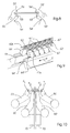
- the structure of the O-formers 60, 60 ' is shown schematically in FIG. 9.
- the O-formers 60, 60 ' have a number of individual bending elements 64, 64 ', each along one Groove 66, 66 'can be attached to the individual O-formers 60, 60'.
- each Bending element 64, 64 'each has a hook-shaped nose 62, 62' with a flat underside which is connected on one side to the bending element body of the bending element 64, 64 '.
- the hook-shaped lugs 62, 62 'of the bending elements on the first O-former 60 arranged in mirror image, so that all lugs of both O-formers 60, 60 'in the same Show direction.
- the length of the lugs 62, 62 ' is based on the loop shape of the wire binding element 41 customized. On the one hand, the lugs 62, 62 'on the inside are longer than the width of the Loops S, so that a loop S with a nose 62, 62 'is securely gripped can. On the other hand, the lugs 62, 62 'are shorter in their total length than the distance between two loops S.
- the O-formers 60, 60 ' have an additional drive in the Z direction fitted.
- the lugs 62, 62' first dip between the loops S one open and move wire binding element 41 inserted into the device according to the invention then in the Z direction over the loops to make them similar to the one described above Clamp movement of the C-former 50, 50 'by turning the O-former 60, 60' and to bend.
- the clamping and bending mechanism in the X-Y plane runs as above described.
- the clamping of a wire binding element 41 by turning the C-former 50, 50 'or O-formers 60, 60' can be rotated to the leaf-shaped Printing materials 11 out or away from the sheet-shaped printing materials 11 can be reached.
- FIG. 10 is a schematic representation of the position of the pivot points P1, P1 ', P2, P2' shown within the wire binding element. It should be noted that in FIG. 10 the pivot points are shown using a flat wire binding element 41, the However, the inner pivot points P2, P2 'of the O-formers 60, 60' are also in the case of a C-shape 41c bent wire binding element 41 according to FIG. 2b in a flat section of the Wire binding elements 41 are in a C-shape.
- the lugs 62, 62 'of the O-formers 60, 60' have the loop S in their clamped position opposite side chamfers 67, 67 '. These chamfers 67, 67 'facilitate the immersion of the Bending elements 64, 64 'between the loops.
- the motion sequences are from a, not shown, from the State of the art control for the different, also not shown stepper motors known to those skilled in the art for moving the C-former 50, 50 'and 60, 60' are responsible, controlled.
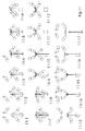
- the device according to the invention is in a basic position.
- Stacks of sheet-like printing materials 11 with aligned holes 12 are in the pliers 70 clamped so that the holes 12 of the sheet-like printing materials 11 in one Combing plane for the wire binding element 41 are located.
- the C-formers 50, 50 'are located are located above the combing level, the O-formers 60, 60 'are below the Combing plane and are according to the thickness of the booklet 10 to be bound spaced such that they are in the assumed position as a fanning out preventer act for the sheet-like printing materials 11, in particular if the pliers 70 the sheet-shaped printing materials 11 swings into the intended position from below.
- individual spread sheet-like printing materials 11 are spread apart aligned.
- the second C-former 60 moves into the centering position for the flat loop-shaped wire binding element 41, as shown in Fig. 11-2.
- the second C-former is in the centering position when the centering funnel 65 'of the second C-former 50 'are aligned with the holes 12 of the sheet-like printing materials 11.
- the O-formers 60, 60 'move together in the X direction below the combing plane the sheet-shaped substrates 11 are aligned. Subsequently, a level Wire binding element 41 through the holes 12 in the sheet-shaped printing materials 11 threaded / combed.
- the loop-shaped wire binding element 41 is by Stop with the tips 41s in the centering funnels 65 'of the second C-former 50' inserted.
- the wire binding element 41 with a Combing device held in this position manual insertion of the Wire binding element 41 is also possible.
- this can also be a plurality of wire binding elements 41, 41 ', 41 "act as described above and shown in Figures 4a and 4b.
- a single wire binding element 41 is always assumed below, although a plurality of wire binding elements 41, 41 ', 41 "for the invention Procedure does not make a difference.
- the O-formers 60, 60 'then move in the X direction to the correct engagement point for the C-shape to be manufactured 41c.
- This C-shape 41c to be manufactured depends in particular on from the loop length S, and in turn from the diameter of the finished O-shape and thus on the thickness of the booklet 10 to be bound. Then move the O-formers 60, 60 'in the Z direction with their lugs 62, 62' over the loops S until the Noses 62, 62 'cover the loops S in width.
- a combing device can be removed or that Wire binding element 41 can be released in another way, as it is for the rest of the inventive method except for the exact centering of the Wire binding element 41 within the device according to the invention always through the C-former 50, 50 'or the O-former 60, 60' is fixed in position.
- the first C-former 50 is shown in FIG. 11-5 Centering position moved in the Y direction.
- the first C-former 50 is in one Centering position when the wedge-shaped centering elements 53 on the base side 41k of the wire binding element 41 in the spaces between the legs of the loops S des Retract wire binding element 41.
- the O-formers 60, 60 'then release the jam of the wire binding elements 41 now in C-shape 41c move the bending positions corresponding to the pivot points P2, P2 'and in turn clamp the Wire binding element 41 (see Fig. 11-11).
- the C-formers 50, 50 'then move back to the position shown in FIGS. 11-12, where the C-formers 50, 50 'follow the same curve as when bending the Wire binding element 41, but in the opposite direction, until the C-shape 41c bent wire binding element 41 is present in the tension-free state. Then the C-formers turn 50, 50 'around the pivot points P1 and P1' to the clamping by the To release clamping flanks 55, 55 'or nose flanks 56, 56'.
- the C-formers 50, 50 'then move out of the wire binding element 41 in a C-shape 41c out and into a parking position above the meshing level, as shown in Fig. 11-13. there the parking position is selected such that the C-formers 50, 50 'are outside the movement space the O-formers 60, 60 'are in the O-form.
- the wire binding element 41 is bent over to the elastic Compensate spring back of the wire, so that the wire binding element 41 in stress-free state in the desired shape.
- the O-formers 60, 60 'then move back into the position shown in FIGS. 11-15, where the 0-formers 60, 60 'follow the same curve as when bending the Wire binding element 41, but in the opposite direction until the O-shape 41o bent wire binding element 41 is present in the tension-free state. Then the O-formers turn 60, 60 'around the pivots P2 or P2' to the clamping by the To release bending elements 64, 64 '.
- the brochure can be obtained from the invention
- the device can be pulled out or removed manually.
- C-formers 50, 50 'or O-formers 60, 60' essentially not of the loop length S dependent, but only through the possibilities to move on designated Guided tours limited.
- the adaptation to the loop length L of the wire binding element 41 happens via the position and movement curves of the C-formers 50, 50 'and O-formers 60, 60 '.
- a limitation of the loop length S downward represents the size of the lugs 62, 62 'of the O-formers 60, 60', which are closed within the O-form 41o Wire binding element must have space together with the spine. Since the sheet-like substrates 11 in the brochure 10 but also in the bound state technically there is practically no restriction for the format a booklet 10 to be bound.
Landscapes
- Engineering & Computer Science (AREA)
- Textile Engineering (AREA)
- Mechanical Engineering (AREA)
- Sheet Holders (AREA)
- Folding Of Thin Sheet-Like Materials, Special Discharging Devices, And Others (AREA)
- Wire Processing (AREA)
Abstract
Description
- Fig. 1
- eine Prinzipskizze des Aufbaus einer Ausführungsform der erfindungsgemäßen Vorrichtung;
- Fig. 2a
- eine Darstellung eines ebenen schlaufenförmigen Drahtbindeelements;
- Fig. 2b
- eine Darstellung eines schlaufenförmigen Drahtbindeelements in C-Form;
- Fig. 3
- eine Ausführungsform einer gebundenen Broschüre mittels eines durchgängigen in O-Form gebogenen schlaufenförmigen Drahtbindeelements;
- Fig. 4a
- eine Ausführungsform einer gebundenen Broschüre mittels mehrerer Einzeldrahtbindeelemente;
- Fig. 4b
- eine Ausführungsform einer gebundenen Broschüre mittels mehrerer in Abständen zueinander angeordneten Einzeldrahtbindeelemente;
- Fig. 5
- eine schematische Darstellung der C-Former beim Zentrieren der Spitzen des Drahtbindelements;
- Fig. 6
- eine schematische Darstellung der C-Former beim Zentrieren der Basisseite des Drahtbindelements;
- Fig. 7
- eine schematische Darstellung der C-Former mit einem in die Nasen eingelegten Drahtbindelement;
- Fig. 8
- Prinzipskizze der Einlege bzw. Klemmposition der C-Former;
- Fig. 9
- eine schematische Darstellung der O-Former;
- Fig. 10
- schematische Darstellung der Drehpunkte der C- und O-Former innerhalb des schlaufenförmigen Drahtbindelements;
- Fig. 11
- eine schematische Darstellung des erfindungsgemäßen Verfahrensablaufs.
In Fig. 8 ist der erste C-Former 50 in einer Einlegeposition gezeigt. Die untere Nasenflanke 56 und die gegenüberliegende Klemmflanke 55 befinden sich noch nicht in Kontakt mit dem Drahtbindeelement 41. Der erste C-Former 50 befindet sich in dieser Einlegeposition beim Anfahren an einen durch die O-Former 60, 60' oder eine nicht gezeigte Einkämmvorrichtung gehaltenes ebenes Drahtbindeelement. Der zweite C-Former 50' ist in Fig.8 bereits in einer Klemmposition gezeigt. Dazu wird der zweite c-Former 50' um einen Drehpunkt P1' (vergleiche Fig. 10) relativ zur Einlegeposition gegen den Uhrzeigersinn verschwenkt, bis die untere Nasenflanke 66' und die Klemmflanke 65' des zweiten C-Formers 50' zunächst in Kontakt mit dem ebenen Drahtbindeelement 41 treten und bei weiterer Verschwenkung, in diesem Fall gegen den Uhrzeigersinn, ein ausreichend großer Druck zwischen den Flanken 65', 66' und dem Drahtbindeelement aufgebaut wird, so dass das Drahtbindeelement 41 nicht mehr verrutschen kann.
- 10
- Broschüre
- 11
- blattförmige Bedruckstoffe
- 12
- Lochung/Löcher
- 41
- Drahtbindeelement
- 41'
- Einzeldrahtbindeelemente
- 41"
- Drahtteppich
- 41k
- Basisseite der Schlaufe
- 41c
- C-Form des Drahtbindeelements
- 41o
- O-Form des Drahtbindeelements
- 41s
- Spitze der Schlaufe
- 50
- Erster C-Former
- 50'
- Zweiter C-Former
- 51, 51'
- Achse
- 52, 52'
- Nase
- 53, 53'
- Zentrierungselement
- 54, 54'
- Zentrierungstrichter
- 55, 55'
- Klemmflanke
- 56, 56'
- Nasenflanke
- 60
- Erster O-Former
- 60'
- Zweiter O-Former
- 61, 61'
- Achse
- 62, 62'
- Nase
- 64, 64'
- Biegeelement
- 66, 66'
- Nut
- 67, 67'
- Fase
- 70
- Haltezange
- 80
- Transportzange
- A, A'
- Schlaufenabstand
- D
- Drahtdurchmesser
- S
- Schlaufen
- L
- Schlaufenlänge
- N, N'
- Anzahl der Schlaufen
- P1, P1'
- Drehpunkt C-Former
- P2, P2'
- Drehpunkt O-Former
- X
- X - Richtung eines kartesischen Koordinatensystems
- Y
- Y - Richtung eines kartesischen Koordinatensystems
- Z
- Z - Richtung eines kartesischen Koordinatensystems
Claims (23)
- Vorrichtung zum losen Verbinden von blattförmigen Bedruckstoffen (11) zu Broschüren (10) mittels eines schlaufenförmigen Drahtbindeelements (41), mit zwei C-Formern (50, 50'), wobei die C-Former (50, 50') derart gelagert sind, dass das anfangs ebene, schlaufenförmige Drahtbindeelement (41) in eine im Wesentlichen kontinuierlich kreisbogenartige C-Form (41c) gebogen wird, sowie mit zwei O-Formern (60, 60'), wobei die O-Former (60, 60') derart gelagert sind, dass das in C-Form (41c) gebogene schlaufenförmige Drahtbindeelement (41) in eine geschlossene Form (41o) gebogen wird.
- Vorrichtung nach Anspruch 1,
dadurch gekennzeichnet, dass unterschiedliche Schlaufenlänge (S) gebogen werden können, ohne dass eine Umrüstung an der Vorrichtung vorgenommen werden muss. - Vorrichtung nach einem der Ansprüche 1 bis 2,
dadurch gekennzeichnet, dass die C-Former (50, 50') Klemmflanken (55, 55') und Nasen (52, 52') aufweisen, wobei diese Nasen mit einer Nasenflanke (56, 56') ausgestattet ist, wobei Nasenflanken (56, 56') und Klemmflanken (55, 55') zusammenwirken, um das schlaufenförmigen Drahtbindeelements (41) zu klemmen. - Vorrichtung nach einem der Ansprüche 1 bis 3,
dadurch gekennzeichnet, dass eine Verklemmung des schlaufenförmigen Drahtbindeelements (41) beim C-Formen allein durch die Biegebewegung der C-Former (50, 50') erzeugt wird. - Vorrichtung nach einem der Ansprüche 1 bis 4,
dadurch gekennzeichnet, dass die C-Former (50, 50') Zentrierungselemente (53, 53') für die Zentrierung des ebenen, schlaufenförmigen Drahtbindeelements (41) innerhalb der Broschüre (10) aufweisen. - Vorrichtung nach einem der Ansprüche 1 bis 5,
dadurch gekennzeichnet, dass die C-Former (50, 50') jeweils Antriebe für eine Drehbewegung, sowie Antriebe für Bewegung in X-Richtung und Y-Richtung aufweisen, sowie eine Steuerung zur Ansteuerung der Bewegung der C-Former (50, 50'). - Vorrichtung nach Anspruch 6,
dadurch gekennzeichnet, dass die Steuerung die Antriebe der C-Former (50, 50') beim Biegen des ebenen schlaufenförmigen Drahtbindeelements (41) in eine C-Form (41c) derart steuert, so dass der Drehpunkt der Bewegung der einzelnen C-Former (50, 50') innerhalb des schlaufenförmigen Drahtbindeelements (41) liegt. - Vorrichtung nach einem der Ansprüche 1 bis 7,
dadurch gekennzeichnet, dass die Bewegung des beiden C-Former (50, 50') während des Biegevorgangs synchron zueinander verläuft. - Vorrichtung nach einem der Ansprüche 1 bis 8,
dadurch gekennzeichnet, dass die O-Former (60, 60') senkrecht zur Schlaufenrichtung des schlaufenförmigen Drahtbindeelements (41) Nasen (62, 62') aufweisen, wobei die Nasen (62, 62') kürzer sind als der Abstand zweier Schlaufen (S) des schlaufenförmigen Drahtbindeelements (41). - Vorrichtung nach einem der Ansprüche 1 bis 9,
dadurch gekennzeichnet, dass die O-Former (60, 60') jeweils Antriebe für eine Drehbewegung, sowie Antriebe fiir Bewegung in X-Richtung und Y-Richtung aufweisen, sowie eine Steuerung zur Ansteuerung der Bewegung der O-Former (60, 60'). - Vorrichtung nach Anspruch 10,
dadurch gekennzeichnet, dass die Steuerung die Antriebe der O-Former (60, 60') beim Biegen des ebenen schlaufenförmigen Drahtbindeelements (41) in eine O-Form (41o) derart steuert, so dass der Drehpunkt der beiden O-Former (60, 60') innerhalb des schlaufenförmigen Drahtbindeelements (41) liegt. - Vorrichtung nach einem der Ansprüche 1 bis 11,
dadurch gekennzeichnet, dass die Bewegung der beiden O-Former (60, 60') während des Biegevorgangs synchron zueinander verläuft. - Vorrichtung nach einem der Ansprüche 1 bis 2,
dadurch gekennzeichnet, dass die O-Former (60, 60') jeweils einen Antrieb zur Bewegung in Z-Richtung aufweisen, sowie Steuerungsmittel zur Steuerung der Bewegung in Z-Richtung. - Vorrichtung nach einem der Ansprüche 1 bis 13,
dadurch gekennzeichnet, dass das eine Verklemmung des schlaufenförmigen Drahtbindeelements (41) beim O-Formen allein durch die Biegebewegung der O-Former (60, 60') erzeugt wird. - Vorrichtung nach einem der Ansprüche 1 bis 14,
dadurch gekennzeichnet, dass eine Steuerung Geschwindigkeitsprofile für die Bewegung der C-Former (50, 50') und O-Former (60, 60') für unterschiedliche Schlaufenlängen (L) des ebenen, schlaufenförmigen Drahtbindeelements (41) bestimmt, so dass ein schlaufenförmiges Drahtbindeelement (41) in O-Form (410) mit entsprechendem Durchmesser zusammengebogen wird. - Vorrichtung nach einem der Ansprüche 1 bis 15,
dadurch gekennzeichnet, dass das schlaufenförmige Drahtbindeelement (41) durch die C-Former (50, 50') und/oder O-Former (60, 60') derart überbogen werden, so dass sich das schlaufenförmige Drahtbindeelement (41) bei Entlastung in die gewünschte Form entspannt. - Vorrichtung nach einem der Ansprüche 1 bis 16,
dadurch gekennzeichnet, dass die beiden O-Former (60, 60') mindestens für jede einzelne Schlaufe des Drahtbindeelements (41) jeweils einzelne Biegeelemente (64, 64') aufweisen, die an dem O-Former (60, 60') auswechselbar befestigt sind. - Verfahren zum losen Binden von aus mit Löchern (12) versehenen blattförmigen Bedruckstoffen (11) zusammengesetzten Broschüren (10), mittels mindestens einem schlaufenförmigen Drahtbindeelement (41), mit den Schritten:a) Einbringen des anfangs ebenen, schlaufenförmigen Drahtbindeelements (41) durch Löcher (12) der blattförmigen Bedruckstoffe (11),b) Biegen des ebenen, schlaufenförmigen Drahtbindeelements (41) in eine kontinuierlich kreisbogenartige C-Form (41c) mit zwei C-Formern (50, 50'),c) Biegen des schlaufenförmigen Drahtbindeelements (41) in C-Form (41c) in eine geschlossene O-Form (410) mit zwei O-Formern (60, 60').
- Verfahren nach Anspruch 18,
dadurch gekennzeichnet, dass das Verfahren unabhängig von der Schlaufenlänge (L) des ebenen schlaufenförmigen Drahtbindeelements (41) durchgeführt werden kann. - Verfahren nach einem der Ansprüche 18 bis 19,
dadurch gekennzeichnet, dass eine Verklemmung des schlaufenförmigen Drahtbindeelements (41) beim C-Formen allein durch die Biegebewegung der C-Former (50, 50') erzeugt wird. - Verfahren nach einem der Ansprüche 18 bis 20,
dadurch gekennzeichnet, dass eine Verklemmung des schlaufenförmigen Drahtbindeelements (41) beim O-Formen allein durch die Biegebewegung der O-Former (60, 60') erzeug wird. - Verfahren nach einem der Ansprüche 18 bis 21,
dadurch gekennzeichnet, dass beim Verbiegen des schlaufenförmigen Drahtbindeelements (41) in eine C-Form und / oder O-Form der Drehpunkt innerhalb des schlaufenförmigen Drahtbindeelements (41) liegt. - Verfahren nach einem der Ansprüche 18 bis 22,
dadurch gekennzeichnet, dass beim Verbiegen des schlaufenförmigen Drahtbindeelements (41) in eine O-Form der Drehpunkt innerhalb des schlaufenförmigen Drahtbindeelements (41) liegt.
Applications Claiming Priority (2)
| Application Number | Priority Date | Filing Date | Title |
|---|---|---|---|
| DE10223481A DE10223481A1 (de) | 2002-05-27 | 2002-05-27 | Verfahren zum Biegen von Drahtkammbindeelementen |
| DE10223481 | 2002-05-27 |
Publications (2)
| Publication Number | Publication Date |
|---|---|
| EP1378371A1 true EP1378371A1 (de) | 2004-01-07 |
| EP1378371B1 EP1378371B1 (de) | 2011-06-15 |
Family
ID=29432337
Family Applications (1)
| Application Number | Title | Priority Date | Filing Date |
|---|---|---|---|
| EP03008891A Expired - Lifetime EP1378371B1 (de) | 2002-05-27 | 2003-04-30 | Verfahren zum Biegen von Drahtkammbindeelementen |
Country Status (6)
| Country | Link |
|---|---|
| US (1) | US20040052615A1 (de) |
| EP (1) | EP1378371B1 (de) |
| JP (1) | JP2004001525A (de) |
| CN (1) | CN1461706A (de) |
| AT (1) | ATE512804T1 (de) |
| DE (1) | DE10223481A1 (de) |
Cited By (1)
| Publication number | Priority date | Publication date | Assignee | Title |
|---|---|---|---|---|
| US9862221B2 (en) | 2011-07-18 | 2018-01-09 | ACCO Brands Corporation | Binding system for retaining bound components |
Families Citing this family (8)
| Publication number | Priority date | Publication date | Assignee | Title |
|---|---|---|---|---|
| US20020085897A1 (en) * | 2000-11-29 | 2002-07-04 | Thomas Blattner | Binding process for manufacturing brochures |
| US7661918B2 (en) * | 2003-05-30 | 2010-02-16 | General Binding Corporation | Binding machine and method |
| WO2006017255A1 (en) * | 2004-07-12 | 2006-02-16 | General Binding Corporation | Binding element and plurality of binding elements particularly suited for automated processes |
| US8123448B2 (en) | 2005-08-16 | 2012-02-28 | General Binding Corporation | Apparatus and methods for automatically binding a stack of sheets with a nonspiral binding element |
| USD620977S1 (en) | 2006-08-04 | 2010-08-03 | General Binding Corporation | Binding element |
| JP4949160B2 (ja) * | 2006-09-15 | 2012-06-06 | 株式会社リコー | リングバインド制御装置、リングバインド制御方法及びリングバインド制御プログラム |
| JP4956508B2 (ja) * | 2008-08-18 | 2012-06-20 | 渡辺通商株式会社 | 紙製綴じ具を用いた冊子の製造装置 |
| JP6800746B2 (ja) * | 2016-12-28 | 2020-12-16 | キヤノン株式会社 | 画像形成装置、画像形成装置の制御方法、及びプログラム |
Citations (5)
| Publication number | Priority date | Publication date | Assignee | Title |
|---|---|---|---|---|
| DE1814632A1 (de) * | 1967-12-15 | 1969-07-10 | Burn & Co Ltd James | Verfahren und Vorrichtung zum Herstellen eines aus aneinandergereihten gebogenen Drahtzinken bestehenden schlauchartigen Drahtbandes zum Heften von perforierten Blaettern |
| DE2325867A1 (de) * | 1972-05-26 | 1973-12-06 | Cartiere Paolo Pigna Spa | Vorrichtung zum binden eines perforierten blaetterstapels |
| DE2847700A1 (de) * | 1978-11-03 | 1980-05-14 | Will E C H Gmbh & Co | Verfahren und vorrichtung zum herstellen einer drahtbindung fuer bloecke, kalender usw. |
| DE3141686A1 (de) * | 1980-11-08 | 1982-06-16 | Womako Maschinenkonstruktionen GmbH, 7440 Nürtingen | Verfahren und vorrichtung zum herstellen von bloecken mit drahtkammbindung |
| EP1211000A2 (de) * | 2000-11-29 | 2002-06-05 | Heidelberger Druckmaschinen Aktiengesellschaft | Verfahren zum sementartigen Biegen von Drahtbindeelementen |
Family Cites Families (12)
| Publication number | Priority date | Publication date | Assignee | Title |
|---|---|---|---|---|
| DE1436067A1 (de) * | 1965-04-08 | 1969-04-17 | Cartiere Paolo Pigna Spa | Verfahren und Vorrichtung zum stetigen und automatischen Spiralheften loser perforierter Blaetter |
| US3451081A (en) * | 1968-01-03 | 1969-06-24 | Burn & Co Ltd James | Book-binding machines |
| US3839759A (en) * | 1971-08-09 | 1974-10-08 | Gen Binding Corp | Method and apparatus for binding books |
| US4047544A (en) * | 1976-12-27 | 1977-09-13 | The Mead Corporation | Wire forming apparatus |
| EP0095245B1 (de) * | 1982-05-21 | 1991-04-03 | James Burn International Limited | Maschinen zum Binden mittels Draht |
| EP0095243A1 (de) * | 1982-05-21 | 1983-11-30 | James Burn Bindings Limited | Drahtbindemaschinen |
| GB2213769B (en) * | 1987-12-22 | 1992-01-02 | Burn James Int Ltd | Improvements in and relating to the binding of perforated sheets |
| DE4002144A1 (de) * | 1990-01-25 | 1991-08-01 | Renz Chr Gmbh & Co | Schliessvorrichtung fuer bindekaemme |
| GB2301553B (en) * | 1995-05-04 | 1999-03-10 | Burn James Int Ltd | Improvements in and relating to a binding apparatus |
| DE10141811A1 (de) * | 2001-08-27 | 2003-03-20 | Heidelberger Druckmasch Ag | Vorrichtung zum flexiblen Herstellen von Drahtbindeelementen für das Binden von Broschüren beliebiger Formate und Dicken mittels Drahtkammbindung |
| US20020085897A1 (en) * | 2000-11-29 | 2002-07-04 | Thomas Blattner | Binding process for manufacturing brochures |
| DE10059344A1 (de) * | 2000-11-29 | 2002-06-06 | Heidelberger Druckmasch Ag | Verfahren zum Herstellen von Broschüren beliebiger Formate und Dicken mittels Drahtkammbindung |
-
2002
- 2002-05-27 DE DE10223481A patent/DE10223481A1/de not_active Withdrawn
-
2003
- 2003-04-30 AT AT03008891T patent/ATE512804T1/de active
- 2003-04-30 EP EP03008891A patent/EP1378371B1/de not_active Expired - Lifetime
- 2003-05-22 US US10/443,521 patent/US20040052615A1/en not_active Abandoned
- 2003-05-26 CN CN03138286A patent/CN1461706A/zh active Pending
- 2003-05-27 JP JP2003149662A patent/JP2004001525A/ja active Pending
Patent Citations (5)
| Publication number | Priority date | Publication date | Assignee | Title |
|---|---|---|---|---|
| DE1814632A1 (de) * | 1967-12-15 | 1969-07-10 | Burn & Co Ltd James | Verfahren und Vorrichtung zum Herstellen eines aus aneinandergereihten gebogenen Drahtzinken bestehenden schlauchartigen Drahtbandes zum Heften von perforierten Blaettern |
| DE2325867A1 (de) * | 1972-05-26 | 1973-12-06 | Cartiere Paolo Pigna Spa | Vorrichtung zum binden eines perforierten blaetterstapels |
| DE2847700A1 (de) * | 1978-11-03 | 1980-05-14 | Will E C H Gmbh & Co | Verfahren und vorrichtung zum herstellen einer drahtbindung fuer bloecke, kalender usw. |
| DE3141686A1 (de) * | 1980-11-08 | 1982-06-16 | Womako Maschinenkonstruktionen GmbH, 7440 Nürtingen | Verfahren und vorrichtung zum herstellen von bloecken mit drahtkammbindung |
| EP1211000A2 (de) * | 2000-11-29 | 2002-06-05 | Heidelberger Druckmaschinen Aktiengesellschaft | Verfahren zum sementartigen Biegen von Drahtbindeelementen |
Cited By (2)
| Publication number | Priority date | Publication date | Assignee | Title |
|---|---|---|---|---|
| US9862221B2 (en) | 2011-07-18 | 2018-01-09 | ACCO Brands Corporation | Binding system for retaining bound components |
| US10569590B2 (en) | 2011-07-18 | 2020-02-25 | ACCO Brands Corporation | Binding system for retaining bound components |
Also Published As
| Publication number | Publication date |
|---|---|
| CN1461706A (zh) | 2003-12-17 |
| ATE512804T1 (de) | 2011-07-15 |
| JP2004001525A (ja) | 2004-01-08 |
| US20040052615A1 (en) | 2004-03-18 |
| EP1378371B1 (de) | 2011-06-15 |
| DE10223481A1 (de) | 2003-12-11 |
Similar Documents
| Publication | Publication Date | Title |
|---|---|---|
| EP2697008B1 (de) | Verfahren und federmaschine zur herstellung von federn | |
| EP2239067B1 (de) | Federherstellungsmaschine | |
| EP2177287A2 (de) | Stützbackenanordnung zum gleitenden seitlichen Abstützen von stab- und rohrförmigen Werkstücken an Biegemaschinen | |
| DE2825903C3 (de) | Vorrichtung zum Ineinanderfalten von mehreren Bahnen | |
| EP1211000A2 (de) | Verfahren zum sementartigen Biegen von Drahtbindeelementen | |
| EP2923852B1 (de) | Vorrichtung zum formen von buchdecken | |
| EP1378371B1 (de) | Verfahren zum Biegen von Drahtkammbindeelementen | |
| DE202020002598U1 (de) | Biegemaschine zum Biegen eines Werkstücks aus Flachmaterial und Steuereinheit für eine solche Biegemaschine | |
| EP1064110A1 (de) | Biegemaschine | |
| DE102022100485A1 (de) | Fertigungsanlage des Positionierungsbaustahlgewebes für vorgefertigte Hohlkästen der Eisenbahn | |
| EP3551356B1 (de) | Fertigungsanlage mit einem klemmwerkzeug sowie verfahren zur anpassung einer gesamtlänge einer biegekante des klemmwerkzeugs | |
| EP0774310A1 (de) | Transfereinrichtung für Federn zu einer Montagemaschine | |
| DE19824741C2 (de) | Verfahren und Vorrichtung zur Herstellung von Bundlagern | |
| WO2005021181A1 (de) | Verfahren und vorrichtung zum herstellen eines gitterträgers | |
| EP0662044B1 (de) | Vorrichtung zum herstellen einer schutzauflage für klosettsitze | |
| DE69703978T2 (de) | Vorrichtung zum regeln der grösse eines werkzeugmaschinen-blechhalters | |
| EP1348574B1 (de) | Verfahren und Vorrichtung zum Ausrichten eines Stapels | |
| EP2380676A1 (de) | Verfahren zum Betrieb einer Biegemaschine mit verfahrbarer Richteinheit | |
| DE10246074A1 (de) | Vorrichtung und Verfahren zur Handhabung von ebenen Drahtbindeelementvorformen | |
| EP2149410A1 (de) | Verfahren zur maschinellen Herstellung einer Bewehrungsmatte, Bewehrungsmatte und Schweisseinrichtung | |
| DE2653759A1 (de) | Verfahren und vorrichtung zum ausrichten von nutzen | |
| EP3199369B1 (de) | Verfahren zum vorformen und runden eines buchblocks | |
| DE102019119848A1 (de) | Werkzeug und Verfahren zum Bearbeiten von plattenförmigen Werkstücken, insbesondere Blechen | |
| DE102020107192B3 (de) | Vorrichtung zum Biegen mindestens eines in einem Ausgangszustand U-förmigen Leiterstücks und ein entsprechendes Verfahren | |
| EP1324841B1 (de) | Vorrichtung zum biegen einer materialbahn |
Legal Events
| Date | Code | Title | Description |
|---|---|---|---|
| PUAI | Public reference made under article 153(3) epc to a published international application that has entered the european phase |
Free format text: ORIGINAL CODE: 0009012 |
|
| AK | Designated contracting states |
Kind code of ref document: A1 Designated state(s): AT BE BG CH CY CZ DE DK EE ES FI FR GB GR HU IE IT LI LU MC NL PT RO SE SI SK TR |
|
| AX | Request for extension of the european patent |
Extension state: AL LT LV MK |
|
| 17P | Request for examination filed |
Effective date: 20040707 |
|
| AKX | Designation fees paid |
Designated state(s): AT BE BG CH CY CZ DE DK EE ES FI FR GB GR HU IE IT LI LU MC NL PT RO SE SI SK TR |
|
| GRAP | Despatch of communication of intention to grant a patent |
Free format text: ORIGINAL CODE: EPIDOSNIGR1 |
|
| GRAS | Grant fee paid |
Free format text: ORIGINAL CODE: EPIDOSNIGR3 |
|
| GRAA | (expected) grant |
Free format text: ORIGINAL CODE: 0009210 |
|
| AK | Designated contracting states |
Kind code of ref document: B1 Designated state(s): AT BE BG CH CY CZ DE DK EE ES FI FR GB GR HU IE IT LI LU MC NL PT RO SE SI SK TR |
|
| REG | Reference to a national code |
Ref country code: GB Ref legal event code: FG4D Free format text: NOT ENGLISH Ref country code: CH Ref legal event code: EP |
|
| REG | Reference to a national code |
Ref country code: IE Ref legal event code: FG4D Free format text: LANGUAGE OF EP DOCUMENT: GERMAN |
|
| REG | Reference to a national code |
Ref country code: DE Ref legal event code: R096 Ref document number: 50313758 Country of ref document: DE Effective date: 20110721 |
|
| REG | Reference to a national code |
Ref country code: NL Ref legal event code: VDEP Effective date: 20110615 |
|
| PG25 | Lapsed in a contracting state [announced via postgrant information from national office to epo] |
Ref country code: SE Free format text: LAPSE BECAUSE OF FAILURE TO SUBMIT A TRANSLATION OF THE DESCRIPTION OR TO PAY THE FEE WITHIN THE PRESCRIBED TIME-LIMIT Effective date: 20110615 |
|
| PG25 | Lapsed in a contracting state [announced via postgrant information from national office to epo] |
Ref country code: CY Free format text: LAPSE BECAUSE OF FAILURE TO SUBMIT A TRANSLATION OF THE DESCRIPTION OR TO PAY THE FEE WITHIN THE PRESCRIBED TIME-LIMIT Effective date: 20110615 Ref country code: GR Free format text: LAPSE BECAUSE OF FAILURE TO SUBMIT A TRANSLATION OF THE DESCRIPTION OR TO PAY THE FEE WITHIN THE PRESCRIBED TIME-LIMIT Effective date: 20110916 Ref country code: SI Free format text: LAPSE BECAUSE OF FAILURE TO SUBMIT A TRANSLATION OF THE DESCRIPTION OR TO PAY THE FEE WITHIN THE PRESCRIBED TIME-LIMIT Effective date: 20110615 Ref country code: FI Free format text: LAPSE BECAUSE OF FAILURE TO SUBMIT A TRANSLATION OF THE DESCRIPTION OR TO PAY THE FEE WITHIN THE PRESCRIBED TIME-LIMIT Effective date: 20110615 |
|
| PG25 | Lapsed in a contracting state [announced via postgrant information from national office to epo] |
Ref country code: NL Free format text: LAPSE BECAUSE OF FAILURE TO SUBMIT A TRANSLATION OF THE DESCRIPTION OR TO PAY THE FEE WITHIN THE PRESCRIBED TIME-LIMIT Effective date: 20110615 |
|
| REG | Reference to a national code |
Ref country code: IE Ref legal event code: FD4D |
|
| PG25 | Lapsed in a contracting state [announced via postgrant information from national office to epo] |
Ref country code: PT Free format text: LAPSE BECAUSE OF FAILURE TO SUBMIT A TRANSLATION OF THE DESCRIPTION OR TO PAY THE FEE WITHIN THE PRESCRIBED TIME-LIMIT Effective date: 20111017 Ref country code: EE Free format text: LAPSE BECAUSE OF FAILURE TO SUBMIT A TRANSLATION OF THE DESCRIPTION OR TO PAY THE FEE WITHIN THE PRESCRIBED TIME-LIMIT Effective date: 20110615 Ref country code: IE Free format text: LAPSE BECAUSE OF FAILURE TO SUBMIT A TRANSLATION OF THE DESCRIPTION OR TO PAY THE FEE WITHIN THE PRESCRIBED TIME-LIMIT Effective date: 20110615 Ref country code: CZ Free format text: LAPSE BECAUSE OF FAILURE TO SUBMIT A TRANSLATION OF THE DESCRIPTION OR TO PAY THE FEE WITHIN THE PRESCRIBED TIME-LIMIT Effective date: 20110615 |
|
| PG25 | Lapsed in a contracting state [announced via postgrant information from national office to epo] |
Ref country code: SK Free format text: LAPSE BECAUSE OF FAILURE TO SUBMIT A TRANSLATION OF THE DESCRIPTION OR TO PAY THE FEE WITHIN THE PRESCRIBED TIME-LIMIT Effective date: 20110615 Ref country code: RO Free format text: LAPSE BECAUSE OF FAILURE TO SUBMIT A TRANSLATION OF THE DESCRIPTION OR TO PAY THE FEE WITHIN THE PRESCRIBED TIME-LIMIT Effective date: 20110615 |
|
| PLBE | No opposition filed within time limit |
Free format text: ORIGINAL CODE: 0009261 |
|
| STAA | Information on the status of an ep patent application or granted ep patent |
Free format text: STATUS: NO OPPOSITION FILED WITHIN TIME LIMIT |
|
| 26N | No opposition filed |
Effective date: 20120316 |
|
| PG25 | Lapsed in a contracting state [announced via postgrant information from national office to epo] |
Ref country code: IT Free format text: LAPSE BECAUSE OF FAILURE TO SUBMIT A TRANSLATION OF THE DESCRIPTION OR TO PAY THE FEE WITHIN THE PRESCRIBED TIME-LIMIT Effective date: 20110615 |
|
| PG25 | Lapsed in a contracting state [announced via postgrant information from national office to epo] |
Ref country code: DK Free format text: LAPSE BECAUSE OF FAILURE TO SUBMIT A TRANSLATION OF THE DESCRIPTION OR TO PAY THE FEE WITHIN THE PRESCRIBED TIME-LIMIT Effective date: 20110615 |
|
| REG | Reference to a national code |
Ref country code: DE Ref legal event code: R097 Ref document number: 50313758 Country of ref document: DE Effective date: 20120316 |
|
| BERE | Be: lapsed |
Owner name: HEIDELBERGER DRUCKMASCHINEN A.G. Effective date: 20120430 |
|
| PG25 | Lapsed in a contracting state [announced via postgrant information from national office to epo] |
Ref country code: MC Free format text: LAPSE BECAUSE OF NON-PAYMENT OF DUE FEES Effective date: 20120430 |
|
| REG | Reference to a national code |
Ref country code: CH Ref legal event code: PL |
|
| GBPC | Gb: european patent ceased through non-payment of renewal fee |
Effective date: 20120430 |
|
| REG | Reference to a national code |
Ref country code: FR Ref legal event code: ST Effective date: 20121228 |
|
| PG25 | Lapsed in a contracting state [announced via postgrant information from national office to epo] |
Ref country code: BE Free format text: LAPSE BECAUSE OF NON-PAYMENT OF DUE FEES Effective date: 20120430 Ref country code: CH Free format text: LAPSE BECAUSE OF NON-PAYMENT OF DUE FEES Effective date: 20120430 Ref country code: LI Free format text: LAPSE BECAUSE OF NON-PAYMENT OF DUE FEES Effective date: 20120430 Ref country code: GB Free format text: LAPSE BECAUSE OF NON-PAYMENT OF DUE FEES Effective date: 20120430 |
|
| PG25 | Lapsed in a contracting state [announced via postgrant information from national office to epo] |
Ref country code: FR Free format text: LAPSE BECAUSE OF NON-PAYMENT OF DUE FEES Effective date: 20120430 |
|
| PG25 | Lapsed in a contracting state [announced via postgrant information from national office to epo] |
Ref country code: ES Free format text: LAPSE BECAUSE OF FAILURE TO SUBMIT A TRANSLATION OF THE DESCRIPTION OR TO PAY THE FEE WITHIN THE PRESCRIBED TIME-LIMIT Effective date: 20110926 |
|
| REG | Reference to a national code |
Ref country code: AT Ref legal event code: MM01 Ref document number: 512804 Country of ref document: AT Kind code of ref document: T Effective date: 20120430 |
|
| PG25 | Lapsed in a contracting state [announced via postgrant information from national office to epo] |
Ref country code: BG Free format text: LAPSE BECAUSE OF FAILURE TO SUBMIT A TRANSLATION OF THE DESCRIPTION OR TO PAY THE FEE WITHIN THE PRESCRIBED TIME-LIMIT Effective date: 20110915 |
|
| PG25 | Lapsed in a contracting state [announced via postgrant information from national office to epo] |
Ref country code: AT Free format text: LAPSE BECAUSE OF NON-PAYMENT OF DUE FEES Effective date: 20120430 |
|
| PG25 | Lapsed in a contracting state [announced via postgrant information from national office to epo] |
Ref country code: TR Free format text: LAPSE BECAUSE OF FAILURE TO SUBMIT A TRANSLATION OF THE DESCRIPTION OR TO PAY THE FEE WITHIN THE PRESCRIBED TIME-LIMIT Effective date: 20110615 |
|
| PG25 | Lapsed in a contracting state [announced via postgrant information from national office to epo] |
Ref country code: LU Free format text: LAPSE BECAUSE OF NON-PAYMENT OF DUE FEES Effective date: 20120430 |
|
| PG25 | Lapsed in a contracting state [announced via postgrant information from national office to epo] |
Ref country code: HU Free format text: LAPSE BECAUSE OF FAILURE TO SUBMIT A TRANSLATION OF THE DESCRIPTION OR TO PAY THE FEE WITHIN THE PRESCRIBED TIME-LIMIT Effective date: 20030430 |
|
| PGFP | Annual fee paid to national office [announced via postgrant information from national office to epo] |
Ref country code: DE Payment date: 20160430 Year of fee payment: 14 |
|
| REG | Reference to a national code |
Ref country code: DE Ref legal event code: R119 Ref document number: 50313758 Country of ref document: DE |
|
| PG25 | Lapsed in a contracting state [announced via postgrant information from national office to epo] |
Ref country code: DE Free format text: LAPSE BECAUSE OF NON-PAYMENT OF DUE FEES Effective date: 20171103 |