EP1365984B1 - Leercontainerlager zum zwischenlagern von iso-leercontainern - Google Patents
Leercontainerlager zum zwischenlagern von iso-leercontainern Download PDFInfo
- Publication number
- EP1365984B1 EP1365984B1 EP01909526A EP01909526A EP1365984B1 EP 1365984 B1 EP1365984 B1 EP 1365984B1 EP 01909526 A EP01909526 A EP 01909526A EP 01909526 A EP01909526 A EP 01909526A EP 1365984 B1 EP1365984 B1 EP 1365984B1
- Authority
- EP
- European Patent Office
- Prior art keywords
- spreader
- empty container
- empty
- lifting column
- container
- Prior art date
- Legal status (The legal status is an assumption and is not a legal conclusion. Google has not performed a legal analysis and makes no representation as to the accuracy of the status listed.)
- Expired - Lifetime
Links
Images


Classifications
-
- B—PERFORMING OPERATIONS; TRANSPORTING
- B66—HOISTING; LIFTING; HAULING
- B66C—CRANES; LOAD-ENGAGING ELEMENTS OR DEVICES FOR CRANES, CAPSTANS, WINCHES, OR TACKLES
- B66C19/00—Cranes comprising trolleys or crabs running on fixed or movable bridges or gantries
- B66C19/007—Cranes comprising trolleys or crabs running on fixed or movable bridges or gantries for containers
-
- B—PERFORMING OPERATIONS; TRANSPORTING
- B65—CONVEYING; PACKING; STORING; HANDLING THIN OR FILAMENTARY MATERIAL
- B65G—TRANSPORT OR STORAGE DEVICES, e.g. CONVEYORS FOR LOADING OR TIPPING, SHOP CONVEYOR SYSTEMS OR PNEUMATIC TUBE CONVEYORS
- B65G63/00—Transferring or trans-shipping at storage areas, railway yards or harbours or in opening mining cuts; Marshalling yard installations
- B65G63/002—Transferring or trans-shipping at storage areas, railway yards or harbours or in opening mining cuts; Marshalling yard installations for articles
- B65G63/004—Transferring or trans-shipping at storage areas, railway yards or harbours or in opening mining cuts; Marshalling yard installations for articles for containers
-
- B—PERFORMING OPERATIONS; TRANSPORTING
- B65—CONVEYING; PACKING; STORING; HANDLING THIN OR FILAMENTARY MATERIAL
- B65G—TRANSPORT OR STORAGE DEVICES, e.g. CONVEYORS FOR LOADING OR TIPPING, SHOP CONVEYOR SYSTEMS OR PNEUMATIC TUBE CONVEYORS
- B65G1/00—Storing articles, individually or in orderly arrangement, in warehouses or magazines
- B65G1/02—Storage devices
- B65G1/04—Storage devices mechanical
- B65G1/0464—Storage devices mechanical with access from above
-
- B—PERFORMING OPERATIONS; TRANSPORTING
- B66—HOISTING; LIFTING; HAULING
- B66C—CRANES; LOAD-ENGAGING ELEMENTS OR DEVICES FOR CRANES, CAPSTANS, WINCHES, OR TACKLES
- B66C1/00—Load-engaging elements or devices attached to lifting or lowering gear of cranes or adapted for connection therewith for transmitting lifting forces to articles or groups of articles
- B66C1/10—Load-engaging elements or devices attached to lifting or lowering gear of cranes or adapted for connection therewith for transmitting lifting forces to articles or groups of articles by mechanical means
- B66C1/101—Load-engaging elements or devices attached to lifting or lowering gear of cranes or adapted for connection therewith for transmitting lifting forces to articles or groups of articles by mechanical means for containers
-
- B—PERFORMING OPERATIONS; TRANSPORTING
- B66—HOISTING; LIFTING; HAULING
- B66C—CRANES; LOAD-ENGAGING ELEMENTS OR DEVICES FOR CRANES, CAPSTANS, WINCHES, OR TACKLES
- B66C17/00—Overhead travelling cranes comprising one or more substantially horizontal girders the ends of which are directly supported by wheels or rollers running on tracks carried by spaced supports
- B66C17/06—Overhead travelling cranes comprising one or more substantially horizontal girders the ends of which are directly supported by wheels or rollers running on tracks carried by spaced supports specially adapted for particular purposes, e.g. in foundries, forges; combined with auxiliary apparatus serving particular purposes
- B66C17/20—Overhead travelling cranes comprising one or more substantially horizontal girders the ends of which are directly supported by wheels or rollers running on tracks carried by spaced supports specially adapted for particular purposes, e.g. in foundries, forges; combined with auxiliary apparatus serving particular purposes for hoisting or lowering heavy load carriers, e.g. freight containers, railway wagons
-
- B—PERFORMING OPERATIONS; TRANSPORTING
- B66—HOISTING; LIFTING; HAULING
- B66C—CRANES; LOAD-ENGAGING ELEMENTS OR DEVICES FOR CRANES, CAPSTANS, WINCHES, OR TACKLES
- B66C19/00—Cranes comprising trolleys or crabs running on fixed or movable bridges or gantries
- B66C19/002—Container cranes
-
- B—PERFORMING OPERATIONS; TRANSPORTING
- B66—HOISTING; LIFTING; HAULING
- B66C—CRANES; LOAD-ENGAGING ELEMENTS OR DEVICES FOR CRANES, CAPSTANS, WINCHES, OR TACKLES
- B66C23/00—Cranes comprising essentially a beam, boom, or triangular structure acting as a cantilever and mounted for translatory of swinging movements in vertical or horizontal planes or a combination of such movements, e.g. jib-cranes, derricks, tower cranes
- B66C23/62—Constructional features or details
- B66C23/82—Luffing gear
- B66C23/821—Bracing equipment for booms
Definitions
- the invention relates to an empty container store for the temporary storage of ISO empty containers, especially in fully automated seaport or inland port container terminals, with an automatable, the empty container warehouse spanning, movable on an elevated crane track bridge gantry crane with a movable in the longitudinal direction trolley, on the one vertical lifting column for a lifting and lowering load-bearing device for the Empty container is attached.
- DE 1 556 636 discloses a system for handling containers between a ship lying on a dock and a storage facility with at least a portainer whose Katzfahrbahn carrier on the one hand the ship and on the other spans a conveyor on the quay.
- the conveyor forming have next to each other parallel to the quay edge laid transport tracks Reversible drive rollers for lying parallel to the quay edge container and are connected to the storage facility by exit and entry roller conveyors, which Drive rollers for the conveyor have at right angles to the quay edge.
- the as Storage area serving location is spanned by a overhead crane, whose Trolley at a vertically led tree carries a spreader.
- Object of the present invention is to provide an empty container storage, the can be integrated into the fully automatic operation of a container terminal thereby the handling performance in comparison to the manually operated empty container store without increasing additional costs.
- an empty container storage is proposed according to the invention, which is characterized in that the spreader carrier with the spreader in the vertical longitudinal center plane of the spreader carriage from one of the lifting column near, in a lifting column distant position is pivotable. This pivotability serves the later described function of the lifting device, the thereby being able to keep the container at a certain distance from the container Settle or pick up lifting column.
- the bridge gantry crane spanning and over the entire empty container area the stacker crane is movable, is the core of the system according to the invention.
- Bridge gantry cranes are known in principle and are in mature technology available. By Aufpartyrn on a crane runway is the necessary stack height of up to 8 containers stacked on top of each other, with the load handling equipment are receivable and lowerable, the up and down on the vertical lifting column is movable.
- the lifting column itself is part of the trolley which is on the bridge gantry crane is movable, so by methods of both the bridge gantry crane as also the trolley every place of the empty container warehouse is reachable.
- the vertical lifting column consists of a lattice mast structure preferably three straps on which the load-carrying means guided vertically movable is.
- the lattice mast which is triangular in cross section, is lightweight on the one hand and on the other hand sufficiently stable to hold the load handler with the load and at the To lead lifting column.
- the Spreaderwagen can according to a further feature of the invention by means of a Doppelseilhubwerkes on the lifting column are moved vertically, with at the Lifting column pulleys are provided for the ropes.
- the spreader for the ISO container is on a spread carrier spreadable by the spreader carriage arranged and set up to handle the different container sizes can take.
- the spreader carrier with the Spreaderwagen is about parallel links connected, which are pivotable by means of a piston-cylinder unit.
- the Parallelfenker Installation allows a substantially horizontal movement of Spreader and thus a favorable load management, with spreader and Empty container a dependent on the length of the parallel link bow movement To run.
- the spreader together with the spreader in its pivoting position remote from the lifting column is so far swung that close to one of the crane track rail Position of the lifting column of the spreader passes through the stand of the crane runway.
- a bearing frame consisting of vertical Columns or girders whose height is the height of the maximum stackable Container corresponds and whose horizontal distance is smaller than the longitudinal extent of the shortest container to be stacked, with at least one lane between two pillars or straps is formed, through which also the longest container in its Transverse direction is discharged.
- the preferably embedded in the ground vertical Columns or beams prevent the stack from falling over and allow it at the same time in a larger space between the columns or carriers a discharge the container.
- the present invention is advantageous because it is for a fully automatic container terminal provides the necessary supplement to fully automated container storage.
- At the Use of the automatic stacking crane increases the handling capacity in comparison to manually operated empty container warehouse significantly, without that in comparison to Manual warehouse additional costs.
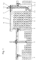
- FIG. 1 shows a cross section through an empty container storage module according to the invention 1 with adjacent container storage modules 2 shown.
- the empty container storage module 1 operates a stacker crane 3, which moves on the elevated crane runways 4, the empty container warehouse 5.
- the stacker crane 3 consists of the portal-like bridge 6 and cat 7.
- the main components of the cat are the three-legged mast 7.1, the double-rope hoist 7.2, the spreader carriage 7.3 and the floating spreader 7.4 in the position of minimum projection.
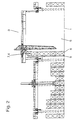
- FIG. 2 likewise shows a section through the container store with integrated empty container store shown in FIG.
- the figure shows the empty container storage module 1 and working therein stacking crane 3 in the construction of the first row Empty container 8 in the empty container store 5.
- a Storage frame 9 which consists of vertically embedded in the ground carriers.
- the Spreader 7.4 is inside the empty container warehouse for this normal stacking activity 5 in the position of minimum projection.
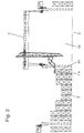
- FIG. 3 shows the empty container storage module 1 and the stacking crane 3 operating therein in a loading area 10 outside the empty container storage 5 at the takeover an empty container 11 from the first row of the adjacent container storage module 2.
- the spreader 7.4 was used for this transhipment activity outside the Empty container storage 5 pivoted in the position of maximum deflection.
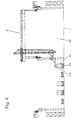
- FIG. 4 shows a further section through a container store with integrated empty container store shown.
- the figure shows the empty container storage module 1 and therein the stacker crane 3 in a loading area 12 outside of the empty container storage at the Takeover of an empty container 13 from a AGV (driverless transport vehicle) 14.
- the spreader 7.4 was outside the empty container warehouse for this transhipment activity 5 pivoted to the position of the maximum projection.
- Figure 5 shows the Spreaderwagen 7.3, consisting from the guide frame 15, the pressure arm 16, the parallel link 17, the Spreader carrier 18 and the floating spreader 7.4. Both lifting cylinders 19 determine the minimum end position of the spreader.
- the spreader carriage moves for positioning in vertical direction along the Dreigurtmast 7.1.
- Figure 6 shows the Spreaderwagen 7.3 in its maximum projection.
- the lifting cylinders 19 are fully extended, whereby the parallel link 17 and the pressure arm 16 in the Swivel the drawing to the left and thus move the spreader bar into position moving away from the three-legged mast.
- Figure 7 shows the Dreigurtmast 7.1, the Doppelseilhubwerk 7.2 and Spreaderwagen 7.3 in cross section.
- the four rollers 21 on two double-T-beams 22nd Guided Spreaderwagen is suspended from the two hoisting ropes 20 and by means of a Hoist not shown on the three-mast not shown vertically movable.
- the cat moves 7 with the arranged thereon Dreigurtmast 7.1, for example, in the illustrated in Figure 3 Position, wherein the spreader 7.4 in its largest projection by the elevated Craneway passes through.
- the spreader picks up an empty container 11 and moves it through an alley formed between the crane runways into the area of the empty container storage 5.
- a first row 8 of empty containers stacked by the storage rack. 9 is supported.
- Figure 1 further rows are formed ( Figure 1), wherein the Spreader 7.4 is positioned in the position according to the projection.
- the empty containers may be lifted or unlocked from an AGV this are placed, as shown schematically in Figure 4. It makes sense to sort in the warehouse according to container types, ie after Sizes (20 ', 30', 40 ', 45', 48 '50'), by height (4 ', 4'6 ", 8', 8'6", 9 ', 9'6 “and 9'61 ⁇ 2 ") Execution (standard container, top-top container, tank container, bulk container and Flads), as well as after owners (various shipping companies).
- the container storage according to the invention works fully automatically after a set program and settles in the expiration of an automatic container terminal integrate.
Description
- Figur 1
- ein Schnitt durch ein Containerlager mit integriertem Leercontainerlager,
- Figur 2
- das Containerlager nach Figur 1 beim Aufbau der ersten Leercontainerreihe,
- Figur 3
- einen weiteren Schnitt durch das Containerlager nach Figur 1,
- Figur 4
- das Leercontainer-Lagermodul,
- Figur 5
- eine Detailansicht des Spreaderträgers in der Position mit minimaler Ausladung,
- Figur 6
- eine Detailansicht des Spreaderträgers in der Position mit maximaler Ausladung, und
- Figur 7
- einen Schnitt durch den Dreigurtmast oberhalb des Spreaderwagens.
Claims (6)
- Leercontainerlager zum Zwischenlagern von ISO-Leercontainern, insbesondere in vollautomatischen Seehafen- oder Binnenhafen-Containerterminals, mit einem automatisierbaren, das Leercontainerlager (1) überspannenden, auf einer aufgeständerten Kranbahn (4) verfahrbaren Brückenportalkran (6) mit einer darauf in dessen Längsrichtung verfahrbaren Laufkatze (7), an der eine vertikale Hubsäule (7.1) für ein heb- und senkbares Lastaufnahmemittel (7.3,7.4) für den Leercontainer (8,11,13) befestigt ist, wobei das Lastaufnahmemittel ein Spreader (7.4) ist, der an einem mittels Rollen (21) an der Hubsäule (7.1) geführten Spreaderwagen (7.3) an einem Spreaderträger (18) angeordnet ist,
dadurch gekennzeichnet, dass der Spreaderträger (18) mit dem Spreader (7.3) in der vertikalen Längsmittelebene des Spreaderwagens (7.3) aus einer der Hubsäule (7.1) nahen in eine der Hubsäule (7.1) feme Position verschwenkbar ist. - Leercontainerlager nach Anspruch 1,
dadurch gekennzeichnet, dass die vertikale Hubsäule (7.1) aus einer Gittermaststruktur mit vorzugsweise drei Gurten gebildet ist, an dem das Lastaufnahmemittel (7.3, 7.4) vertikal verfahrbar geführt ist. - Leercontainerlager nach Anspruch 1 oder 2,
dadurch gekennzeichnet, dass zum vertikalen Verfahren des Spreaderwagens (7.3) ein Doppelseilhubwerk (7.2) mit an der Hubsäule (7.1) vorgesehenen Umlenkrollen vorgesehen ist. - Leercontainerlager nach einem der Ansprüche 1 bis 3,
dadurch gekennzeichnet, dass der Spreaderträger (18) mit dem Spreaderwagen (7.3) über Parallellenker (17) verbunden ist, die mittels mindestens einer Kolben-Zylindereinheit (19) verschwenkbar sind. - Leercontainerlager nach einem der Ansprüche 1 bis 4,
dadurch gekennzeichnet, dass der Spreaderträger (18) zusammen mit dem Spreader (7.3) in seiner der Hubsäule (7.1) fernen Schwenkposition derartig weit ausschwenkbar ist, dass bei einer der Kranbahnschiene nahen Stellung der Hubsäule (7.1) der Spreader (7.4) die Ständer der Kranbahn (4) durchgreift. - Leercontainerlager nach einem der Ansprüche 1 bis 5,
dadurch gekennzeichnet, dass zur Stabilisierung mindestens der ersten Containerstapelreihe (8) in dem der Kranbahn (4) nahen Bereich ein Lagergerüst (9) vorgesehen ist, das aus vertikalen Säulen oder Trägern besteht, deren Höhe der Höhe der maximal aufstapelbaren Container (13) entspricht und deren horizontaler Abstand kleiner als die Längserstreckung des kürzesten zu stapelnden Containers (13) ist, wobei mindestens eine Gasse zwischen zwei Säulen oder Trägem gebildet wird, durch die auch der längste Container (13) in seiner Querrichtung austragbar ist.
Priority Applications (1)
| Application Number | Priority Date | Filing Date | Title |
|---|---|---|---|
| DK01909526T DK1365984T3 (da) | 2000-02-23 | 2001-01-23 | Lager til tomme containere for mellemlagring af tomme ISO-containere |
Applications Claiming Priority (3)
| Application Number | Priority Date | Filing Date | Title |
|---|---|---|---|
| DE10009737 | 2000-02-23 | ||
| DE10009737 | 2000-02-23 | ||
| PCT/DE2001/000317 WO2001062656A2 (de) | 2000-02-23 | 2001-01-23 | Leercontainerlager zum zwischenlagern von iso-leercontainern |
Publications (2)
| Publication Number | Publication Date |
|---|---|
| EP1365984A2 EP1365984A2 (de) | 2003-12-03 |
| EP1365984B1 true EP1365984B1 (de) | 2005-03-16 |
Family
ID=7632950
Family Applications (1)
| Application Number | Title | Priority Date | Filing Date |
|---|---|---|---|
| EP01909526A Expired - Lifetime EP1365984B1 (de) | 2000-02-23 | 2001-01-23 | Leercontainerlager zum zwischenlagern von iso-leercontainern |
Country Status (10)
| Country | Link |
|---|---|
| US (1) | US7004338B2 (de) |
| EP (1) | EP1365984B1 (de) |
| JP (1) | JP4184665B2 (de) |
| KR (1) | KR100694689B1 (de) |
| AT (1) | ATE290991T1 (de) |
| AU (1) | AU2001237238A1 (de) |
| DE (1) | DE50105656D1 (de) |
| ES (1) | ES2237555T3 (de) |
| PT (1) | PT1365984E (de) |
| WO (1) | WO2001062656A2 (de) |
Cited By (4)
| Publication number | Priority date | Publication date | Assignee | Title |
|---|---|---|---|---|
| DE102008046154A1 (de) | 2008-09-06 | 2010-03-18 | Gottwald Port Technology Gmbh | Brücken- oder Portalkran, insbesondere zum Handhaben von ISO-Containern |
| DE102008061198A1 (de) | 2008-12-09 | 2010-06-10 | Gottwald Port Technology Gmbh | Verfahren und eine Anlage zum Umschlag von normierten Ladungssträgern, insbesondere ISO-Containern und Wechselaufbauten, zwischen Schiene und Straße |
| DE102008061197A1 (de) | 2008-12-09 | 2010-06-24 | Gottwald Port Technology Gmbh | Brücken- oder Portalkran für den Umschlag von normierten Ladungsträgern |
| DE102008061199B3 (de) * | 2008-12-09 | 2010-08-05 | Gottwald Port Technology Gmbh | Brücken- oder Portalkran für den Umschlag von normierten Ladungsträgern, insbesondere für den Umschlag von ISO-Containern im Hafenbereich |
Families Citing this family (8)
| Publication number | Priority date | Publication date | Assignee | Title |
|---|---|---|---|---|
| EP2266080A1 (de) * | 2008-03-30 | 2010-12-29 | Flavio Costa | Logistiksystem für ökologische waren |
| NL2009502C2 (nl) * | 2012-07-18 | 2014-01-23 | Raadgevend Ingenieursburo F Koch B V | Bovenloopkraan en samenstel van ten minste twee bovenloopkranen. |
| JP2015529181A (ja) * | 2012-09-21 | 2015-10-05 | シーダブリューティー リミテッド | 貨物コンテナの格納及び取り出しシステム、並びにこれを実施する方法 |
| FI125422B (fi) * | 2013-12-12 | 2015-10-15 | Konecranes Oyj | Järjestely kuormauselimen heilahduksen vaimentamiseksi nosturissa |
| GB201503159D0 (en) * | 2015-02-25 | 2015-04-08 | Fosbel Inc | Methods and apparatus for constructing glass furnace structures |
| ITUA20163616A1 (it) * | 2016-05-19 | 2017-11-19 | Roberto Gentili | "gru a cavalletto scorrevole su rotaie con dispositivo di sollevamento a bracci telescopici oscillanti" |
| NO344464B1 (en) | 2017-10-19 | 2019-12-23 | Autostore Tech As | Vehicle for an automated storage and retrieval system and method of operating an automated storage and retrieval system |
| DE102022117327A1 (de) * | 2022-07-12 | 2024-01-18 | Amova Gmbh | Hochregallager für Leercontainer |
Family Cites Families (10)
| Publication number | Priority date | Publication date | Assignee | Title |
|---|---|---|---|---|
| DE1556636A1 (de) * | 1968-02-22 | 1970-10-22 | Krupp Gmbh | Container-Umschlaganlage |
| US3543952A (en) * | 1968-03-29 | 1970-12-01 | Kaiser Ind Corp | Container handling and storage system |
| US3741409A (en) * | 1971-12-01 | 1973-06-26 | Freeport Brick Co | Transfer apparatus for articles with a vertical passage |
| JPS5211826B2 (de) * | 1972-10-18 | 1977-04-02 | ||
| JPS5874490A (ja) * | 1981-10-27 | 1983-05-04 | 川崎製鉄株式会社 | スラブ掴みリフタ−を具備した天井クレ−ンによるスラブのハンドリング方法 |
| US4610594A (en) * | 1985-01-07 | 1986-09-09 | Dominion Chain Inc. | Container conveyor system |
| US5718550A (en) * | 1992-04-16 | 1998-02-17 | Mi-Jack Products, Inc. | Load transferring system |
| DE4342522A1 (de) * | 1993-09-01 | 1995-06-22 | Krupp Foerdertechnik Gmbh | Umschlaggerät für Großbehälter |
| JPH09255112A (ja) * | 1996-03-26 | 1997-09-30 | Ishikawajima Harima Heavy Ind Co Ltd | 自走式スプレッダのツイストロック装置 |
| DE19700469A1 (de) * | 1997-01-09 | 1998-07-16 | Krupp Foerdertechnik Gmbh | Einrichtung für das Ent- und Beladen von Schiffen |
-
2001
- 2001-01-23 US US10/204,296 patent/US7004338B2/en not_active Expired - Fee Related
- 2001-01-23 KR KR1020027010859A patent/KR100694689B1/ko not_active IP Right Cessation
- 2001-01-23 AU AU2001237238A patent/AU2001237238A1/en not_active Abandoned
- 2001-01-23 DE DE50105656T patent/DE50105656D1/de not_active Expired - Lifetime
- 2001-01-23 EP EP01909526A patent/EP1365984B1/de not_active Expired - Lifetime
- 2001-01-23 PT PT01909526T patent/PT1365984E/pt unknown
- 2001-01-23 JP JP2001561673A patent/JP4184665B2/ja not_active Expired - Fee Related
- 2001-01-23 AT AT01909526T patent/ATE290991T1/de active
- 2001-01-23 WO PCT/DE2001/000317 patent/WO2001062656A2/de active IP Right Grant
- 2001-01-23 ES ES01909526T patent/ES2237555T3/es not_active Expired - Lifetime
Cited By (8)
| Publication number | Priority date | Publication date | Assignee | Title |
|---|---|---|---|---|
| DE102008046154A1 (de) | 2008-09-06 | 2010-03-18 | Gottwald Port Technology Gmbh | Brücken- oder Portalkran, insbesondere zum Handhaben von ISO-Containern |
| US8517192B2 (en) | 2008-09-06 | 2013-08-27 | Gottwald Port Technology Gmbh | Dual mast arrangement for a crane |
| DE102008061198A1 (de) | 2008-12-09 | 2010-06-10 | Gottwald Port Technology Gmbh | Verfahren und eine Anlage zum Umschlag von normierten Ladungssträgern, insbesondere ISO-Containern und Wechselaufbauten, zwischen Schiene und Straße |
| WO2010066602A1 (de) | 2008-12-09 | 2010-06-17 | Gottwald Port Technology Gmbh | Verfahren und eine anlage zum umschlag von normierten ladungsträgern, insbesondere iso-containern und wechselaufbauten, zwischen schiene und strasse |
| DE102008061197A1 (de) | 2008-12-09 | 2010-06-24 | Gottwald Port Technology Gmbh | Brücken- oder Portalkran für den Umschlag von normierten Ladungsträgern |
| DE102008061197B4 (de) * | 2008-12-09 | 2010-08-05 | Gottwald Port Technology Gmbh | Brücken- oder Portalkran für den Umschlag von normierten Ladungsträgern |
| DE102008061199B3 (de) * | 2008-12-09 | 2010-08-05 | Gottwald Port Technology Gmbh | Brücken- oder Portalkran für den Umschlag von normierten Ladungsträgern, insbesondere für den Umschlag von ISO-Containern im Hafenbereich |
| US8800791B2 (en) | 2008-12-09 | 2014-08-12 | Gottwald Port Technology Gmbh | Bridge crane or gantry crane comprising a revolving arrangement and lifting frames suspended thereunder |
Also Published As
| Publication number | Publication date |
|---|---|
| DE50105656D1 (de) | 2005-04-21 |
| JP2004500296A (ja) | 2004-01-08 |
| WO2001062656A2 (de) | 2001-08-30 |
| ATE290991T1 (de) | 2005-04-15 |
| US20030077154A1 (en) | 2003-04-24 |
| AU2001237238A1 (en) | 2001-09-03 |
| WO2001062656A3 (de) | 2003-09-12 |
| US7004338B2 (en) | 2006-02-28 |
| JP4184665B2 (ja) | 2008-11-19 |
| KR100694689B1 (ko) | 2007-03-13 |
| EP1365984A2 (de) | 2003-12-03 |
| ES2237555T3 (es) | 2005-08-01 |
| PT1365984E (pt) | 2005-07-29 |
| KR20020075443A (ko) | 2002-10-04 |
Similar Documents
| Publication | Publication Date | Title |
|---|---|---|
| DE1915737C3 (de) | Regalförderzeug für Frachtcontainer | |
| EP3429947B1 (de) | System aus einem regalbediengerät und einem transport- und übergabesystem zum ein- und auslagern oder umlagern von standardcontainern | |
| EP1519890B1 (de) | Umschlaganlage und verfahren zum be- und entladen von containern aus containerschiffen | |
| EP2496510B1 (de) | Umschlagsystem für iso-container mit einer containerbrücke | |
| DE2539968A1 (de) | Verladevorrichtung, insbesondere fuer container | |
| EP2683629A1 (de) | Zirkulares roaming | |
| EP2321213B1 (de) | Brücken- oder portalkran, insbesondere zum handhaben von iso-containern | |
| EP1365984B1 (de) | Leercontainerlager zum zwischenlagern von iso-leercontainern | |
| EP3097044B1 (de) | Stapelkran mit containerzwischenlagerplatz | |
| AT506918B1 (de) | Aufnahmevorrichtung für ein förderfahrzeug | |
| DE2641027A1 (de) | Kran zum verladen von umschlagguetern einheitlicher abmessungen | |
| DE10307579A1 (de) | Umschlaganlage in einem See- oder Binnenhafen | |
| DE19958501A1 (de) | Hubeinrichtung zur Erhöhung der Leistung eines Umschlaggerätes für ISO-Container | |
| DE1222857B (de) | Stapelkrananlage fuer Langgut | |
| WO1994001357A1 (de) | Einrichtung zum be- und/oder entladen von stückgut | |
| DE2513541A1 (de) | Teleskoplagerkran, insbesondere fuer schiffsladeraeume | |
| DE19740814A1 (de) | Containerbrückensystem | |
| DE60213472T2 (de) | Verfahren zum pufferkranbetrieb bei der handhabung von frachtbehältern | |
| DE4002289A1 (de) | Einrichtung zum heben und transportieren schwerer gegenstaende | |
| DE102015115323A1 (de) | Regalbediengerät | |
| EP0339015B1 (de) | Krananlage mit einbahnigem Fördersystem für den Stückguttransport | |
| DE3435690A1 (de) | Portalfahrzeug | |
| EP0436507A1 (de) | Vorrichtung zum Fördern von Paletten | |
| EP2885218B1 (de) | Lagervorrichtung zum lagern einer containereinheit, system und anlage zum lagern von containereinheiten | |
| DD234259A5 (de) | Portalkrananlage |
Legal Events
| Date | Code | Title | Description |
|---|---|---|---|
| PUAI | Public reference made under article 153(3) epc to a published international application that has entered the european phase |
Free format text: ORIGINAL CODE: 0009012 |
|
| 17P | Request for examination filed |
Effective date: 20020819 |
|
| AK | Designated contracting states |
Kind code of ref document: A2 Designated state(s): AT BE CH CY DE DK ES FI FR GB GR IE IT LI LU MC NL PT SE TR |
|
| RAP1 | Party data changed (applicant data changed or rights of an application transferred) |
Owner name: GOTTWALD PORT TECHNOLOGY GMBH |
|
| 17Q | First examination report despatched |
Effective date: 20040302 |
|
| GRAP | Despatch of communication of intention to grant a patent |
Free format text: ORIGINAL CODE: EPIDOSNIGR1 |
|
| GRAS | Grant fee paid |
Free format text: ORIGINAL CODE: EPIDOSNIGR3 |
|
| GRAA | (expected) grant |
Free format text: ORIGINAL CODE: 0009210 |
|
| AK | Designated contracting states |
Kind code of ref document: B1 Designated state(s): AT BE CH CY DE DK ES FI FR GB GR IE IT LI LU MC NL PT SE TR |
|
| REG | Reference to a national code |
Ref country code: GB Ref legal event code: FG4D Free format text: NOT ENGLISH |
|
| REG | Reference to a national code |
Ref country code: CH Ref legal event code: EP |
|
| REG | Reference to a national code |
Ref country code: SE Ref legal event code: TRGR |
|
| REG | Reference to a national code |
Ref country code: IE Ref legal event code: FG4D Free format text: GERMAN |
|
| REF | Corresponds to: |
Ref document number: 50105656 Country of ref document: DE Date of ref document: 20050421 Kind code of ref document: P |
|
| GBT | Gb: translation of ep patent filed (gb section 77(6)(a)/1977) |
Effective date: 20050523 |
|
| REG | Reference to a national code |
Ref country code: DK Ref legal event code: T3 |
|
| REG | Reference to a national code |
Ref country code: GR Ref legal event code: EP Ref document number: 20050401886 Country of ref document: GR |
|
| REG | Reference to a national code |
Ref country code: PT Ref legal event code: SC4A Effective date: 20050527 |
|
| REG | Reference to a national code |
Ref country code: ES Ref legal event code: FG2A Ref document number: 2237555 Country of ref document: ES Kind code of ref document: T3 |
|
| ET | Fr: translation filed | ||
| PLBE | No opposition filed within time limit |
Free format text: ORIGINAL CODE: 0009261 |
|
| STAA | Information on the status of an ep patent application or granted ep patent |
Free format text: STATUS: NO OPPOSITION FILED WITHIN TIME LIMIT |
|
| PG25 | Lapsed in a contracting state [announced via postgrant information from national office to epo] |
Ref country code: MC Free format text: LAPSE BECAUSE OF NON-PAYMENT OF DUE FEES Effective date: 20060131 Ref country code: CH Free format text: LAPSE BECAUSE OF NON-PAYMENT OF DUE FEES Effective date: 20060131 Ref country code: LI Free format text: LAPSE BECAUSE OF NON-PAYMENT OF DUE FEES Effective date: 20060131 |
|
| 26N | No opposition filed |
Effective date: 20051219 |
|
| REG | Reference to a national code |
Ref country code: CH Ref legal event code: PL |
|
| PG25 | Lapsed in a contracting state [announced via postgrant information from national office to epo] |
Ref country code: TR Free format text: LAPSE BECAUSE OF FAILURE TO SUBMIT A TRANSLATION OF THE DESCRIPTION OR TO PAY THE FEE WITHIN THE PRESCRIBED TIME-LIMIT Effective date: 20050316 |
|
| PG25 | Lapsed in a contracting state [announced via postgrant information from national office to epo] |
Ref country code: CY Free format text: LAPSE BECAUSE OF FAILURE TO SUBMIT A TRANSLATION OF THE DESCRIPTION OR TO PAY THE FEE WITHIN THE PRESCRIBED TIME-LIMIT Effective date: 20050316 |
|
| PGFP | Annual fee paid to national office [announced via postgrant information from national office to epo] |
Ref country code: LU Payment date: 20140123 Year of fee payment: 14 |
|
| PGFP | Annual fee paid to national office [announced via postgrant information from national office to epo] |
Ref country code: SE Payment date: 20140121 Year of fee payment: 14 Ref country code: DK Payment date: 20140121 Year of fee payment: 14 Ref country code: FI Payment date: 20140113 Year of fee payment: 14 Ref country code: DE Payment date: 20140122 Year of fee payment: 14 Ref country code: NL Payment date: 20140121 Year of fee payment: 14 Ref country code: IE Payment date: 20140128 Year of fee payment: 14 Ref country code: BE Payment date: 20140121 Year of fee payment: 14 |
|
| PGFP | Annual fee paid to national office [announced via postgrant information from national office to epo] |
Ref country code: AT Payment date: 20140113 Year of fee payment: 14 Ref country code: IT Payment date: 20140129 Year of fee payment: 14 Ref country code: GR Payment date: 20140121 Year of fee payment: 14 Ref country code: ES Payment date: 20140129 Year of fee payment: 14 Ref country code: FR Payment date: 20140123 Year of fee payment: 14 |
|
| PGFP | Annual fee paid to national office [announced via postgrant information from national office to epo] |
Ref country code: GB Payment date: 20140121 Year of fee payment: 14 Ref country code: PT Payment date: 20140120 Year of fee payment: 14 |
|
| PG25 | Lapsed in a contracting state [announced via postgrant information from national office to epo] |
Ref country code: BE Free format text: LAPSE BECAUSE OF NON-PAYMENT OF DUE FEES Effective date: 20150131 |
|
| REG | Reference to a national code |
Ref country code: PT Ref legal event code: MM4A Free format text: LAPSE DUE TO NON-PAYMENT OF FEES Effective date: 20150723 |
|
| REG | Reference to a national code |
Ref country code: DE Ref legal event code: R119 Ref document number: 50105656 Country of ref document: DE |
|
| REG | Reference to a national code |
Ref country code: NL Ref legal event code: V1 Effective date: 20150801 |
|
| PG25 | Lapsed in a contracting state [announced via postgrant information from national office to epo] |
Ref country code: LU Free format text: LAPSE BECAUSE OF NON-PAYMENT OF DUE FEES Effective date: 20150123 |
|
| REG | Reference to a national code |
Ref country code: DK Ref legal event code: EBP Effective date: 20150131 |
|
| REG | Reference to a national code |
Ref country code: SE Ref legal event code: EUG |
|
| REG | Reference to a national code |
Ref country code: AT Ref legal event code: MM01 Ref document number: 290991 Country of ref document: AT Kind code of ref document: T Effective date: 20150123 |
|
| GBPC | Gb: european patent ceased through non-payment of renewal fee |
Effective date: 20150123 |
|
| PG25 | Lapsed in a contracting state [announced via postgrant information from national office to epo] |
Ref country code: NL Free format text: LAPSE BECAUSE OF NON-PAYMENT OF DUE FEES Effective date: 20150801 |
|
| REG | Reference to a national code |
Ref country code: GR Ref legal event code: ML Ref document number: 20050401886 Country of ref document: GR Effective date: 20150805 |
|
| PG25 | Lapsed in a contracting state [announced via postgrant information from national office to epo] |
Ref country code: DE Free format text: LAPSE BECAUSE OF NON-PAYMENT OF DUE FEES Effective date: 20150801 Ref country code: GB Free format text: LAPSE BECAUSE OF NON-PAYMENT OF DUE FEES Effective date: 20150123 Ref country code: FI Free format text: LAPSE BECAUSE OF NON-PAYMENT OF DUE FEES Effective date: 20150123 Ref country code: PT Free format text: LAPSE BECAUSE OF NON-PAYMENT OF DUE FEES Effective date: 20150723 |
|
| REG | Reference to a national code |
Ref country code: FR Ref legal event code: ST Effective date: 20150930 |
|
| REG | Reference to a national code |
Ref country code: IE Ref legal event code: MM4A |
|
| PG25 | Lapsed in a contracting state [announced via postgrant information from national office to epo] |
Ref country code: SE Free format text: LAPSE BECAUSE OF NON-PAYMENT OF DUE FEES Effective date: 20150124 Ref country code: AT Free format text: LAPSE BECAUSE OF NON-PAYMENT OF DUE FEES Effective date: 20150123 Ref country code: FR Free format text: LAPSE BECAUSE OF NON-PAYMENT OF DUE FEES Effective date: 20150202 Ref country code: GR Free format text: LAPSE BECAUSE OF NON-PAYMENT OF DUE FEES Effective date: 20150805 |
|
| PG25 | Lapsed in a contracting state [announced via postgrant information from national office to epo] |
Ref country code: IT Free format text: LAPSE BECAUSE OF NON-PAYMENT OF DUE FEES Effective date: 20150123 |
|
| PG25 | Lapsed in a contracting state [announced via postgrant information from national office to epo] |
Ref country code: DK Free format text: LAPSE BECAUSE OF NON-PAYMENT OF DUE FEES Effective date: 20150131 Ref country code: IE Free format text: LAPSE BECAUSE OF NON-PAYMENT OF DUE FEES Effective date: 20150123 |
|
| REG | Reference to a national code |
Ref country code: ES Ref legal event code: FD2A Effective date: 20160226 |
|
| PG25 | Lapsed in a contracting state [announced via postgrant information from national office to epo] |
Ref country code: ES Free format text: LAPSE BECAUSE OF NON-PAYMENT OF DUE FEES Effective date: 20150124 |