EP1361104B1 - Mechanismus für höhenverstellbaren Sitz und Lenkrad, insbesondere für gepanzertes Fahrzeug - Google Patents
Mechanismus für höhenverstellbaren Sitz und Lenkrad, insbesondere für gepanzertes Fahrzeug Download PDFInfo
- Publication number
- EP1361104B1 EP1361104B1 EP03396039A EP03396039A EP1361104B1 EP 1361104 B1 EP1361104 B1 EP 1361104B1 EP 03396039 A EP03396039 A EP 03396039A EP 03396039 A EP03396039 A EP 03396039A EP 1361104 B1 EP1361104 B1 EP 1361104B1
- Authority
- EP
- European Patent Office
- Prior art keywords
- seat
- steering wheel
- frame
- vehicle
- seat frame
- Prior art date
- Legal status (The legal status is an assumption and is not a legal conclusion. Google has not performed a legal analysis and makes no representation as to the accuracy of the status listed.)
- Expired - Lifetime
Links
- 230000002349 favourable effect Effects 0.000 claims description 3
- 230000001133 acceleration Effects 0.000 description 2
- 230000007613 environmental effect Effects 0.000 description 1
- 210000003128 head Anatomy 0.000 description 1
- 230000001771 impaired effect Effects 0.000 description 1
Images


Classifications
-
- B—PERFORMING OPERATIONS; TRANSPORTING
- B60—VEHICLES IN GENERAL
- B60N—SEATS SPECIALLY ADAPTED FOR VEHICLES; VEHICLE PASSENGER ACCOMMODATION NOT OTHERWISE PROVIDED FOR
- B60N2/00—Seats specially adapted for vehicles; Arrangement or mounting of seats in vehicles
- B60N2/24—Seats specially adapted for vehicles; Arrangement or mounting of seats in vehicles for particular purposes or particular vehicles
- B60N2/42—Seats specially adapted for vehicles; Arrangement or mounting of seats in vehicles for particular purposes or particular vehicles the seat constructed to protect the occupant from the effect of abnormal g-forces, e.g. crash or safety seats
- B60N2/4207—Seats specially adapted for vehicles; Arrangement or mounting of seats in vehicles for particular purposes or particular vehicles the seat constructed to protect the occupant from the effect of abnormal g-forces, e.g. crash or safety seats characterised by the direction of the g-forces
- B60N2/4242—Seats specially adapted for vehicles; Arrangement or mounting of seats in vehicles for particular purposes or particular vehicles the seat constructed to protect the occupant from the effect of abnormal g-forces, e.g. crash or safety seats characterised by the direction of the g-forces vertical
-
- B—PERFORMING OPERATIONS; TRANSPORTING
- B60—VEHICLES IN GENERAL
- B60N—SEATS SPECIALLY ADAPTED FOR VEHICLES; VEHICLE PASSENGER ACCOMMODATION NOT OTHERWISE PROVIDED FOR
- B60N2/00—Seats specially adapted for vehicles; Arrangement or mounting of seats in vehicles
- B60N2/02—Seats specially adapted for vehicles; Arrangement or mounting of seats in vehicles the seat or part thereof being movable, e.g. adjustable
- B60N2/04—Seats specially adapted for vehicles; Arrangement or mounting of seats in vehicles the seat or part thereof being movable, e.g. adjustable the whole seat being movable
- B60N2/06—Seats specially adapted for vehicles; Arrangement or mounting of seats in vehicles the seat or part thereof being movable, e.g. adjustable the whole seat being movable slidable
-
- B—PERFORMING OPERATIONS; TRANSPORTING
- B60—VEHICLES IN GENERAL
- B60N—SEATS SPECIALLY ADAPTED FOR VEHICLES; VEHICLE PASSENGER ACCOMMODATION NOT OTHERWISE PROVIDED FOR
- B60N2/00—Seats specially adapted for vehicles; Arrangement or mounting of seats in vehicles
- B60N2/02—Seats specially adapted for vehicles; Arrangement or mounting of seats in vehicles the seat or part thereof being movable, e.g. adjustable
- B60N2/04—Seats specially adapted for vehicles; Arrangement or mounting of seats in vehicles the seat or part thereof being movable, e.g. adjustable the whole seat being movable
- B60N2/16—Seats specially adapted for vehicles; Arrangement or mounting of seats in vehicles the seat or part thereof being movable, e.g. adjustable the whole seat being movable height-adjustable
- B60N2/1605—Seats specially adapted for vehicles; Arrangement or mounting of seats in vehicles the seat or part thereof being movable, e.g. adjustable the whole seat being movable height-adjustable characterised by the cinematic
- B60N2/161—Rods
-
- B—PERFORMING OPERATIONS; TRANSPORTING
- B60—VEHICLES IN GENERAL
- B60N—SEATS SPECIALLY ADAPTED FOR VEHICLES; VEHICLE PASSENGER ACCOMMODATION NOT OTHERWISE PROVIDED FOR
- B60N2/00—Seats specially adapted for vehicles; Arrangement or mounting of seats in vehicles
- B60N2/02—Seats specially adapted for vehicles; Arrangement or mounting of seats in vehicles the seat or part thereof being movable, e.g. adjustable
- B60N2/04—Seats specially adapted for vehicles; Arrangement or mounting of seats in vehicles the seat or part thereof being movable, e.g. adjustable the whole seat being movable
- B60N2/16—Seats specially adapted for vehicles; Arrangement or mounting of seats in vehicles the seat or part thereof being movable, e.g. adjustable the whole seat being movable height-adjustable
- B60N2/1635—Seats specially adapted for vehicles; Arrangement or mounting of seats in vehicles the seat or part thereof being movable, e.g. adjustable the whole seat being movable height-adjustable characterised by the drive mechanism
- B60N2/164—Linear actuator, e.g. screw mechanism
-
- B—PERFORMING OPERATIONS; TRANSPORTING
- B60—VEHICLES IN GENERAL
- B60N—SEATS SPECIALLY ADAPTED FOR VEHICLES; VEHICLE PASSENGER ACCOMMODATION NOT OTHERWISE PROVIDED FOR
- B60N2/00—Seats specially adapted for vehicles; Arrangement or mounting of seats in vehicles
- B60N2/02—Seats specially adapted for vehicles; Arrangement or mounting of seats in vehicles the seat or part thereof being movable, e.g. adjustable
- B60N2/04—Seats specially adapted for vehicles; Arrangement or mounting of seats in vehicles the seat or part thereof being movable, e.g. adjustable the whole seat being movable
- B60N2/16—Seats specially adapted for vehicles; Arrangement or mounting of seats in vehicles the seat or part thereof being movable, e.g. adjustable the whole seat being movable height-adjustable
- B60N2/1635—Seats specially adapted for vehicles; Arrangement or mounting of seats in vehicles the seat or part thereof being movable, e.g. adjustable the whole seat being movable height-adjustable characterised by the drive mechanism
- B60N2/1665—Hydraulic or pneumatic actuation
-
- B—PERFORMING OPERATIONS; TRANSPORTING
- B60—VEHICLES IN GENERAL
- B60N—SEATS SPECIALLY ADAPTED FOR VEHICLES; VEHICLE PASSENGER ACCOMMODATION NOT OTHERWISE PROVIDED FOR
- B60N2/00—Seats specially adapted for vehicles; Arrangement or mounting of seats in vehicles
- B60N2/24—Seats specially adapted for vehicles; Arrangement or mounting of seats in vehicles for particular purposes or particular vehicles
- B60N2/38—Seats specially adapted for vehicles; Arrangement or mounting of seats in vehicles for particular purposes or particular vehicles specially constructed for use on tractors or like off-road vehicles
-
- B—PERFORMING OPERATIONS; TRANSPORTING
- B62—LAND VEHICLES FOR TRAVELLING OTHERWISE THAN ON RAILS
- B62D—MOTOR VEHICLES; TRAILERS
- B62D1/00—Steering controls, i.e. means for initiating a change of direction of the vehicle
- B62D1/02—Steering controls, i.e. means for initiating a change of direction of the vehicle vehicle-mounted
- B62D1/16—Steering columns
- B62D1/18—Steering columns yieldable or adjustable, e.g. tiltable
-
- F—MECHANICAL ENGINEERING; LIGHTING; HEATING; WEAPONS; BLASTING
- F41—WEAPONS
- F41H—ARMOUR; ARMOURED TURRETS; ARMOURED OR ARMED VEHICLES; MEANS OF ATTACK OR DEFENCE, e.g. CAMOUFLAGE, IN GENERAL
- F41H7/00—Armoured or armed vehicles
- F41H7/02—Land vehicles with enclosing armour, e.g. tanks
-
- F—MECHANICAL ENGINEERING; LIGHTING; HEATING; WEAPONS; BLASTING
- F41—WEAPONS
- F41H—ARMOUR; ARMOURED TURRETS; ARMOURED OR ARMED VEHICLES; MEANS OF ATTACK OR DEFENCE, e.g. CAMOUFLAGE, IN GENERAL
- F41H7/00—Armoured or armed vehicles
- F41H7/02—Land vehicles with enclosing armour, e.g. tanks
- F41H7/04—Armour construction
- F41H7/046—Shock resilient mounted seats for armoured or fighting vehicles
Definitions
- the present invention relates to a vehicle as defined in the preamble of claim 1.
- specifications DE-A-1 630 402 and DE-A-2307183 disclose an armored vehicle comprising a body within which a driver's seat is provided in a control cabin.
- the control cabin is delimited in an upward and/or forward direction by a wall.
- the top of the vehicle is provided with an opening, which is aligned with the driver's seat.
- the vehicle has an openable and closeable hatch arranged to cover the opening.
- the opening usually functions as a manhole through which the driver can get into and out of the control cabin.
- the opening is provided with viewing means allowing the driver to see outside to permit the vehicle to be steered.
- the viewing means may comprise a porthole in the front edge of the hatch and/or a periscope arranged in it.
- the seat is supported on a seat frame, which is pivotally mounted at one end on a wall so that it can turn about a horizontal pivot shaft transverse relative to the vehicle between a low position and a high position. In the high position of the seat frame, the seat is closer to the opening than in the low position.
- the seat frame can be turned by means of an actuator about said pivot shaft to adjust the height position of the seat. The driver can adjust the seat height so that the position of the driver's eyes relative to the opening and/or to the viewing means provided in the hatch will be suitable.
- the vehicle is driven with the seat in one of two different positions of adjustment such that, either the level of the driver's eyes is above the edge of the opening, or alternatively the level of the driver's eyes is below the edge of the opening, in which case a periscope is used for the viewing.
- the seat frame is mounted on a wall instead of the floor is an advantageous solution as it improves the driver's safety in situations where the vehicle body undergoes accelerations, for example when the vehicle is moving on uneven terrain, bumps into an obstacle or drives onto a mine or when the vehicle is hit by a missile.
- accelerations will not be transmitted from the floor structures directly to the driver.
- a steering wheel is provided in front of and near the seat, the steering wheel being connected to a console which is fastened to said seat frame.
- the prior-art solutions have the drawback that, the steering wheel being supported on a turnable seat frame, when the height position is adjusted, the steering wheel is turned along with the seat frame through an equal amount, with the result that the driving ergonomics is necessarily impaired when the seat frame is turned to bring the seat from the low position to the high position.
- the object of the invention is to overcome the drawbacks of prior art.
- a specific object of the invention is to disclose a vehicle in which the position of the seat and that of the steering wheel are adjusted simultaneously so as to allow the steering ergonomics, i.e. the distances of the seat and steering wheel, to be maintained within a predetermined scope in different positions of adjustment.
- the vehicle of the invention is characterized by what is disclosed in claim 1.
- the vehicle of the invention comprises a body; a cabin space contained within the body and delimited by a wall in a direction upward and/or forward; a driver's seat placed in the cabin space; an opening provided in a wall above the seat and aligned with the seat; an openable and closeable hatch for the opening, said hatch being provided with viewing means allowing the driver to see outside; a steering wheel placed forward of the seat; a seat frame pivotally mounted on a wall by a first joint so as to be turnable about a horizontal first pivot shaft transverse relative to the vehicle between a low position and a high position, the seat being mounted on the other end of said seat frame, so that in the high position the seat is closer to the opening than in the low position; and an actuator for turning the seat frame about the first pivot shaft to adjust the height position of the seat.
- the vehicle comprises a steering wheel frame, which is supported at one end on the wall by a second joint at a distance from the first joint so that it can turn about a second pivot shaft parallel to the first pivot shaft.
- the steering wheel is mounted at the other end of the steering wheel frame.
- the vehicle comprises a connecting bar fitted between the seat frame and the steering wheel frame to cause the steering wheel frame to move simultaneously with the seat frame to adjust the position of the steering wheel.
- the arrangement of the invention provides the advantage that the mutual positions of the seat and the steering wheel can be caused to be adjusted in a way that allows the steering ergonomics, i.e. the distances between the seat and the steering wheel, to be maintained within a predetermined scope in different positions of adjustment.
- the driver does not have to perform any specific actions to adjust the steering wheel when changing the driving position between the low position and the high position, because the steering wheel frame is adjusted by means of the connecting bar simultaneously with the seat frame in a suitable relationship.
- one end of the connecting bar is pivotally connected to the seat frame by a third joint placed at a distance from the first joint while its second end is pivotally connected to the steering wheel frame by a fourth joint placed at a distance from the second joint so that the first joint, second joint, third joint and fourth joint form the pivots of a four-bar linkage mechanism.
- the leverages of the four-bar linkage mechanism formed by the joints are so fitted that the distance of the steering wheel relative to the seat remains favorable in respect of driving ergonomics when the seat frame is moved between the low position and the high position.
- the vehicle comprises foot pedals and a pedal support on which the pedals are mounted, said pedal support being connected to the seat frame so as to be turnable together with the seat frame.
- the vehicle comprises a footrest to allow the driver to rest his left foot on it, the footrest being mounted on the seat frame so as to be turnable together with the seat frame.
- the steering wheel is tiltably mounted in the steering wheel frame so as to allow adjustment of the tilt of the steering wheel.
- the steering wheel may be so mounted in the steering wheel frame that the position of the steering wheel can be adjusted in the direction of its axis of rotation.
- the seat frame may further comprise a guide bar arrangement longitudinal relative to the vehicle to allow the position of the seat relative to the steering wheel to be adjusted along said guide bars.
- the seat frame comprises an entry step surface placed on the seat frame between the steering wheel and the seat to facilitate passage through the opening into the cabin space.
- the actuator is an extendable/retractable-type power means, which is arranged below the seat frame to exert a force between the vehicle body and the seat frame.
- the vehicle is an armored vehicle.
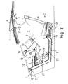
- Fig. 1 shows an armored military vehicle comprising a body 1 with a cabin space 2 within its front part (see figures 2 - 4).
- a driver's seat 4 Provided in the cabin space 2 is a driver's seat 4.
- the vehicle has an opening 5 in its top 3.
- the opening 5 is aligned with the driver's seat.
- the vehicle has an openable and closeable hatch 6 arranged to cover the opening, Fig. 1 showing the hatch in a partially opened position.
- the opening 5 serves as a manhole, through which the driver can get into and out of the cabin space 2.
- Fig. 2 shows the cabin space 2 in side view.
- the driver's seat 4 is connected to the seat frame 9, which is pivotally connected at its forward end to the top wall 3 by a first joint 10 so that the seat frame can turn or "swing" relative to the longitudinal direction of the vehicle about a transverse horizontal first pivot shaft 11 between two extreme positions, a low position I (Fig. 2) and a high position II (Fig. 3 and 4).
- the seat 4 is mounted at the rear end of the seat frame 9.
- the seat frame 9 is in the low position I and the hatch 6 is in a closed position.
- the hatch 6 is kept in the closed position when the vehicle is used in combat or training conditions.
- an extendable/retractable-type power means 12 such as a hydraulic or pneumatic cylinder, screw motor, spindle motor or the like, designed to exert a force between the vehicle body 1 and the seat frame 9, is arranged below the seat frame 9.
- the seat frame 9 is turned about the first pivot shaft 11.
- the steering wheel 8 is connected to the rear end of the steering wheel frame 13.
- the steering wheel frame 13 is supported on the wall 3 at its front end by a second joint 14, which is located at a distance from the first joint 10 so that the steering wheel frame 13 can turn or "swing" about a second pivot shaft 15, said second pivot shaft 15 being mounted horizontally and transversely to the longitudinal direction of the vehicle.
- a connecting bar 16 Arranged between the seat frame 9 and the steering wheel frame 13 is a connecting bar 16 to move the steering wheel frame simultaneously with the seat frame to adjust the position of the steering wheel.
- the connecting bar 18 is pivotally connected at its lower end to the seat frame 9 by a third joint 17, which is disposed at a distance from the first joint 10, and at its upper end pivotally connected to the steering wheel frame 13 by a fourth joint 18, which is disposed at a distance from the second joint 14.
- the first joint 10, second joint 14, third joint 17 and fourth joint 18 form the pivots of a four-bar linkage mechanism.
- the four-bar linkage mechanism thus consists of the fixed part of the wall 3 between pivots 10 and 14, a first lever consisting of the part of the seat frame 9 between pivots 10 and 17, the connecting bar 16 and a second lever consisting of the part of the steering wheel frame 13 between pivots 14 and 18.
- the distances between the pivots 10, 14, 17, 18 are so chosen that the distance of the steering wheel 8 relative to the seat 4 remains favorable in respect of driving ergonomics when the seat frame 9 is moved between the low position I shown in Fig. 2 and the high position II shown in Fig. 3 and 4.
- the vehicle additionally comprises a pedal support 20, on which the foot pedals 19 are mounted.
- a pedal support 20 on which the foot pedals 19 are mounted.
- a foot rest 21 upon which the driver can rest his left foot.
- Both the pedal support 20 and the foot rest 21 are mounted on the seat frame 9 so as to be turnable with it, their position relative to the driver thus remaining the same regardless of the seat height adjustment.
- the pedal assembly can also be adjusted in the longitudinal direction.
- the steering wheel 8 is tiltably mounted in the steering wheel frame 13 so as to allow the driver to adjust the steering wheel to a suitable distance by adjusting its tilt angle.
- the vertical position of the steering wheel can also be adjusted by moving the steering wheel in the direction of its axis of rotation.
- the driver In the low position I, the driver has a comfortable driving position resembling the driving position in a car.
- the seat frame 9 has been lifted by the power means 12 to the high position II.
- the driver In the high position, the driver has a more upright driving position than in the low position I, resembling the driving position in a truck.
- the seat 4 In the high position, the seat 4 is in a raised position such that the eyes of the driver sitting on the seat are above the edge of the opening 5 so that the driver can see out of the vehicle over the terrain in front of it as well as in lateral directions.
- the hatch 6 has been turned into a partially opened position.
- a windshield 7" is provided in the gap between the opened hatch 6 and the vehicle body.
- Fig. 3 shows further that the power means 12 is pivotally connected at its forward end to the seat frame 9.
- the rearward end of the power means is pivotally connected to the shorter first arm 25 of a bell-crank lever 24.
- the bell-crank lever 24 is pivotally connected to a fixed bracket 26, which is secured by means of a transverse bar 27 to the side walls of the vehicle body.
- the end of the longer second arm 28 of the bell-crank lever 24 supports the seat frame 9 so that it can move in the direction of the seat frame to raise and lower the seat frame when the power means 12 is turning the bell-crank lever 24 about its pivot.
- Fig. 4 presents yet another operating situation where the seat 4 and steering wheel 8 are in the high position II, the hatch 6 is fully open and the opening 5 permits passage of a person through the opening into and out of the cabin space.
- the seat frame 9 is provided with an arrangement of guide bars 22, along which the position of the seat 4 relative to the steering wheel 8 can be adjusted to allow the seat to be locked in different positions by means of a quick-release locking device.
- the seat part of the seat 4 can be given a U-shaped form to increase the area of the entry step surface.
- the seat 4 has been moved through about 0.5 m to a rear position, thus allowing a person to step on the entry step surface 23, said entry step surface 23 being placed upon the seat frame 9 in front of the seat 4 between the steering wheel 8 and the seat 4.
- the seat may further be provided with other conventional adjustments, such as backrest reclining adjustment, seat part inclination adjustment, adjustable lumbar support, head support height adjustment and similar adjustments known in themselves.
- the backrest of the seat may be pivotally mounted at one edge to allow it to turn about a vertical axis in relation to the seat part, e.g. through about 90°, thus permitting easier passage from the seat area into the rear part of the cabin space.
Landscapes
- Engineering & Computer Science (AREA)
- Transportation (AREA)
- Mechanical Engineering (AREA)
- Aviation & Aerospace Engineering (AREA)
- General Engineering & Computer Science (AREA)
- Combustion & Propulsion (AREA)
- Chemical & Material Sciences (AREA)
- Body Structure For Vehicles (AREA)
- Steering Controls (AREA)
- Seal Device For Vehicle (AREA)
- Pharmaceuticals Containing Other Organic And Inorganic Compounds (AREA)
- Centrifugal Separators (AREA)
- Steering Devices For Bicycles And Motorcycles (AREA)
- Automatic Cycles, And Cycles In General (AREA)
Claims (11)
- Fahrzeug, enthaltend:einen Körper (1);einen Kabinenraum (2), der in dem Körper enthalten ist und von einer Wand (3) in einer Richtung nach oben und/oder nach vorn begrenzt ist;einen Fahrersitz (3), der in dem Kabinenraum angeordnet ist;eine Öffnung (5), die in der Wand oberhalb des Sitzes vorgesehen und auf den Sitz ausgerichtet ist;einen öffen- und schließbaren Deckel (6) für die Öffnung, der mit Sichteinrichtungen (7',7") versehen ist, die es dem Fahrer erlauben, nach außen zu sehen;ein Lenkrad (8), das vor dem Sitz angeordnet ist;einen Sitzrahmen (9), der schwenkbar an einem Ende mit der Wand (3) durch eine erste Verbindung (10) so verbunden ist, dass er um eine horizontale erste Schwenkwelle (11) quer zum Fahrzeug zwischen einer tiefen Stellung (I) und einer hohen Stellung (II) verdreht werden kann, wobei der Sitz (4) an dem äußeren Ende des Sitzrahmens angebracht ist, so dass in der hohen Stellung der Sitz dichter an der Öffnung (5) ist, als in der tiefen Stellung; undein Betätigungsglied (12) zum Drehen des Sitzrahmens um die erste Schwenkwelle (11), um die Höhenposition des Sitzes einzustellen, dadurch gekennzeichnet, dass das Fahrzeug enthält:einen Lenkradrahmen (13), der am einen Ende an der Wand (3) durch eine zweite Verbindung (13) in Distanz von der ersten Verbindung so abgestützt ist, dass er um eine zweite Schwenkwelle (15) parallel zur ersten Schwenkwelle drehen kann, wobei das Lenkrad (8) am anderen Ende des Lenkradrahmens angebracht ist; undeine Verbindungsstange (16), die zwischen dem Sitzrahmen (9) und dem Lenkradrahmen (13) eingebaut ist, um den Lenkradrahmen zu veranlassen, sich simultan mit dem Sitzrahmen zu bewegen, um die Position des Lenkrades einzustellen.
- Fahrzeug nach Anspruch 1, dadurch gekennzeichnet, dass ein Ende der Verbindungsstange (16) schwenkbar mit dem Sitzrahmen (9) durch eine dritte Verbindung (17) verbunden ist, die in einem Abstand zur ersten Verbindung (10) angebracht ist, während ihr zweites Ende schwenkbar mit dem Lenkradrahmen (13) durch eine vierte Verbindung (14) verbunden ist, die in einem Abstand von der zweiten Verbindung (14) gelegen ist, so dass die erste Verbindung (10), die zweite Verbindung (14), die dritte Verbindung (17) und die vierte Verbindung (18) die Schwenklager eines Vier-Stab-Gelenkmechanismus bilden.
- Fahrzeug nach Anspruch 2, dadurch gekennzeichnet, dass die Hebelübersetzungen des Vier-Stab-Gelenkmechanismus, der von den vier Verbindungen (10,14,17,18) gebildet ist, so eingestellt worden sind, dass der Abstand des Lenkrades (8) zum Sitzen (4) vorteilhaft bezüglich der Fahrergonomik bleibt, wenn der Sitzrahmen (9) zwischen der tiefen Stellung (I) und der hohen Stellung (II) bewegt wird.
- Fahrzeug nach einem der Ansprüche 1 bis 3, dadurch gekennzeichnet, dass das Fahrzeug Fußpedale (19) und eine Pedalstütze (20) umfasst, auf der die Pedale montiert sind, wobei die Pedalstütze an dem Sitzrahmen (9) montiert sind, so dass sie mit zusammen mit dem Sitzrahmen drehbar ist.
- Fahrzeug nach einem der Ansprüche 1 bis 4, dadurch gekennzeichnet, dass das Fahrzeug eine Fußrast (21) aufweist, um es dem Fahrer zu ermöglichen, seinen linken Fuß darauf abzustellen, wobei die Fußrast an dem Sitzrahmen (9) angebracht ist, um zusammen mit dem Sitzrahmen drehbar zu sein.
- Fahrzeug nach einem der Ansprüche 1 bis 5, dadurch gekennzeichnet, dass das Lenkrad (8) in dem Lenkradrahmen (13) neigungsverstellbar montiert ist, so dass der Neigungswinkel des Lenkrades eingestellt werden kann.
- Fahrzeug nach einem der Ansprüche 1 bis 6, dadurch gekennzeichnet, dass das Lenkrad in dem Lenkradrahmen (13) so montiert ist, dass die Position des Lenkrades in Richtung seiner Drehachse eingestellt werden kann.
- Fahrzeug nach einem der Ansprüche 1 bis 7, dadurch gekennzeichnet, dass der Sitzrahmen (9) eine Führungsstangenanordnung (22) in Längsrichtung des Fahrzeugs umfasst, um zu ermöglichen, die Position des Sitzes (4) gegenüber dem Lenkrad (1) längs dieser Führungsstangen einzustellen.
- Fahrzeug nach einem der Ansprüche 1 bis 8, dadurch gekennzeichnet, dass der Sitzrahmen (9) eine Eintrittsstufenfläche (23) aufweist, die auf dem Sitzrahmen zwischen dem Lenkrad und dem Sitz (4) angeordnet ist, um den Durchgang durch die Öffnung (5) in den Kabinenraum (2) zu erleichtern.
- Fahrzeug nach einem der Ansprüche 1 bis 9, dadurch gekennzeichnet, dass das Betätigungsglied (12) eine ausfahrbare/einziehbare Kraftantriebseinrichtung umfasst, die unter dem Sitzrahmen (9) angeordnet ist, um eine Kraft zwischen dem Fahrzeugkörper (1) und dem Sitzrahmen aufzubringen.
- Fahrzeug nach einem der Ansprüche 1 bis 10, dadurch gekennzeichnet, dass das Fahrzeug ein bewaffnetes Militärfahrzeug ist.
Priority Applications (1)
| Application Number | Priority Date | Filing Date | Title |
|---|---|---|---|
| SI200330838T SI1361104T1 (sl) | 2002-05-07 | 2003-05-05 | Mehanizem za po visini nastavljiv sedež in volan,posebno pri oklepnem vozilu |
Applications Claiming Priority (2)
| Application Number | Priority Date | Filing Date | Title |
|---|---|---|---|
| FI20020861 | 2002-05-07 | ||
| FI20020861A FI113980B (fi) | 2002-05-07 | 2002-05-07 | Ajoneuvo |
Publications (2)
| Publication Number | Publication Date |
|---|---|
| EP1361104A1 EP1361104A1 (de) | 2003-11-12 |
| EP1361104B1 true EP1361104B1 (de) | 2007-03-14 |
Family
ID=8563894
Family Applications (1)
| Application Number | Title | Priority Date | Filing Date |
|---|---|---|---|
| EP03396039A Expired - Lifetime EP1361104B1 (de) | 2002-05-07 | 2003-05-05 | Mechanismus für höhenverstellbaren Sitz und Lenkrad, insbesondere für gepanzertes Fahrzeug |
Country Status (8)
| Country | Link |
|---|---|
| EP (1) | EP1361104B1 (de) |
| AT (1) | ATE356728T1 (de) |
| DE (1) | DE60312430T2 (de) |
| DK (1) | DK1361104T3 (de) |
| ES (1) | ES2285076T3 (de) |
| FI (1) | FI113980B (de) |
| PT (1) | PT1361104E (de) |
| SI (1) | SI1361104T1 (de) |
Cited By (1)
| Publication number | Priority date | Publication date | Assignee | Title |
|---|---|---|---|---|
| US20130206491A1 (en) * | 2010-07-12 | 2013-08-15 | Kor Ecologoic Inc. | Vehicle |
Families Citing this family (14)
| Publication number | Priority date | Publication date | Assignee | Title |
|---|---|---|---|---|
| GB2425052A (en) * | 2005-04-14 | 2006-10-18 | David Nield | Height adjustable car seat |
| ITTO20060312A1 (it) * | 2006-04-27 | 2007-10-28 | Webasto Product Italy S P A | Sedile per macchine per movimentazione terra o similari |
| FR2916390B1 (fr) * | 2007-05-23 | 2009-09-11 | Nexter Systems Sa | Nacelle pour siege de vehicule militaire |
| FR2921596B1 (fr) * | 2007-10-01 | 2010-03-05 | Nexter Systems | Siege reglable pour vehicule militaire. |
| FR2927026B1 (fr) * | 2008-02-06 | 2010-07-30 | Nexter Systems | Poste de pilotage d'un vehicule |
| FR2943003B1 (fr) * | 2009-03-11 | 2011-02-25 | Nexter Systems | Poste de pilotage de vehicule comprenant une struture elevatrice du siege du pilote et des moyens d'orientation du volant |
| FR2943004B1 (fr) * | 2009-03-13 | 2011-02-25 | Nexter Systems | Poste de pilotage de vehicule ayant une structure elevatrice du siege du pilote et des moyens d'orientation du volant comprenant un quadrilatere deformable. |
| US8186475B2 (en) | 2010-05-12 | 2012-05-29 | Metalcraft Of Mayville, Inc. | Suspended operator platform |
| US9096146B2 (en) | 2010-10-19 | 2015-08-04 | Bae Systems Plc | Vehicle seat |
| EP2630001A1 (de) | 2010-10-19 | 2013-08-28 | BAE Systems PLC | Fahrzeugsitz |
| WO2012052343A1 (en) | 2010-10-19 | 2012-04-26 | Bae Systems Plc | Vehicle seat |
| CN104742762B (zh) * | 2013-12-31 | 2017-03-01 | 中国移动通信集团公司 | 一种驾驶人座椅调整方法及装置 |
| RU2612551C2 (ru) * | 2015-07-16 | 2017-03-09 | Открытое акционерное общество "Специальное конструкторское бюро машиностроения" | Рабочее место водителя военной гусеничной машины |
| FR3057231B1 (fr) * | 2016-10-10 | 2018-10-12 | Nexter Systems | Cabine de vehicule comportant une colonne de direction |
Family Cites Families (5)
| Publication number | Priority date | Publication date | Assignee | Title |
|---|---|---|---|---|
| DE1630402C3 (de) * | 1967-12-15 | 1975-11-27 | Daimler-Benz Ag, 7000 Stuttgart | Bedienungseinrichtung fur Fahrzeuge, insbesondere für gepanzerte Gelandefahrzeuge, mit einem hohenverstellbaren Fahrersitz |
| DE1703221A1 (de) * | 1968-04-19 | 1971-04-15 | Porsche Kg | Kampffahrzeug mit einer Sichtkuppel |
| GB1372700A (en) * | 1970-12-31 | 1974-11-06 | Universal Oil Prod Co | Vehicle control assemblies |
| DE4413630C2 (de) * | 1994-04-19 | 1999-09-09 | Still Wagner Gmbh & Co Kg | Bedienungsplatz eines Nutzfahrzeugs |
| DE59906329D1 (de) * | 1998-05-29 | 2003-08-28 | Rheinmetall Landsysteme Gmbh | Vorrichtung zur Höhenverstellung eines Fahrersitzes |
-
2002
- 2002-05-07 FI FI20020861A patent/FI113980B/fi active
-
2003
- 2003-05-05 DK DK03396039T patent/DK1361104T3/da active
- 2003-05-05 DE DE60312430T patent/DE60312430T2/de not_active Expired - Fee Related
- 2003-05-05 ES ES03396039T patent/ES2285076T3/es not_active Expired - Lifetime
- 2003-05-05 SI SI200330838T patent/SI1361104T1/sl unknown
- 2003-05-05 AT AT03396039T patent/ATE356728T1/de not_active IP Right Cessation
- 2003-05-05 EP EP03396039A patent/EP1361104B1/de not_active Expired - Lifetime
- 2003-05-05 PT PT03396039T patent/PT1361104E/pt unknown
Cited By (1)
| Publication number | Priority date | Publication date | Assignee | Title |
|---|---|---|---|---|
| US20130206491A1 (en) * | 2010-07-12 | 2013-08-15 | Kor Ecologoic Inc. | Vehicle |
Also Published As
| Publication number | Publication date |
|---|---|
| FI20020861A (fi) | 2003-11-08 |
| FI20020861A0 (fi) | 2002-05-07 |
| FI113980B (fi) | 2004-07-15 |
| ATE356728T1 (de) | 2007-04-15 |
| DE60312430T2 (de) | 2007-12-06 |
| DE60312430D1 (de) | 2007-04-26 |
| SI1361104T1 (sl) | 2008-02-29 |
| EP1361104A1 (de) | 2003-11-12 |
| PT1361104E (pt) | 2007-06-15 |
| ES2285076T3 (es) | 2007-11-16 |
| DK1361104T3 (da) | 2007-07-16 |
Similar Documents
| Publication | Publication Date | Title |
|---|---|---|
| EP1361104B1 (de) | Mechanismus für höhenverstellbaren Sitz und Lenkrad, insbesondere für gepanzertes Fahrzeug | |
| EP1892181B1 (de) | Bewegliche Bodeneinrichtung eines Kraftfahrzeugs | |
| US20110314953A1 (en) | Tiltable Steering Wheel Apparatus for Work Vehicle | |
| US20060087154A1 (en) | Cab platform floor adjustment system | |
| EP1238851A1 (de) | Kraftfahrzeug | |
| US9707864B2 (en) | Seat device of vehicle | |
| EP1245438B1 (de) | Steuergerät Anordnungsstruktur für Fahrzeug | |
| EP1247724B1 (de) | Fahrzeugaufbau mit einer gebogenen Säule | |
| WO2003044614A1 (en) | Arrangement at a driver's compartment in a motor vehicle, and a pedal arrangement | |
| JP4794456B2 (ja) | 自動車用の調節可能なシート及び同シートが設けられた自動車 | |
| US5085466A (en) | Automobile steering system equipped with an air bag | |
| KR20060094128A (ko) | 자동차용 헤드레스트 | |
| JP4013911B2 (ja) | 自動車の運転姿勢調整装置 | |
| JP5428711B2 (ja) | 車両用運転姿勢調整装置 | |
| EP1555179B1 (de) | Einstellbare Pedaleinheit für Fahrzeuge | |
| JP3174207B2 (ja) | 車両用ブレーキペダル構造 | |
| JP5214629B2 (ja) | ステアリング・ホイールを安全位置まで移動させるための機械式アクチュエータを備える貨物自動車 | |
| JP4495642B2 (ja) | 乗用田植機 | |
| JP4189995B2 (ja) | キャビンの開閉装置 | |
| JP2006103423A (ja) | 座席の水平制御装置 | |
| US11135886B2 (en) | Vehicle | |
| SE509660C2 (sv) | Förarkabin för ett staplingsfordon | |
| JP2011073600A (ja) | 車両用運転姿勢調整装置 | |
| JP5581641B2 (ja) | 車両用運転姿勢調整装置 | |
| JP2011063198A (ja) | 車両用運転姿勢調節装置 |
Legal Events
| Date | Code | Title | Description |
|---|---|---|---|
| PUAI | Public reference made under article 153(3) epc to a published international application that has entered the european phase |
Free format text: ORIGINAL CODE: 0009012 |
|
| AK | Designated contracting states |
Kind code of ref document: A1 Designated state(s): AT BE BG CH CY CZ DE DK EE ES FI FR GB GR HU IE IT LI LU MC NL PT RO SE SI SK TR |
|
| AX | Request for extension of the european patent |
Extension state: AL LT LV MK |
|
| 17P | Request for examination filed |
Effective date: 20040410 |
|
| AKX | Designation fees paid |
Designated state(s): AT BE BG CH CY CZ DE DK EE ES FI FR GB GR HU IE IT LI LU MC NL PT RO SE SI SK TR |
|
| GRAP | Despatch of communication of intention to grant a patent |
Free format text: ORIGINAL CODE: EPIDOSNIGR1 |
|
| GRAS | Grant fee paid |
Free format text: ORIGINAL CODE: EPIDOSNIGR3 |
|
| GRAA | (expected) grant |
Free format text: ORIGINAL CODE: 0009210 |
|
| AK | Designated contracting states |
Kind code of ref document: B1 Designated state(s): AT BE BG CH CY CZ DE DK EE ES FI FR GB GR HU IE IT LI LU MC NL PT RO SE SI SK TR |
|
| PG25 | Lapsed in a contracting state [announced via postgrant information from national office to epo] |
Ref country code: FI Free format text: LAPSE BECAUSE OF FAILURE TO SUBMIT A TRANSLATION OF THE DESCRIPTION OR TO PAY THE FEE WITHIN THE PRESCRIBED TIME-LIMIT Effective date: 20070314 |
|
| REG | Reference to a national code |
Ref country code: GB Ref legal event code: FG4D |
|
| REG | Reference to a national code |
Ref country code: CH Ref legal event code: EP |
|
| REF | Corresponds to: |
Ref document number: 60312430 Country of ref document: DE Date of ref document: 20070426 Kind code of ref document: P |
|
| REG | Reference to a national code |
Ref country code: IE Ref legal event code: FG4D |
|
| REG | Reference to a national code |
Ref country code: RO Ref legal event code: EPE |
|
| REG | Reference to a national code |
Ref country code: PT Ref legal event code: SC4A Free format text: AVAILABILITY OF NATIONAL TRANSLATION Effective date: 20070604 |
|
| REG | Reference to a national code |
Ref country code: SE Ref legal event code: TRGR |
|
| REG | Reference to a national code |
Ref country code: DK Ref legal event code: T3 |
|
| REG | Reference to a national code |
Ref country code: GR Ref legal event code: EP Ref document number: 20070401868 Country of ref document: GR |
|
| ET | Fr: translation filed | ||
| REG | Reference to a national code |
Ref country code: ES Ref legal event code: FG2A Ref document number: 2285076 Country of ref document: ES Kind code of ref document: T3 |
|
| REG | Reference to a national code |
Ref country code: HU Ref legal event code: AG4A Ref document number: E002040 Country of ref document: HU |
|
| PLBE | No opposition filed within time limit |
Free format text: ORIGINAL CODE: 0009261 |
|
| STAA | Information on the status of an ep patent application or granted ep patent |
Free format text: STATUS: NO OPPOSITION FILED WITHIN TIME LIMIT |
|
| PG25 | Lapsed in a contracting state [announced via postgrant information from national office to epo] |
Ref country code: MC Free format text: LAPSE BECAUSE OF NON-PAYMENT OF DUE FEES Effective date: 20070531 |
|
| 26N | No opposition filed |
Effective date: 20071217 |
|
| REG | Reference to a national code |
Ref country code: CH Ref legal event code: NV Representative=s name: BUGNION S.A. Ref country code: CH Ref legal event code: PFA Owner name: PATRIA LAND & ARMAMENT OY Free format text: PATRIA VEHICLES OY#AUTOTEHTAANTIE 6#13100 HAEMEENLINNA (FI) -TRANSFER TO- PATRIA LAND & ARMAMENT OY#KAIVOKATU 10 A#00100 HELSINKI (FI) |
|
| REG | Reference to a national code |
Ref country code: EE Ref legal event code: HC1A Ref document number: E001206 Country of ref document: EE |
|
| PG25 | Lapsed in a contracting state [announced via postgrant information from national office to epo] |
Ref country code: CY Free format text: LAPSE BECAUSE OF FAILURE TO SUBMIT A TRANSLATION OF THE DESCRIPTION OR TO PAY THE FEE WITHIN THE PRESCRIBED TIME-LIMIT Effective date: 20070314 |
|
| PGFP | Annual fee paid to national office [announced via postgrant information from national office to epo] |
Ref country code: DK Payment date: 20090513 Year of fee payment: 7 Ref country code: EE Payment date: 20090514 Year of fee payment: 7 Ref country code: ES Payment date: 20090521 Year of fee payment: 7 Ref country code: IE Payment date: 20090526 Year of fee payment: 7 Ref country code: NL Payment date: 20090527 Year of fee payment: 7 Ref country code: RO Payment date: 20090428 Year of fee payment: 7 Ref country code: SI Payment date: 20090504 Year of fee payment: 7 |
|
| PG25 | Lapsed in a contracting state [announced via postgrant information from national office to epo] |
Ref country code: LU Free format text: LAPSE BECAUSE OF NON-PAYMENT OF DUE FEES Effective date: 20070505 Ref country code: BG Free format text: LAPSE BECAUSE OF FAILURE TO SUBMIT A TRANSLATION OF THE DESCRIPTION OR TO PAY THE FEE WITHIN THE PRESCRIBED TIME-LIMIT Effective date: 20070614 |
|
| PGFP | Annual fee paid to national office [announced via postgrant information from national office to epo] |
Ref country code: AT Payment date: 20090515 Year of fee payment: 7 Ref country code: CZ Payment date: 20090427 Year of fee payment: 7 Ref country code: DE Payment date: 20090525 Year of fee payment: 7 Ref country code: FR Payment date: 20090513 Year of fee payment: 7 Ref country code: IT Payment date: 20090526 Year of fee payment: 7 Ref country code: PT Payment date: 20090424 Year of fee payment: 7 Ref country code: SE Payment date: 20090514 Year of fee payment: 7 Ref country code: TR Payment date: 20090427 Year of fee payment: 7 |
|
| PGFP | Annual fee paid to national office [announced via postgrant information from national office to epo] |
Ref country code: SK Payment date: 20090504 Year of fee payment: 7 Ref country code: BE Payment date: 20090622 Year of fee payment: 7 |
|
| PGFP | Annual fee paid to national office [announced via postgrant information from national office to epo] |
Ref country code: CH Payment date: 20090518 Year of fee payment: 7 |
|
| PGFP | Annual fee paid to national office [announced via postgrant information from national office to epo] |
Ref country code: GB Payment date: 20090522 Year of fee payment: 7 Ref country code: GR Payment date: 20090428 Year of fee payment: 7 Ref country code: HU Payment date: 20090608 Year of fee payment: 7 |
|
| REG | Reference to a national code |
Ref country code: PT Ref legal event code: MM4A Free format text: LAPSE DUE TO NON-PAYMENT OF FEES Effective date: 20101105 |
|
| BERE | Be: lapsed |
Owner name: PATRIA VEHICLES OY Effective date: 20100531 |
|
| REG | Reference to a national code |
Ref country code: NL Ref legal event code: V1 Effective date: 20101201 |
|
| REG | Reference to a national code |
Ref country code: CH Ref legal event code: PL |
|
| REG | Reference to a national code |
Ref country code: DK Ref legal event code: EBP |
|
| GBPC | Gb: european patent ceased through non-payment of renewal fee |
Effective date: 20100505 |
|
| PG25 | Lapsed in a contracting state [announced via postgrant information from national office to epo] |
Ref country code: AT Free format text: LAPSE BECAUSE OF NON-PAYMENT OF DUE FEES Effective date: 20100505 Ref country code: EE Free format text: LAPSE BECAUSE OF NON-PAYMENT OF DUE FEES Effective date: 20100531 |
|
| REG | Reference to a national code |
Ref country code: SI Ref legal event code: KO00 Effective date: 20101209 |
|
| REG | Reference to a national code |
Ref country code: SK Ref legal event code: MM4A Ref document number: E 3111 Country of ref document: SK Effective date: 20100505 |
|
| EUG | Se: european patent has lapsed | ||
| REG | Reference to a national code |
Ref country code: EE Ref legal event code: MM4A Ref document number: E001206 Country of ref document: EE Effective date: 20100531 |
|
| REG | Reference to a national code |
Ref country code: FR Ref legal event code: ST Effective date: 20110131 |
|
| PG25 | Lapsed in a contracting state [announced via postgrant information from national office to epo] |
Ref country code: SI Free format text: LAPSE BECAUSE OF NON-PAYMENT OF DUE FEES Effective date: 20100506 Ref country code: SK Free format text: LAPSE BECAUSE OF NON-PAYMENT OF DUE FEES Effective date: 20100505 Ref country code: CZ Free format text: LAPSE BECAUSE OF NON-PAYMENT OF DUE FEES Effective date: 20100505 Ref country code: HU Free format text: LAPSE BECAUSE OF NON-PAYMENT OF DUE FEES Effective date: 20100506 Ref country code: LI Free format text: LAPSE BECAUSE OF NON-PAYMENT OF DUE FEES Effective date: 20100531 Ref country code: PT Free format text: LAPSE BECAUSE OF NON-PAYMENT OF DUE FEES Effective date: 20101105 Ref country code: CH Free format text: LAPSE BECAUSE OF NON-PAYMENT OF DUE FEES Effective date: 20100531 |
|
| PG25 | Lapsed in a contracting state [announced via postgrant information from national office to epo] |
Ref country code: IT Free format text: LAPSE BECAUSE OF NON-PAYMENT OF DUE FEES Effective date: 20100505 Ref country code: BE Free format text: LAPSE BECAUSE OF NON-PAYMENT OF DUE FEES Effective date: 20100531 Ref country code: NL Free format text: LAPSE BECAUSE OF NON-PAYMENT OF DUE FEES Effective date: 20101201 Ref country code: SE Free format text: LAPSE BECAUSE OF NON-PAYMENT OF DUE FEES Effective date: 20100506 Ref country code: GR Free format text: LAPSE BECAUSE OF NON-PAYMENT OF DUE FEES Effective date: 20101202 |
|
| PG25 | Lapsed in a contracting state [announced via postgrant information from national office to epo] |
Ref country code: DE Free format text: LAPSE BECAUSE OF NON-PAYMENT OF DUE FEES Effective date: 20101201 Ref country code: DK Free format text: LAPSE BECAUSE OF NON-PAYMENT OF DUE FEES Effective date: 20100531 Ref country code: IE Free format text: LAPSE BECAUSE OF NON-PAYMENT OF DUE FEES Effective date: 20100505 |
|
| PG25 | Lapsed in a contracting state [announced via postgrant information from national office to epo] |
Ref country code: RO Free format text: LAPSE BECAUSE OF NON-PAYMENT OF DUE FEES Effective date: 20100505 Ref country code: FR Free format text: LAPSE BECAUSE OF NON-PAYMENT OF DUE FEES Effective date: 20100531 |
|
| REG | Reference to a national code |
Ref country code: ES Ref legal event code: FD2A Effective date: 20110712 |
|
| PG25 | Lapsed in a contracting state [announced via postgrant information from national office to epo] |
Ref country code: GB Free format text: LAPSE BECAUSE OF NON-PAYMENT OF DUE FEES Effective date: 20100505 Ref country code: ES Free format text: LAPSE BECAUSE OF NON-PAYMENT OF DUE FEES Effective date: 20110630 |
|
| PG25 | Lapsed in a contracting state [announced via postgrant information from national office to epo] |
Ref country code: ES Free format text: LAPSE BECAUSE OF NON-PAYMENT OF DUE FEES Effective date: 20100506 |
|
| PG25 | Lapsed in a contracting state [announced via postgrant information from national office to epo] |
Ref country code: TR Free format text: LAPSE BECAUSE OF NON-PAYMENT OF DUE FEES Effective date: 20100505 |