EP1361007A2 - Outil de formage des rainures - Google Patents
Outil de formage des rainures Download PDFInfo
- Publication number
- EP1361007A2 EP1361007A2 EP03004611A EP03004611A EP1361007A2 EP 1361007 A2 EP1361007 A2 EP 1361007A2 EP 03004611 A EP03004611 A EP 03004611A EP 03004611 A EP03004611 A EP 03004611A EP 1361007 A2 EP1361007 A2 EP 1361007A2
- Authority
- EP
- European Patent Office
- Prior art keywords
- housing
- cutting wheel
- tool
- wheel body
- tool according
- Prior art date
- Legal status (The legal status is an assumption and is not a legal conclusion. Google has not performed a legal analysis and makes no representation as to the accuracy of the status listed.)
- Withdrawn
Links
Images
Classifications
-
- B—PERFORMING OPERATIONS; TRANSPORTING
- B21—MECHANICAL METAL-WORKING WITHOUT ESSENTIALLY REMOVING MATERIAL; PUNCHING METAL
- B21H—MAKING PARTICULAR METAL OBJECTS BY ROLLING, e.g. SCREWS, WHEELS, RINGS, BARRELS, BALLS
- B21H7/00—Making articles not provided for in the preceding groups, e.g. agricultural tools, dinner forks, knives, spoons
- B21H7/18—Making articles not provided for in the preceding groups, e.g. agricultural tools, dinner forks, knives, spoons grooved pins; Rolling grooves, e.g. oil grooves, in articles
- B21H7/182—Rolling annular grooves
-
- B—PERFORMING OPERATIONS; TRANSPORTING
- B23—MACHINE TOOLS; METAL-WORKING NOT OTHERWISE PROVIDED FOR
- B23B—TURNING; BORING
- B23B5/00—Turning-machines or devices specially adapted for particular work; Accessories specially adapted therefor
- B23B5/16—Turning-machines or devices specially adapted for particular work; Accessories specially adapted therefor for bevelling, chamfering, or deburring the ends of bars or tubes
- B23B5/167—Tools for chamfering the ends of bars or tubes
- B23B5/168—Tools for chamfering the ends of bars or tubes with guiding devices
Definitions
- the invention relates to a tool for forming a groove on the outer Surface of a pipe according to the features in the preamble of protection claim 1.
- a larger-sized groove molding tool is known. It has been developed around a defined groove at a predetermined distance at the end of the pipe Cut stainless steel pipe. The groove is used to hold an O-ring, around the pipe then with connection components, for example T-shaped or angular Screw-in or plug connections via a so-called flash or Connect quick connection system.
- the known tool has a housing with one provided therein Mold cavity. This is supported by two rotatable support rollers and one Cutting wheel formed, which over a spindle by means of a knurled wheel is adjustable. By adjusting the cutting wheel, the molding space can be opened different pipe diameters can be adjusted.
- the pipe end is pushed into the molding space. Then the cutting wheel body is activated by operating the knurled wheel turned down to the stainless steel tube and the device so long around the tube axis rotated until the desired groove is created.
- the known tool has basically proven itself in practice. It works reliable for different diameters. However, it builds in radial Comparatively large direction. This is particularly true in use cases limited space required, for example, when processing individual, in one Pipe bundle arranged pipes disadvantageous, since here the necessary lateral There is no space for turning the device around the pipe. This makes the assembly work cumbersome and can also injure the Hands push the tool through the neighboring pipe ends to lead.
- the invention is based on the object a compact groove shaping tool which is improved in handling create.
- this object is achieved in a tool according to the features of claim 1, in the general inventive concept the mold space at least one support body and a cutting wheel body are assigned, each individually or both in the housing resiliently supported and by means of a lock in the cutting position can be locked.
- the configuration according to the invention enables a very compact, simple manageable design of the tool.
- the tool can move in the axial direction be pushed onto the end of a pipe and operated from the front. By a turn the desired groove is created around the pipe.
- the operation of the grooving tool takes place from in front of the head facing away from the mold space End of the tool. Lateral is for the rotation of the tool only a small amount of space is required.
- the Molding space can also be designed adjustable in diameter.
- both the cutting wheel body and the support body can be resiliently mounted in the housing.
- the grooving tool can with the molding space from the front axially on the machined End of the pipe.
- the cutting wheel body or the support body yield resiliently. Then the cutting wheel body and / or the support body is locked in the cutting position by the lock.
- the tool according to the invention particularly advantageously has a roller-shaped one Cutting wheel body and two roll-shaped support bodies, which are each offset on a pitch circle by 120 °.
- the support body are rotatably fixed in position, whereas the cutting body transversely its axis of rotation can be shifted under the influence of a helical compression spring is.
- the housing is preferably cylindrical.
- the cutting wheel body and the support bodies protrude at least in the cutting position with parts of their Circumference in the mold space.
- the lock preferably that of the cutting wheel body, has one a lever adjustable and provided with a peripheral eccentric surface Clamp body.
- the clamp body is also configured in a roll-like manner and stored eccentrically.
- the eccentric surface is grooved and is cylindrical with the designed surface of the cutting wheel body in contact.
- the in the The eccentric surface provided groove serves as free space for those on the cutting wheel body provided circumferential cutting edge.
- the lever on the the end of the housing facing away from the molding space and with the Clamping body over a longitudinally extending through the housing Shaft is connected.
- This contributes significantly to the compact and easy to handle Design of the tool according to the invention.
- the tool will from the front onto the pipe end and the cutting wheel body is then by operating the lever via the clamping body in the cutting position locked.
- the groove is created by turning the tool around the pipe axis.
- the housing has a receptacle for attaching an actuating tool. This is convenient on the end face of the housing opposite the molding space intended.
- the recording can be in the form of a square, for example be designed using a ratchet or similar operating tool can be applied.
- the practical application is also supported when there is a stop in the molding space is provided, at which the pipe end to be machined with its end face comes to the plant.
- the stop is the defined distance the groove to the free end of the pipe.
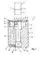
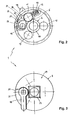
- Figures 1 to 3 show a groove molding tool 1.
- the tool 1 is used to make a groove 2 on the outer surface 3 of a tube 4 To cut stainless steel.
- Figure 1 shows the tube 4 with one already finished cut groove 2.
- the tool 1 has a solid cylindrical housing 5 made of metal, for example made of aluminum.
- a molding space 6 for Receiving the pipe end 7.
- the mold space 6 has an end insertion opening 8 at the end 9 of the housing 5.
- the depth of the molding space 6 is limited by a stop 10.
- the pipe end 7 is in the mold space 6th introduced until it comes to rest on the end face of the stop 10. To this The position of the groove 2 to be created is in the required length distance defined at the tube end 7.
- the mold space 6 is a roller-shaped cutting wheel body 11 and two roller-shaped trained support body 12, 13 assigned.
- the cutting wheel body 11 and the two support bodies 12, 13 are on a pitch circle by 120 ° to each other staggered.
- the two support bodies 12, 13 are rotatable, however fixed in position in the housing 5, whereas the cutting wheel body 11 transverse to its axis of rotation 14 under the influence of a helical compression spring 15 is resiliently stored.
- the helical compression spring 15 is in a transverse direction Blind hole 16 housed.
- FIG. 1 shows the cutting wheel body 11 in the Cutting position S.
- the cutting wheel body 11 and the support body protrude here 12, 13 with parts of their circumference in the molding space 6.
- the lock 17 has an adjustable by a lever 18 and with a circumferential eccentric surface 19 provided clamping body 20. This stands over the eccentric surface 19 with the cylindrical surface 21 of the cutting wheel body 11 in contact.
- the cutting wheel body points in the center 11 a peripheral cutting edge 22.
- On the clamp body 20 is a Cutting edge 22 corresponding groove 23 is provided. This creates a free space so that the cutting edge 22 during the rotational movement of the cutting wheel body 11 can rotate freely.
- the cutting wheel body 11 and the clamping body 20 are arranged in slot-like recesses 24, 25, the one another pass over, so that there is an approximately kidney-shaped configuration.
- the mold space 6 and the cutting wheel body 11 and the support bodies are on the end face 12, 13 covered by a perforated disc 26, which is by means of a Seeger ring 27 is secured.
- the lever 18 is at the end 28 of the housing facing away from the molding space 6 5 arranged on the end face 29 thereof.
- the housing 5 has a paragraph 30 with a free flat surface 31 for the lever 18.
- the depth of the paragraph 30 is selected so that the lever 18 does not go over the end face 29 of the housing 5 survives.
- the lever 18 is connected to the clamping body 20 in the longitudinal direction L connected by the housing 5 extending shaft 32.
- the eccentrically mounted clamping body 20 is rotated. in this connection the arcuate eccentric surface 19 presses the cutting wheel body 11 into the Cutting position S and locks it there.
- the line of action of the helical compression spring 15 and the line of action of those introduced through the eccentric surface Force are designed so that the self-locking of the clamping body 20 in the Cutting position S takes place. This ensures that the lock on the Cutting process cannot be canceled unintentionally.
- the lock 17 must be picked up manually.
- a Receptacle 33 in the form of a square for attaching an operating tool, for example a ratchet is provided at the end 28 of the housing 5 in the end face 29 .
- the housing 5 In the longitudinal direction L. the housing 5 further passes through a central bore 34, which from Bottom of the receptacle 33 opens out into the mold space 6.
- the groove shaping tool 1 is characterized by its compact size small design. That laterally over the diameter of a tube 4 protruding construction volume is low. Handling and operation is easy.
- the groove molding tool 1 is used on site during the assembly work at the front on the pipe end 7.
- the cutting wheel body 11 is released. due to its resilient storage, the cutting wheel body 11 dodge when inserting the pipe end.
- the tube is supported on the support bodies 12, 13.
- the Groove molding tool 1 is then inserted into the receptacle 29 Operating tool rotated. Due to the mechanical force of the Cutting wheel body 11 or the cutting edge 22, the groove 2 on the outer Surface 3 of the tube 4 generated.
Landscapes
- Engineering & Computer Science (AREA)
- Mechanical Engineering (AREA)
- Life Sciences & Earth Sciences (AREA)
- Agronomy & Crop Science (AREA)
- Sawing (AREA)
- Turning (AREA)
- Moulds For Moulding Plastics Or The Like (AREA)
Applications Claiming Priority (2)
| Application Number | Priority Date | Filing Date | Title |
|---|---|---|---|
| DE20207364U DE20207364U1 (de) | 2002-05-08 | 2002-05-08 | Rillenformwerkzeug |
| DE20207364U | 2002-05-08 |
Publications (2)
| Publication Number | Publication Date |
|---|---|
| EP1361007A2 true EP1361007A2 (fr) | 2003-11-12 |
| EP1361007A3 EP1361007A3 (fr) | 2004-01-14 |
Family
ID=7971009
Family Applications (1)
| Application Number | Title | Priority Date | Filing Date |
|---|---|---|---|
| EP03004611A Withdrawn EP1361007A3 (fr) | 2002-05-08 | 2003-03-01 | Outil de formage des rainures |
Country Status (2)
| Country | Link |
|---|---|
| EP (1) | EP1361007A3 (fr) |
| DE (1) | DE20207364U1 (fr) |
Cited By (1)
| Publication number | Priority date | Publication date | Assignee | Title |
|---|---|---|---|---|
| US12121983B1 (en) * | 2023-12-13 | 2024-10-22 | Ronald Kevin Johnston | Tube deburring apparatus and methods of use |
Families Citing this family (1)
| Publication number | Priority date | Publication date | Assignee | Title |
|---|---|---|---|---|
| CH704520B1 (fr) * | 2011-02-24 | 2015-08-14 | Rdi Nov S Rl | Outil de rainurage et procédé d'accouplement d'une première et d'une deuxième parties de tuyaux sanitaires. |
Family Cites Families (8)
| Publication number | Priority date | Publication date | Assignee | Title |
|---|---|---|---|---|
| US2379177A (en) * | 1944-11-17 | 1945-06-26 | Lester J Pavey | Pipe cutter |
| US2769235A (en) * | 1955-03-14 | 1956-11-06 | Arthur E Martois | Portable pipe cutting machine |
| US3535900A (en) * | 1968-11-15 | 1970-10-27 | United States Steel Corp | Apparatus for removing material from cylindrical workpieces |
| US3714712A (en) * | 1971-02-18 | 1973-02-06 | Amp Inc | Cutting or grooving tool |
| US4831732A (en) * | 1984-12-11 | 1989-05-23 | Garton Stephen D | Pipe cutter |
| CH669135A5 (de) * | 1986-04-07 | 1989-02-28 | Fischer Ag Georg | Werkzeug zum abschaelen von rohroberflaechen. |
| CA2003542A1 (fr) * | 1988-11-22 | 1990-05-22 | Clive N. Taylor | Outil a rainure ou a tronconner les tuyaux |
| US5836079A (en) * | 1996-06-03 | 1998-11-17 | Cronin; Michael E. | Pipe cutting tool |
-
2002
- 2002-05-08 DE DE20207364U patent/DE20207364U1/de not_active Expired - Lifetime
-
2003
- 2003-03-01 EP EP03004611A patent/EP1361007A3/fr not_active Withdrawn
Cited By (1)
| Publication number | Priority date | Publication date | Assignee | Title |
|---|---|---|---|---|
| US12121983B1 (en) * | 2023-12-13 | 2024-10-22 | Ronald Kevin Johnston | Tube deburring apparatus and methods of use |
Also Published As
| Publication number | Publication date |
|---|---|
| EP1361007A3 (fr) | 2004-01-14 |
| DE20207364U1 (de) | 2002-08-08 |
Similar Documents
| Publication | Publication Date | Title |
|---|---|---|
| DE7927713U1 (de) | Handgriff fuer ein werkzeug, insbesondere zusatzhandgriff fuer einen bohrhammer | |
| EP0450135B1 (fr) | Perceuse pour l'élimination des points de soudage | |
| EP0304002B1 (fr) | Foret pour perceuse portative, adaptateur porte-visse et procédé pour leur fabrication | |
| DE3335196C1 (de) | Spannvorrichtung für verzahnte Werkstücke | |
| EP1361007A2 (fr) | Outil de formage des rainures | |
| DE102018126093A1 (de) | Verfahren und Vorrichtung zur Herstellung eines Verbindungselementes | |
| DE4428972C1 (de) | Vorrichtung zur lösbaren Festlegung eines zu Verstellzwecken verdrehbaren Handgriffes | |
| EP1095741B1 (fr) | Outil de forage et/ou de percussion | |
| DE8033591U1 (de) | Vorrichtung zur bearbeitung der enden von rohren fuer ihren anschluss | |
| DE3415840A1 (de) | Vorrichtung zum gegenseitigen verschrauben eines aeusseren und eines inneren kegeligen trapez- oder saegengewindes | |
| DE202015000913U1 (de) | Verstellbarer Anfaskopf für eine Rohrendenbearbeitungsstation sowie Rohrendenbearbeitungsstation | |
| DE102018132287A1 (de) | System zum Einstellen der Länge eines Werkzeugs | |
| DE3413285A1 (de) | Spannvorrichtung fuer werkzeuge, wie bohrer, fraeser oder dgl. | |
| DE3807225A1 (de) | Halter fuer ein bohrwerkzeug | |
| DE69033337T2 (de) | Rohrendbearbeitungswerkzeug mit verbesserten Torsionreaktion und Spannmöglichkeiten | |
| DE695728C (de) | Aufspreizbarer Spanndorn mit federnder Spannbuechse | |
| DE1814349A1 (de) | Werkzeug | |
| DE3300503C2 (de) | Kupplungskörper für ein Gartenwerkzeug | |
| DE2129088C3 (de) | Verfahren und Vorrichtung zum Herstellen eines schraubenlinienförmigen Bohrer-Grundkörpers | |
| DE810139C (de) | Werkzeug-Drillvorrichtung | |
| DE212023000204U1 (de) | Fräswerkzeug zum Planfräsen der Stirnfläche eines Rohrendes | |
| DE810497C (de) | Schraubenzieher, Schraubenschluessel o. dgl. mit biegsamer Antriebswelle | |
| DE1552252A1 (de) | Einstellbarer Bohrkopf | |
| DE1752749C3 (de) | Vorrichtung zum Bohren und Aushalsen der Wandung eines Werkstücks | |
| DE519199C (de) | Vorrichtung zum Ausbohren von Pleuelstangen, Lagerschalen u. dgl. |
Legal Events
| Date | Code | Title | Description |
|---|---|---|---|
| PUAI | Public reference made under article 153(3) epc to a published international application that has entered the european phase |
Free format text: ORIGINAL CODE: 0009012 |
|
| AK | Designated contracting states |
Kind code of ref document: A2 Designated state(s): AT BE BG CH CY CZ DE DK EE ES FI FR GB GR HU IE IT LI LU MC NL PT RO SE SI SK TR |
|
| AX | Request for extension of the european patent |
Extension state: AL LT LV MK |
|
| PUAL | Search report despatched |
Free format text: ORIGINAL CODE: 0009013 |
|
| AK | Designated contracting states |
Kind code of ref document: A3 Designated state(s): AT BE BG CH CY CZ DE DK EE ES FI FR GB GR HU IE IT LI LU MC NL PT RO SE SI SK TR |
|
| AX | Request for extension of the european patent |
Extension state: AL LT LV MK |
|
| RIC1 | Information provided on ipc code assigned before grant |
Ipc: 7B 23B 5/16 B Ipc: 7B 21H 7/18 A |
|
| 17P | Request for examination filed |
Effective date: 20040108 |
|
| 17Q | First examination report despatched |
Effective date: 20040521 |
|
| AKX | Designation fees paid |
Designated state(s): AT BE BG CH CY CZ DE DK EE ES FI FR GB GR HU IE IT LI LU MC NL PT RO SE SI SK TR |
|
| STAA | Information on the status of an ep patent application or granted ep patent |
Free format text: STATUS: THE APPLICATION HAS BEEN WITHDRAWN |
|
| 18W | Application withdrawn |
Effective date: 20041217 |