EP1361007A2 - Groove forming tool - Google Patents
Groove forming tool Download PDFInfo
- Publication number
- EP1361007A2 EP1361007A2 EP03004611A EP03004611A EP1361007A2 EP 1361007 A2 EP1361007 A2 EP 1361007A2 EP 03004611 A EP03004611 A EP 03004611A EP 03004611 A EP03004611 A EP 03004611A EP 1361007 A2 EP1361007 A2 EP 1361007A2
- Authority
- EP
- European Patent Office
- Prior art keywords
- housing
- cutting wheel
- tool
- wheel body
- tool according
- Prior art date
- Legal status (The legal status is an assumption and is not a legal conclusion. Google has not performed a legal analysis and makes no representation as to the accuracy of the status listed.)
- Withdrawn
Links
Images
Classifications
-
- B—PERFORMING OPERATIONS; TRANSPORTING
- B21—MECHANICAL METAL-WORKING WITHOUT ESSENTIALLY REMOVING MATERIAL; PUNCHING METAL
- B21H—MAKING PARTICULAR METAL OBJECTS BY ROLLING, e.g. SCREWS, WHEELS, RINGS, BARRELS, BALLS
- B21H7/00—Making articles not provided for in the preceding groups, e.g. agricultural tools, dinner forks, knives, spoons
- B21H7/18—Making articles not provided for in the preceding groups, e.g. agricultural tools, dinner forks, knives, spoons grooved pins; Rolling grooves, e.g. oil grooves, in articles
- B21H7/182—Rolling annular grooves
-
- B—PERFORMING OPERATIONS; TRANSPORTING
- B23—MACHINE TOOLS; METAL-WORKING NOT OTHERWISE PROVIDED FOR
- B23B—TURNING; BORING
- B23B5/00—Turning-machines or devices specially adapted for particular work; Accessories specially adapted therefor
- B23B5/16—Turning-machines or devices specially adapted for particular work; Accessories specially adapted therefor for bevelling, chamfering, or deburring the ends of bars or tubes
- B23B5/167—Tools for chamfering the ends of bars or tubes
- B23B5/168—Tools for chamfering the ends of bars or tubes with guiding devices
Definitions
- the invention relates to a tool for forming a groove on the outer Surface of a pipe according to the features in the preamble of protection claim 1.
- a larger-sized groove molding tool is known. It has been developed around a defined groove at a predetermined distance at the end of the pipe Cut stainless steel pipe. The groove is used to hold an O-ring, around the pipe then with connection components, for example T-shaped or angular Screw-in or plug connections via a so-called flash or Connect quick connection system.
- the known tool has a housing with one provided therein Mold cavity. This is supported by two rotatable support rollers and one Cutting wheel formed, which over a spindle by means of a knurled wheel is adjustable. By adjusting the cutting wheel, the molding space can be opened different pipe diameters can be adjusted.
- the pipe end is pushed into the molding space. Then the cutting wheel body is activated by operating the knurled wheel turned down to the stainless steel tube and the device so long around the tube axis rotated until the desired groove is created.
- the known tool has basically proven itself in practice. It works reliable for different diameters. However, it builds in radial Comparatively large direction. This is particularly true in use cases limited space required, for example, when processing individual, in one Pipe bundle arranged pipes disadvantageous, since here the necessary lateral There is no space for turning the device around the pipe. This makes the assembly work cumbersome and can also injure the Hands push the tool through the neighboring pipe ends to lead.
- the invention is based on the object a compact groove shaping tool which is improved in handling create.
- this object is achieved in a tool according to the features of claim 1, in the general inventive concept the mold space at least one support body and a cutting wheel body are assigned, each individually or both in the housing resiliently supported and by means of a lock in the cutting position can be locked.
- the configuration according to the invention enables a very compact, simple manageable design of the tool.
- the tool can move in the axial direction be pushed onto the end of a pipe and operated from the front. By a turn the desired groove is created around the pipe.
- the operation of the grooving tool takes place from in front of the head facing away from the mold space End of the tool. Lateral is for the rotation of the tool only a small amount of space is required.
- the Molding space can also be designed adjustable in diameter.
- both the cutting wheel body and the support body can be resiliently mounted in the housing.
- the grooving tool can with the molding space from the front axially on the machined End of the pipe.
- the cutting wheel body or the support body yield resiliently. Then the cutting wheel body and / or the support body is locked in the cutting position by the lock.
- the tool according to the invention particularly advantageously has a roller-shaped one Cutting wheel body and two roll-shaped support bodies, which are each offset on a pitch circle by 120 °.
- the support body are rotatably fixed in position, whereas the cutting body transversely its axis of rotation can be shifted under the influence of a helical compression spring is.
- the housing is preferably cylindrical.
- the cutting wheel body and the support bodies protrude at least in the cutting position with parts of their Circumference in the mold space.
- the lock preferably that of the cutting wheel body, has one a lever adjustable and provided with a peripheral eccentric surface Clamp body.
- the clamp body is also configured in a roll-like manner and stored eccentrically.
- the eccentric surface is grooved and is cylindrical with the designed surface of the cutting wheel body in contact.
- the in the The eccentric surface provided groove serves as free space for those on the cutting wheel body provided circumferential cutting edge.
- the lever on the the end of the housing facing away from the molding space and with the Clamping body over a longitudinally extending through the housing Shaft is connected.
- This contributes significantly to the compact and easy to handle Design of the tool according to the invention.
- the tool will from the front onto the pipe end and the cutting wheel body is then by operating the lever via the clamping body in the cutting position locked.
- the groove is created by turning the tool around the pipe axis.
- the housing has a receptacle for attaching an actuating tool. This is convenient on the end face of the housing opposite the molding space intended.
- the recording can be in the form of a square, for example be designed using a ratchet or similar operating tool can be applied.
- the practical application is also supported when there is a stop in the molding space is provided, at which the pipe end to be machined with its end face comes to the plant.
- the stop is the defined distance the groove to the free end of the pipe.
- Figures 1 to 3 show a groove molding tool 1.
- the tool 1 is used to make a groove 2 on the outer surface 3 of a tube 4 To cut stainless steel.
- Figure 1 shows the tube 4 with one already finished cut groove 2.
- the tool 1 has a solid cylindrical housing 5 made of metal, for example made of aluminum.
- a molding space 6 for Receiving the pipe end 7.
- the mold space 6 has an end insertion opening 8 at the end 9 of the housing 5.
- the depth of the molding space 6 is limited by a stop 10.
- the pipe end 7 is in the mold space 6th introduced until it comes to rest on the end face of the stop 10. To this The position of the groove 2 to be created is in the required length distance defined at the tube end 7.
- the mold space 6 is a roller-shaped cutting wheel body 11 and two roller-shaped trained support body 12, 13 assigned.
- the cutting wheel body 11 and the two support bodies 12, 13 are on a pitch circle by 120 ° to each other staggered.
- the two support bodies 12, 13 are rotatable, however fixed in position in the housing 5, whereas the cutting wheel body 11 transverse to its axis of rotation 14 under the influence of a helical compression spring 15 is resiliently stored.
- the helical compression spring 15 is in a transverse direction Blind hole 16 housed.
- FIG. 1 shows the cutting wheel body 11 in the Cutting position S.
- the cutting wheel body 11 and the support body protrude here 12, 13 with parts of their circumference in the molding space 6.
- the lock 17 has an adjustable by a lever 18 and with a circumferential eccentric surface 19 provided clamping body 20. This stands over the eccentric surface 19 with the cylindrical surface 21 of the cutting wheel body 11 in contact.
- the cutting wheel body points in the center 11 a peripheral cutting edge 22.
- On the clamp body 20 is a Cutting edge 22 corresponding groove 23 is provided. This creates a free space so that the cutting edge 22 during the rotational movement of the cutting wheel body 11 can rotate freely.
- the cutting wheel body 11 and the clamping body 20 are arranged in slot-like recesses 24, 25, the one another pass over, so that there is an approximately kidney-shaped configuration.
- the mold space 6 and the cutting wheel body 11 and the support bodies are on the end face 12, 13 covered by a perforated disc 26, which is by means of a Seeger ring 27 is secured.
- the lever 18 is at the end 28 of the housing facing away from the molding space 6 5 arranged on the end face 29 thereof.
- the housing 5 has a paragraph 30 with a free flat surface 31 for the lever 18.
- the depth of the paragraph 30 is selected so that the lever 18 does not go over the end face 29 of the housing 5 survives.
- the lever 18 is connected to the clamping body 20 in the longitudinal direction L connected by the housing 5 extending shaft 32.
- the eccentrically mounted clamping body 20 is rotated. in this connection the arcuate eccentric surface 19 presses the cutting wheel body 11 into the Cutting position S and locks it there.
- the line of action of the helical compression spring 15 and the line of action of those introduced through the eccentric surface Force are designed so that the self-locking of the clamping body 20 in the Cutting position S takes place. This ensures that the lock on the Cutting process cannot be canceled unintentionally.
- the lock 17 must be picked up manually.
- a Receptacle 33 in the form of a square for attaching an operating tool, for example a ratchet is provided at the end 28 of the housing 5 in the end face 29 .
- the housing 5 In the longitudinal direction L. the housing 5 further passes through a central bore 34, which from Bottom of the receptacle 33 opens out into the mold space 6.
- the groove shaping tool 1 is characterized by its compact size small design. That laterally over the diameter of a tube 4 protruding construction volume is low. Handling and operation is easy.
- the groove molding tool 1 is used on site during the assembly work at the front on the pipe end 7.
- the cutting wheel body 11 is released. due to its resilient storage, the cutting wheel body 11 dodge when inserting the pipe end.
- the tube is supported on the support bodies 12, 13.
- the Groove molding tool 1 is then inserted into the receptacle 29 Operating tool rotated. Due to the mechanical force of the Cutting wheel body 11 or the cutting edge 22, the groove 2 on the outer Surface 3 of the tube 4 generated.
Landscapes
- Engineering & Computer Science (AREA)
- Mechanical Engineering (AREA)
- Life Sciences & Earth Sciences (AREA)
- Agronomy & Crop Science (AREA)
- Sawing (AREA)
- Turning (AREA)
- Moulds For Moulding Plastics Or The Like (AREA)
Abstract
Die Erfindung betrifft ein Werkzeug zum Formen einer Rille (2) an der äußeren Oberfläche (3) eines Rohrs (4). Das Werkzeug weist ein Gehäuse (5) mit einem hierin ausgebildeten Formraum (6) zur Aufnahme eines Rohrendes (7) auf. Im Formraum (6) ist zumindest ein Stützkörper (12, 13) und ein Schneidradkörper (11) vorgesehen, wobei der Schneidradkörper (11) und/oder der Stützkörper (12, 13) im Gehäuse (5) federnd nachgiebig gelagert und mittels eienr Verriegelung (17) in der Schneidposition (S) arretierbar sind. Vorzugsweise sind im Formraum (6) ein Schneidradkörper (11) und zwei rollenförmig ausgebildete Stützkörper (12, 13) auf einem Teilkreis um jeweils 120° versetzt angeordnet. <IMAGE>The invention relates to a tool for forming a groove (2) on the outer surface (3) of a tube (4). The tool has a housing (5) with a molding space (6) formed therein for receiving a pipe end (7). At least one support body (12, 13) and a cutting wheel body (11) are provided in the molding space (6), the cutting wheel body (11) and / or the support body (12, 13) being resiliently mounted in the housing (5) and by means of a locking mechanism (17) can be locked in the cutting position (S). Preferably, a cutting wheel body (11) and two roller-shaped support bodies (12, 13) are arranged offset by 120 ° on a pitch circle in the molding space (6). <IMAGE>
Description
Die Erfindung betrifft ein Werkzeug zum Formen einer Rille an der äußeren
Oberfläche eines Rohrs gemäß den Merkmalen im Oberbegriff von Schutzanspruch
1.The invention relates to a tool for forming a groove on the outer
Surface of a pipe according to the features in the preamble of
Ein gattungsgrößeres Rillenformwerkzeug ist bekannt. Es ist entwickelt worden, um eine definierte Rille in einem vorgegebenen Abstand am Rohrende eines Edelstahlrohrs einzuschneiden. Die Rille dient zur Aufnahme eines O-Rings, um das Rohr dann mit Anschlussbauteilen beispielsweise T- oder winkelförmigen Einschraub- oder Steckanschlüssen über ein sogenanntes Blitz- oder Schnellanschlusssystem zu verbinden.A larger-sized groove molding tool is known. It has been developed around a defined groove at a predetermined distance at the end of the pipe Cut stainless steel pipe. The groove is used to hold an O-ring, around the pipe then with connection components, for example T-shaped or angular Screw-in or plug connections via a so-called flash or Connect quick connection system.
Das bekannte Werkzeug weist ein Gehäuse auf mit einem hierin vorgesehenen Formraum. Dieser wird durch zwei fixiert drehbar gelagerte Stützrollen und ein Schneidrad gebildet, welches über eine Spindel mittels eines Rändelrades einstellbar ist. Durch die Verstellung des Schneidrades kann der Formraum auf verschiedene Rohrdurchmesser angepasst werden.The known tool has a housing with one provided therein Mold cavity. This is supported by two rotatable support rollers and one Cutting wheel formed, which over a spindle by means of a knurled wheel is adjustable. By adjusting the cutting wheel, the molding space can be opened different pipe diameters can be adjusted.
Um eine Rille zu schneiden wird das Rohrende in den Formraum eingeschoben. Anschließend wird der Schneidradkörper durch Betätigung des Rändelrades bis auf das Edelstahlrohr zugedreht und das Gerät so lange um die Rohrachse gedreht bis die gewünschte Rille erzeugt ist.In order to cut a groove, the pipe end is pushed into the molding space. Then the cutting wheel body is activated by operating the knurled wheel turned down to the stainless steel tube and the device so long around the tube axis rotated until the desired groove is created.
Das bekannte Werkzeug hat sich in der Praxis grundsätzlich bewährt. Es arbeitet zuverlässig für verschiedene Durchmesser. Es baut jedoch in radialer Richtung vergleichsweise groß. Dies ist insbesondere in Anwendungsfällen mit begrenztem Platzbedarf beispielsweise bei der Bearbeitung einzelner, in einem Rohrbündel angeordneter Rohre nachteilig, da hier der notwendige seitliche Freiraum für das Drehen des Gerätes um das Rohr nicht vorhanden ist. Dies macht die Montagearbeiten umständlich und kann auch zu Verletzungen der Hände beim Betätigen des Werkzeugs durch die benachbarten Rohrenden führen.The known tool has basically proven itself in practice. It works reliable for different diameters. However, it builds in radial Comparatively large direction. This is particularly true in use cases limited space required, for example, when processing individual, in one Pipe bundle arranged pipes disadvantageous, since here the necessary lateral There is no space for turning the device around the pipe. This makes the assembly work cumbersome and can also injure the Hands push the tool through the neighboring pipe ends to lead.
Der Erfindung liegt ausgehend vom Stand der Technik die Aufgabe zugrunde, ein in der Handhabung verbessertes kompakt bauendes Rillenformwerkzeug zu schaffen.Based on the prior art, the invention is based on the object a compact groove shaping tool which is improved in handling create.
Die Lösung dieser Aufgabe besteht nach der Erfindung in einem Werkzeug
gemäß den Merkmalen von Schutzanspruch 1, bei dem im allgemeinen Erfindungsgedanken
dem Formraum zumindest ein Stützkörper und ein Schneidradkörper
zugeordnet sind, die jeweils einzeln oder auch beide im Gehäuse
federnd nachgiebig gelagert und mittels einer Verriegelung in der Schneidposition
arretierbar sind.According to the invention, this object is achieved in a tool
according to the features of
Die erfindungsgemäße Ausgestaltung ermöglicht eine sehr kompakte einfach handhabbare Bauform des Werkzeugs. Das Werkzeug kann in axialer Richtung von vorne auf ein Rohrende aufgesteckt und betätigt werden. Durch eine Drehung um das Rohr wird die gewünschte Rille erstellt. Die Betätigung des Rillenformwerkzeugs erfolgt von vor Kopf also von dem dem Formraum abgewandten Ende des Werkzeugs aus. Seitlich ist für die Drehung des Werkzeugs nur ein geringer Platzbedarf notwendig.The configuration according to the invention enables a very compact, simple manageable design of the tool. The tool can move in the axial direction be pushed onto the end of a pipe and operated from the front. By a turn the desired groove is created around the pipe. The operation of the grooving tool takes place from in front of the head facing away from the mold space End of the tool. Lateral is for the rotation of the tool only a small amount of space is required.
Für die Praxis ist vorgesehen, dass jeweils für einen bestimmten Rohrdurchmesser ein Rillenformwerkzeug zur Verfügung steht. Grundsätzlich kann der Formraum aber auch im Durchmesser verstellbar konzipiert werden.In practice it is provided that for a certain pipe diameter a grooving tool is available. Basically, the Molding space can also be designed adjustable in diameter.
Vorteilhafte Ausgestaltungen und Weiterbildungen des grundsätzlilchen Erfindungsgedankens
bilden Gegenstand der abhängigen Ansprüche 2 bis 10.Advantageous refinements and developments of the basic inventive concept
form the subject of
Im allgemeinen Erfindungsgedanken kann sowohl der Schneidradkörper als auch der Stützkörper im Gehäuse federnd nachgiebig gelagert sein. Das Rillenformwerkzeug kann mit dem Formraum von vorn axial auf das zu bearbeitende Rohrende gesetzt werden. Hierbei können der Schneidradkörper bzw. der Stützkörper federnd nachgeben. Anschließend wird der Schneidradkörper und/oder der Stützkörper durch die Verriegelung in der Schneidposition arretiert.In general, both the cutting wheel body and the support body can be resiliently mounted in the housing. The grooving tool can with the molding space from the front axially on the machined End of the pipe. The cutting wheel body or the support body yield resiliently. Then the cutting wheel body and / or the support body is locked in the cutting position by the lock.
Besonders vorteilhaft weist das erfindungsgemäße Werkzeug einen rollenförmigen Schneidradkörper und zwei rollenförmig ausgebildete Stützkörper auf, die jeweils auf einem Teilkreis um 120° versetzt angeordnet sind. Die Stützkörper sind drehbar lagefixiert angeordnet, wohingegen der Schneidkörper quer zu seiner Drehachse unter dem Einfluss einer Schraubendruckfeder verlagerbar ist.The tool according to the invention particularly advantageously has a roller-shaped one Cutting wheel body and two roll-shaped support bodies, which are each offset on a pitch circle by 120 °. The support body are rotatably fixed in position, whereas the cutting body transversely its axis of rotation can be shifted under the influence of a helical compression spring is.
Das Gehäuse ist vorzugsweise zylindrisch ausgeführt. Der Schneidradkörper und die Stützkörper ragen zumindest in der Schneidposition mit Teilen ihres Umfangs in den Formraum.The housing is preferably cylindrical. The cutting wheel body and the support bodies protrude at least in the cutting position with parts of their Circumference in the mold space.
Die Verriegelung, vorzugsweise die des Schneidradkörpers weist einen durch einen Hebel verstellbaren und mit einer umfangsseitigen Exzenterfläche versehenen Klemmkörper auf. Der Klemmkörper ist ebenfalls rollenartig konfiguriert und exzentrisch gelagert. Die Exzenterfläche ist genutet und steht mit der zylindrisch gestalteten Oberfläche des Schneidradkörpers in Kontakt. Die in der Exzenterfläche vorgesehene Nut dient als Freiraum für die am Schneidradkörper vorgesehene umlaufende Schneide.The lock, preferably that of the cutting wheel body, has one a lever adjustable and provided with a peripheral eccentric surface Clamp body. The clamp body is also configured in a roll-like manner and stored eccentrically. The eccentric surface is grooved and is cylindrical with the designed surface of the cutting wheel body in contact. The in the The eccentric surface provided groove serves as free space for those on the cutting wheel body provided circumferential cutting edge.
Im Rahmen der Erfindung ist insbesondere vorteilhaft, wenn der Hebel an dem dem Formraum abgewandten Ende des Gehäuses angeordnet und mit dem Klemmkörper über eine sich in Längsrichtung durch das Gehäuse erstreckende Welle verbunden ist. Dies trägt wesentlich zur kompakten und einfach handhabbaren Bauart des erfindungsgemäßen Werkzeugs bei. Das Werkzeug wird von vorne auf das Rohrende aufgesteckt und der Schneidradkörper wird dann durch Betätigung des Hebels über den Klemmkörper in der Schneidposition arretiert. Durch Drehen des Werkzeugs um die Rohrachse wird die Rille erstellt. In diesem Zusammenhang ist ferner vorteilhaft, wenn das Gehäuse eine Aufnahme zum Ansetzen eines Betätigungswerkzeugs aufweist. Diese ist zweckmäßigerweise an der dem Formraum gegenüberliegenden Stirnseite des Gehäuses vorgesehen. Die Aufnahme kann beispielsweise in Form eines Vierkantes gestaltet sein, über den eine Ratsche oder ein ähnliches Betätigungswerkzeug angesetzt werden kann.In the context of the invention it is particularly advantageous if the lever on the the end of the housing facing away from the molding space and with the Clamping body over a longitudinally extending through the housing Shaft is connected. This contributes significantly to the compact and easy to handle Design of the tool according to the invention. The tool will from the front onto the pipe end and the cutting wheel body is then by operating the lever via the clamping body in the cutting position locked. The groove is created by turning the tool around the pipe axis. In this context, it is also advantageous if the housing has a receptacle for attaching an actuating tool. This is convenient on the end face of the housing opposite the molding space intended. The recording can be in the form of a square, for example be designed using a ratchet or similar operating tool can be applied.
Die praktische Anwendung wird ferner unterstützt, wenn im Formraum ein Anschlag vorgesehen ist, an den das zu bearbeitende Rohrende mit seiner Stirnseite zur Anlage gelangt. Durch den Anschlag ist folglich der definierte Abstand der Rille zum freien Ende des Rohres vorgegeben.The practical application is also supported when there is a stop in the molding space is provided, at which the pipe end to be machined with its end face comes to the plant. The stop is the defined distance the groove to the free end of the pipe.
Für die Praxis ist geplant, jeweils ein einzelnes Werkzeug für einen bestimmten Rohrdurchmesser vorzusehen. Zweckmäßigerweise wird für die praktische Anwendung ein Satz von einzelnen Werkzeugen bereitgestellt, abgestimmt auf die notwendigen Rohrdurchmesser. Demzufolge sind zwar verschiedene Werkzeuge für unterschiedliche Rohrdurchmesser notwendig, diese einzelnen Werkzeuge können jedoch verwechslungsfrei gekennzeichnet werden, was zu einer Vereinfachung in der Handhabung führt. Gerade unter Montage-Bedingungen, beispielsweise in begrenzten Räumlichkeiten und unter Umständen ölverschmierter Umgebung, ist ein präzises Einstellen des Werkzeugs auf den jeweils erforderlichen Rohrdurchmesser schwierig. Dies wird nun vermieden. Der Monteur nimmt das jeweils passende Werkzeug und steckt dieses auf ein Rohrende. Das Rillenformwerkzeug wird dann durch Umlegen des Hebels arretiert und unter Zuhilfenahme eines Betätigungswerkzeuges gedreht.In practice, it is planned to use a single tool for a specific one To provide pipe diameter. Expediently for the practical Application provided a set of individual tools tailored to the necessary pipe diameters. As a result, they are different tools necessary for different pipe diameters, these individual However, tools can be labeled without confusion, which leads to simplifies handling. Especially under assembly conditions, for example in limited spaces and under certain circumstances oil-smeared environment, is a precise adjustment of the tool to the each pipe diameter required difficult. This is now avoided. The fitter takes the appropriate tool and puts it on Pipe end. The groove forming tool is then turned by moving the lever locked and rotated with the help of an operating tool.
Die Erfindung ist nachfolgend anhand eines in den Zeichnungen dargestellten Ausführungsbeispiels näher beschrieben. Es zeigen:
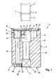
Figur 1- ein erfindungsgemäßes Werkzeug im vertikalen Längsschnitt;
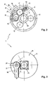
Figur 2- eine Draufsicht, teilweise in geschnittener Darstellungsweise auf
die Darstellung der
Figur 1 gemäß dem Pfeil II und Figur 3- eine Stirnansicht auf das Werkzeug gemäß dem Pfeil III.
- Figure 1
- an inventive tool in vertical longitudinal section;
- Figure 2
- a plan view, partly in section on the representation of Figure 1 according to the arrow II and
- Figure 3
- an end view of the tool according to arrow III.
Die Figuren 1 bis 3 zeigen ein Rillenformwerkzeug 1. Das Werkzeug 1 wird
eingesetzt, um eine Rille 2 an der äußeren Oberfläche 3 eines Rohrs 4 aus
Edelstahl zu schneiden. Die Figur 1 zeigt das Rohr 4 mit einer bereits fertig
geschnittenen Rille 2.Figures 1 to 3 show a
Das Werkzeug 1 weist ein massives zylindrisches Gehäuse 5 aus Metall auf,
beispielsweise aus Aluminium. Im Gehäuse 5 befindet sich ein Formraum 6 zur
Aufnahme des Rohrendes 7. Der Formraum 6 weist eine stirnseitige Einführöffnung
8 am Ende 9 des Gehäuses 5 auf. Die Tiefe des Formraums 6 ist begrenzt
durch einen Anschlag 10. Das Rohrende 7 wird in den Formraum 6
eingeführt, bis es stirnseitig am Anschlag 10 zur Anlage gelangt. Auf diese
Weise ist die Position der zu erstellenden Rille 2 in dem erforderlichen Längenabstand
am Rohrende 7 definiert.The
Dem Formraum 6 ist ein rollenförmiger Schneidradkörper 11 und zwei rollenförmig
ausgebildete Stützkörper 12, 13 zugeordnet. Der Schneidradkörper 11 und
die beiden Stützkörper 12, 13 sind auf einem Teilkreis um jeweils 120° zueinander
versetzt angeordnet. Die beiden Stützkörper 12, 13 sind drehbar, jedoch
lagefixiert im Gehäuse 5 angeordnet, wohingegen der Schneidradkörper 11
quer zu seiner Drehachse 14 unter dem Einfluss einer Schraubendruckfeder 15
nachgiebig gelagert ist. Die Schraubendruckfeder 15 ist in einer quergerichteten
Sackbohrung 16 untergebracht.The
Mittels einer Verriegelung 17 kann der Schneidradkörper 11 in der Schneidposition
S arretiert werden. Figur 2 zeigt den Schneidradkörper 11 in der
Schneidposition S. Hierbei ragen der Schneidradkörper 11 und die Stützkörper
12, 13 mit Teilen ihres Umfangs in den Formraum 6.By means of a
Die Verriegelung 17 weist einen durch einen Hebel 18 verstellbaren und mit
einer umfangsseitigen Exzenterfläche 19 versehenen Klemmkörper 20 auf.
Dieser steht über die Exzenterfläche 19 mit der zylindrisch gestalteten Oberfläche
21 des Schneidradkörpers 11 in Kontakt. Mittig weist der Schneidradkörper
11 eine umlaufende Schneide 22 auf. Am Klemmkörper 20 ist eine zur
Schneide 22 korrespondierende Nut 23 vorgesehen. Diese schafft einen Freiraum,
so dass sich die Schneide 22 bei der Drehbewegung des Schneidradkörpers
11 frei drehen kann. Der Schneidradkörper 11 und der Klemmkörper 20
sind in langlochartigen Ausnehmungen 24, 25 angeordnet, die ineinander
übergehen, so dass sich eine etwa nierenförmige Konfiguration ergibt.The
Stirnseitig sind der Formraum 6 sowie der Schneidradkörper 11 und die Stützkörper
12, 13 durch eine Lochscheibe 26 abgedeckt, die mittels eines Seeger-Rings
27 gesichert ist.The
Der Hebel 18 ist an dem, dem Formraum 6 abgewandten Ende 28 des Gehäuses
5 an dessen Stirnseite 29 angeordnet. Hier weist das Gehäuse 5 einen Absatz
30 mit einer freien Planfläche 31 für den Hebel 18 auf. Die Tiefe des Absatz
30 ist so gewählt, das der Hebel 18 nicht über die Stirnseite 29 des Gehäuses
5 übersteht. The
Der Hebel 18 ist mit dem Klemmkörper 20 über eine sich in Längsrichtung L
durch das Gehäuse 5 erstreckende Welle 32 verbunden. Durch Umlegen des
Hebels 18 wird der exzentrisch gelagerte Klemmkörper 20 gedreht. Hierbei
drückt die bogenförmige Exzenterfläche 19 den Schneidradkörper 11 in die
Schneidposition S und arretiert diesen dort. Die Wirkungslinie der Schraubendruckfeder
15 und die Wirkungslinie der durch die Exzenterfläche eingeleiteten
Kraft sind so konzipiert, dass eine Selbsthemmung des Klemmkörpers 20 in der
Schneidposition S erfolgt. Dies gewährleistet, dass die Arretierung beim
Schneidvorgang nicht ungewollt aufgehoben werden kann. Die Verriegelung 17
muss manuell aufgehoben werden.The
Man erkennt ferner, dass am Ende 28 des Gehäuses 5 in der Stirnseite 29 eine
Aufnahme 33 in Form eines Vierkants zum Ansetzen eines Betätigungswerkzeugs,
beispielweise einer Ratsche, vorgesehen ist. In Längsrichtung L wird
das Gehäuse 5 ferner von einer zentralen Bohrung 34 durchsetzt, welches vom
Boden der Aufnahme 33 ausgehend in den Formraum 6 mündet.It can also be seen that at the
Das erfindungsgemäße Rillenformwerkzeug 1 zeichnet sich durch seine kompakte
kleine Bauform aus. Das seitlich über den Durchmesser eines Rohrs 4
überstehende Bauvolumen ist gering. Die Handhabung und Betätigung ist einfach.
Das Rillenformwerkzeug 1 wird vor Ort während der Montagearbeiten von
vorne auf das Rohrende 7 gesteckt. Hierbei ist der Schneidradkörper 11 gelöst.
auf Grund seiner federnd nachgiebigen Lagerung kann der Schneidradkörper
11 beim Einführen des Rohrendes ausweichen. Anschließend wird der
Schneidradkörper in der Schneidposition S mittels der Verriegelung 17 arretiert.
Dies geschieht durch Umlegen des Hebels 18, ebenfalls vom freien Ende 28
aus. Im Formraum 6 ist das Rohr an den Stützkörpern 12, 13 abgestützt. Das
Rillenformwerkzeug 1 wird dann mittels eines in die Aufnahme 29 eingesetzten
Betätigungswerkzeugs gedreht. Durch die mechanische Krafteinwirkung des
Schneidradkörpers 11 bzw. der Schneide 22 wird die Rille 2 an der äußeren
Oberfläche 3 des Rohrs 4 erzeugt. The
- 1 -1 -
- RillenformwerkzeugGrooves mold
- 2 -2 -
- Rillegroove
- 3 -3 -
- äußere Oberfläche v. 4outer surface v. 4
- 4 -4 -
- Rohrpipe
- 5 -5 -
- Gehäusecasing
- 6 -6 -
- Formraumcavity
- 7 -7 -
- Rohrendepipe end
- 8 -8th -
- Einführöffnunginsertion
- 9 -9 -
- Ende v. 5End of v. 5
- 10 -10 -
- Anschlagattack
- 11 -11 -
- SchneidradkörperSchneidradkörper
- 12 -12 -
- Stützkörpersupport body
- 13 -13 -
- Stützköpersupport body
- 14 -14 -
- Drehachseaxis of rotation
- 15 -15 -
- SchraubendruckfederHelical compression spring
- 16 -16 -
- Sackbohrungblind hole
- 17 -17 -
- Verriegelunglock
- 18 -18 -
- Hebellever
- 19 -19 -
- Exzenterflächeeccentric
- 20 -20 -
- Klemmkörperclamping bodies
- 21 -21 -
- Oberfläche v. 11Surface v. 11
- 22 -22 -
- Schneidecutting edge
- 23 -23 -
- Nutgroove
- 24 -24 -
- Ausnehmungrecess
- 25 -25 -
- Ausnehmungrecess
- 26 -26 -
- Lochscheibeperforated disc
- 27 -27 -
- Seeger-RingSeeger ring
- 28 -28 -
- Ende v. 5 End of v. 5
- 29 -29 -
- Stirnseitefront
- 30 -30 -
- Absatzparagraph
- 31 -31 -
- Planflächeplane surface
- 32 -32 -
- Wellewave
- 33 -33 -
- Aufnahmeadmission
- 34 -34 -
- Bohrungdrilling
- S -S -
- Schneidpositioncutting position
- L -L -
- Längsrichtung v. 5Longitudinal direction v. 5
Claims (10)
Applications Claiming Priority (2)
| Application Number | Priority Date | Filing Date | Title |
|---|---|---|---|
| DE20207364U DE20207364U1 (en) | 2002-05-08 | 2002-05-08 | Grooves mold |
| DE20207364U | 2002-05-08 |
Publications (2)
| Publication Number | Publication Date |
|---|---|
| EP1361007A2 true EP1361007A2 (en) | 2003-11-12 |
| EP1361007A3 EP1361007A3 (en) | 2004-01-14 |
Family
ID=7971009
Family Applications (1)
| Application Number | Title | Priority Date | Filing Date |
|---|---|---|---|
| EP03004611A Withdrawn EP1361007A3 (en) | 2002-05-08 | 2003-03-01 | Groove forming tool |
Country Status (2)
| Country | Link |
|---|---|
| EP (1) | EP1361007A3 (en) |
| DE (1) | DE20207364U1 (en) |
Cited By (1)
| Publication number | Priority date | Publication date | Assignee | Title |
|---|---|---|---|---|
| US12121983B1 (en) * | 2023-12-13 | 2024-10-22 | Ronald Kevin Johnston | Tube deburring apparatus and methods of use |
Families Citing this family (1)
| Publication number | Priority date | Publication date | Assignee | Title |
|---|---|---|---|---|
| CH704520B1 (en) * | 2011-02-24 | 2015-08-14 | Rdi Nov S Rl | grooving tool and method of coupling a first and a second portions sanitary pipes. |
Family Cites Families (8)
| Publication number | Priority date | Publication date | Assignee | Title |
|---|---|---|---|---|
| US2379177A (en) * | 1944-11-17 | 1945-06-26 | Lester J Pavey | Pipe cutter |
| US2769235A (en) * | 1955-03-14 | 1956-11-06 | Arthur E Martois | Portable pipe cutting machine |
| US3535900A (en) * | 1968-11-15 | 1970-10-27 | United States Steel Corp | Apparatus for removing material from cylindrical workpieces |
| US3714712A (en) * | 1971-02-18 | 1973-02-06 | Amp Inc | Cutting or grooving tool |
| US4831732A (en) * | 1984-12-11 | 1989-05-23 | Garton Stephen D | Pipe cutter |
| CH669135A5 (en) * | 1986-04-07 | 1989-02-28 | Fischer Ag Georg | TOOL FOR PEELING PIPE SURFACES. |
| CA2003542A1 (en) * | 1988-11-22 | 1990-05-22 | Clive N. Taylor | Tool for grooving or cutting pipes |
| US5836079A (en) * | 1996-06-03 | 1998-11-17 | Cronin; Michael E. | Pipe cutting tool |
-
2002
- 2002-05-08 DE DE20207364U patent/DE20207364U1/en not_active Expired - Lifetime
-
2003
- 2003-03-01 EP EP03004611A patent/EP1361007A3/en not_active Withdrawn
Cited By (1)
| Publication number | Priority date | Publication date | Assignee | Title |
|---|---|---|---|---|
| US12121983B1 (en) * | 2023-12-13 | 2024-10-22 | Ronald Kevin Johnston | Tube deburring apparatus and methods of use |
Also Published As
| Publication number | Publication date |
|---|---|
| EP1361007A3 (en) | 2004-01-14 |
| DE20207364U1 (en) | 2002-08-08 |
Similar Documents
| Publication | Publication Date | Title |
|---|---|---|
| DE7927713U1 (en) | HANDLE FOR A TOOL, IN PARTICULAR ADDITIONAL HANDLE FOR A DRILLING HAMMER | |
| EP0450135B1 (en) | Hand-drill for drilling-out of spot-welds | |
| EP0304002B1 (en) | Drill for portable drilling machine, screw holding bit and method for manufacturing these tools | |
| DE3335196C1 (en) | Clamping device for toothed workpieces | |
| EP1361007A2 (en) | Groove forming tool | |
| DE102018126093A1 (en) | Method and device for producing a connecting element | |
| DE4428972C1 (en) | Device for releasably fixing a handle that can be rotated for adjustment purposes | |
| EP1095741B1 (en) | Drilling and/or percussion tool | |
| DE8033591U1 (en) | DEVICE FOR MACHINING THE END OF PIPES FOR THEIR CONNECTION | |
| DE3415840A1 (en) | DEVICE FOR MUTUAL SCREWING OF AN EXTERNAL AND INNER TAPERED KEYSTONE OR SAW THREAD | |
| DE202015000913U1 (en) | Adjustable chamfering head for a pipe end processing station and pipe end processing station | |
| DE102018132287A1 (en) | System for adjusting the length of a tool | |
| DE3413285A1 (en) | CLAMPING DEVICE FOR TOOLS LIKE DRILLING, MILLING OR THE LIKE | |
| DE3807225A1 (en) | Holder for a drilling tool | |
| DE69033337T2 (en) | Pipe finishing tool with improved torsion response and clamping options | |
| DE695728C (en) | Expandable mandrel with spring-loaded clamping sleeve | |
| DE1814349A1 (en) | Tool | |
| DE3300503C2 (en) | Coupling body for a garden tool | |
| DE2129088C3 (en) | Method and device for producing a helical drill base body | |
| DE810139C (en) | Tool drilling device | |
| DE212023000204U1 (en) | Milling tool for face milling the front surface of a pipe end | |
| DE810497C (en) | Screwdriver, wrench or the like with a flexible drive shaft | |
| DE1552252A1 (en) | Adjustable drill head | |
| DE1752749C3 (en) | Device for drilling and necking the wall of a workpiece | |
| DE519199C (en) | Device for drilling out connecting rods, bearing shells and. like |
Legal Events
| Date | Code | Title | Description |
|---|---|---|---|
| PUAI | Public reference made under article 153(3) epc to a published international application that has entered the european phase |
Free format text: ORIGINAL CODE: 0009012 |
|
| AK | Designated contracting states |
Kind code of ref document: A2 Designated state(s): AT BE BG CH CY CZ DE DK EE ES FI FR GB GR HU IE IT LI LU MC NL PT RO SE SI SK TR |
|
| AX | Request for extension of the european patent |
Extension state: AL LT LV MK |
|
| PUAL | Search report despatched |
Free format text: ORIGINAL CODE: 0009013 |
|
| AK | Designated contracting states |
Kind code of ref document: A3 Designated state(s): AT BE BG CH CY CZ DE DK EE ES FI FR GB GR HU IE IT LI LU MC NL PT RO SE SI SK TR |
|
| AX | Request for extension of the european patent |
Extension state: AL LT LV MK |
|
| RIC1 | Information provided on ipc code assigned before grant |
Ipc: 7B 23B 5/16 B Ipc: 7B 21H 7/18 A |
|
| 17P | Request for examination filed |
Effective date: 20040108 |
|
| 17Q | First examination report despatched |
Effective date: 20040521 |
|
| AKX | Designation fees paid |
Designated state(s): AT BE BG CH CY CZ DE DK EE ES FI FR GB GR HU IE IT LI LU MC NL PT RO SE SI SK TR |
|
| STAA | Information on the status of an ep patent application or granted ep patent |
Free format text: STATUS: THE APPLICATION HAS BEEN WITHDRAWN |
|
| 18W | Application withdrawn |
Effective date: 20041217 |