EP1357213B1 - Vorrichtung und Verfahren zur Regelung der Fadenspannung eines Fadens bei Textilverarbeitungsmaschinen - Google Patents
Vorrichtung und Verfahren zur Regelung der Fadenspannung eines Fadens bei Textilverarbeitungsmaschinen Download PDFInfo
- Publication number
- EP1357213B1 EP1357213B1 EP03004706A EP03004706A EP1357213B1 EP 1357213 B1 EP1357213 B1 EP 1357213B1 EP 03004706 A EP03004706 A EP 03004706A EP 03004706 A EP03004706 A EP 03004706A EP 1357213 B1 EP1357213 B1 EP 1357213B1
- Authority
- EP
- European Patent Office
- Prior art keywords
- thread
- force
- brake
- tension
- brake element
- Prior art date
- Legal status (The legal status is an assumption and is not a legal conclusion. Google has not performed a legal analysis and makes no representation as to the accuracy of the status listed.)
- Expired - Lifetime
Links
- 238000000034 method Methods 0.000 title claims description 5
- 239000004753 textile Substances 0.000 title description 3
- 238000005259 measurement Methods 0.000 claims abstract description 12
- 230000001105 regulatory effect Effects 0.000 claims abstract description 8
- 230000001419 dependent effect Effects 0.000 abstract 2
- 230000005540 biological transmission Effects 0.000 description 4
- 230000001276 controlling effect Effects 0.000 description 3
- 238000009941 weaving Methods 0.000 description 2
- 241000446313 Lamella Species 0.000 description 1
- 230000000694 effects Effects 0.000 description 1
Images

Classifications
-
- D—TEXTILES; PAPER
- D03—WEAVING
- D03D—WOVEN FABRICS; METHODS OF WEAVING; LOOMS
- D03D47/00—Looms in which bulk supply of weft does not pass through shed, e.g. shuttleless looms, gripper shuttle looms, dummy shuttle looms
- D03D47/34—Handling the weft between bulk storage and weft-inserting means
-
- B—PERFORMING OPERATIONS; TRANSPORTING
- B65—CONVEYING; PACKING; STORING; HANDLING THIN OR FILAMENTARY MATERIAL
- B65H—HANDLING THIN OR FILAMENTARY MATERIAL, e.g. SHEETS, WEBS, CABLES
- B65H59/00—Adjusting or controlling tension in filamentary material, e.g. for preventing snarling; Applications of tension indicators
- B65H59/10—Adjusting or controlling tension in filamentary material, e.g. for preventing snarling; Applications of tension indicators by devices acting on running material and not associated with supply or take-up devices
- B65H59/20—Co-operating surfaces mounted for relative movement
- B65H59/22—Co-operating surfaces mounted for relative movement and arranged to apply pressure to material
- B65H59/24—Surfaces movable automatically to compensate for variation in tension
-
- B—PERFORMING OPERATIONS; TRANSPORTING
- B65—CONVEYING; PACKING; STORING; HANDLING THIN OR FILAMENTARY MATERIAL
- B65H—HANDLING THIN OR FILAMENTARY MATERIAL, e.g. SHEETS, WEBS, CABLES
- B65H2515/00—Physical entities not provided for in groups B65H2511/00 or B65H2513/00
- B65H2515/30—Forces; Stresses
- B65H2515/31—Tensile forces
-
- B—PERFORMING OPERATIONS; TRANSPORTING
- B65—CONVEYING; PACKING; STORING; HANDLING THIN OR FILAMENTARY MATERIAL
- B65H—HANDLING THIN OR FILAMENTARY MATERIAL, e.g. SHEETS, WEBS, CABLES
- B65H2515/00—Physical entities not provided for in groups B65H2511/00 or B65H2513/00
- B65H2515/30—Forces; Stresses
- B65H2515/34—Pressure, e.g. fluid pressure
-
- B—PERFORMING OPERATIONS; TRANSPORTING
- B65—CONVEYING; PACKING; STORING; HANDLING THIN OR FILAMENTARY MATERIAL
- B65H—HANDLING THIN OR FILAMENTARY MATERIAL, e.g. SHEETS, WEBS, CABLES
- B65H2701/00—Handled material; Storage means
- B65H2701/30—Handled filamentary material
- B65H2701/31—Textiles threads or artificial strands of filaments
Definitions
- the invention relates to a device and a method for controlling the thread tension of a thread in textile processing machines, in particular in weaving machines, according to the preamble of the independent claims.
- Such devices often referred to as thread brake, are known in various designs and are e.g. used as a weft brake in weaving machines.
- DE 34 46 567 C1 shows a weft brake with controllable braking effect, which consists of two spring against each other, the weft thread between them receiving lamellar parts. Electromagnetically controllable means are provided which act on at least one of the lamellar parts and thereby exert an adjustable braking force on the thread.
- a similar embodiment of a weft brake is known from DE 43 06 911 C1.
- This weft brake is likewise based on a lamellar structure, wherein the position of at least one of the lamellae can be changed by a stepper motor, which acts on the lamella via an actuating element arranged eccentrically on the motor shaft.
- a variety of other types of thread brakes are known, e.g. with a brake band and a controllable brake body between which the weft thread is guided according to EP 0 475 892 A1, or so-called wrap brakes, in which the braking force is adjustable by changing the wrap angle, described in principle by a thread tensioning device in EP 0 467 059 A1 ,
- the yarn brake consists essentially of a yarn tension sensor and the actual yarn brake.
- the thread tension sensor the thread must be deflected for a measurement of the current thread tension or the applied braking force, whereby a force proportional to the thread tension can be transmitted to a corresponding measuring element. Due to the deflection, however, results in an unnecessary mechanical stress of the thread, even if the yarn brake is not working, ie is open.
- US Pat. No. 5,842,661 A the thread is not deflected, since a force perpendicular to the thread running direction is measured directly on the thread brake. As a result, however, no measurement of the thread tension is possible.
- the object of the invention is therefore to develop an apparatus and a method for controlling the thread tension of a thread in textile processing machines such that the mechanical stress of the thread is minimized.
- the yarn brake comprises at least one force transducer mechanically coupled to the brake element for measuring a force F applied to the brake element in the direction of the yarn and proportional to the yarn tension F, and a control device for controlling the yarn tension by varying the braking force B as a function of measured force F.
- the novel principle of the controlled thread brake is based on the fact that the thread tension is generated by the brake elements and at the same time measured directly on the brake element, so that the braking force of the brake element exerted on the thread can be regulated as a function of the thread tension.
- the thread tension is simultaneously monitored and regulated.
- the thread had to be deflected for the voltage measurement.
- the thread can be passed completely freely through the opened brake.
- the thread need not be deflected for thread tension measurement and braking, i.
- the weft thread can be guided absolutely straight through the thread brake.
- the braking element comprises two opposing and the thread between them receiving force transmission means, wherein acts on at least one of the force transmission means, a controllable actuating element which adjusts the position of at least one of the power transmission means relative to the other.
- At least one of the power transmission means is mounted linearly movable in the direction of the thread and acts on the force transducer, which is preferably designed as a piezoelectric force transducer.
- the actuator may be a piezoelectric actuator that allows very fast positioning movements.
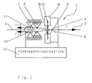
- Figure 1 shows schematically a yarn brake 1, as it can be used for example for braking a weft thread in a loom.
- the Faden.2 is guided in the direction 3 by the yarn brake.
- the braking force B is generated by two actuating elements 8, 9 and introduced into the yarn 2 via two brake sheets 4, 5 receiving the yarn 2 between them.
- the brake plates 4, 5 are opposite each other and are preferably resilient, wherein they are mounted in corresponding bearings 6, 7. When the thread brake is open, the thread 2 runs unhindered, without contact with the brake plates 4, 5 and without deflection through the thread brake through.
- a thread tension F is generated in the thread, which generates in the brake plates 4, 5 each acting in the running direction 3 of the thread counterforce of F / 2.
- the brake plates 4, 5 are movably mounted in the direction 3 of the thread 2 and mechanically coupled with stationary force sensors 10, 11.
- the respective force F / 2 acting on the brake plates 4, 5 is proportional to the thread tension force F and is measured by the load cells 10, 11 and fed to a control device.
- the measured force F is independent of the thread diameter and the friction coefficient of the thread 2 and the brake elements. However, it is directly proportional to the force exerted on the thread braking force B, and thus proportional to the thread tension.
- the control device 12 regulates the thread tension by changing the braking force B of the actuating elements 8, 9 as a function of the measured force F such that a desired thread tension is set in the thread 2.
- Figure 2 shows an embodiment of a yarn brake 1 with a passive brake plate 13 with adjustable bias, which is accommodated in a stationary bearing 13.
- the applied by an actuator 15 braking force B is transmitted to a brake plate 16 which bears against the brake plate 13, wherein the thread 2 between the brake plate 13 and the brake plate 16 is guided therethrough.
- the thread tensioning force F generated in the thread is equally transmitted to the brake plate 13 and the brake plate 16 and generates here in each case a counterforce F / 2 measured by a mechanically coupled to the brake plate 16 force transducer 17 and a control device 18 is supplied.
- the control device 18 regulates the thread tension by changing the braking force B of the actuating element 15 as a function of the measured force F such that a desired thread tension is set in the thread 2.
Landscapes
- Engineering & Computer Science (AREA)
- Textile Engineering (AREA)
- Looms (AREA)
- Tension Adjustment In Filamentary Materials (AREA)
Description
- Die Erfindung betrifft eine Vorrichtung und ein Verfahren zur Regelung der Fadenspannung eines Fadens bei Textilverarbeitungsmaschinen, insbesondere bei Webmaschinen, gemäß dem Oberbegriff der unabhängigen Patentansprüche.
- Derartige, oft auch als Fadenbremse bezeichnete Vorrichtungen, sind in vielfältigen Ausführungen bekannt und werden z.B. als Schussfadenbremse in Webmaschinen eingesetzt.
- Die DE 34 46 567 C1 zeigt eine Schussfadenbremse mit steuerbarer Bremswirkung, die aus zwei federnd gegeneinander liegenden, den Schussfaden zwischen sich aufnehmenden lamellenartigen Teilen besteht. Es sind elektromagnetisch steuerbare Mittel vorgesehen, die auf mindestens eines der lamellenartigen Teile einwirken und dadurch eine einstellbare Bremskraft auf den Faden ausüben.
- Eine ähnliche Ausführung einer Schussfadenbremse ist aus der DE 43 06 911 C1 vorbekannt. Dieser Schussfadenbremse liegt ebenfalls ein lamellenartiger Aufbau zugrunde, wobei die Lage mindestens einer der Lamellen durch einen Schrittmotor veränderbar ist, der über ein exzentrisch auf der Motorwelle angeordnetes Stellelement auf die Lamelle einwirkt.
- Es sind eine Vielzahl anderer Arten von Fadenbremsen bekannt, z.B. mit einem Bremsband und einem steuerbaren Bremskörper, zwischen welchen der Schussfaden geführt wird gemäß EP 0 475 892 A1, oder sogenannte Umschlingungsbremsen, bei denen die Bremskraft durch Änderung des Umschlingungswinkels einstellbar ist, vom Grundprinzip her anhand einer Fadenspannvorrichtung in der EP 0 467 059 A1 beschrieben.
- Bei allen bekannten Lösungen besteht die Fadenbremse im wesentlichen aus einem Fadenspannungssensor und der eigentlichen Fadenbremse. Am Fadenspannungssensor muss der Faden für eine Messung der aktuellen Fadenspannung bzw. der anliegenden Bremskraft umgelenkt werden, wodurch eine der Fadenspannung proportionale Kraft auf ein entsprechendes Messelement übertragen werden kann. Durch die Umlenkung ergibt sich aber eine unnötige mechanische Beanspruchung des Fadens, auch dann, wenn die Fadenbremse nicht arbeitet, d.h. geöffnet ist. In der US 5 842 661 A wird der Faden zwar nicht umgelenkt, da eine zur Fadenlaufrichtung senkrechte Kraft direkt an der Fadenbremse gemessen wird. Hierdurch ist aber keine Messung der Fadenspannung möglich.
- Die Aufgabe der Erfindung ist es daher, eine Vorrichtung und ein Verfahren zur Regelung der Fadenspannung eines Fadens bei Textilverarbeitungsmaschinen derart weiterzubilden, dass die mechanische Beanspruchung des Fadens minimiert wird.
- Die Aufgabe wird erfindungsgemäß durch die Merkmale der unabhängigen Patentansprüche gelöst.
- Danach umfasst die Fadenbremse erfindungsgemäß mindestens einen mit dem Bremselement mechanisch gekoppelten Kraftaufnehmer zur Messung einer vom Faden auf das Bremselement ausgeübten, in Laufrichtung des Fadens gerichteten und zur Fadenspannung proportionalen Kraft F, und eine Regelungseinrichtung zur Regelung der Fadenspannung durch Verändern der Bremskraft B in Abhängigkeit der gemessenen Kraft F.
- Das neuartige Prinzip der gesteuerten Fadenbremse beruht darauf, dass die Fadenspannung durch das Bremselemente erzeugt und gleichzeitig direkt am Bremselement gemessen wird, so dass die auf den Faden ausgeübte Bremskraft des Bremselements in Abhängigkeit der Fadenspannung geregelt werden kann.
- Die Fadenspannung wird gleichzeitig überwacht und geregelt. Bei bisherigen Lösungen musste der Faden für die Spannungsmessung umgelenkt werden. Bei der vorliegenden, neuartigen Lösung kann der Faden vollkommen frei durch die geöffnete Bremse hindurchgeführt werden. Der Faden muss für die Fadenspannungsmessung und Bremsung nicht umgelenkt werden, d.h. der Schussfaden kann absolut geradlinig durch die Fadenbremse geführt werden.
- Gemäß einer bevorzugten Ausgestaltung der Erfindung umfasst das Bremselement zwei sich gegenüberliegende und den Faden zwischen sich aufnehmende Kraftübertragungsmittel, wobei auf wenigstens eines der Kraftübertragungsmittel ein steuerbares Betätigungselement einwirkt, das die Lage wenigstens eines der Kraftübertragungsmittel gegenüber dem anderen verstellt.
- Mindestens eines der Kraftübertragungsmittel ist in Laufrichtung des Fadens linear beweglich gelagert und wirkt auf den Kraftaufnehmer, der vorzugsweise als piezoelektrischer Kraftaufnehmer ausgebildet ist.
- Gleichermaßen kann das Betätigungselement ein piezoelektrisches Stellelement sein, das sehr schnelle Stellbewegungen erlaubt.
- Die Erfindung wird nachfolgend anhand von zwei Ausführungsbeispielen näher beschrieben.
Es zeigen: - Figur 1:
- eine vereinfachte Darstellung einer ersten Ausführungsform der geregelten Fadenbremse;
- Figur 2:
- eine vereinfachte Darstellung einer zweiten Ausführungsform der geregelten Fadenbremse.
- Figur 1 zeigt schematisch eine Fadenbremse 1, wie sie z.B. zum Abbremsen eines Schussfadens in einer Webmaschine verwendet werden kann. Der Faden.2 wird in Laufrichtung 3 durch die Fadenbremse geführt. Die Bremskraft B wird von zwei Betätigungselementen 8, 9 erzeugt und über zwei den Faden 2 zwischen sich aufnehmende Bremsbleche 4, 5 in den Faden 2 eingeleitet. Die Bremsbleche 4, 5 liegen sich gegenüber und sind vorzugsweise federelastisch ausgebildet, wobei sie in entsprechenden Lagerungen 6, 7, gelagert sind.
Bei geöffneter Fadenbremse läuft der Faden 2 ungehindert, ohne Kontakt zu den Bremsblechen 4, 5 und ohne Umlenkung durch die Fadenbremse hindurch. - Durch Aufbringen einer Bremskraft B auf den Faden 2 wird eine Fadenspannungskraft F im Faden erzeugt, welche in den Bremsblechen 4, 5 jeweils eine in Laufrichtung 3 des Fadens wirkende Gegenkraft von F/2 erzeugt. Die Bremsbleche 4, 5 sind in Laufrichtung 3 des Fadens 2 beweglich gelagert und mechanisch mit ortsfesten Kraftaufnehmern 10, 11 gekoppelt. Die jeweils auf die Bremsbleche 4, 5 wirkende Gegenkraft F/2 ist proportional zur Fadenspannungskraft F und wird von den Kraftaufnehmern 10, 11 gemessen und einer Regelungseinrichtung zugeführt.
- Die gemessene Kraft F ist unabhängig vom Fadendurchmesser und dem Reibbeiwert des Fadens 2 und der Bremselemente. Sie ist jedoch direkt proportional zu der auf den Faden ausgeübten Bremskraft B, und somit proportional zur Fadenspannung.
- Die Regelungseinrichtung 12 regelt die Fadenspannung durch Verändern der Bremskraft B der Betätigungselemente 8, 9 in Abhängigkeit der gemessenen Kraft F derart, dass sich eine gewünschte Fadenspannung im Faden 2 einstellt.
- Figur 2 zeigt eine Ausgestaltung einer Fadenbremse 1 mit einem passiven Bremsblech 13 mit einstellbarer Vorspannung, das in einer ortsfesten Lagerung 13 aufgenommen ist.
Die von einem Betätigungselement 15 aufgebrachte Bremskraft B wird auf eine Bremsplatte 16 übertragen, die am Bremsblech 13 anliegt, wobei der Faden 2 zwischen Bremsblech 13 und Bremsplatte 16 hindurch geführt ist.
Die im Faden erzeugte Fadenspannungskraft F überträgt sich gleichermaßen auf das Bremsblech 13 und die Bremsplatte 16 und erzeugt hier jeweils eine Gegenkraft F/2 die von einem mit der Bremsplatte 16 mechanisch gekoppelten Kraftaufnehmer 17 gemessen und einer Regelungseinrichtung 18 zugeführt wird. - Die Regelungseinrichtung 18 regelt die Fadenspannung durch Verändern der Bremskraft B des Betätigungselementes 15 in Abhängigkeit der gemessenen Kraft F derart, dass sich eine gewünschte Fadenspannung im Faden 2 einstellt.
-
- 1
- Fadenbremse
- 2
- Faden
- 3
- Laufrichtung
- 4
- Bremsblech
- 5
- Bremsblech
- 6
- Lagerung
- 7
- Lagerung
- 8
- Betätigungselement
- 9
- Betätigungselement
- 10
- Kraftaufnehmer
- 11
- Kraftaufnehmer
- 12
- Regelungseinrichtung
- 13
- Bremsblech
- 14
- Lagerung
- 15
- Betätigungselement
- 16
- Bremsplatte
- 17
- Kraftaufnehmer
- 18
- Regelungseinrichtung
Claims (7)
- Vorrichtung zur Regelung der Fadenspannung eines Fadens bei Textilverarbeitungsmaschinen, mit mindestens einem auf den Faden wirkenden Bremselement zur Ausübung einer einstellbaren Bremskraft B auf den Faden, gekennzeichnet durch
mindestens einen mit dem Bremselement mechanisch gekoppelten Kraftaufnehmer (10; 11; 17) zur Messung einer vom Faden (2) auf das Bremselement wirkenden, in Laufrichtung (3) des Fadens gerichteten und zur Fadenspannung proportionalen Kraft F, und
eine Regelungseinrichtung (12) zur Regelung der Fadenspannung durch Verändern der Bremskraft B in Abhängigkeit der gemessenen Kraft F,
wobei der Faden geradlinig durch die Vorrichtung geführt wird. - Vorrichtung nach Anspruch 1, dadurch gekennzeichnet, dass das Bremselement zwei sich gegenüberliegende und den Faden zwischen sich aufnehmende Kraftübertragungsmittel (4, 5; 13, 16) umfasst, wobei auf wenigstens eines der Kraftübertragungsmittel (4; 5; 16) ein steuerbares Betätigungselement (8; 9; 15) einwirkt, das die Lage wenigstens eines der Kraftübertragungsmittel gegenüber dem anderen verstellt.
- Vorrichtung nach Anspruch 1 oder 2, dadurch gekennzeichnet, dass mindestens eines der Kraftübertragungsmittel (4; 5; 16) in Laufrichtung (3) des Fadens (2) beweglich gelagert ist.
- Vorrichtung nach einem der Ansprüche 1 bis 3, dadurch gekennzeichnet, dass der Kraftaufnehmer (10; 11; 17) ein piezoelektrischer Kraftaufnehmer ist.
- Vorrichtung nach einem der Ansprüche 1 bis 4, dadurch gekennzeichnet, dass das Betätigungselement (8; 9; 15) ein piezoelektrisches Stellelement ist.
- Verfahren zur Regelung der Fadenspannung eines Fadens bei Textilverarbeitungsmaschinen, bei dem mittels eines auf den Faden wirkenden Bremselements eine Bremskraft B auf den Faden ausgeübt wird,
dadurch gekennzeichnet,
dass mittels eines Kraftaufnehmers (10; 11; 17) eine vom Faden (2) auf das Bremselement wirkende, in Laufrichtung (3) des Fadens gerichtete und zur Fadenspannung proportionale Kraft F gemessen wird, und die Fadenspannung durch Verändern der Bremskraft B in Abhängigkeit der gemessenen Kraft F geregelt wird, wobei der Faden für die Fadenspannungsmessung und Bremsung nicht umgelenkt wird. - Verfahren nach Anspruch 6, dadurch gekennzeichnet, dass der Faden (2) bei geöffnetem Bremselement ungehindert und ohne Berührung und Umlenkung durch das Bremselement geführt ist.
Applications Claiming Priority (2)
| Application Number | Priority Date | Filing Date | Title |
|---|---|---|---|
| DE10218059 | 2002-04-23 | ||
| DE10218059A DE10218059A1 (de) | 2002-04-23 | 2002-04-23 | Vorrichtung und Verfahren zur Regelung der Fadenspannung eines Fadens bei Textilverarbeitungsmaschinen |
Publications (3)
| Publication Number | Publication Date |
|---|---|
| EP1357213A2 EP1357213A2 (de) | 2003-10-29 |
| EP1357213A3 EP1357213A3 (de) | 2004-02-11 |
| EP1357213B1 true EP1357213B1 (de) | 2006-10-18 |
Family
ID=28685249
Family Applications (1)
| Application Number | Title | Priority Date | Filing Date |
|---|---|---|---|
| EP03004706A Expired - Lifetime EP1357213B1 (de) | 2002-04-23 | 2003-03-04 | Vorrichtung und Verfahren zur Regelung der Fadenspannung eines Fadens bei Textilverarbeitungsmaschinen |
Country Status (5)
| Country | Link |
|---|---|
| US (1) | US7077168B2 (de) |
| EP (1) | EP1357213B1 (de) |
| JP (1) | JP3977276B2 (de) |
| AT (1) | ATE343008T1 (de) |
| DE (2) | DE10218059A1 (de) |
Families Citing this family (6)
| Publication number | Priority date | Publication date | Assignee | Title |
|---|---|---|---|---|
| US7543610B2 (en) * | 2006-06-16 | 2009-06-09 | Sultex Ag | Thread clamp for a rapier head |
| EP1961686B1 (de) * | 2007-02-20 | 2016-09-14 | Iro Ab | System zur Überwachung und Einstellung einer Garnspannung |
| WO2009025803A1 (en) | 2007-08-20 | 2009-02-26 | Kevin Kremeyer | Energy-deposition systems, equipment and methods for modifying and controlling shock waves and supersonic flow |
| DE102013222679A1 (de) * | 2013-11-07 | 2015-05-07 | Lindauer Dornier Gesellschaft Mit Beschränkter Haftung | Verfahren zum Messen der Gewebespannung in einer Webmaschine |
| US10669653B2 (en) * | 2015-06-18 | 2020-06-02 | Kevin Kremeyer | Directed energy deposition to facilitate high speed applications |
| ITUB20155266A1 (it) * | 2015-10-30 | 2016-01-30 | Roj S R L | Freno elettromagnetico pilotato per il controllo della tensione dei fili di trama in macchine tessili |
Family Cites Families (14)
| Publication number | Priority date | Publication date | Assignee | Title |
|---|---|---|---|---|
| DE3446567C1 (de) * | 1984-12-20 | 1986-05-07 | Lindauer Dornier Gmbh, 8990 Lindau | Schussfadenbremse mit stufenweise steuerbarer Bremswirkung |
| DE3637919A1 (de) * | 1986-11-06 | 1988-05-19 | Dornier Gmbh Lindauer | Schussfadenbremse mit steuerbarer bremswirkung fuer schuetzenlose webmaschinen |
| SE468519B (sv) * | 1987-05-27 | 1993-02-01 | Rydborn S A O | Traadsignalgivare vid traadbroms |
| JPH02200834A (ja) * | 1989-01-31 | 1990-08-09 | Baba Sangyo Kikai Kk | 整経機の張力制御装置 |
| IT1248716B (it) | 1990-06-11 | 1995-01-26 | Vamatex Spa | Dispositivo per la regolazione della tensione ed il recupero del filo di trama in telai di tessitura |
| EP0475892B1 (de) | 1990-09-10 | 1995-05-17 | Sulzer RàTi Ag | Fadenbremse für Webmaschinen |
| DE4129803A1 (de) * | 1991-09-07 | 1993-03-11 | Schlafhorst & Co W | Fadenzugkraftsensor fuer eine textilmaschine |
| DE4306911C1 (de) * | 1993-03-05 | 1993-12-23 | Dornier Gmbh Lindauer | Schußfadenbremse mit steuerbarer Bremswirkung |
| US5476122A (en) * | 1993-03-05 | 1995-12-19 | Lindauer Dornier Gesellschaft Mbh | Weft thread brake responsive to yarn characteristics in a loom |
| DE19535895C1 (de) * | 1995-09-27 | 1996-06-13 | Dornier Gmbh Lindauer | Einrichtung zum Reduzieren der Belastung eines in das Webfach einer Webmaschine einzutragenden Schußfadens |
| DE19544202B4 (de) * | 1995-11-28 | 2007-01-04 | Saurer Gmbh & Co. Kg | Verfahren und Vorrichtung zum Einregeln einer nach einem Rechenspanner vorliegenden Fadenzugkraft in einer Textilmaschine |
| DE19633256C1 (de) * | 1996-08-17 | 1997-10-09 | Mayer Textilmaschf | Vorrichtung zum Einstellen der Zugspannung eines Fadens bei dessen Ab- oder Aufwicklung von einer bzw. auf eine Spule |
| DE29909242U1 (de) * | 1999-05-27 | 1999-09-16 | Lindauer Dornier Gmbh, 88131 Lindau | Schussfadenbremse für Webmaschinen |
| DE10013625A1 (de) * | 2000-03-18 | 2001-09-27 | Dornier Gmbh Lindauer | Fadenbremse, insbesondere Schussfadenbremse für Webmaschinen |
-
2002
- 2002-04-23 DE DE10218059A patent/DE10218059A1/de not_active Ceased
-
2003
- 2003-03-04 DE DE50305395T patent/DE50305395D1/de not_active Expired - Lifetime
- 2003-03-04 EP EP03004706A patent/EP1357213B1/de not_active Expired - Lifetime
- 2003-03-04 AT AT03004706T patent/ATE343008T1/de not_active IP Right Cessation
- 2003-04-09 JP JP2003104872A patent/JP3977276B2/ja not_active Expired - Fee Related
- 2003-04-23 US US10/422,042 patent/US7077168B2/en not_active Expired - Fee Related
Also Published As
| Publication number | Publication date |
|---|---|
| JP2003313750A (ja) | 2003-11-06 |
| EP1357213A2 (de) | 2003-10-29 |
| US7077168B2 (en) | 2006-07-18 |
| DE10218059A1 (de) | 2003-11-13 |
| JP3977276B2 (ja) | 2007-09-19 |
| ATE343008T1 (de) | 2006-11-15 |
| DE50305395D1 (de) | 2006-11-30 |
| US20030196718A1 (en) | 2003-10-23 |
| EP1357213A3 (de) | 2004-02-11 |
Similar Documents
| Publication | Publication Date | Title |
|---|---|---|
| EP0829720B1 (de) | Vorrichtung zur Messung der Biegesteifigkeit von bewegtem blattförmigem Material | |
| DE2232983A1 (de) | Vorrichtung zum messen der spannung einer laufenden materialbahn, eines drahtes oder dergl | |
| DE2320369A1 (de) | Vorrichtung zum feststellen von dickeunterschieden in stapelfaserbaendern | |
| DE60017693T2 (de) | Verfahren und Vorrichtung zur Steuerung von elektrisch gesteuerter Schussfadenbremsen zur automatischen Einstellung der mechanischen Spannung eines Schussfadens in Textilmaschinen mit mechanischem Schusseintrag | |
| DE19633256C1 (de) | Vorrichtung zum Einstellen der Zugspannung eines Fadens bei dessen Ab- oder Aufwicklung von einer bzw. auf eine Spule | |
| DE3608182C2 (de) | ||
| EP0608001B1 (de) | Ringspinnmaschine mit einem Fadenspannungssensor sowie Anwendung eines Fadenspannungssensors zur Steuerung einer Ringspinnmaschine | |
| DE3635341A1 (de) | Vorrichtung zur regulierung des verzugs eines faserbands bei einer textilmaschine | |
| EP1157263A1 (de) | Bragg-gitter-vorrichtung zum messen einer mechanischen kraft sowie anwendung und verfahren zum betrieb der vorrichtung | |
| DE10231742B3 (de) | Vorrichtung zum Bearbeiten einer Materialbahn, Verfahren zum Steuern und Ermitteln der Lage und/oder der Anpresskraft einer Sonotrode sowie Verfahren zur Überwachung der in einem Bearbeitungsspalt bewegten Materialbahn | |
| DE10218059A1 (de) | Vorrichtung und Verfahren zur Regelung der Fadenspannung eines Fadens bei Textilverarbeitungsmaschinen | |
| EP0491151A1 (de) | Kraftmessvorrichtung zur Messung der Zugspannung von Fäden | |
| EP1056568B1 (de) | Verfahren zum anziehen von verschraubungen | |
| EP0973686A1 (de) | Fadenbremse | |
| EP0686838B1 (de) | Vorrichtung zum Messen der Fadenspannung und Webmaschine | |
| EP0417232B1 (de) | Bahnlaufregler | |
| DE19538423C2 (de) | Vorrichtung zum Kräuseln von synthetischen Fadenbündeln oder -bändern | |
| EP2253567A2 (de) | Vorrichtung zum kontinuierlichen Aufwickeln einer Faserstoffbahn | |
| WO1998012719A1 (de) | Vorrichtung zur regelung der zugkraft eines spulenwickeldrahtes | |
| DE4041142A1 (de) | Vorrichtung zur ermittlung der fadenspannung | |
| EP0560337A2 (de) | Verfahren und Vorrichtung zur Steck- und Ziehkraftmessung an Steckkontakten | |
| DE4025005A1 (de) | Maschine zum herstellen von kreuzspulen, mit einrichtungen zum steuern der spulstellen nach der fadenspannung | |
| DE19509485C1 (de) | Schwingungsisolator | |
| DE102006033699A1 (de) | Drahtsäge mit kontrollierbarem Drahtfeld | |
| EP3767019B1 (de) | Sensor-anordnung zum erfassen zumindest einer physikalischen kenngrösse einer vielzahl von fäden |
Legal Events
| Date | Code | Title | Description |
|---|---|---|---|
| PUAI | Public reference made under article 153(3) epc to a published international application that has entered the european phase |
Free format text: ORIGINAL CODE: 0009012 |
|
| AK | Designated contracting states |
Kind code of ref document: A2 Designated state(s): AT BE BG CH CY CZ DE DK EE ES FI FR GB GR HU IE IT LI LU MC NL PT SE SI SK TR |
|
| AX | Request for extension of the european patent |
Extension state: AL LT LV MK RO |
|
| PUAL | Search report despatched |
Free format text: ORIGINAL CODE: 0009013 |
|
| AK | Designated contracting states |
Kind code of ref document: A3 Designated state(s): AT BE BG CH CY CZ DE DK EE ES FI FR GB GR HU IE IT LI LU MC NL PT SE SI SK TR |
|
| AX | Request for extension of the european patent |
Extension state: AL LT LV MK RO |
|
| RIC1 | Information provided on ipc code assigned before grant |
Ipc: 7D 03D 47/34 A Ipc: 7B 65H 59/24 B |
|
| 17P | Request for examination filed |
Effective date: 20040519 |
|
| AKX | Designation fees paid |
Designated state(s): AT BE BG CH CY CZ DE DK EE ES FI FR GB GR HU IE IT LI LU MC NL PT SE SI SK TR |
|
| GRAP | Despatch of communication of intention to grant a patent |
Free format text: ORIGINAL CODE: EPIDOSNIGR1 |
|
| GRAS | Grant fee paid |
Free format text: ORIGINAL CODE: EPIDOSNIGR3 |
|
| RBV | Designated contracting states (corrected) |
Designated state(s): AT BE BG CH CY CZ DE DK EE ES FI FR GB GR HU IE IT LI LU MC NL PT RO SE SI SK TR |
|
| GRAA | (expected) grant |
Free format text: ORIGINAL CODE: 0009210 |
|
| AK | Designated contracting states |
Kind code of ref document: B1 Designated state(s): AT BE BG CH CY CZ DE DK EE ES FI FR GB GR HU IE IT LI LU MC NL PT RO SE SI SK TR |
|
| PG25 | Lapsed in a contracting state [announced via postgrant information from national office to epo] |
Ref country code: SI Free format text: LAPSE BECAUSE OF FAILURE TO SUBMIT A TRANSLATION OF THE DESCRIPTION OR TO PAY THE FEE WITHIN THE PRESCRIBED TIME-LIMIT Effective date: 20061018 Ref country code: FI Free format text: LAPSE BECAUSE OF FAILURE TO SUBMIT A TRANSLATION OF THE DESCRIPTION OR TO PAY THE FEE WITHIN THE PRESCRIBED TIME-LIMIT Effective date: 20061018 Ref country code: IE Free format text: LAPSE BECAUSE OF FAILURE TO SUBMIT A TRANSLATION OF THE DESCRIPTION OR TO PAY THE FEE WITHIN THE PRESCRIBED TIME-LIMIT Effective date: 20061018 Ref country code: RO Free format text: LAPSE BECAUSE OF FAILURE TO SUBMIT A TRANSLATION OF THE DESCRIPTION OR TO PAY THE FEE WITHIN THE PRESCRIBED TIME-LIMIT Effective date: 20061018 Ref country code: NL Free format text: LAPSE BECAUSE OF FAILURE TO SUBMIT A TRANSLATION OF THE DESCRIPTION OR TO PAY THE FEE WITHIN THE PRESCRIBED TIME-LIMIT Effective date: 20061018 Ref country code: SK Free format text: LAPSE BECAUSE OF FAILURE TO SUBMIT A TRANSLATION OF THE DESCRIPTION OR TO PAY THE FEE WITHIN THE PRESCRIBED TIME-LIMIT Effective date: 20061018 Ref country code: CZ Free format text: LAPSE BECAUSE OF FAILURE TO SUBMIT A TRANSLATION OF THE DESCRIPTION OR TO PAY THE FEE WITHIN THE PRESCRIBED TIME-LIMIT Effective date: 20061018 |
|
| REG | Reference to a national code |
Ref country code: GB Ref legal event code: FG4D Free format text: NOT ENGLISH |
|
| REG | Reference to a national code |
Ref country code: CH Ref legal event code: EP Ref country code: IE Ref legal event code: FG4D Free format text: LANGUAGE OF EP DOCUMENT: GERMAN |
|
| REF | Corresponds to: |
Ref document number: 50305395 Country of ref document: DE Date of ref document: 20061130 Kind code of ref document: P |
|
| REG | Reference to a national code |
Ref country code: SE Ref legal event code: TRGR |
|
| PG25 | Lapsed in a contracting state [announced via postgrant information from national office to epo] |
Ref country code: DK Free format text: LAPSE BECAUSE OF FAILURE TO SUBMIT A TRANSLATION OF THE DESCRIPTION OR TO PAY THE FEE WITHIN THE PRESCRIBED TIME-LIMIT Effective date: 20070118 Ref country code: BG Free format text: LAPSE BECAUSE OF FAILURE TO SUBMIT A TRANSLATION OF THE DESCRIPTION OR TO PAY THE FEE WITHIN THE PRESCRIBED TIME-LIMIT Effective date: 20070118 |
|
| PG25 | Lapsed in a contracting state [announced via postgrant information from national office to epo] |
Ref country code: ES Free format text: LAPSE BECAUSE OF FAILURE TO SUBMIT A TRANSLATION OF THE DESCRIPTION OR TO PAY THE FEE WITHIN THE PRESCRIBED TIME-LIMIT Effective date: 20070129 |
|
| REG | Reference to a national code |
Ref country code: CH Ref legal event code: NV Representative=s name: R. A. EGLI & CO. PATENTANWAELTE |
|
| PG25 | Lapsed in a contracting state [announced via postgrant information from national office to epo] |
Ref country code: PT Free format text: LAPSE BECAUSE OF FAILURE TO SUBMIT A TRANSLATION OF THE DESCRIPTION OR TO PAY THE FEE WITHIN THE PRESCRIBED TIME-LIMIT Effective date: 20070319 |
|
| NLV1 | Nl: lapsed or annulled due to failure to fulfill the requirements of art. 29p and 29m of the patents act | ||
| GBV | Gb: ep patent (uk) treated as always having been void in accordance with gb section 77(7)/1977 [no translation filed] |
Effective date: 20061018 |
|
| EN | Fr: translation not filed | ||
| REG | Reference to a national code |
Ref country code: IE Ref legal event code: FD4D |
|
| PLBE | No opposition filed within time limit |
Free format text: ORIGINAL CODE: 0009261 |
|
| STAA | Information on the status of an ep patent application or granted ep patent |
Free format text: STATUS: NO OPPOSITION FILED WITHIN TIME LIMIT |
|
| 26N | No opposition filed |
Effective date: 20070719 |
|
| PG25 | Lapsed in a contracting state [announced via postgrant information from national office to epo] |
Ref country code: GB Free format text: LAPSE BECAUSE OF FAILURE TO SUBMIT A TRANSLATION OF THE DESCRIPTION OR TO PAY THE FEE WITHIN THE PRESCRIBED TIME-LIMIT Effective date: 20061018 |
|
| PG25 | Lapsed in a contracting state [announced via postgrant information from national office to epo] |
Ref country code: MC Free format text: LAPSE BECAUSE OF NON-PAYMENT OF DUE FEES Effective date: 20070331 |
|
| PG25 | Lapsed in a contracting state [announced via postgrant information from national office to epo] |
Ref country code: GR Free format text: LAPSE BECAUSE OF FAILURE TO SUBMIT A TRANSLATION OF THE DESCRIPTION OR TO PAY THE FEE WITHIN THE PRESCRIBED TIME-LIMIT Effective date: 20070119 Ref country code: FR Free format text: LAPSE BECAUSE OF FAILURE TO SUBMIT A TRANSLATION OF THE DESCRIPTION OR TO PAY THE FEE WITHIN THE PRESCRIBED TIME-LIMIT Effective date: 20070601 |
|
| PG25 | Lapsed in a contracting state [announced via postgrant information from national office to epo] |
Ref country code: AT Free format text: LAPSE BECAUSE OF NON-PAYMENT OF DUE FEES Effective date: 20070304 |
|
| PG25 | Lapsed in a contracting state [announced via postgrant information from national office to epo] |
Ref country code: FR Free format text: LAPSE BECAUSE OF FAILURE TO SUBMIT A TRANSLATION OF THE DESCRIPTION OR TO PAY THE FEE WITHIN THE PRESCRIBED TIME-LIMIT Effective date: 20061018 |
|
| PG25 | Lapsed in a contracting state [announced via postgrant information from national office to epo] |
Ref country code: EE Free format text: LAPSE BECAUSE OF FAILURE TO SUBMIT A TRANSLATION OF THE DESCRIPTION OR TO PAY THE FEE WITHIN THE PRESCRIBED TIME-LIMIT Effective date: 20061018 |
|
| PG25 | Lapsed in a contracting state [announced via postgrant information from national office to epo] |
Ref country code: CY Free format text: LAPSE BECAUSE OF FAILURE TO SUBMIT A TRANSLATION OF THE DESCRIPTION OR TO PAY THE FEE WITHIN THE PRESCRIBED TIME-LIMIT Effective date: 20061018 Ref country code: LU Free format text: LAPSE BECAUSE OF NON-PAYMENT OF DUE FEES Effective date: 20070304 |
|
| PG25 | Lapsed in a contracting state [announced via postgrant information from national office to epo] |
Ref country code: TR Free format text: LAPSE BECAUSE OF FAILURE TO SUBMIT A TRANSLATION OF THE DESCRIPTION OR TO PAY THE FEE WITHIN THE PRESCRIBED TIME-LIMIT Effective date: 20061018 Ref country code: HU Free format text: LAPSE BECAUSE OF FAILURE TO SUBMIT A TRANSLATION OF THE DESCRIPTION OR TO PAY THE FEE WITHIN THE PRESCRIBED TIME-LIMIT Effective date: 20070419 |
|
| PGFP | Annual fee paid to national office [announced via postgrant information from national office to epo] |
Ref country code: SE Payment date: 20091222 Year of fee payment: 8 |
|
| PGFP | Annual fee paid to national office [announced via postgrant information from national office to epo] |
Ref country code: CH Payment date: 20100325 Year of fee payment: 8 |
|
| PGFP | Annual fee paid to national office [announced via postgrant information from national office to epo] |
Ref country code: IT Payment date: 20100326 Year of fee payment: 8 |
|
| PGFP | Annual fee paid to national office [announced via postgrant information from national office to epo] |
Ref country code: BE Payment date: 20100323 Year of fee payment: 8 Ref country code: DE Payment date: 20100521 Year of fee payment: 8 |
|
| BERE | Be: lapsed |
Owner name: LINDAUER DORNIER G.M.B.H. Effective date: 20110331 |
|
| REG | Reference to a national code |
Ref country code: CH Ref legal event code: PL |
|
| REG | Reference to a national code |
Ref country code: SE Ref legal event code: EUG |
|
| PG25 | Lapsed in a contracting state [announced via postgrant information from national office to epo] |
Ref country code: BE Free format text: LAPSE BECAUSE OF NON-PAYMENT OF DUE FEES Effective date: 20110331 |
|
| PG25 | Lapsed in a contracting state [announced via postgrant information from national office to epo] |
Ref country code: CH Free format text: LAPSE BECAUSE OF NON-PAYMENT OF DUE FEES Effective date: 20110331 Ref country code: DE Free format text: LAPSE BECAUSE OF NON-PAYMENT OF DUE FEES Effective date: 20111001 Ref country code: LI Free format text: LAPSE BECAUSE OF NON-PAYMENT OF DUE FEES Effective date: 20110331 |
|
| REG | Reference to a national code |
Ref country code: DE Ref legal event code: R119 Ref document number: 50305395 Country of ref document: DE Effective date: 20111001 |
|
| PG25 | Lapsed in a contracting state [announced via postgrant information from national office to epo] |
Ref country code: IT Free format text: LAPSE BECAUSE OF NON-PAYMENT OF DUE FEES Effective date: 20110304 |
|
| PG25 | Lapsed in a contracting state [announced via postgrant information from national office to epo] |
Ref country code: SE Free format text: LAPSE BECAUSE OF NON-PAYMENT OF DUE FEES Effective date: 20110305 |