US20030196718A1 - Thread tension regulation in a thread brake device and method in a textile processing machine - Google Patents
Thread tension regulation in a thread brake device and method in a textile processing machine Download PDFInfo
- Publication number
- US20030196718A1 US20030196718A1 US10/422,042 US42204203A US2003196718A1 US 20030196718 A1 US20030196718 A1 US 20030196718A1 US 42204203 A US42204203 A US 42204203A US 2003196718 A1 US2003196718 A1 US 2003196718A1
- Authority
- US
- United States
- Prior art keywords
- thread
- brake element
- force
- thread brake
- brake
- Prior art date
- Legal status (The legal status is an assumption and is not a legal conclusion. Google has not performed a legal analysis and makes no representation as to the accuracy of the status listed.)
- Granted
Links
Images


Classifications
-
- D—TEXTILES; PAPER
- D03—WEAVING
- D03D—WOVEN FABRICS; METHODS OF WEAVING; LOOMS
- D03D47/00—Looms in which bulk supply of weft does not pass through shed, e.g. shuttleless looms, gripper shuttle looms, dummy shuttle looms
- D03D47/34—Handling the weft between bulk storage and weft-inserting means
-
- B—PERFORMING OPERATIONS; TRANSPORTING
- B65—CONVEYING; PACKING; STORING; HANDLING THIN OR FILAMENTARY MATERIAL
- B65H—HANDLING THIN OR FILAMENTARY MATERIAL, e.g. SHEETS, WEBS, CABLES
- B65H59/00—Adjusting or controlling tension in filamentary material, e.g. for preventing snarling; Applications of tension indicators
- B65H59/10—Adjusting or controlling tension in filamentary material, e.g. for preventing snarling; Applications of tension indicators by devices acting on running material and not associated with supply or take-up devices
- B65H59/20—Co-operating surfaces mounted for relative movement
- B65H59/22—Co-operating surfaces mounted for relative movement and arranged to apply pressure to material
- B65H59/24—Surfaces movable automatically to compensate for variation in tension
-
- B—PERFORMING OPERATIONS; TRANSPORTING
- B65—CONVEYING; PACKING; STORING; HANDLING THIN OR FILAMENTARY MATERIAL
- B65H—HANDLING THIN OR FILAMENTARY MATERIAL, e.g. SHEETS, WEBS, CABLES
- B65H2515/00—Physical entities not provided for in groups B65H2511/00 or B65H2513/00
- B65H2515/30—Forces; Stresses
- B65H2515/31—Tensile forces
-
- B—PERFORMING OPERATIONS; TRANSPORTING
- B65—CONVEYING; PACKING; STORING; HANDLING THIN OR FILAMENTARY MATERIAL
- B65H—HANDLING THIN OR FILAMENTARY MATERIAL, e.g. SHEETS, WEBS, CABLES
- B65H2515/00—Physical entities not provided for in groups B65H2511/00 or B65H2513/00
- B65H2515/30—Forces; Stresses
- B65H2515/34—Pressure, e.g. fluid pressure
-
- B—PERFORMING OPERATIONS; TRANSPORTING
- B65—CONVEYING; PACKING; STORING; HANDLING THIN OR FILAMENTARY MATERIAL
- B65H—HANDLING THIN OR FILAMENTARY MATERIAL, e.g. SHEETS, WEBS, CABLES
- B65H2701/00—Handled material; Storage means
- B65H2701/30—Handled filamentary material
- B65H2701/31—Textiles threads or artificial strands of filaments
Definitions
- the invention relates to an apparatus and a method for regulating the thread tension in connection with selective braking of the thread in a textile processing machine, especially in a weaving loom.
- Such devices pertinent to the general background of the present invention often known as thread brakes, are well known in many different conventional configurations and arrangements, and are typically used, for example, as weft thread brakes in weaving looms.
- German Patent 34 46 567 and corresponding U.S. Pat. No. 4,641,688 disclose a weft thread brake with a controllable braking effect.
- This known weft thread brake comprises two lamellar brake elements that are arranged opposite each other and press against each other in a spring-elastic manner, with the weft thread received therebetween.
- the known thread brake arrangement further comprises at least one controllable electromagnetic actuator that selectively acts on and moves or applies a force to at least one of the lamellar brake elements relative to the other, and thereby causes an adjustable braking force to be applied to the thread passing between the two lamellar brake elements.
- a similar embodiment and construction of a weft thread brake is known from German Patent 43 06 911 and corresponding U.S. Pat. No. 5,398,731.
- the basic construction of this known thread brake also includes two lamellar brake elements that selectively or adjustably press against each other, with the weft thread passing therebetween.
- the position and force of at least one of the lamellar brake elements relative to the other is adjustable by means of a stepper motor, and an actuating cam element that is mounted eccentrically on the shaft of the stepper motor, so that the actuating cam variably acts on the lamellar brake elements due to the stepping rotation of the stepper motor.
- thread brakes A great number and variety of other types of thread brakes are generally known in the art of textile processing machines.
- some known thread brakes operate with a brake band and a controllable brake body, with the weft thread guided therebetween, for example according to European Patent 0,475,892.
- Another type of thread brake involves a so-called thread looping or wrapping brake, in which the thread is deflected, looped, or wrapped to a variable extent around a braking element, and the applied braking force is adjustable by changing the thread deflection or looping angle.
- the basic principle of such a brake arrangement is described in connection with the thread tensioning apparatus in European Patent Specification 0,467,059.
- the overall thread brake arrangement essentially consists of the actual thread break device itself together with an additional thread tension sensor.
- the thread tension is measured by an additional or separate thread tension sensor in order to then control the actuation of the thread brake in response to and dependent on the measured thread tension.
- the separate thread tension sensor requires the thread to be deflected around a suitable measuring element in order to be able to measure the actual presently existing thread tension, which is representative of or associated with the applied braking force. In this manner, a force proportional to the actual existing thread tension is exerted onto the suitable measuring element, which then provides a signal representative of the thread tension.
- the invention further aims to avoid or overcome the disadvantages of the prior art, and to achieve additional advantages, as apparent from the present specification.
- an apparatus for regulating the thread tension of a thread in a textile processing machine comprising at least one brake element that acts on the thread so as to apply an adjustable braking force to the thread, as well as a force pickup transducer mechanically coupled to the brake element for measuring a reaction force exerted by the thread onto the brake element.
- This reaction force is oriented in the running direction of the thread and is proportional to the thread tension.
- the inventive apparatus further comprises a regulating arrangement or control device for regulating the thread tension by selectively actuating the brake element to selectively vary or adjust the braking force responsive to and dependent on the measured reaction force.
- a method for regulating the thread tension of a thread in a textile processing machine comprising the following steps: applying a braking force to the thread with an adjustable thread brake element; exerting a reaction force, which is oriented in the running direction of the thread and proportional to the thread tension, from the thread onto the thread brake element; measuring or sensing the reaction force that is exerted on the thread brake element, using a force pickup transducer; and regulating the thread tension by varying or adjusting the braking force dependent on and responsive to the measured reaction force.
- the new basic principle for achieving a controlled thread braking effect according to the invention is that the thread tension is applied or caused by the brake element and is simultaneously measured directly on the brake element (via the reaction force or counter force that is exerted by the thread onto the brake element). In this manner, the braking force of the brake element applied to the thread can be regulated dependent on and responsive to the thread tension. The thread tension is measured directly by the reaction force exerted on the brake element by the thread, so that a separate thread tension sensor is no longer necessary.
- the thread tension is simultaneously monitored and regulated through the brake element or elements.
- the thread had to be deflected, for example around a thread tension sensor element, for carrying out the thread tension measurement.
- no additional thread tension sensor is needed, and the thread does not need to be deflected out of its linear thread travel path for achieving the thread tension measurement.
- the thread will be guided completely freely through the open brake arrangement, without any mechanical load or deflection being applied to the thread.
- the thread e.g. the weft thread, can be guided through the thread brake arrangement absolutely linearly without any deflection out of such a linear thread path for achieving both the thread tension measurement and the thread braking.
- the thread brake arrangement comprises two brake elements or force application elements that are arranged opposite one another and receive the thread passing therebetween.
- the two force application elements may be two lamellar brake elements, or two rigid brake plates or shoes, or one lamellar brake element and one rigid brake plate or shoe.
- a controllable actuating element acts on at least one of the force application elements, so as to vary or adjust the position and the pressing force of at least one of the force application elements relative to the other.
- At least one of the force application elements is supported so that it is movable, and preferably linearly movable, along or parallel to the running direction of the thread.
- a force pickup transducer is mechanically coupled to this movable force application element so as to sense force acting on this element and/or the motion of this element along or parallel to the thread running direction.
- This force pickup transducer is preferably embodied as a piezoelectric force transducer.
- the reaction force or drag force exerted by the thread onto the force application element or elements of the brake arrangement causes a corresponding motion of the force application element or elements in the running direction of the thread, and this motion is sensed by the force transducer, to provide a signal indicative of or especially proportional to the actual presently existing thread tension.
- the controllable actuator element acting on at least one of the force application elements may also preferably be embodied as a piezoelectric actuating element.
- a piezoelectric actuating element is able to carry out very rapid actuating motions.
- the selective variable application of the braking force onto the thread can be very rapidly adjusted dependent on and responsive to the reaction force that is measured in the above described manner.
- the inventive arrangement provides a very rapidly acting feedback loop of the force information, which allows a rapid regulation of the braking force and the resulting thread tension.
- FIG. 1 is a simplified schematic diagram of a first embodiment of a regulated thread brake arrangement according to the invention.
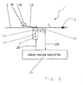
- FIG. 2 is a simplified schematic diagram of a second embodiment of a regulated thread brake arrangement according to the invention.
- FIG. 1 schematically shows a thread brake arrangement 1 according to the invention, as it may be used for braking a weft thread in a weaving loom.
- the thread 2 is guided and extends in a threading running or feed direction 3 along a straight linear thread travel path through the thread brake arrangement 1 .
- the thread brake arrangement 1 includes two lamellar brake elements 4 and 5 , for example thin metal sheets or lamellae 4 and 5 , which are elastically flexible and elastically pressed against one another, with the thread 2 received running therebetween.
- the thread brake arrangement 1 further includes two opposed actuators or operating elements 8 and 9 that selectively act on the two lamellar brake elements 4 and 5 in opposite directions as shown by the double-headed arrows, to apply a controllable actuating displacement and/or force to the brake elements 4 and 5 , so as to exert a controllable braking force B via the brake elements 4 and 5 onto the thread 2 .
- the brake elements 4 and 5 are supported relative to a machine frame by suitable bearing arrangements 6 and 7 , which allow the brake elements 4 and 5 to move along or parallel to the thread running direction 3 .
- this reaction force is not braced rigidly into the machine frame or support structure of the thread brake arrangement 1 , but rather causes the brake elements 4 and 5 to move along or parallel to the thread running direction 3 , as permitted by the linear movable support provided by the bearing arrangements 6 and 7 .
- the brake elements 4 and 5 are mechanically coupled respectively with locationally fixed force pickup transducers 10 and 11 that are rigidly mounted relative to the machine frame.
- the transducers 10 and 11 preferably and ideally receive and carry or support essentially all of the forces acting on the brake elements 4 and 5 (except for bearing friction losses of the bearings 6 and 7 and the like) in a direction along or parallel to the thread running direction 3 .
- the reaction force F/2 acting on each one of the brake elements 4 , 5 which is proportional to the actual existing thread tension force F, is introduced from the brake elements 4 and 5 into the force pickup transducers 10 and 11 , which thus measure this reaction force and provide a corresponding measured force output signal at a measurement output.
- a measurement signal conductor e.g. an electrical conductor wire or an optical conductor fiber
- transmission link e.g. an IR link or an RF link
- the measured total reaction force is ideally equal to the thread tension force F, or at least dependent on and proportional to the actual existing thread tension force F, and is independent of the thread diameter and the coefficients of friction of the thread 2 and the brake elements 4 and 5 . Since the thread brake elements 4 and 5 are the only elements exerting the braking force B onto the thread 2 , and supporting the resulting thread tension force F, the brake elements 4 and 5 together necessarily apply or carry the reaction force equal to the thread tension force F in the opposite direction. Taking into account the behavior of the bearings 6 and 7 and the force pickup transducers 10 and 11 , the measured force is thus at least directly proportional to the thread tension.
- the thread tension regulating arrangement or control device 12 evaluates the measured force signal, which provides information regarding the measured thread tension force F, and generates a control signal responsive to and dependent on the measured force F.
- This control signal is provided from a control signal output of the regulating arrangement 12 via a control signal conductor or transmission link 21 to the actuators or operating elements 8 and 9 , so as to controllably vary the applied braking force B that is applied by the actuators 8 and 9 through the brake elements 4 and 5 onto the thread 2 , and thereby regulate the thread tension.
- the desired thread tension F arises in a regulated manner in the thread 2 , responsive to and dependent on the measured reaction force.
- the regulating arrangement 12 may comprise any conventionally known hardware, software, or combination thereof (e.g. a program controlled computer and/or a logic circuit and/or arithmetic circuitry), which is able to carry out the necessary functions and processes of receiving or determining a selected target thread tension, comparing the measured reaction force with appropriate scaling to the selected target thread tension, and generating the control signal responsive to and dependent on any deviation determined in this comparison, so as to control the actuators in a manner to drive the actual thread tension to the selected target thread tension.
- the control signal may be a signal that merely controls the actuators, which separately receive the required actuation power. Alternatively, the control signal may include the actuation power required by the actuators.
- FIG. 2 schematically illustrates a varied embodiment of the inventive thread brake arrangement 1 ′, which operates according to a similar principle as the first embodiment of the thread brake arrangement 1 described above in connection with FIG. 1, but which has a somewhat different construction.
- the thread brake arrangement 1 ′ comprises a passive lamellar brake element 13 with an adjustable elastic pretension.
- This brake element 13 is received and held in a locationally fixed or rigid bearing 14 .
- This adjustable mount or bearing 14 fixedly holds the preadjusted rotational position of the brake element 13 , as indicated by the rotational arc 14 A, so as to elastically exert the desired preadjusted base tension.
- the thread brake arrangement 1 ′ further comprises an actuator or operating element 15 , which exerts a controllable and variable braking force B to a movable brake plate, shoe or jaw 16 , which contacts and presses against the elastically flexible lamellar brake element 13 , with the thread received extending therebetween.
- a corresponding thread tension force F arises in the thread 2 .
- a drag force is in turn exerted by the thread 2 uniformly and equally (assuming equal coefficients of friction as discussed below) onto the lamellar brake element 13 and the brake plate or shoe 16 , which then each support or apply a corresponding counter or reaction force F/2.
- One of these two brake elements is rigidly supported with respect to the machine frame, while the other of these two brake elements is supported so as to be movable, and preferably linearly movable, along or parallel to the thread running direction 3 .
- the lamellar brake element 13 is fixedly located and supported by the bearing 14 , and accordingly the brake plate or shoe 16 is supported so as to be movable in a direction along or parallel to the thread running direction 3 .
- the counterforce or reaction force e.g. F/2
- the measured force signal provided by the force transducer 17 is supplied via a signal conductor or transmission link 20 to the thread tension regulating arrangement 18 , whereupon this arrangement 18 provides a control signal via the signal conductor or transmission link 21 so as to regulate the thread tension by appropriately controlling the actuating element 15 .
- the braking force B is varied or adjusted dependent on and responsive to the measured reaction force (which is proportional to the thread tension F as discussed above), so that the desired thread tension F arises in a regulated manner in the thread 2 .
Landscapes
- Engineering & Computer Science (AREA)
- Textile Engineering (AREA)
- Looms (AREA)
- Tension Adjustment In Filamentary Materials (AREA)
Abstract
Description
- This application is based on and claims the priority under 35 U.S.C. §119 of German Patent Application 102 18 059.8, filed on Apr. 23, 2002, the entire disclosure of which is incorporated herein by reference.
- The invention relates to an apparatus and a method for regulating the thread tension in connection with selective braking of the thread in a textile processing machine, especially in a weaving loom.
- Such devices pertinent to the general background of the present invention, often known as thread brakes, are well known in many different conventional configurations and arrangements, and are typically used, for example, as weft thread brakes in weaving looms.
- German Patent 34 46 567 and corresponding U.S. Pat. No. 4,641,688 disclose a weft thread brake with a controllable braking effect. This known weft thread brake comprises two lamellar brake elements that are arranged opposite each other and press against each other in a spring-elastic manner, with the weft thread received therebetween. The known thread brake arrangement further comprises at least one controllable electromagnetic actuator that selectively acts on and moves or applies a force to at least one of the lamellar brake elements relative to the other, and thereby causes an adjustable braking force to be applied to the thread passing between the two lamellar brake elements.
- A similar embodiment and construction of a weft thread brake is known from German Patent 43 06 911 and corresponding U.S. Pat. No. 5,398,731. The basic construction of this known thread brake also includes two lamellar brake elements that selectively or adjustably press against each other, with the weft thread passing therebetween. The position and force of at least one of the lamellar brake elements relative to the other is adjustable by means of a stepper motor, and an actuating cam element that is mounted eccentrically on the shaft of the stepper motor, so that the actuating cam variably acts on the lamellar brake elements due to the stepping rotation of the stepper motor.
- A great number and variety of other types of thread brakes are generally known in the art of textile processing machines. For example, some known thread brakes operate with a brake band and a controllable brake body, with the weft thread guided therebetween, for example according to European Patent 0,475,892. Another type of thread brake involves a so-called thread looping or wrapping brake, in which the thread is deflected, looped, or wrapped to a variable extent around a braking element, and the applied braking force is adjustable by changing the thread deflection or looping angle. The basic principle of such a brake arrangement is described in connection with the thread tensioning apparatus in European Patent Specification 0,467,059.
- In all of the known apparatuses in this context, the overall thread brake arrangement essentially consists of the actual thread break device itself together with an additional thread tension sensor. Namely, the thread tension is measured by an additional or separate thread tension sensor in order to then control the actuation of the thread brake in response to and dependent on the measured thread tension. Unfortunately, in all of the known arrangements, the separate thread tension sensor requires the thread to be deflected around a suitable measuring element in order to be able to measure the actual presently existing thread tension, which is representative of or associated with the applied braking force. In this manner, a force proportional to the actual existing thread tension is exerted onto the suitable measuring element, which then provides a signal representative of the thread tension.
- The use of such a thread tension sensing arrangement is disadvantageous, because the necessary additional deflection of the thread also causes an additional mechanical loading of the thread, which is undesirable and unnecessary. This is especially evident when it is considered that this additional deflection and loading of the thread by the tension sensing arrangement also arises even when the thread brake is not operating, i.e. when the brake is fully opened to allow the thread to pass therethrough without any braking effect.
- In view of the above, it is an object of the invention to provide a thread brake arrangement and a thread braking method for regulating the thread tension of a thread in a textile processing machine, while minimizing the mechanical loading of the thread. More particularly, it is an object of the invention to avoid a separate thread tension sensor device in addition to the thread brake, and especially also to avoid unnecessary deflections of the thread, so as to reduce the mechanical loading on the thread. The invention further aims to avoid or overcome the disadvantages of the prior art, and to achieve additional advantages, as apparent from the present specification.
- The above objects have been achieved according to the invention in an apparatus for regulating the thread tension of a thread in a textile processing machine, comprising at least one brake element that acts on the thread so as to apply an adjustable braking force to the thread, as well as a force pickup transducer mechanically coupled to the brake element for measuring a reaction force exerted by the thread onto the brake element. This reaction force is oriented in the running direction of the thread and is proportional to the thread tension. The inventive apparatus further comprises a regulating arrangement or control device for regulating the thread tension by selectively actuating the brake element to selectively vary or adjust the braking force responsive to and dependent on the measured reaction force.
- The above objects have further been achieved according to the invention in a method for regulating the thread tension of a thread in a textile processing machine, comprising the following steps: applying a braking force to the thread with an adjustable thread brake element; exerting a reaction force, which is oriented in the running direction of the thread and proportional to the thread tension, from the thread onto the thread brake element; measuring or sensing the reaction force that is exerted on the thread brake element, using a force pickup transducer; and regulating the thread tension by varying or adjusting the braking force dependent on and responsive to the measured reaction force.
- The new basic principle for achieving a controlled thread braking effect according to the invention is that the thread tension is applied or caused by the brake element and is simultaneously measured directly on the brake element (via the reaction force or counter force that is exerted by the thread onto the brake element). In this manner, the braking force of the brake element applied to the thread can be regulated dependent on and responsive to the thread tension. The thread tension is measured directly by the reaction force exerted on the brake element by the thread, so that a separate thread tension sensor is no longer necessary.
- The thread tension is simultaneously monitored and regulated through the brake element or elements. As discussed above, in conventional arrangements and methods, the thread had to be deflected, for example around a thread tension sensor element, for carrying out the thread tension measurement. On the other hand, in the present inventive solution, no additional thread tension sensor is needed, and the thread does not need to be deflected out of its linear thread travel path for achieving the thread tension measurement. Thus, when no braking effect is to be applied to the thread, e.g. when the thread is to be supplied with a free feed advance through the open brake, the thread will be guided completely freely through the open brake arrangement, without any mechanical load or deflection being applied to the thread. Moreover, the thread, e.g. the weft thread, can be guided through the thread brake arrangement absolutely linearly without any deflection out of such a linear thread path for achieving both the thread tension measurement and the thread braking.
- According to a preferred embodiment of the invention, the thread brake arrangement comprises two brake elements or force application elements that are arranged opposite one another and receive the thread passing therebetween. For example, the two force application elements may be two lamellar brake elements, or two rigid brake plates or shoes, or one lamellar brake element and one rigid brake plate or shoe. A controllable actuating element acts on at least one of the force application elements, so as to vary or adjust the position and the pressing force of at least one of the force application elements relative to the other.
- At least one of the force application elements is supported so that it is movable, and preferably linearly movable, along or parallel to the running direction of the thread. Moreover, a force pickup transducer is mechanically coupled to this movable force application element so as to sense force acting on this element and/or the motion of this element along or parallel to the thread running direction. This force pickup transducer is preferably embodied as a piezoelectric force transducer. With this arrangement, the reaction force or drag force exerted by the thread onto the force application element or elements of the brake arrangement causes a corresponding motion of the force application element or elements in the running direction of the thread, and this motion is sensed by the force transducer, to provide a signal indicative of or especially proportional to the actual presently existing thread tension.
- The controllable actuator element acting on at least one of the force application elements may also preferably be embodied as a piezoelectric actuating element. Such a piezoelectric actuating element is able to carry out very rapid actuating motions. Thus, the selective variable application of the braking force onto the thread can be very rapidly adjusted dependent on and responsive to the reaction force that is measured in the above described manner. In effect, the inventive arrangement provides a very rapidly acting feedback loop of the force information, which allows a rapid regulation of the braking force and the resulting thread tension.
- In order that the invention may be clearly understood, it will now be described in detail in connection with example embodiments thereof, with reference to the accompanying drawings, wherein:
- FIG. 1 is a simplified schematic diagram of a first embodiment of a regulated thread brake arrangement according to the invention; and
- FIG. 2 is a simplified schematic diagram of a second embodiment of a regulated thread brake arrangement according to the invention.
- FIG. 1 schematically shows a
thread brake arrangement 1 according to the invention, as it may be used for braking a weft thread in a weaving loom. Thethread 2 is guided and extends in a threading running or feeddirection 3 along a straight linear thread travel path through thethread brake arrangement 1. Thethread brake arrangement 1 includes twolamellar brake elements lamellae thread 2 received running therebetween. Thethread brake arrangement 1 further includes two opposed actuators oroperating elements lamellar brake elements brake elements brake elements thread 2. - When the thread brake is open, i.e. when no braking force is to be exerted on the
thread 2, and therefore thebrake elements actuators thread 2 runs unhindered and without contact between thebrake elements direction 3. In this condition, no braking force B is applied to thethread 2, and thethread 2 also does not undergo any deflection out of its linear thread path along thethread feed direction 3, through thethread brake arrangement 1. - On the other hand, when a selected thread tension is required in the
thread 2, thebrake elements actuators thread 2 between thebrake elements thread 2. As a result, a counter-force or reaction force of F/2 is exerted by thethread 2 reactively back onto each one of thebrake elements thread running direction 3. - The
brake elements suitable bearing arrangements brake elements thread running direction 3. Thus, when the reaction force of F/2 is exerted by thethread 2 respectively onto each one of thebrake elements thread brake arrangement 1, but rather causes thebrake elements thread running direction 3, as permitted by the linear movable support provided by the bearingarrangements brake elements force pickup transducers 10 and 11 that are rigidly mounted relative to the machine frame. - In this manner, the
transducers 10 and 11 preferably and ideally receive and carry or support essentially all of the forces acting on thebrake elements 4 and 5 (except for bearing friction losses of thebearings thread running direction 3. Thus, the reaction force F/2 acting on each one of thebrake elements brake elements force pickup transducers 10 and 11, which thus measure this reaction force and provide a corresponding measured force output signal at a measurement output. Via a measurement signal conductor (e.g. an electrical conductor wire or an optical conductor fiber) 20 or transmission link (e.g. an IR link or an RF link) 20, the measured force signal is provided from the measurement output of eachtransducer 10 and 11 to a measurement input of a thread tension regulating arrangement orcontrol device 12. - The measured total reaction force is ideally equal to the thread tension force F, or at least dependent on and proportional to the actual existing thread tension force F, and is independent of the thread diameter and the coefficients of friction of the
thread 2 and thebrake elements thread brake elements thread 2, and supporting the resulting thread tension force F, thebrake elements bearings force pickup transducers 10 and 11, the measured force is thus at least directly proportional to the thread tension. - The thread tension regulating arrangement or
control device 12 then evaluates the measured force signal, which provides information regarding the measured thread tension force F, and generates a control signal responsive to and dependent on the measured force F. This control signal is provided from a control signal output of the regulatingarrangement 12 via a control signal conductor ortransmission link 21 to the actuators or operatingelements actuators brake elements thread 2, and thereby regulate the thread tension. In this manner, the desired thread tension F arises in a regulated manner in thethread 2, responsive to and dependent on the measured reaction force. - The regulating
arrangement 12 may comprise any conventionally known hardware, software, or combination thereof (e.g. a program controlled computer and/or a logic circuit and/or arithmetic circuitry), which is able to carry out the necessary functions and processes of receiving or determining a selected target thread tension, comparing the measured reaction force with appropriate scaling to the selected target thread tension, and generating the control signal responsive to and dependent on any deviation determined in this comparison, so as to control the actuators in a manner to drive the actual thread tension to the selected target thread tension. The control signal may be a signal that merely controls the actuators, which separately receive the required actuation power. Alternatively, the control signal may include the actuation power required by the actuators. - FIG. 2 schematically illustrates a varied embodiment of the inventive
thread brake arrangement 1′, which operates according to a similar principle as the first embodiment of thethread brake arrangement 1 described above in connection with FIG. 1, but which has a somewhat different construction. Thethread brake arrangement 1′ comprises a passivelamellar brake element 13 with an adjustable elastic pretension. Thisbrake element 13 is received and held in a locationally fixed orrigid bearing 14. This adjustable mount or bearing 14 fixedly holds the preadjusted rotational position of thebrake element 13, as indicated by therotational arc 14A, so as to elastically exert the desired preadjusted base tension. - The
thread brake arrangement 1′ further comprises an actuator or operatingelement 15, which exerts a controllable and variable braking force B to a movable brake plate, shoe orjaw 16, which contacts and presses against the elastically flexiblelamellar brake element 13, with the thread received extending therebetween. As a result of the braking force B exerted on thethread 2, a corresponding thread tension force F arises in thethread 2. A drag force is in turn exerted by thethread 2 uniformly and equally (assuming equal coefficients of friction as discussed below) onto thelamellar brake element 13 and the brake plate orshoe 16, which then each support or apply a corresponding counter or reaction force F/2. - One of these two brake elements is rigidly supported with respect to the machine frame, while the other of these two brake elements is supported so as to be movable, and preferably linearly movable, along or parallel to the
thread running direction 3. In the present embodiment, as mentioned above, thelamellar brake element 13 is fixedly located and supported by thebearing 14, and accordingly the brake plate orshoe 16 is supported so as to be movable in a direction along or parallel to thethread running direction 3. Thus, the counterforce or reaction force (e.g. F/2) that arises on the brake plate orshoe 16 is transmitted into aforce pickup transducer 17, which is mechanically coupled to thebrake plate 16 so as to support the forces of thebrake plate 16 oriented along or parallel to thethread running direction 3. - In the above example, in which the reaction force is exerted uniformly and equally onto the two
brake elements brake elements brake elements brake elements brake element 16 that is mechanically coupled to theforce transducer 17 is always at least proportional to the total reaction force and thus to the total thread tension force F. - The measured force signal provided by the
force transducer 17 is supplied via a signal conductor ortransmission link 20 to the threadtension regulating arrangement 18, whereupon thisarrangement 18 provides a control signal via the signal conductor ortransmission link 21 so as to regulate the thread tension by appropriately controlling theactuating element 15. Thereby, the braking force B is varied or adjusted dependent on and responsive to the measured reaction force (which is proportional to the thread tension F as discussed above), so that the desired thread tension F arises in a regulated manner in thethread 2. - Although the invention has been described with reference to specific example embodiments, it will be appreciated that it is intended to cover all modifications and equivalents within the scope of the appended claims. It should also be understood that the present disclosure includes all possible combinations of any individual features recited in any of the appended claims.
Claims (20)
Applications Claiming Priority (2)
| Application Number | Priority Date | Filing Date | Title |
|---|---|---|---|
| DE10218059.8 | 2002-04-23 | ||
| DE10218059A DE10218059A1 (en) | 2002-04-23 | 2002-04-23 | Device and method for regulating the thread tension of a thread in textile processing machines |
Publications (2)
| Publication Number | Publication Date |
|---|---|
| US20030196718A1 true US20030196718A1 (en) | 2003-10-23 |
| US7077168B2 US7077168B2 (en) | 2006-07-18 |
Family
ID=28685249
Family Applications (1)
| Application Number | Title | Priority Date | Filing Date |
|---|---|---|---|
| US10/422,042 Expired - Fee Related US7077168B2 (en) | 2002-04-23 | 2003-04-23 | Thread tension regulation in a thread brake device and method in a textile processing machine |
Country Status (5)
| Country | Link |
|---|---|
| US (1) | US7077168B2 (en) |
| EP (1) | EP1357213B1 (en) |
| JP (1) | JP3977276B2 (en) |
| AT (1) | ATE343008T1 (en) |
| DE (2) | DE10218059A1 (en) |
Families Citing this family (6)
| Publication number | Priority date | Publication date | Assignee | Title |
|---|---|---|---|---|
| US7543610B2 (en) * | 2006-06-16 | 2009-06-09 | Sultex Ag | Thread clamp for a rapier head |
| EP1961686B1 (en) * | 2007-02-20 | 2016-09-14 | Iro Ab | Yarn tension monitoring and setting system |
| WO2009025803A1 (en) | 2007-08-20 | 2009-02-26 | Kevin Kremeyer | Energy-deposition systems, equipment and methods for modifying and controlling shock waves and supersonic flow |
| DE102013222679A1 (en) * | 2013-11-07 | 2015-05-07 | Lindauer Dornier Gesellschaft Mit Beschränkter Haftung | Method of measuring tissue tension in a loom |
| US10669653B2 (en) * | 2015-06-18 | 2020-06-02 | Kevin Kremeyer | Directed energy deposition to facilitate high speed applications |
| ITUB20155266A1 (en) * | 2015-10-30 | 2016-01-30 | Roj S R L | Pilot operated electromagnetic brake for checking the weft yarn tension in textile machines |
Citations (11)
| Publication number | Priority date | Publication date | Assignee | Title |
|---|---|---|---|---|
| US4641688A (en) * | 1984-12-20 | 1987-02-10 | Lindauer Dornier Gesellschaft Mbh | Weft thread braking mechanism having a stepwise controllable braking effect |
| US4817681A (en) * | 1986-11-06 | 1989-04-04 | Lindauer Dornier Gesellschaft Mbh | Weft thread brake mechanism for shuttleless looms |
| US4884763A (en) * | 1987-05-27 | 1989-12-05 | Rydborn S A O | Thread signal emitter |
| US5027484A (en) * | 1989-01-31 | 1991-07-02 | Baba Sangyo Kikai Co., Ltd. | Tension controller for warping machine and warping method |
| US5179980A (en) * | 1990-09-10 | 1993-01-19 | Sulzer Brothers Limited | Weft yarn brake with logic circuit control |
| US5398731A (en) * | 1993-03-05 | 1995-03-21 | Lindauer Dornier Gesellschaft Mbh | Lamellar weft thread brake mechanism with a variable braking force |
| US5476122A (en) * | 1993-03-05 | 1995-12-19 | Lindauer Dornier Gesellschaft Mbh | Weft thread brake responsive to yarn characteristics in a loom |
| US5725029A (en) * | 1995-09-27 | 1998-03-10 | Lindauer Dornier Gesellschaft Mbh | Tension control apparatus for weft threads |
| US5738295A (en) * | 1995-11-28 | 1998-04-14 | W. Schlafhorst Ag & Co. | Process and apparatus for tensioning a traveling thread in a textile machine by means of a comb tensioner |
| US5842661A (en) * | 1996-08-17 | 1998-12-01 | Karl Mayer Textilmaschinenfabrik Gmbh | Arrangement for setting thread tension |
| US6418976B2 (en) * | 2000-03-18 | 2002-07-16 | Lindauer Dornier Gesellschaft Mbh | Thread brake system with a linear electric motor for weaving looms |
Family Cites Families (3)
| Publication number | Priority date | Publication date | Assignee | Title |
|---|---|---|---|---|
| IT1248716B (en) | 1990-06-11 | 1995-01-26 | Vamatex Spa | DEVICE FOR THE REGULATION OF THE VOLTAGE AND THE RECOVERY OF THE WEFT WIRE IN WEAVING FRAMES |
| DE4129803A1 (en) * | 1991-09-07 | 1993-03-11 | Schlafhorst & Co W | THREAD STRENGTH SENSOR FOR A TEXTILE MACHINE |
| DE29909242U1 (en) * | 1999-05-27 | 1999-09-16 | Lindauer Dornier Gmbh, 88131 Lindau | Weft brake for weaving machines |
-
2002
- 2002-04-23 DE DE10218059A patent/DE10218059A1/en not_active Ceased
-
2003
- 2003-03-04 EP EP03004706A patent/EP1357213B1/en not_active Expired - Lifetime
- 2003-03-04 AT AT03004706T patent/ATE343008T1/en not_active IP Right Cessation
- 2003-03-04 DE DE50305395T patent/DE50305395D1/en not_active Expired - Lifetime
- 2003-04-09 JP JP2003104872A patent/JP3977276B2/en not_active Expired - Fee Related
- 2003-04-23 US US10/422,042 patent/US7077168B2/en not_active Expired - Fee Related
Patent Citations (11)
| Publication number | Priority date | Publication date | Assignee | Title |
|---|---|---|---|---|
| US4641688A (en) * | 1984-12-20 | 1987-02-10 | Lindauer Dornier Gesellschaft Mbh | Weft thread braking mechanism having a stepwise controllable braking effect |
| US4817681A (en) * | 1986-11-06 | 1989-04-04 | Lindauer Dornier Gesellschaft Mbh | Weft thread brake mechanism for shuttleless looms |
| US4884763A (en) * | 1987-05-27 | 1989-12-05 | Rydborn S A O | Thread signal emitter |
| US5027484A (en) * | 1989-01-31 | 1991-07-02 | Baba Sangyo Kikai Co., Ltd. | Tension controller for warping machine and warping method |
| US5179980A (en) * | 1990-09-10 | 1993-01-19 | Sulzer Brothers Limited | Weft yarn brake with logic circuit control |
| US5398731A (en) * | 1993-03-05 | 1995-03-21 | Lindauer Dornier Gesellschaft Mbh | Lamellar weft thread brake mechanism with a variable braking force |
| US5476122A (en) * | 1993-03-05 | 1995-12-19 | Lindauer Dornier Gesellschaft Mbh | Weft thread brake responsive to yarn characteristics in a loom |
| US5725029A (en) * | 1995-09-27 | 1998-03-10 | Lindauer Dornier Gesellschaft Mbh | Tension control apparatus for weft threads |
| US5738295A (en) * | 1995-11-28 | 1998-04-14 | W. Schlafhorst Ag & Co. | Process and apparatus for tensioning a traveling thread in a textile machine by means of a comb tensioner |
| US5842661A (en) * | 1996-08-17 | 1998-12-01 | Karl Mayer Textilmaschinenfabrik Gmbh | Arrangement for setting thread tension |
| US6418976B2 (en) * | 2000-03-18 | 2002-07-16 | Lindauer Dornier Gesellschaft Mbh | Thread brake system with a linear electric motor for weaving looms |
Also Published As
| Publication number | Publication date |
|---|---|
| US7077168B2 (en) | 2006-07-18 |
| EP1357213A3 (en) | 2004-02-11 |
| EP1357213B1 (en) | 2006-10-18 |
| JP2003313750A (en) | 2003-11-06 |
| DE10218059A1 (en) | 2003-11-13 |
| DE50305395D1 (en) | 2006-11-30 |
| EP1357213A2 (en) | 2003-10-29 |
| ATE343008T1 (en) | 2006-11-15 |
| JP3977276B2 (en) | 2007-09-19 |
Similar Documents
| Publication | Publication Date | Title |
|---|---|---|
| US6095449A (en) | Device and method to control yarn tension and yarn feeder | |
| US4641688A (en) | Weft thread braking mechanism having a stepwise controllable braking effect | |
| US7077168B2 (en) | Thread tension regulation in a thread brake device and method in a textile processing machine | |
| KR19990063971A (en) | Four feeder | |
| US5398731A (en) | Lamellar weft thread brake mechanism with a variable braking force | |
| KR101167350B1 (en) | Method and device for operating a creel designed for a winding system and corresponding creel | |
| JPH0270671A (en) | Method and device for controlling contact pressure to support roller of bobbin | |
| KR20030019845A (en) | Thread tension control device of sewing machine | |
| US5035372A (en) | Winding device for a yarn, in particular for a yarn with approximately zero elongation | |
| JPH09202533A (en) | Tension adjusting device for wire rod | |
| JPH05228738A (en) | Measurement of tension of ribbon or wire electrode on electric discharge machine and/or control device for said tension | |
| US6009606A (en) | Device for crimping of synthetic bundles or slivers of yarns | |
| JPH0598540A (en) | Warp tension detector in weaving machine | |
| US5111986A (en) | Web-motion controller | |
| KR100311685B1 (en) | Tension control device of coil winding machine | |
| JP2901009B2 (en) | Sewing machine thread tension adjustment device | |
| EP1249526B1 (en) | Device for adjusting the tension in pile warp yarns in a face-to-face weaving machine | |
| JPH06255884A (en) | Tension device for winding wire and control device and system thereof | |
| JP4419248B2 (en) | Yarn tension applying device and yarn bundle forming device | |
| JP3794110B2 (en) | Woven fabric take-up device for loom | |
| JPS6392563A (en) | Control method in dancer roll type tension control device | |
| EP1105335B1 (en) | Full-compensating tension controller | |
| JP2000096393A (en) | Woven cloth-take up mechanism in loom | |
| RU2162434C1 (en) | Tension regulator for flexible member wound off drum | |
| JPH06300648A (en) | Tension sensor and calibration method therefor |
Legal Events
| Date | Code | Title | Description |
|---|---|---|---|
| AS | Assignment |
Owner name: LINDAUER DORNIER GESSELLSCHAFT MBH, GERMANY Free format text: ASSIGNMENT OF ASSIGNORS INTEREST;ASSIGNORS:HERRLEIN, WILHELM;RENZ, MANUEL;REEL/FRAME:014011/0732 Effective date: 20030423 |
|
| FEPP | Fee payment procedure |
Free format text: PAYOR NUMBER ASSIGNED (ORIGINAL EVENT CODE: ASPN); ENTITY STATUS OF PATENT OWNER: LARGE ENTITY |
|
| FPAY | Fee payment |
Year of fee payment: 4 |
|
| REMI | Maintenance fee reminder mailed | ||
| LAPS | Lapse for failure to pay maintenance fees | ||
| STCH | Information on status: patent discontinuation |
Free format text: PATENT EXPIRED DUE TO NONPAYMENT OF MAINTENANCE FEES UNDER 37 CFR 1.362 |
|
| STCH | Information on status: patent discontinuation |
Free format text: PATENT EXPIRED DUE TO NONPAYMENT OF MAINTENANCE FEES UNDER 37 CFR 1.362 |
|
| FP | Lapsed due to failure to pay maintenance fee |
Effective date: 20140718 |