EP1354824A1 - Bausatz für einen Müllbehälter mit Steckgriffen - Google Patents
Bausatz für einen Müllbehälter mit Steckgriffen Download PDFInfo
- Publication number
- EP1354824A1 EP1354824A1 EP03400013A EP03400013A EP1354824A1 EP 1354824 A1 EP1354824 A1 EP 1354824A1 EP 03400013 A EP03400013 A EP 03400013A EP 03400013 A EP03400013 A EP 03400013A EP 1354824 A1 EP1354824 A1 EP 1354824A1
- Authority
- EP
- European Patent Office
- Prior art keywords
- lid
- swing
- cover
- handle
- edge
- Prior art date
- Legal status (The legal status is an assumption and is not a legal conclusion. Google has not performed a legal analysis and makes no representation as to the accuracy of the status listed.)
- Granted
Links
- 238000002347 injection Methods 0.000 claims description 9
- 239000007924 injection Substances 0.000 claims description 9
- 238000003780 insertion Methods 0.000 claims description 8
- 230000037431 insertion Effects 0.000 claims description 8
- 238000001746 injection moulding Methods 0.000 claims description 5
- 238000000034 method Methods 0.000 claims description 5
- 238000003801 milling Methods 0.000 claims description 2
- 238000004026 adhesive bonding Methods 0.000 claims 1
- 230000002093 peripheral effect Effects 0.000 claims 1
- 210000002414 leg Anatomy 0.000 description 15
- 238000004519 manufacturing process Methods 0.000 description 4
- XLYOFNOQVPJJNP-UHFFFAOYSA-N water Substances O XLYOFNOQVPJJNP-UHFFFAOYSA-N 0.000 description 4
- 238000013461 design Methods 0.000 description 3
- 238000005507 spraying Methods 0.000 description 3
- 230000006378 damage Effects 0.000 description 2
- 238000009434 installation Methods 0.000 description 2
- 239000000463 material Substances 0.000 description 2
- 238000000465 moulding Methods 0.000 description 2
- 239000007787 solid Substances 0.000 description 2
- 230000004308 accommodation Effects 0.000 description 1
- 230000000295 complement effect Effects 0.000 description 1
- 230000001419 dependent effect Effects 0.000 description 1
- 239000002184 metal Substances 0.000 description 1
- 230000002265 prevention Effects 0.000 description 1
- 238000012545 processing Methods 0.000 description 1
- 230000002787 reinforcement Effects 0.000 description 1
- 230000000284 resting effect Effects 0.000 description 1
- 239000002689 soil Substances 0.000 description 1
- 239000000243 solution Substances 0.000 description 1
- 238000012549 training Methods 0.000 description 1
- 230000007704 transition Effects 0.000 description 1
- 210000000689 upper leg Anatomy 0.000 description 1
- 239000002699 waste material Substances 0.000 description 1
Images







Classifications
-
- B—PERFORMING OPERATIONS; TRANSPORTING
- B65—CONVEYING; PACKING; STORING; HANDLING THIN OR FILAMENTARY MATERIAL
- B65F—GATHERING OR REMOVAL OF DOMESTIC OR LIKE REFUSE
- B65F1/00—Refuse receptacles; Accessories therefor
- B65F1/12—Refuse receptacles; Accessories therefor with devices facilitating emptying
- B65F1/122—Features allowing the receptacle to be lifted and subsequently tipped by associated means on a vehicle
-
- B—PERFORMING OPERATIONS; TRANSPORTING
- B65—CONVEYING; PACKING; STORING; HANDLING THIN OR FILAMENTARY MATERIAL
- B65F—GATHERING OR REMOVAL OF DOMESTIC OR LIKE REFUSE
- B65F1/00—Refuse receptacles; Accessories therefor
- B65F1/02—Refuse receptacles; Accessories therefor without removable inserts
-
- B—PERFORMING OPERATIONS; TRANSPORTING
- B65—CONVEYING; PACKING; STORING; HANDLING THIN OR FILAMENTARY MATERIAL
- B65F—GATHERING OR REMOVAL OF DOMESTIC OR LIKE REFUSE
- B65F1/00—Refuse receptacles; Accessories therefor
- B65F1/14—Other constructional features; Accessories
- B65F1/1468—Means for facilitating the transport of the receptacle, e.g. wheels, rolls
- B65F1/1473—Receptacles having wheels
Definitions
- the invention relates to refuse containers, in particular large refuse containers with a Volume of about 1,000 liters to 1,100 liters.
- Such refuse containers consist of a generally rectangular in plan view, cup-shaped body, which usually has four wheels on its underside Has method of large container, and its open top by means of a Cover is closed.
- lid shapes and themselves resulting body variants known, depending on the conditions of Customers requested:
- a so-called swing lid which looks in the side view of the carcass swung around a pivot point approximately in the middle of the carcass to the rear bottom can be and for this purpose the actual swing lid a strut to an existing on the body pivot pin on the outside the side surfaces leads.
- the side walls of the Body according to the curvature of the swing lid an arcuate have upper end edge;
- a hinged lid which has hinges at the upper trailing edge of the carcass is attached.
- the hinged lid can be straight or curved in side view concave downward arched lower edge, which is a corresponding upper end edge of the side wall of the body requires. Even with straighter Bottom edge and corpus terminating just above the hinged lid may have an upwardly curved barrel shape.
- the basic shape of the body can be present in several variants, for example, in the side view with an approximately rectangular, in one Case only slightly in the other very much rounded, transition between soil and front wall or rear wall of the body.
- a kit for the production to create such large container the items as needed to the desired Configuration of the large container composed, in particular with can be assembled as low as possible installation costs.
- At least one body having a plurality of mounting devices for mountable Handles, z. B. handles, has already created a kit, in these subsequently attachable handles at different positions of the attached the same body and thereby created different body variants can be, for. B. depending on specific handling wishes of Customers.
- the currently preferred embodiment has emerged the basic injection mold for the body on the one hand in the area of these arches and on the other hand to change in the area of the upper trailing edge of the body, so so that with the swing lid variant, the arches on the side walls with be sprayed, on the other hand, only in the hinged lid variant, the hinge parts for the hinged lid on the trailing edge are sprayed with, but the case with the swing lid variant on the trailing edge existing fasteners be omitted for retrofittable handles.
- the fastening devices for the blind holes are preferably in the double integrated outwards downwards bent edge and slightly extended downwards, blind hole-shaped mounting holes with a breakthrough in the Front wall, leaving the handles with their individually free-ending thighs from below can be inserted accurately and trained on the front surface Latch hook engages in the opening of the mounting hole, so that the grips - at least without destruction - subsequently no longer removable are.
- the primary lid so swing lid or hinged lid, with more Primary lid variants are conceivable - in turn can turn smaller secondary lid carry, facilitating the throwing of garbage in smaller containers serve or other purposes:
- These secondary covers can either be incorporated in the lid from the beginning, or subsequently introduced, completely enclosed by the primary cover Close opening, or even a recess in one of the Outside edges, preferably the leading edge, the primary cover extends.
- these secondary covers are designed as hinged lids, and can be used both on the hinged lids and on the swinging decoys - preferably with necessary adjustments in the form of a different one Curvature in the side view of these cover balancing adapter parts such as a screwed-on edge and / or corresponding hinges - to be used.
- Figs. 1a and 1b show the approximately rectangular in plan view, open at the top Body 1 in different perspective views, which has a side wall 25 with has straight, horizontal, upper conclusion.
- the wheels 7 are already fixed under the four corners, and on the end faces 25, the receiving pin unit 29, up to under the outside protruding and downwardly open, so double cranked edge 12 of Body 1 attacks.
- This double cranked edge 7 is around the entire circumference, so the entire Upper edge, circumferentially available and contributes significantly to the reinforcement of the body at, and for this purpose on its downwardly open side so far as possible between the respective wall of the carcass and the outward below current leg of the edge 7 ripped.
- this edge 12 is part of this edge 12 at the end faces, ie the side walls 25, on the left and right outer edge in each case two to each other spaced receiving openings 13 are formed, which together with the downwardly open edge 12 are integrally formed - as the entire cup-shaped Body 1 of the yes is made as a plastic injection molding - and also are open at the bottom.
- the outward facing front wall of the receiving opening 13 additionally has a latching opening 15 'up.
- the gripping arms 6c in this case also have a latching hook 15, which in the Latching opening 15 'of the front wall of the receiving opening 13 locked in a form-fitting manner, so that such a plug handle 6 after the complete insertion no longer can be pulled out without being destroyed.
- Fig. 1b further shows that of the trailing edge 17, so the top edge the rear wall 26, on both sides in each case a pair of hinge plates. 8 project upwards, between which a hinge part of the hinged lid 5, 5 'set and hinged by sliding a hinge axis can.
- Fig. 1b also shows that at this trailing edge 17 no receiving openings 13th or other attachment positions for additional handles to be attached are.
- the middle axis surrounding the hinge axis is guided between each two hinge plates 8, also as a handle to be used.
- the hinge tabs 8 are formed so long, that from the passage opening a sufficient distance to the underlying cover 5 and body 1 is present.
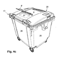
- the hinged lid 5 ' is with its hinge part 8b between the two Hinge tabs 8 of the body inserted and inserted through it Hinge axis 8c pivotally hinged, and can be opened up, as shown in Fig. 4b, but also be folded up to total 270 °, until the hinged lid 5 'behind the rear wall 26 of the body 1 vertically hangs.
- the hinged lid 5 ' also has in its top - as best in Fig. 4c recognize - near its trailing edge 17 an opening 21. This is located enclosed on all sides in the hinged lid 5 'and indeed completely in the middle, deeper area, which is indeed offset from the frontal outer, higher lying areas, where also the hinges 8 of the lid are integrally formed.
- This opening 21 is preferably subsequently mechanically in the hinged lid 5 ' made by sawing or milling, and can by a Sekundärdekkel 9 'are closed, in turn, hinged on the hinged lid 5' turn is fixed, that is also designed as a hinged lid, by means of hinges 8 ', about which of the secondary lid 9 'facing away from the rear wall 26 on its Side, ie to the center of the hinged lid 5 'out, is attached.
- the hinge parts 8 ' are made as usual from each other via an axis Hinge parts, on the one hand on the secondary lid 9 'integrally formed and are sprayed on the hinged lid 5 '- in later production of the opening 21 by mechanical processing - but subsequently attached, so riveted or screwed, are.
- the hinged lid 5 ' can in its front wall 24 facing the front, too opening, area also such a secondary cover 9 'and an associated Have opening, or even another secondary cover 9 with different underneath opening, as explained later on the basis of the swing lid will be.
- the hinged lid 5 can also - as shown in Fig. 4d - no at all on or in him arranged secondary cover and no corresponding Having opening but completely closed, be, as in Fig. 4d than Hinged lid 5 shown.
- the front edge of the hinged lid 5 is not formed by a secondary lid is, is in the hinged lid 5 and 5 'there, in the middle, arranged such a grip.
- the secondary lid 9 serves to inject waste from the back of the container 20 ago, and can with less effort than the entire folding lid 5 'are opened.
- Fig. 1c shows the body 1 'in the design, as he for swing lid 4, 4 'is needed, in the same mounting state as Fig. 1a for the variant 1, namely with already mounted receiving pin unit 29 and Wheels 7 under the floor 27.
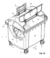
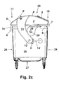
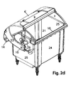
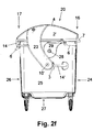
- FIGS. 2a to 2c show the finished assembly state, that is, further completed with a swing lid 4 'in the pushed state of this swing lid 4 ', while Fig. 2d this swing cover 4' in the pushed back state shows.
- this swing lid 4 ' is known to include one each laterally outside the end walls 25 in each downwardly extending strut 23, by means of the swing cover 4 'to a transverse direction 10 extending Swing axis 10 'from the closed position, in which it the opening 21st in the form of the open top of the body 1 'closes, pushed backwards and can be panned.
- the pivot axis 10 ' is realized by the side walls 25 in the transverse direction 10 outwardly projecting axle journals, which in the journal unit. 3 are included, which are screwed onto the side walls 25.
- the journalling unit 3 Since the spindle unit 3 for reducing the operating forces a supporting, contains invisible spring, the journalling unit 3 also requires a support of the torque around the pivot axis 10 'around, in Form of a transverse strut strut 3 'is formed, the free end in turn is screwed to the side wall 25. However, the middle part of the strut 3 'is so far spaced to the side wall 25 formed that he as an additional Handle can be used.
- the lid strut 23 is formed curved in the side view and guided around the receiving pin 28 around.
- this also has side walls in the form of Bends 2 ', which are also integral part of the swing lid 4', so that in the side view of the lid has a straight lower edge.
- FIG. 2c and 2d show are in the Schwingdekkel variant of the container 20 on the side walls 25 only in the front mounting holes 13 push-in handles 6 inserted, but not in the rear mounting holes, there a slanting outward in the grip with the Swing lid 4, in particular its strut 23, would collide when opening.
- a handle is formed on the swing lid 4 'itself, as shown in FIGS. 2 mitgefickt as a hard grip 14 in one piece, and above from the side Edge in the rear area down, so behind the strut 23rd
- Fig. 2b reveals that the body 1 'at its upper trailing edge 17 in the left and right areas symmetrical to each other also has pairs of receiving openings 13 integrated in its edge 12, and there are also each handles 6 are mounted to move the container 20th
- the body 1 ' differs from the body 1 in the area of this entire upper trailing edge 17 by the absence of molded on the body 1 Hinges 8 and instead the presence of the mounting holes 13th at the body 1 '.
- body 1 and body 1 ' are made with the same basic injection molding tool produced. Since the shape of such an injection molding tool consists of several complementary parts, in this case, the shape is in Parts divided, that on the one of the shape of the upper trailing edge 17 determining Form part or these several moldings are changed on the mold can, depending on whether variant 1 or 1 'is needed.
- FIGS. 2b to 2d show a variant 4 'of the oscillating lid, in which two more Secondary lid, both of which are designed as hinged lid, are integrated, such as best seen in Fig. 2a, in which both secondary covers 9, 9 'in the unfolded State relative to the primary lid 4 'are shown.
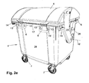
- the swing lid 4 '- as well as the hinged lid 5' - even only have one of these secondary lid or no secondary lid, so even be completely closed, as is the case in Fig. 2e, f.
- the secondary cover 9' - which is identical to that in the hinged lid according to FIG. 4 - also arranged near the trailing edge 17 in the swing lid 4 ', and encloses as described above, an enclosed opening 21 in the swing lid 4 '.
- the hinges 8' for this secondary cover 9 ' subsequently mounted on the swing lid 4' and the opening 21 cut out, however - if this is from the quantities worth - these elements by means of a modified injection mold already in the production the swing cover 4 'may be provided, so the hinges 8' then in one piece be sprayed with, and the opening 21 to be produced during spraying.
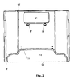
- Figures 2a to 2d further show a secondary lid 9 near the leading edge 16 of the swing lid 4 ', which has a recess 18 in its closed State closes, which extends into the front edge 16 of the swing lid 4 ', as in Fig. 2a, but also in the detail supervision of Fig. 3 on this Swing cover best to recognize.
- the recess 18 removes the straight, continuous front edge 16 of the Swinging lid 4 'almost on its entire length, leaving only the left and left over left corners. This serves to prevent the pinching of Persons, especially children, between closed swing lid 4 'and Body 1 ', which is difficult due to the necessary opening direction own liberation is possible.
- FIGS. 2 a and 3 show, the edge 22 of the recess 18 projects upwards and thickened trained, and in particular as a more enclosed Cavity, z. B. prepared by the water injection technique.
- the increase upwards on the one hand serves the stiffening of the Schwingdekkels 4 ', but above all, the prevention of the inrun of water along the curved surface of the swing lid 4 'in the opening 18 below the only loosely resting secondary cover 9 therethrough.
- the hinges 8 'for the secondary lid 9' already mounted or mitangespritzt, for the hinges of the secondary lid 9 are only the holes for screwing the hinges available.
- FIGS. 5a to 5d show one of the bodies 1, 1 'and / or on the covers 4, 5 used handles 6 in detail:
- the plug handle 6 shown in the remaining drawings is in the plan U-shaped, as shown in Fig. 5b, with a middle leg as Handle part 6b, from the ends of which in the same direction grip leg 6c strive, whose free ends are designed as plug-in parts 6a for insertion into the blind-hole-shaped mounting holes 13, 13 'as in the assembled state Fig. 5d shown.
- the handle part 6b is preferably ergonomic reasons with a round Cross-section equipped and preferably as a completely enclosed cavity, z. B. prepared by the water injection technique.
- Fig. 5a While in Fig. 5a, only the handle portion 6b enclosed in this manner hollow is designed, the leg portions 6c, however, a one-sided, z. B. down, open z. B. U-profile and the plug part 6a is solid, the Fig. Shows. 6b shows a section through the leg part 6c, in which the enclosed Cavity up to the solidity reasons also solid trained Plug-in part 6a is enough. The cavity can be up to about the locking lug 15th range, if this still sufficient stability of the plug handle. 6 results.
- the locking lug 15 is on the plug-in part 6a, which is preferably a rectangular Has cross-section, preferably formed on the front surface protruding with an obliquely upward into the front surface of the male part 6a Sloping surface and a perpendicular thereto underside.
- This free ending leg of the edge 12 is through the inclined surface the locking lug 15 pressed from the bottom outward during its insertion, until the edge over the locking lug 15 snaps and this in the latching opening 15 'is located.
- the handle part 6b a sufficient distance from the wall 11 of the body is, as the side views of Fig. 5a and 5d show - the leg 6c cranked by the male part 6a in a preferably obtuse angle, so that despite the vertically downwardly directed attachment opening 13, the handle part 6b spaced from the wall 11 is located.
- Fig. 5c shows a variant 6 'of the plug handle, wherein the free ends of the Leg parts 6c via a common plug leg 6c 'to a closed Form of the plug-in handle 6 'are connected, which increases its stability.
- the entire transverse leg is as a plug-in part 6c 'in a correspondingly wide dimensioned mounting hole 13 'pushed, and of course in turn analog locking means, for. B. latching lugs 15.
Landscapes
- Engineering & Computer Science (AREA)
- Mechanical Engineering (AREA)
- Closures For Containers (AREA)
Abstract
Description
- Fig. 1a, b:
- Unterschiedliche Montagezustände einer ersten Korpusvariante,
- Fig. 1c:
- eine zweite Korpusvariante,
- Fig. 2:
- den Behälter mit Schwingdeckel,
- Fig. 3:
- den Schwingdeckel alleine in der Aufsicht,
- Fig. 4:
- den Behälter mit Klappdeckel und
- Fig. 5:
- Detaildarstellungen des Steckgriffes.
- 1,1'
- Korpus
- 2
- Bogen
- 3
- Achszapfen-Einheit
- 4, 4'
- Schwingdeckel
- 5, 5'
- Klappdeckel
- 6
- Steckgriff
- 6a
- Steckteil
- 6b
- Griffteil
- 6c
- Griffschenkel
- 7
- Rad
- 8
- Scharnier
- 9, 9'
- Sekundärdeckel
- 10
- Querrichtung
- 10'
- Schwingachse
- 11
- Wand
- 12
- Rand
- 13, 13'
- Befestigungsöffnung
- 14
- Festgriffe
- 15
- Rastnase
- 16
- Vorderkante
- 17
- Hinterkante
- 18
- Ausnehmung
- 19
- Verschluss
- 20
- Großbehälter
- 21
- Öffnung
- 22
- Rand
- 23
- Strebe
- 24
- Frontwand
- 25
- Seitenwand
- 26
- Rückwand
- 27
- Boden
- 28
- Aufnahmezapfen
- 29
- Aufnahmeeinheit
- 30
- Buchse
- 31
- Metallrohr
- 32a,b
- Rippe
- 33
- Rand
- 34
- Sacklöcher
- 35
- Vertikalöffnung
- 36
- Flachmaterial
- 37
- Profil
- 37'
- Winkelprofil
- 38
- Aufnahmeraum
- 39
- stirnseitige Öffnung
- 40
- Außenwand
- 41
- Kröpfung
Claims (14)
- Bausatz für Müllbehälter, insbesondere Großbehälter (20), mitdadurch gekennzeichnet, dasswenigstens einem oben offenen, topfförmigen Korpus (1, 1'),wenigstens einem Deckel, insbesondere Schwingdeckel (4) oder Klappdeckel (5) zum Verschließen des Korpus,der Bausatz wenigstens einen nachträglich montierbaren Griff, insbesondere Steckgriff (6) umfasst sowiean dem wenigstens einen Korpus (1, 1') und/oder dem wenigstens einen Dekkel Befestigungsvorrichtungen für wenigstens einen nachträglich montierbaren Griff, insbesondere Befestigungsöffnungen (13, 13') für wenigstens einen Steckgriff (6), angeordnet sind, und insbesondereder Bausatz nur einen Korpus (1') mit in der Seitenansicht bogenförmigem oberem Abschluss (Bogen 2) umfasst und der Klappdeckel (5) in der Seitenansicht ebenfalls hierzu passend bogenförmig ausgebildet ist.
- Bausatz für Müllbehälter, insbesondere Großbehälter (20) mitdadurch gekennzeichnet, dasswenigstens einem Korpus (1, 1'),einem Schwingdeckel (4),einer Achs-Zapfeneinheit (3) zum Anlenken des Schwingdeckels (4),einem Klappdeckel (5),Scharnieren (8) zum Anlenken des Klappdeckels (5),
der Bausatz wenigstens einen separaten Griff, insbesondere Steckgriffe (6), umfaßt. - Bausatz nach einem der vorhergehenden Ansprüche,
dadurch gekennzeichnet, dass- der Bausatz einen Korpus (1') mit in der Seitenansicht bögenförmigem oberen Abschluss sowie einen Korpus (1) mit geradem oberen Abschluss und ansonsten gleichen Abmessungen umfasst, und/oder insbesondereder Bausatz nur einen Korpus (1) mit in der Seitenansicht geradem oberen Abschluss sowie die Seitenwände des Korpus (1) nach oben verlängernden, insbesondere am Korpus (1) aufsteckbaren, Bögen (2) umfasst, und/oder insbesondeream Korpus (1, 1') und/oder am Schwingdeckel (4) und/oder am Klappdeckel (5) Befestigungsvorrichtungen, insbesondere Befestigungsöffnungen (13), zur nachträglichen Befestigung von Griffen, insbesondere Einstecken von Steckgriffen (6), vorhanden sind und insbesondere die am Korpus (1, 1') und/oder an einem der Deckel (4, 5) vorhandenen Griffe als nachträglich montierbare Griffe, insbesondere Steckgriffe (6), ausgebildet sind, und/oder insbesondereder Korpus (1, 1') zusätzlich zu den Befestigungsvorrichtungen für nachträglich montierbare Griffe einstückig ausgebildete Festgriffe (14) umfasst. - Bausatz nach einem der vorhergehenden Ansprüche,
dadurch gekennzeichnet, dassdie Befestigungsöffnungen (13) Sacklöcher sind, und/oder insbesondereim Korpus (1, 1') die Befestigungsöffnungen (13) im nach außen überstehenden Rand (12) als von unten zugängliche Öffnungen ausgebildet sind und insbesondere für jeden der frei endenden Schenkel (6c) des Steckgriffes (6) eine einzelne Öffnung vorhanden ist, und/oder insbesonderealle Steckgriffe (6) wenigstens das gleiche Befestigungsteil, insbesondere Steckteil (6a), umfassen. - Bausatz nach einem der vorhergehenden Ansprüche,
dadurch gekennzeichnet, dassdie Steckgriffe (6) als ringförmig geschlossene Griffe (6') ausgebildet sind und der gesamte durchgehende Basisschenkel (6a') in entsprechende Befestigungsöffnungen (13') einschiebbar ist, und/oder insbesonderedas Steckteil (6a, 6a') des Steckgriffes (6, 6') wenigstens einen Rasthaken (15) aufweist, der sich nach Einschieben in die Befestigungsöffnungen im aufnehmenden Bauteil, insbesondere im Korpus (1, 1') insbesondere einer dortigen Ausnehmung (15') formschlüssig verhakt gegen ein herausziehen, und/oder insbesonderedie Steckgriffe (6, 6') in der Seitenansicht gekröpft ausgebildet sind mit einem stumpfen Winkel zwischen dem Steckteil (6a) und dem Griffteil (6b), welcher zum Griffschenkel (6c) führt. - Bausatz nach einem der vorhergehenden Ansprüche
dadurch gekennzeichnet, dassder Bausatz Räder (7) umfasst, die am Korpus (1, 1') einsteckbar sind, und/oder insbesondereder Korpus ein Verschlussteil zum Abdecken der Aufnahme für die Zapfeneinheit (3) umfasst, und/oder insbesondereder Primärdeckel, also Schwingdeckel (4) und/oder Klappdeckel (5), in zwei Varianten, nämlich einstückig oder mit wenigstens einem integriertem Sekundärdeckel (9, 9') vorhanden ist, und/oder insbesondereder gleiche Sekundärdeckel (9, 9') sowohl am Schwingdeckel (4') als auch am Klappdeckel (5') verwendbar ist, und insbesondere Schwingdeckel (4') und Klappdeckel (5') in der Seitenansicht eine voneinander verschiedene Grundform im Bereich des Sekundärdeckels (9 bzw. 9') jedoch eine übereinstimmende Formgebung aufweist, und/oder insbesondereder Sekundärdeckel (9) Bestandteil der Vorderkante des Primärdeckels, insbesondere Schwingdeckels (4') oder Klappdeckels (5'), ist und eine in die Vorderkante (16) hineinreichende Ausnehmung (18) des Primärdeckels verschließt, und/oder insbesondereder Sekundärdeckel (9') ein allseitig auf dem Primärdeckel, insbesondere Klappdeckel (5') oder Schwingdeckel (4'), aufliegender und/oder ein eine vom Primärdeckel allseitig umschlossene Öffnung (21) verschließender, Deckel ist. - Bausatz nach einem der vorhergehenden Ansprüche,
dadurch gekennzeichnet, dassder Rand (22) des Deckels, insbesondere Klappdeckels (5') oder Schwingdekkels (4'), entlang der Ausnehmung (18) und/oder um die Öffnung (21) herum als geschlossenes Hohlprofil, insbesondere hergestellt mittels der Wasser-Injektions-Technik, beim Kunststoff-Spritzgießen zusammen mit dem übrigen Deckel ausgebildet ist, und/oder insbesonderedie nachträglich montierbaren Griffe, insbesondere Steckgriffe (6), und/oder die Strebe (23) des Schwingdeckels (4, 4') als Hohlteile, insbesondere allseitig geschlossene Hohlteile aus Kunststoff, insbesondere hergestellt nach der Wasser-Injektions-Technik, ausgebildet sind. - Bausatz nach einem der vorhergehenden Ansprüche,
dadurch gekennzeichnet, dassdie Scharniere (8) mittels Einstecken und Verrasten am Korpus (1 bzw. 1') montiert werden, insbesondere ohne zusätzliche Sicherungsverschraubung, und/oder insbesonderedie Scharniere (8) das gleiche Steckteil (6a) aufweisen wie die Steckgriffe (6) und in die gleichen Befestigungsöffnungen (13) eingebracht werden können, und/oder insbesondere die Scharniere (8) so breit ausgebildet sind, dass sie als Handgriff nutzbar sind. - Bausatz nach einem der vorhergehenden Ansprüche,
dadurch gekennzeichnet, dassder Schwingdeckel (4, 4') an den Seitenwänden (25), nahe der Hinterkante (7), einen Festgriff (14) aufweist und/oder insbesondereder Bausatz die Aufnahmezapfen-Einheit (19) umfasst. - Bausatz nach einem der vorhergehenden Ansprüche,
dadurch gekennzeichnet, dass
der die Öffnung (21) umgebende, insbesondere erhöhte Rand (22') des Primärdeckels und/oder die Scharniere für den diese verschließende Sekundärdeckel (9') auf den Primärdeckel nachträglich befestigt, insbesondere vernietet oder verschraubt, wird. - Bausatz nach einem der vorhergehenden Ansprüche,
dadurch gekennzeichnet, dass
die Steckgriffe (6) in zwei unterschiedlichen Stellungen in ein und dieselben Befestigungsöffnungen (13), insbesondere des Primärdeckels, eingesteckt werden können. - Bausatz nach einem der vorhergehenden Ansprüche,
dadurch gekennzeichnet, dassder Klappdeckel (5') und/oder der Schwingdeckel (4') zwei Sekundärdeckel (9') für vollständig umschlossene Öffnungen an ihren vorderen und hinteren Bereich aufweisen und/oder insbesondereder Schwingdeckel (4 bzw. 4') an seinem oberen stirnseitigem Bogen (2) nahe seiner Hinterkante einen Griff, insbesondere einen einstückig fest angeformten Festgriff (14), aufweist und/oder insbesondereder Korpus (1') für die Klappdeckel (5, 5') einstückig angeformte Scharniere (8) oder wenigstens Scharnierlaschen aufweist, jedoch keine Befestigungsöffnungen (13) für Steckgriffe an seiner Hinterkante (17). - Bausatz nach einem der vorhergehenden Ansprüche,
dadurch gekennzeichnet, dass
der Korpus (1) für den Schwingdeckel (4, 4') mit einstückig angeformten Bögen (2) einerseits und der Korpus (1') für Klappdeckel mit einstückig angeformten Scharnieren (8) an der Hinterkante andererseits sich außer im Bereich der gesamten hinteren Oberkante (17) und dem Vorhandensein oder Fehlen der Bögen (2) nicht unterscheiden und mit im wesentlichen der gleichen Spritzform - gegen Austausch der Formteile in diesen Bereichen - herstellbar sind. - Bausatz nach einem der vorhergehenden Ansprüche,
dadurch gekennzeichnet, dass
die Öffnung (21), die vom Sekundärdeckel (9') verschlossen wird, mittels Ausschneiden oder Ausfräsen aus dem Deckel nachträglich hergestellt und durch Aufschrauben, Aufnieten oder Aufkleben eines erhöhten umlaufenden Randes (22'), insbesondere mit Scharnierlaschen (8'), zum Auflegen des Sekundärdeckels (21) verstärkt ist.
Applications Claiming Priority (2)
| Application Number | Priority Date | Filing Date | Title |
|---|---|---|---|
| DE10216804A DE10216804C1 (de) | 2002-04-16 | 2002-04-16 | Bausatz mit Steckgriffen |
| DE10216804 | 2002-04-16 |
Publications (2)
| Publication Number | Publication Date |
|---|---|
| EP1354824A1 true EP1354824A1 (de) | 2003-10-22 |
| EP1354824B1 EP1354824B1 (de) | 2017-01-04 |
Family
ID=27798284
Family Applications (1)
| Application Number | Title | Priority Date | Filing Date |
|---|---|---|---|
| EP03400013.3A Expired - Lifetime EP1354824B1 (de) | 2002-04-16 | 2003-04-16 | Bausatz für einen Müllbehälter mit Steckgriffen |
Country Status (2)
| Country | Link |
|---|---|
| EP (1) | EP1354824B1 (de) |
| DE (1) | DE10216804C1 (de) |
Cited By (3)
| Publication number | Priority date | Publication date | Assignee | Title |
|---|---|---|---|---|
| EP2384998A1 (de) | 2010-05-07 | 2011-11-09 | Environmental Solutions Europe Holding B.V. | Deckel für einen Müllbehälter sowie Müllbehälter |
| EP2388212A1 (de) | 2010-05-21 | 2011-11-23 | Environmental Solutions Europe Holding B.V. | Deckel für einen Müllbehälter sowie Müllbehälter |
| EP4282782A1 (de) | 2022-05-25 | 2023-11-29 | ESE World B.V. | Grossabfallsammelbehälter |
Families Citing this family (2)
| Publication number | Priority date | Publication date | Assignee | Title |
|---|---|---|---|---|
| DE202004010416U1 (de) * | 2004-06-30 | 2005-11-10 | Rühland, Lothar | Sammelbehälter |
| EP4282781B1 (de) * | 2022-05-25 | 2026-05-13 | ESE World B.V. | Grossabfallsammelbehälter |
Citations (4)
| Publication number | Priority date | Publication date | Assignee | Title |
|---|---|---|---|---|
| DE2951328A1 (de) * | 1979-12-20 | 1981-07-23 | Sulo Eisenwerk Streuber & Lohmann Gmbh & Co Kg, 4900 Herford | Grossraum-muellbehaelter aus kunststoff |
| EP1038803A1 (de) * | 1999-03-25 | 2000-09-27 | Egbert H. Taylor & Company Limited | Mit Laufrädern versehener Müllbehälter |
| DE20205927U1 (de) * | 2002-04-16 | 2002-07-04 | SULO Umwelttechnik GmbH & Co. KG, 32051 Herford | Verstärkte Zapfen-Aufnahme |
| DE20205928U1 (de) * | 2002-04-16 | 2002-07-04 | SULO Umwelttechnik GmbH & Co. KG, 32051 Herford | Müllbehälter-Korpus |
Family Cites Families (2)
| Publication number | Priority date | Publication date | Assignee | Title |
|---|---|---|---|---|
| DE4129163C1 (de) * | 1991-09-02 | 1993-03-18 | Edelhoff Polytechnik Gmbh & Co, 5860 Iserlohn, De | |
| DE4311063A1 (de) * | 1993-03-08 | 1994-09-15 | Bock Norman | Behälter zur Aufnahme der Entsorgung zuzuführender Abfälle |
-
2002
- 2002-04-16 DE DE10216804A patent/DE10216804C1/de not_active Expired - Lifetime
-
2003
- 2003-04-16 EP EP03400013.3A patent/EP1354824B1/de not_active Expired - Lifetime
Patent Citations (4)
| Publication number | Priority date | Publication date | Assignee | Title |
|---|---|---|---|---|
| DE2951328A1 (de) * | 1979-12-20 | 1981-07-23 | Sulo Eisenwerk Streuber & Lohmann Gmbh & Co Kg, 4900 Herford | Grossraum-muellbehaelter aus kunststoff |
| EP1038803A1 (de) * | 1999-03-25 | 2000-09-27 | Egbert H. Taylor & Company Limited | Mit Laufrädern versehener Müllbehälter |
| DE20205927U1 (de) * | 2002-04-16 | 2002-07-04 | SULO Umwelttechnik GmbH & Co. KG, 32051 Herford | Verstärkte Zapfen-Aufnahme |
| DE20205928U1 (de) * | 2002-04-16 | 2002-07-04 | SULO Umwelttechnik GmbH & Co. KG, 32051 Herford | Müllbehälter-Korpus |
Cited By (5)
| Publication number | Priority date | Publication date | Assignee | Title |
|---|---|---|---|---|
| EP2384998A1 (de) | 2010-05-07 | 2011-11-09 | Environmental Solutions Europe Holding B.V. | Deckel für einen Müllbehälter sowie Müllbehälter |
| DE102010019780A1 (de) | 2010-05-07 | 2011-11-10 | Environmental Solutions Europe Holding B.V. | Deckel für einen Müllbehälter sowie Müllbehälter |
| EP2388212A1 (de) | 2010-05-21 | 2011-11-23 | Environmental Solutions Europe Holding B.V. | Deckel für einen Müllbehälter sowie Müllbehälter |
| DE102010021170A1 (de) | 2010-05-21 | 2011-11-24 | Environmental Solutions Europe Holding B.V. | Deckel für einen Müllbehälter sowie Müllbehälter |
| EP4282782A1 (de) | 2022-05-25 | 2023-11-29 | ESE World B.V. | Grossabfallsammelbehälter |
Also Published As
| Publication number | Publication date |
|---|---|
| DE10216804C1 (de) | 2003-10-02 |
| EP1354824B1 (de) | 2017-01-04 |
Similar Documents
| Publication | Publication Date | Title |
|---|---|---|
| CH683838A5 (de) | Behälter. | |
| DE69313846T2 (de) | Vielseitiger, doppelt wirkender müllbehälterdeckel | |
| DE69723949T2 (de) | Aufzuhängender Lagerschrank | |
| WO2009153694A2 (de) | Klappbarer transport- und lagerbehälter | |
| DE20209288U1 (de) | Abfallkorb für einen Papiershredder | |
| EP1884438B1 (de) | Rollbehälter für Stückgut | |
| EP1354824B1 (de) | Bausatz für einen Müllbehälter mit Steckgriffen | |
| EP0668188B1 (de) | Deckelverriegelung für die Abdeckung von Behältnissen in Kraftfahrzeugen | |
| DE2633553A1 (de) | Fahrbarer, durch klappdeckel verschliessbarer muellgrossbehaelter | |
| EP1428771B1 (de) | Müllbehälter mit Sekundärdeckel | |
| EP1584425B1 (de) | Tragbare mobilbox | |
| EP2905244A1 (de) | Abdeckung für einen Aufnahmebehälter und Aufnahmebehälter, insbesondere Abfallsammler, mit einer Abdeckung | |
| EP1900892B1 (de) | Drehstangenverschluss | |
| DE3442835C2 (de) | Verschlußvorrichtung für eine abklappbare Abdeckplatte einer Gehäuseöffnung an einem Haushaltgerät | |
| DE29922447U1 (de) | Abdichtbarer Behälter | |
| CH695684A5 (de) | Behälter für Lebensmittel. | |
| EP0442479B1 (de) | Transportabler Vorrats- und/oder Lagerbehälter, insbesondere für Werkzeuge | |
| DE9314627U1 (de) | Gehäuse für elektrische Geräte | |
| EP0423515A1 (de) | Abfallsammler | |
| EP0411316A1 (de) | Klappe | |
| EP0909723B1 (de) | Abfallbehälter | |
| DE20205928U1 (de) | Müllbehälter-Korpus | |
| EP2384998A1 (de) | Deckel für einen Müllbehälter sowie Müllbehälter | |
| EP0939187A1 (de) | Speisentransportbehälter | |
| DE4332243B4 (de) | Fahrzeuggepäckbox, insbesondere Dachkoffer für Kraftfahrzeuge |
Legal Events
| Date | Code | Title | Description |
|---|---|---|---|
| PUAI | Public reference made under article 153(3) epc to a published international application that has entered the european phase |
Free format text: ORIGINAL CODE: 0009012 |
|
| AK | Designated contracting states |
Kind code of ref document: A1 Designated state(s): AT BE BG CH CY CZ DE DK EE ES FI FR GB GR HU IE IT LI LU MC NL PT RO SE SI SK TR |
|
| AX | Request for extension of the european patent |
Extension state: AL LT LV MK |
|
| 17P | Request for examination filed |
Effective date: 20031201 |
|
| AKX | Designation fees paid |
Designated state(s): AT BE BG CH CY CZ DE DK EE ES FI FR GB GR HU IE IT LI LU MC NL PT RO SE SI SK TR |
|
| AXX | Extension fees paid |
Extension state: LT Payment date: 20030416 Extension state: LV Payment date: 20030416 |
|
| RAP1 | Party data changed (applicant data changed or rights of an application transferred) |
Owner name: SULO UMWELTTECHNIK GMBH |
|
| 17Q | First examination report despatched |
Effective date: 20081015 |
|
| GRAP | Despatch of communication of intention to grant a patent |
Free format text: ORIGINAL CODE: EPIDOSNIGR1 |
|
| INTG | Intention to grant announced |
Effective date: 20160722 |
|
| GRAS | Grant fee paid |
Free format text: ORIGINAL CODE: EPIDOSNIGR3 |
|
| GRAA | (expected) grant |
Free format text: ORIGINAL CODE: 0009210 |
|
| AK | Designated contracting states |
Kind code of ref document: B1 Designated state(s): AT BE BG CH CY CZ DE DK EE ES FI FR GB GR HU IE IT LI LU MC NL PT RO SE SI SK TR |
|
| AX | Request for extension of the european patent |
Extension state: LT LV |
|
| REG | Reference to a national code |
Ref country code: GB Ref legal event code: FG4D Free format text: NOT ENGLISH |
|
| REG | Reference to a national code |
Ref country code: CH Ref legal event code: EP |
|
| REG | Reference to a national code |
Ref country code: AT Ref legal event code: REF Ref document number: 858997 Country of ref document: AT Kind code of ref document: T Effective date: 20170115 |
|
| REG | Reference to a national code |
Ref country code: IE Ref legal event code: FG4D Free format text: LANGUAGE OF EP DOCUMENT: GERMAN |
|
| REG | Reference to a national code |
Ref country code: DE Ref legal event code: R096 Ref document number: 50315603 Country of ref document: DE |
|
| REG | Reference to a national code |
Ref country code: FR Ref legal event code: PLFP Year of fee payment: 15 |
|
| REG | Reference to a national code |
Ref country code: LT Ref legal event code: MG9D Ref country code: NL Ref legal event code: MP Effective date: 20170104 |
|
| PG25 | Lapsed in a contracting state [announced via postgrant information from national office to epo] |
Ref country code: NL Free format text: LAPSE BECAUSE OF FAILURE TO SUBMIT A TRANSLATION OF THE DESCRIPTION OR TO PAY THE FEE WITHIN THE PRESCRIBED TIME-LIMIT Effective date: 20170104 |
|
| PG25 | Lapsed in a contracting state [announced via postgrant information from national office to epo] |
Ref country code: FI Free format text: LAPSE BECAUSE OF FAILURE TO SUBMIT A TRANSLATION OF THE DESCRIPTION OR TO PAY THE FEE WITHIN THE PRESCRIBED TIME-LIMIT Effective date: 20170104 Ref country code: GR Free format text: LAPSE BECAUSE OF FAILURE TO SUBMIT A TRANSLATION OF THE DESCRIPTION OR TO PAY THE FEE WITHIN THE PRESCRIBED TIME-LIMIT Effective date: 20170405 |
|
| PG25 | Lapsed in a contracting state [announced via postgrant information from national office to epo] |
Ref country code: PT Free format text: LAPSE BECAUSE OF FAILURE TO SUBMIT A TRANSLATION OF THE DESCRIPTION OR TO PAY THE FEE WITHIN THE PRESCRIBED TIME-LIMIT Effective date: 20170504 Ref country code: BG Free format text: LAPSE BECAUSE OF FAILURE TO SUBMIT A TRANSLATION OF THE DESCRIPTION OR TO PAY THE FEE WITHIN THE PRESCRIBED TIME-LIMIT Effective date: 20170404 Ref country code: ES Free format text: LAPSE BECAUSE OF FAILURE TO SUBMIT A TRANSLATION OF THE DESCRIPTION OR TO PAY THE FEE WITHIN THE PRESCRIBED TIME-LIMIT Effective date: 20170104 Ref country code: SE Free format text: LAPSE BECAUSE OF FAILURE TO SUBMIT A TRANSLATION OF THE DESCRIPTION OR TO PAY THE FEE WITHIN THE PRESCRIBED TIME-LIMIT Effective date: 20170104 |
|
| REG | Reference to a national code |
Ref country code: DE Ref legal event code: R097 Ref document number: 50315603 Country of ref document: DE |
|
| PG25 | Lapsed in a contracting state [announced via postgrant information from national office to epo] |
Ref country code: EE Free format text: LAPSE BECAUSE OF FAILURE TO SUBMIT A TRANSLATION OF THE DESCRIPTION OR TO PAY THE FEE WITHIN THE PRESCRIBED TIME-LIMIT Effective date: 20170104 Ref country code: RO Free format text: LAPSE BECAUSE OF FAILURE TO SUBMIT A TRANSLATION OF THE DESCRIPTION OR TO PAY THE FEE WITHIN THE PRESCRIBED TIME-LIMIT Effective date: 20170104 Ref country code: CZ Free format text: LAPSE BECAUSE OF FAILURE TO SUBMIT A TRANSLATION OF THE DESCRIPTION OR TO PAY THE FEE WITHIN THE PRESCRIBED TIME-LIMIT Effective date: 20170104 Ref country code: SK Free format text: LAPSE BECAUSE OF FAILURE TO SUBMIT A TRANSLATION OF THE DESCRIPTION OR TO PAY THE FEE WITHIN THE PRESCRIBED TIME-LIMIT Effective date: 20170104 Ref country code: IT Free format text: LAPSE BECAUSE OF FAILURE TO SUBMIT A TRANSLATION OF THE DESCRIPTION OR TO PAY THE FEE WITHIN THE PRESCRIBED TIME-LIMIT Effective date: 20170104 |
|
| PLBE | No opposition filed within time limit |
Free format text: ORIGINAL CODE: 0009261 |
|
| STAA | Information on the status of an ep patent application or granted ep patent |
Free format text: STATUS: NO OPPOSITION FILED WITHIN TIME LIMIT |
|
| PG25 | Lapsed in a contracting state [announced via postgrant information from national office to epo] |
Ref country code: DK Free format text: LAPSE BECAUSE OF FAILURE TO SUBMIT A TRANSLATION OF THE DESCRIPTION OR TO PAY THE FEE WITHIN THE PRESCRIBED TIME-LIMIT Effective date: 20170104 |
|
| REG | Reference to a national code |
Ref country code: CH Ref legal event code: PL |
|
| 26N | No opposition filed |
Effective date: 20171005 |
|
| GBPC | Gb: european patent ceased through non-payment of renewal fee |
Effective date: 20170416 |
|
| REG | Reference to a national code |
Ref country code: IE Ref legal event code: MM4A |
|
| PG25 | Lapsed in a contracting state [announced via postgrant information from national office to epo] |
Ref country code: MC Free format text: LAPSE BECAUSE OF FAILURE TO SUBMIT A TRANSLATION OF THE DESCRIPTION OR TO PAY THE FEE WITHIN THE PRESCRIBED TIME-LIMIT Effective date: 20170104 |
|
| PG25 | Lapsed in a contracting state [announced via postgrant information from national office to epo] |
Ref country code: LU Free format text: LAPSE BECAUSE OF NON-PAYMENT OF DUE FEES Effective date: 20170416 Ref country code: GB Free format text: LAPSE BECAUSE OF NON-PAYMENT OF DUE FEES Effective date: 20170416 Ref country code: LI Free format text: LAPSE BECAUSE OF NON-PAYMENT OF DUE FEES Effective date: 20170430 Ref country code: CH Free format text: LAPSE BECAUSE OF NON-PAYMENT OF DUE FEES Effective date: 20170430 Ref country code: SI Free format text: LAPSE BECAUSE OF FAILURE TO SUBMIT A TRANSLATION OF THE DESCRIPTION OR TO PAY THE FEE WITHIN THE PRESCRIBED TIME-LIMIT Effective date: 20170104 |
|
| REG | Reference to a national code |
Ref country code: BE Ref legal event code: MM Effective date: 20170430 |
|
| REG | Reference to a national code |
Ref country code: FR Ref legal event code: PLFP Year of fee payment: 16 |
|
| PG25 | Lapsed in a contracting state [announced via postgrant information from national office to epo] |
Ref country code: IE Free format text: LAPSE BECAUSE OF NON-PAYMENT OF DUE FEES Effective date: 20170416 |
|
| PG25 | Lapsed in a contracting state [announced via postgrant information from national office to epo] |
Ref country code: BE Free format text: LAPSE BECAUSE OF NON-PAYMENT OF DUE FEES Effective date: 20170430 |
|
| REG | Reference to a national code |
Ref country code: AT Ref legal event code: MM01 Ref document number: 858997 Country of ref document: AT Kind code of ref document: T Effective date: 20170416 |
|
| PG25 | Lapsed in a contracting state [announced via postgrant information from national office to epo] |
Ref country code: AT Free format text: LAPSE BECAUSE OF NON-PAYMENT OF DUE FEES Effective date: 20170416 |
|
| PG25 | Lapsed in a contracting state [announced via postgrant information from national office to epo] |
Ref country code: HU Free format text: LAPSE BECAUSE OF FAILURE TO SUBMIT A TRANSLATION OF THE DESCRIPTION OR TO PAY THE FEE WITHIN THE PRESCRIBED TIME-LIMIT; INVALID AB INITIO Effective date: 20030416 |
|
| PG25 | Lapsed in a contracting state [announced via postgrant information from national office to epo] |
Ref country code: CY Free format text: LAPSE BECAUSE OF NON-PAYMENT OF DUE FEES Effective date: 20170104 |
|
| PG25 | Lapsed in a contracting state [announced via postgrant information from national office to epo] |
Ref country code: TR Free format text: LAPSE BECAUSE OF FAILURE TO SUBMIT A TRANSLATION OF THE DESCRIPTION OR TO PAY THE FEE WITHIN THE PRESCRIBED TIME-LIMIT Effective date: 20170104 |
|
| PGFP | Annual fee paid to national office [announced via postgrant information from national office to epo] |
Ref country code: FR Payment date: 20220429 Year of fee payment: 20 Ref country code: DE Payment date: 20220420 Year of fee payment: 20 |
|
| REG | Reference to a national code |
Ref country code: DE Ref legal event code: R071 Ref document number: 50315603 Country of ref document: DE |