EP1353420B1 - Dispositif de sertissage - Google Patents
Dispositif de sertissage Download PDFInfo
- Publication number
- EP1353420B1 EP1353420B1 EP03008181A EP03008181A EP1353420B1 EP 1353420 B1 EP1353420 B1 EP 1353420B1 EP 03008181 A EP03008181 A EP 03008181A EP 03008181 A EP03008181 A EP 03008181A EP 1353420 B1 EP1353420 B1 EP 1353420B1
- Authority
- EP
- European Patent Office
- Prior art keywords
- crimping
- die
- indenter
- slot
- elements
- Prior art date
- Legal status (The legal status is an assumption and is not a legal conclusion. Google has not performed a legal analysis and makes no representation as to the accuracy of the status listed.)
- Expired - Lifetime
Links
- 238000002788 crimping Methods 0.000 title claims abstract description 236
- 238000005520 cutting process Methods 0.000 claims description 7
- 239000004020 conductor Substances 0.000 description 35
- 238000000034 method Methods 0.000 description 8
- 230000006835 compression Effects 0.000 description 6
- 238000007906 compression Methods 0.000 description 6
- 238000010276 construction Methods 0.000 description 5
- 238000013459 approach Methods 0.000 description 3
- 238000009413 insulation Methods 0.000 description 3
- 238000012545 processing Methods 0.000 description 3
- 238000006073 displacement reaction Methods 0.000 description 2
- RYGMFSIKBFXOCR-UHFFFAOYSA-N Copper Chemical compound [Cu] RYGMFSIKBFXOCR-UHFFFAOYSA-N 0.000 description 1
- 229910052802 copper Inorganic materials 0.000 description 1
- 239000010949 copper Substances 0.000 description 1
- 230000001419 dependent effect Effects 0.000 description 1
- 238000011161 development Methods 0.000 description 1
- 230000000694 effects Effects 0.000 description 1
- 239000011888 foil Substances 0.000 description 1
- 238000003780 insertion Methods 0.000 description 1
- 230000037431 insertion Effects 0.000 description 1
- 238000009434 installation Methods 0.000 description 1
- 238000003754 machining Methods 0.000 description 1
- 239000002184 metal Substances 0.000 description 1
- 229910052751 metal Inorganic materials 0.000 description 1
- 239000006223 plastic coating Substances 0.000 description 1
- 238000003825 pressing Methods 0.000 description 1
- 230000000452 restraining effect Effects 0.000 description 1
Images


Classifications
-
- H—ELECTRICITY
- H01—ELECTRIC ELEMENTS
- H01R—ELECTRICALLY-CONDUCTIVE CONNECTIONS; STRUCTURAL ASSOCIATIONS OF A PLURALITY OF MUTUALLY-INSULATED ELECTRICAL CONNECTING ELEMENTS; COUPLING DEVICES; CURRENT COLLECTORS
- H01R43/00—Apparatus or processes specially adapted for manufacturing, assembling, maintaining, or repairing of line connectors or current collectors or for joining electric conductors
- H01R43/04—Apparatus or processes specially adapted for manufacturing, assembling, maintaining, or repairing of line connectors or current collectors or for joining electric conductors for forming connections by deformation, e.g. crimping tool
- H01R43/042—Hand tools for crimping
- H01R43/045—Hand tools for crimping with contact member feeding mechanism
-
- H—ELECTRICITY
- H01—ELECTRIC ELEMENTS
- H01R—ELECTRICALLY-CONDUCTIVE CONNECTIONS; STRUCTURAL ASSOCIATIONS OF A PLURALITY OF MUTUALLY-INSULATED ELECTRICAL CONNECTING ELEMENTS; COUPLING DEVICES; CURRENT COLLECTORS
- H01R4/00—Electrically-conductive connections between two or more conductive members in direct contact, i.e. touching one another; Means for effecting or maintaining such contact; Electrically-conductive connections having two or more spaced connecting locations for conductors and using contact members penetrating insulation
- H01R4/10—Electrically-conductive connections between two or more conductive members in direct contact, i.e. touching one another; Means for effecting or maintaining such contact; Electrically-conductive connections having two or more spaced connecting locations for conductors and using contact members penetrating insulation effected solely by twisting, wrapping, bending, crimping, or other permanent deformation
- H01R4/18—Electrically-conductive connections between two or more conductive members in direct contact, i.e. touching one another; Means for effecting or maintaining such contact; Electrically-conductive connections having two or more spaced connecting locations for conductors and using contact members penetrating insulation effected solely by twisting, wrapping, bending, crimping, or other permanent deformation by crimping
- H01R4/182—Electrically-conductive connections between two or more conductive members in direct contact, i.e. touching one another; Means for effecting or maintaining such contact; Electrically-conductive connections having two or more spaced connecting locations for conductors and using contact members penetrating insulation effected solely by twisting, wrapping, bending, crimping, or other permanent deformation by crimping for flat conductive elements, e.g. flat cables
Definitions
- the invention relates to a crimping apparatus according to the recited in claim 1 Art.
- Crimping tools already belong to the well-known state of the art and automatically actuatable crimping or crimping machines. Should with them different crimps are executed, so it is necessary to exchange the respective crimping dies and crimp dies. This is relatively cumbersome and there is a risk that not to Crimpstempeln matching crimping dies, and vice versa, be selected what the risk of Fehlvercrimpungen brings with it. Matching On the other hand, the crimping dies and the crimping dies must be adjusted so that their exchange is relatively time consuming and cumbersome.
- This tool module has a lower module block and an upper module block formed as well as guide columns Guide means for guiding the lower and upper module block relative to each other.
- the module blocks can be coupled to drive means, wherein
- the module blocks can also be used to perform crimping. In this case they are with appropriate punches or dies to provide. An exchange of these punches or dies for implementation other crimping can then easily be done by that the entire tool module is replaced by another one. Consequently ensures that always matching crimping dies and crimp dies can be used and a readjustment of the elements is not required is.
- Several tool modules of this type can be provided at the installation site so that a fitter can perform according to the type of work that can choose just right.
- a disadvantage of the known tool modules is that they are relative heavy and unwieldy and, moreover, are complicated in construction. Should in addition with them on slides located tracks by crimping be connected with each other, so these can be after the connection and if the overall length is too long it is only cumbersome lead out between crimping die and crimping die, as they are there be prevented by the guide columns.
- a crimping device which is a plate-shaped Carrier frame, in which a guide slot for receiving a crimping punch is provided.
- a crimping die is at one end of the Guide slot held so that the crimping die opposite the crimping die lies.
- On the support frame and the crimping die are takeaway provided so that the crimping die on the Crimpgesenk to or from this away is movable.
- the support frame has an interruption that leaves room for eyelets to be able to supply the crimping area, which is held on a strip are, which is guided by means of a guide device, which is a holding plate having the interruption on the page covered by the one Head with its end in advance in the crimping is insertable.
- the invention has the object of providing a further crimping device create, which not only has a simple structure, a fast Exchange of crimping dies and crimping dies is allowed, but the themselves Also better for connecting conductors, especially on films or Like located interconnects by crimping each other is suitable.
- a crimping device contains at least: a plate-shaped Support frame; an existing in the support frame guide slot for receiving a crimping punch; one across the guide slot extending working slot into which the guide slot opens, wherein the working slot extends to an end edge of the support frame; one Crimpgesenk in a slot wall of the working slot; and each on the support frame as well as the crimping stamp existing driving means, over which the Crimping stamp on the crimping die to or can be moved away from this.
- the crimping device may be around a pair of pliers or a Crimping machines for driving carrier frames and crimping dies added be.
- it may have pliers with two working jaws, one of which in each case via the respective driving means the support frame or takes the crimp stamp.
- An exchange of crimping dies and Crimping die is then in a simple manner by replacing the support frame, the crimping die and the crimp die containing assembly possible.
- the construction unit Moreover, it has a simple structure, as it is preferably in one piece trained support frame only as a movable part of the crimping die has to absorb.
- FPC flat printed circuit
- the entrainment means are openings for receiving axle pieces, and the like, or they are as lugs designed so that about these axles or lugs drive means, such as Working jaws of a pair of pliers, on the support frame or the crimping die can act.
- the crimping die After a very advantageous development of the invention carries the crimping die a down to him lying down, the one in the area between the crimping die and the crimping die fixed that he presses against the slit wall of the working slot, in which the crimping die is located.
- the item can be, for example be formed by two superimposed FPC conductor.
- the corresponding Foils are then passed through before and during the crimping process Hold down fixed, so that the relative position of the parts to be crimped can not change during the crimping process. To this This way, clean crimping results or conductor connections are achieved.
- the hold-down is seen in the longitudinal direction of the working slot on both sides of the preferably designed as a rectangular column Crimpstkovs.
- the hold down is also in the guide slot of the crimping die, wherein between Crimpstempel and hold down a spring device acts, the tries to face the edge of the hold-down facing the crimping die the corresponding end edge of the crimping die, thus, that this end edge of the blank holder, the front edge of the crimping die surmounted.
- crimping die is by crimping dies and Hold-down a chamber formed in the side of a crimp insertable is, then pressed by the crimping punch in the direction of Crimpgesenk becomes.
- the crimping element is thus positioned and guided inside the chamber, when it is moved towards the crimping die, resulting in an improved Crimp quality leads.
- the hold-down device has a longitudinal direction the guide slot extending slot on which an axle or a Approach of Crimpstempels absorbs. This allows the movement the hold-down relative to the crimping die in the longitudinal direction of the guide slot control in a simple way. Will the crimp die from the crimp die moved away, he takes the hold-down after a certain time, if the axle piece or the approach against the slot in this direction Restraining wall of holddown is running.
- the support frame according to the invention advantageously carries a feed unit for feeding crimping elements to the crimp die, a simpler one and to ensure error-free feeding of the crimping elements.
- a feed unit for feeding crimping elements to the crimp die, a simpler one and to ensure error-free feeding of the crimping elements.
- example meadow can the feed unit ⁇ -shaped crimping with a Transport base and two parallel legs in one direction, which lies perpendicular to the plane spanned by the base and legs. The legs come to rest so that these in the direction of the crimping die wise and seen in the longitudinal direction of the working slot one behind the other lie. Once they are in through the hold down and the crimping punch formed chamber, they can through the crimping punch moved further with their free leg ends in the direction of the crimping die become.
- the hold-down may preferably surround the crimping punch on three sides and thus in the region of the chamber one in the feed direction of the crimping elements form lying stop to the carrier frame supplied To position crimping elements relative to the crimping die. It can the Stop be designed so that against him only the legs of the crimping elements are feasible. Be banded together over their base Crimping elements fed to the support frame and in their connection area Cut off from the remaining crimping elements, the positioning depends the crimping elements located in the support frame no longer from the Position of the cut so that it does not lead to incorrect positioning of the crimping elements can come within the support framework.
- the feed unit has a support surface for the Crimping elements, which extends to the path of the crimping die, wherein the facing edges of crimping die and support surface form a cutting device. Through them can be easily already introduced into the chamber crimping elements of the remaining and band-shaped Separate interconnected crimping elements.
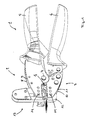
- FIG. 1 shows a perspective view of a crimping apparatus according to FIG Invention with pliers drive.
- a trained in a known manner pliers 1 has an upper Anlagenbakken 2 and a lower working jaw 3, which is about a common axis 4 are pivotable.
- the pivoting of the working jaws 2, 3 is done by Actuation of handles 5, 6, such that upon movement of the handles 5, 6 on the work jaws 2, 3 are pivoted about the axis 4, that closes a pliers mouth 7 formed by them, and vice versa.
- the forceps jaw 7 opens the detailed structure of the pliers 1 itself will not be discussed further here because pliers of this type are well known.
- Each of the working jaws 2, 3 consists of two parallel and spaced apart lying sheets 8, 9 and 10, 11. Between these sheets 8, 9 and 10, 11 is a plate-shaped support frame 12 of a Vercrimpungsaku 13 to lie.
- the crimping unit is 13 via bolts 14, 15 at the upper working jaw 2 and lower working jaws 3 held.
- the bolt 14 comes with its ends in openings the sheets 8, 9 to lie and protrudes, as will be explained is a crimping punch and a hold-down in the support frame 12 are arranged.
- the bolt 15 comes with its ends in openings the sheets 10 and 11 to lie and extends through a through hole in the lower region of the support frame 12.
- the plate-shaped support frame 12 is guided largely free of play and is positioned by this. Be the working jaws 2, 3 on actuation the handles 5, 6 pivoted, the bolts 14, 15 are corresponding moves, resulting in a relative displacement between crimping die and Carrier frame 12 leads and allows a crimping process.
- FIG. 2 shows an enlarged detail of FIG. 1 in the region of FIG Forceps jaw 7 and taken out of the forceps jaw 7 Vercrimpungstechnik 13th
- the crimping unit 13 has the already mentioned plate-shaped support frame 12 on.
- This support frame 12 is preferably made in one piece, made of plastic or metal, and is parallelepiped-like, thus has opposite side walls 16 and 17.
- a circumferential End edge 18 limits the support frame 12 edge.
- the support frame 12 is formed longer as in a horizontal direction 20 shown in Figure 2.
- the horizontal direction 20 parallel to the forceps longitudinal direction, in which so the Handles 5, 6 extend, while the vertical direction 19 perpendicular thereto lies.
- the plate-shaped support frame 12 a guide slot 21 which extends parallel to the vertical direction 19. It extends over the entire thickness of the support frame 12, wherein its corresponding longitudinal side walls parallel to each other and perpendicular to the walls 16, 17 lie. Seen in its longitudinal direction reaches the But guide step 21 never the edge of the support frame 12. Instead it opens in its lower part in a working slot 22, the parallel to the horizontal direction 20 extends and extends to the front end edge 18 of the support frame 12 extends.
- Vercrimpungsaku 13 comes the front end edge 18 of the support frame 12th lie in the front region of the forceps jaw 7.
- the working slot 22 itself is limited by an upper and a lower slot wall 23, the parallel to each other and perpendicular to the walls 16, 17 lie.
- a crimping die 24 In the bottom Slit wall 23 is a crimping die 24. It is the mouth the guide slot 21 opposite.
- the crimping unit 13 held over the bolts 14 and 15 on the working jaws 2 and 3.
- the bolt 14 passes through the through hole 26 and comes in the end Openings 29, 30 of the sheets 8, 9 to lie.
- the bolt 15 further penetrates a through hole 31 below the die 24 and comes at the end in openings 32, 33 of the sheets 10 and 11 to lie.
- bracket 34 To stabilize the support frame 12 on the one hand serves a bracket 34, the above the working slot 22 parallel to this on the side wall 17 with Help of screws 35, 36 is attached to the support frame 12.
- the screws 35, 36 are located on the left and right of the guide slot 21 so that the in Figure 2 left of the guide slot 21 lying portion of the support frame 12 is additionally held by the bracket 34.
- the bracket 34 has it In addition, leadership function for the sliding in the guide slot 21 hold-down 27.
- FIGS. 3 and 4 show the more detailed construction of carrier frame 12. Crimping die 25 and hold-down 27 on the one hand and the more detailed structure the feed unit 39 on the other hand. Same parts as in the figures 1 and 2 are denoted by the same reference numerals and will not be repeated described.
- a dovetail-shaped recess 40 located in the lower slot wall 23rd the carrier frame 12 a dovetail-shaped recess 40, the serves to receive the crimping die 24.
- the crimp die 24 has two mutually parallel, half-inner-like recesses 41, 42, which are best seen in Figure 2 and Figure 6 can be seen.
- This semicircular Holes with a round cross section are transverse to the longitudinal direction the working slot 22 and serve to the crimping die 24 tapered On the one hand, to bend the legs of crimping elements inwards and backwards. This will be done in more detail.
- the construction of the crimping die 25 can best be seen in FIG. outgoing from a rod with rectangular cross-section he is characterized obtained that the rod in its upper region with a recess 43rd is provided for receiving a compression spring 44.
- the recess 43 is located on the side of the rectangular bar, the side wall 17 of the support frame 12 points. Below the recess 43 is in the rectangular Rod the through hole 26, which is parallel to the pliers axis 4 runs. It runs at the same time perpendicular to the side walls 16 and 17. Below the area of the rectangular bar in which the Through hole 26 is located, the rod is at opposite ends Reduced in their thickness so that a central web remains, which forms the actual crimp stamp.
- the structure of the hold-down 27 is also best seen in Figure 4. He is also made of a rod with a rectangular cross-section. In its central region, this rod has a recess 45 which faces the side 16 of the support frame 12, the rod being further away starting from the recess 45 down with a central longitudinal slot 46 is provided. This longitudinal slot extends to the lower Edge of the blank holder and is perpendicular to the side walls 16, 17 of the Support frame 12. Toward the side wall 16, the longitudinal slot 46 is open, while closed in the direction of the side wall 17 of the support frame 12 is. The remaining in the region of the recess 45 side wall the hold-down 27 contains the already mentioned slot 28, which is located in Longitudinal direction of the rectangular rod extends.
- One above the recess 45 lying portion of the blank holder 27 has at its upper End face a recess 47 for receiving the lower end of the Compression spring 44.
- Crimping die 25 and hold-down 27 are set into one another, that the lower web of the crimping die 25 in the longitudinal slot 46 of the blank holder 27 to lie comes.
- the passage opening 26 receiving the central region of the crimping die 25 comes to lie in the recess 45, while the upper thicker portion of the blank holder 27 in the recess 43 of the Crimping stamp 25 comes to rest.
- the compression spring 44 is then supported on the one hand in the recess 47 and on the other hand on an upper roof surface 48 of the crimping die 25. The compression spring 44 thus always tries to Hold-down 27 relative to the crimping die 25 in the direction of the crimping die 24 to introduce.
- the assembled state of crimping dies 25 and Downholder 27 is shown on the right in FIG.
- the contact pressure of the blank holder 27 is here on largest, which acts in front of and behind the recesses 41, 42, and thus one to be processed object practically against the lower slot wall 23rd presses.
- the bolt moves away 14 from the crimping die 24 and first lifts off the crimping die 25, while the hold-down 27 is still working with reduced contact pressure, until finally he is lifted off the object when the bolt 24 against the upper edge of the slot 28 abuts.
- FIG. 3 also shows in its left part a perspective view of FIG Feeding unit 39 for crimping elements.
- the feeding unit 39 is opened Bolt 49, 50 mounted from the side wall 16 of the support frame 12th stand, wherein the feed unit 39 further by means of the screw 36th is pulled against the side wall 16.
- the feed unit 39 is used to belt-shaped interconnected Crimping elements the processing area between crimping die 25 and To feed crimping die 24.
- the crimping elements are shown in FIG. 3 below the supply unit 39 and provided with the reference numeral 51.
- one of the crimping elements 51 consists of a base 52 and two Legs 53, 54 connected to the base 52 at opposite ends are and parallel to each other. Adjacent crimping elements 51 are connected via a connecting portion 55 which is between the respective ones Base regions 52 is located.
- Crimping elements 51 and connecting portion 55 consist of electrically conductive material.
- Crimpstempel 25 and crimping die 24 They become the editing area between Crimpstempel 25 and crimping die 24 fed so that the Leg 53, 54 in the longitudinal direction of the working slot 22 seen one behind the other to come to rest.
- one or more crimping elements 51 be positioned above the die 24 per machining operation if desired.
- the legs 53, 54 of the crimping elements 52 then point to the Crimping die 24 too.
- the leg 53 of the crimping element would 52 come to rest above the recess 41 and the leg 54 of the same crimping element 52 above the recess 42. Is the Crimp element 52 pressed against the crimp die 24, the legs 53, 54 bent back inwards and upwards.
- the belt-shaped interconnected crimping elements 51 come in the Feeding unit 39 to lie on a drainage slope 57. It is about here about a thin plate, the thickness of the inner spacing of the legs 53, 54 of the respective crimping elements 51 corresponds.
- the crimping elements 51 slip practically along the drainage slope 57 in the direction of the crimping die 24.
- the drainage slope 57 forming plate is by means of a screw 58th laterally screwed against a block 59 of the feed unit 39 and extends to the path of the crimping die 25. At the end of the drainage slope 57 is thus an edge 60 is present, which lie above the crimping die 24 comes and a cutting edge for separating from the processing area supplied crimping elements 51 forms.
- the other cutting edge is through the cutting edge 60 facing edge of the crimping die 25 is formed and is provided in Figure 3 by the reference numeral 61.
- the Drain bevel 57 for example, two crimping elements 51 above the crimping die 24 positions and is now the crimping die 25 in the direction of Crimping die 24 moves, so are the belt-shaped contiguous Crimping elements 51 in the connecting portion 55 through the cutting edges 60, 61st separated from each other.
- a guide 62 may be provided, that is a kind of upper guide rail.
- the feed unit 39 can also still with a lower support 63 may be provided which is spaced from its bottom and pulled out to the front, and in support of being processed Good serves.
- Figures 5 to 8 show in more detail the feeding and positioning of the Crimping elements 51 in the processing area between crimping die and hold-down 27 on the one hand and Crimpgesenk 24 on the other.
- the feeding of the crimping elements 51 takes place according to FIG 5 with down pointing legs 53, 54, wherein in each case two of these crimping 51st be arranged simultaneously above the crimping die 24.
- the crimping elements 51 come in the longitudinal direction the recesses 41, 42 next to each other, as with reference to the figure 6 becomes clear (there they are omitted for the sake of clarity).
- the crimping die 25 is still raised in FIG. 6, then first at lowered hold-down 27, the crimping elements 51 within the by positioned the hold-down 27 formed chamber.
- the chamber is going through formed the longitudinal slot 46 in Figure 4.
- the hold-down 27 with its end faces opposite flat areas of the crimping die 24, between which the recesses 41 and 42 are located.
- This Recesses 41, 42 is only the crimping die 25 opposite.
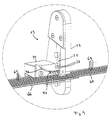
- FIG. 9 shows how using the crimping device according to the invention two FPC conductors 66 and 67 are connected together.
- the respective ones FPC conductors consist of an insulating film 68 with parallel thereto mutually arranged interconnects 69. These interconnects 69 are again with a very thin insulating plastic coating covered, which is not shown. Should two tracks be different FPC conductors 66, 67 are connected together, so are the FPC conductors 66, 67 one above the other in the working area of the crimping device arranged.
- the conductors 69 of the different FPC conductors are thus in Longitudinal direction to each other. However, they are still through the respective insulation isolated against each other.
- FIG. 11 A corresponding cut in this direction C is shown in FIG. 11. It is Here is a cross-sectional view perpendicular to the longitudinal direction superimposed interconnects 69 different FPC conductors 66, 67th As a result of the crimping process, the mandrel 56 penetrates the inside of the Base of the crimping element 51, the upper insulating layer of the conductor 69 of the upper FPC conductor 67, while the inward and backward bent legs 53, 54 penetrate the lower insulation of the lower FPC conductor 66 and contact the conductor 69. This is an electrical contact between the conductive traces 69 of lower and upper FPC conductors 66, 67 conditions.
Landscapes
- Engineering & Computer Science (AREA)
- Manufacturing & Machinery (AREA)
- Manufacturing Of Electrical Connectors (AREA)
- Absorbent Articles And Supports Therefor (AREA)
- Auxiliary Devices For And Details Of Packaging Control (AREA)
- Yarns And Mechanical Finishing Of Yarns Or Ropes (AREA)
Claims (12)
- Dispositif de sertissage avec au moins :caractérisé en ce queun cadre porteur en forme de plaque (12) ;une fente de guidage (21) présente dans le cadre porteur (12) pour la réception d'un poinçon de sertissage (25) ;une matrice de sertissage (24) ; etdes moyens d'entraínement (14, 15) présents sur le cadre porteur (12) ainsi que sur le poinçon de sertissage (25), par l'intermédiaire desquels le poinçon de sertissage (25) peut être déplacé en direction de la matrice de sertissage (24), respectivement éloigné de cette dernière,et en ce queune fente de travail (22) s'étendant transversalement par rapport à la fente de guidage (21) est prévue, dans laquelle débouche la fente de guidage (21), la fente de travail (22) s'étendant jusqu'à une arête frontale (18) du cadre porteur (12) ;la matrice de sertissage (24) se trouve dans une paroi de fente (23) de la fente de travail (22).
- Dispositif de sertissage selon la revendication 1, caractérisé en ce que les moyens d'entraínement sont des ouvertures (26, 31) pour la réception d'axes (14, 15) ou sont configurés comme des saillies.
- Dispositif de sertissage selon la revendication 1 ou 2, caractérisé en ce que le poinçon de sertissage (25) porte un serre-flanc (27) latéralement par rapport à lui.
- Dispositif de sertissage selon la revendication 3, caractérisé en ce que le serre-flanc (27) se trouve des deux côtés du poinçon de sertissage (25) vu dans la direction longitudinale de la fente de travail (22).
- Dispositif de sertissage selon la revendication 3 ou 4, caractérisé par un dispositif à ressort (44) agissant entre le poinçon de sertissage (25) et le serre-flanc (27), qui tend à avancer l'arête frontale du serre-flanc (27) tournée vers la matrice de sertissage (24) par rapport à l'arête frontale correspondante du poinçon de sertissage (25).
- Dispositif de sertissage selon la revendication 5, caractérisé en ce que le serre-flanc (27) comporte un trou oblong (28) s'étendant dans la direction longitudinale de la fente de guidage (21), qui accueille un axe (14) ou une saillie du poinçon de sertissage (25).
- Dispositif de sertissage selon l'une quelconque des revendications 1 à 6, caractérisé en ce que le cadre porteur (12) porte une unité d'alimentation (39) pour l'amenée des éléments de sertissage (51) à la matrice de sertissage (24).
- Dispositif de sertissage selon la revendication 7, caractérisé en ce que l'unité d'alimentation (39) transporte les éléments de sertissage (51) avec une base (52) et deux branches (53, 54) parallèles à celle-ci dans une direction qui se trouve perpendiculaire au plan sous-tendu par la base et les branches.
- Dispositif de sertissage selon l'une quelconque des revendications 3 à 8, caractérisé en ce que le serre-flanc (27) comporte une butée (64) pour positionner les éléments de sertissage (51) amenés au cadre porteur (12) par rapport à la matrice de sertissage (24).
- Dispositif de sertissage selon la revendication 9, caractérisé en ce que la butée (64) est configurée de telle sorte que seules les branches (53, 54) des éléments de sertissage (51) peuvent être guidés contre elle.
- Dispositif de sertissage selon l'une quelconque des revendications 7 à 10, caractérisé en ce que l'unité d'alimentation (39) comporte une surface de soutien (57) pour les éléments de sertissage (51), qui va jusqu'au passage du poinçon de sertissage (25) et en ce que les arêtes (61, 60) tournées l'une vers l'autre du poinçon de sertissage (25) et de la surface de soutien (57) forment un dispositif de coupe.
- Dispositif de sertissage selon l'une quelconque des revendications 1 à 11, caractérisé en ce qu'il comporte une pince (1) avec deux mors de travail (2, 3) dont un respectivement entraíne le cadre porteur (12), respectivement le poinçon de sertissage (25) par l'intermédiaire des moyens d'entraínement (14, 15) respectifs.
Applications Claiming Priority (2)
| Application Number | Priority Date | Filing Date | Title |
|---|---|---|---|
| DE20205557U | 2002-04-10 | ||
| DE20205557U DE20205557U1 (de) | 2002-04-10 | 2002-04-10 | Crimpvorrichtung |
Publications (2)
| Publication Number | Publication Date |
|---|---|
| EP1353420A1 EP1353420A1 (fr) | 2003-10-15 |
| EP1353420B1 true EP1353420B1 (fr) | 2005-03-23 |
Family
ID=7969875
Family Applications (1)
| Application Number | Title | Priority Date | Filing Date |
|---|---|---|---|
| EP03008181A Expired - Lifetime EP1353420B1 (fr) | 2002-04-10 | 2003-04-08 | Dispositif de sertissage |
Country Status (4)
| Country | Link |
|---|---|
| EP (1) | EP1353420B1 (fr) |
| AT (1) | ATE291786T1 (fr) |
| DE (2) | DE20205557U1 (fr) |
| ES (1) | ES2238649T3 (fr) |
Cited By (16)
| Publication number | Priority date | Publication date | Assignee | Title |
|---|---|---|---|---|
| DE102007014903B3 (de) * | 2007-03-26 | 2008-07-17 | Rennsteig Werkzeuge Gmbh | Auswechselbares Gesenk für Zangen, Zange mit einem solchen Gesenk und Aufbewahrungsvorrichtung |
| DE102009002155A1 (de) | 2009-04-02 | 2010-10-07 | Rennsteig Werkzeuge Gmbh | Verbindung zur lösbaren Befestigung eines Gesenkes oder einer Positioniereinrichtung an einer Crimpzange sowie Positioniereinrichtung und Crimpzange mit einer solchen Verbindung |
| US8640521B2 (en) | 2007-07-12 | 2014-02-04 | Sorin Group Italia S.R.L. | Expandable prosthetic valve crimping device |
| US8715207B2 (en) | 2009-03-19 | 2014-05-06 | Sorin Group Italia S.R.L. | Universal valve annulus sizing device |
| US9149207B2 (en) | 2009-03-26 | 2015-10-06 | Sorin Group Usa, Inc. | Annuloplasty sizers for minimally invasive procedures |
| US9161836B2 (en) | 2011-02-14 | 2015-10-20 | Sorin Group Italia S.R.L. | Sutureless anchoring device for cardiac valve prostheses |
| US9248017B2 (en) | 2010-05-21 | 2016-02-02 | Sorin Group Italia S.R.L. | Support device for valve prostheses and corresponding kit |
| US9289289B2 (en) | 2011-02-14 | 2016-03-22 | Sorin Group Italia S.R.L. | Sutureless anchoring device for cardiac valve prostheses |
| US9486313B2 (en) | 2005-02-10 | 2016-11-08 | Sorin Group Italia S.R.L. | Cardiac valve prosthesis |
| US9848981B2 (en) | 2007-10-12 | 2017-12-26 | Mayo Foundation For Medical Education And Research | Expandable valve prosthesis with sealing mechanism |
| US9867695B2 (en) | 2004-03-03 | 2018-01-16 | Sorin Group Italia S.R.L. | Minimally-invasive cardiac-valve prosthesis |
| US10098733B2 (en) | 2008-12-23 | 2018-10-16 | Sorin Group Italia S.R.L. | Expandable prosthetic valve having anchoring appendages |
| US11504231B2 (en) | 2018-05-23 | 2022-11-22 | Corcym S.R.L. | Cardiac valve prosthesis |
| US11819406B2 (en) | 2018-05-23 | 2023-11-21 | Corcym S.R.L. | Loading system for an implantable prosthesis and related loading method |
| US11992397B2 (en) | 2018-05-23 | 2024-05-28 | Corcym S.R.L. | Holder for heart valve prosthesis, a storage arrangement for a heart valve prosthesis, and a crimping kit and method |
| US12083013B2 (en) | 2017-10-07 | 2024-09-10 | Corcym S.R.L. | Bendable cardiac surgery instruments |
Families Citing this family (3)
| Publication number | Priority date | Publication date | Assignee | Title |
|---|---|---|---|---|
| DE202004005803U1 (de) * | 2004-04-08 | 2005-09-29 | Schleuniger Holding Ag | Kontaktierungsvorrichtung für einen Folienleiter |
| DE102005024878B3 (de) * | 2005-05-31 | 2006-12-14 | Tyco Electronics Amp Gmbh | Anschlagvorrichtung zum Anschlagen von elektrischen Kontaktelementen |
| EP2229921B1 (fr) | 2007-07-12 | 2014-11-12 | Sorin Group Italia S.r.l. | Dispositif de gaufrage de valve prosthétique extensible |
Family Cites Families (12)
| Publication number | Priority date | Publication date | Assignee | Title |
|---|---|---|---|---|
| BE533170A (fr) * | 1953-11-10 | |||
| GB1225326A (fr) | 1968-05-31 | 1971-03-17 | ||
| US3553836A (en) | 1969-05-21 | 1971-01-12 | Amp Inc | Method and apparatus for terminating cable |
| US3710610A (en) * | 1970-06-05 | 1973-01-16 | Bunker Ramo | Wire terminal crimping tool |
| BE795006A (fr) | 1972-02-08 | 1973-08-06 | Amp Inc | Appareil de sertissage de cosses sur les conducteurs electriques d'un cable plat |
| GB1432843A (en) * | 1973-04-04 | 1976-04-22 | Rommel Reiner | Tongs |
| US4411484A (en) | 1980-02-19 | 1983-10-25 | Amp Incorporated | Terminations for flat cable |
| US4831722A (en) | 1981-10-26 | 1989-05-23 | Burndy Corporation | Apparatus and method for installing electrical connectors on flat conductor cable |
| US5125259A (en) | 1991-05-08 | 1992-06-30 | Amp Incorporated | Hand tooling for forming electrical contact elements |
| DE19713580C2 (de) * | 1997-04-02 | 1999-12-30 | Wezag Gmbh | Preßzange zum Verformen eines Werkstückes |
| US5870925A (en) * | 1997-06-27 | 1999-02-16 | The Whitaker Corporation | Hand tool crimping a terminal onto a conductor |
| DE29910927U1 (de) | 1999-06-22 | 1999-09-02 | Connectool GmbH & Co., 32758 Detmold | Werkzeugmodul |
-
2002
- 2002-04-10 DE DE20205557U patent/DE20205557U1/de not_active Expired - Lifetime
-
2003
- 2003-04-08 AT AT03008181T patent/ATE291786T1/de not_active IP Right Cessation
- 2003-04-08 DE DE50300375T patent/DE50300375D1/de not_active Expired - Lifetime
- 2003-04-08 ES ES03008181T patent/ES2238649T3/es not_active Expired - Lifetime
- 2003-04-08 EP EP03008181A patent/EP1353420B1/fr not_active Expired - Lifetime
Cited By (21)
| Publication number | Priority date | Publication date | Assignee | Title |
|---|---|---|---|---|
| US9867695B2 (en) | 2004-03-03 | 2018-01-16 | Sorin Group Italia S.R.L. | Minimally-invasive cardiac-valve prosthesis |
| US9895223B2 (en) | 2005-02-10 | 2018-02-20 | Sorin Group Italia S.R.L. | Cardiac valve prosthesis |
| US9486313B2 (en) | 2005-02-10 | 2016-11-08 | Sorin Group Italia S.R.L. | Cardiac valve prosthesis |
| US9403264B2 (en) | 2007-03-26 | 2016-08-02 | Rennsteig Werkzeuge Gmbh | Replaceable die for pliers, pliers having such a die, and storage fixture |
| DE102007014903B3 (de) * | 2007-03-26 | 2008-07-17 | Rennsteig Werkzeuge Gmbh | Auswechselbares Gesenk für Zangen, Zange mit einem solchen Gesenk und Aufbewahrungsvorrichtung |
| US8640521B2 (en) | 2007-07-12 | 2014-02-04 | Sorin Group Italia S.R.L. | Expandable prosthetic valve crimping device |
| US10966823B2 (en) | 2007-10-12 | 2021-04-06 | Sorin Group Italia S.R.L. | Expandable valve prosthesis with sealing mechanism |
| US9848981B2 (en) | 2007-10-12 | 2017-12-26 | Mayo Foundation For Medical Education And Research | Expandable valve prosthesis with sealing mechanism |
| US10098733B2 (en) | 2008-12-23 | 2018-10-16 | Sorin Group Italia S.R.L. | Expandable prosthetic valve having anchoring appendages |
| US9918841B2 (en) | 2009-03-19 | 2018-03-20 | Sorin Group Italia S.R.L. | Universal valve annulus sizing device |
| US8715207B2 (en) | 2009-03-19 | 2014-05-06 | Sorin Group Italia S.R.L. | Universal valve annulus sizing device |
| US9149207B2 (en) | 2009-03-26 | 2015-10-06 | Sorin Group Usa, Inc. | Annuloplasty sizers for minimally invasive procedures |
| DE102009002155A1 (de) | 2009-04-02 | 2010-10-07 | Rennsteig Werkzeuge Gmbh | Verbindung zur lösbaren Befestigung eines Gesenkes oder einer Positioniereinrichtung an einer Crimpzange sowie Positioniereinrichtung und Crimpzange mit einer solchen Verbindung |
| US9248017B2 (en) | 2010-05-21 | 2016-02-02 | Sorin Group Italia S.R.L. | Support device for valve prostheses and corresponding kit |
| US9161836B2 (en) | 2011-02-14 | 2015-10-20 | Sorin Group Italia S.R.L. | Sutureless anchoring device for cardiac valve prostheses |
| US9289289B2 (en) | 2011-02-14 | 2016-03-22 | Sorin Group Italia S.R.L. | Sutureless anchoring device for cardiac valve prostheses |
| US12083013B2 (en) | 2017-10-07 | 2024-09-10 | Corcym S.R.L. | Bendable cardiac surgery instruments |
| US11504231B2 (en) | 2018-05-23 | 2022-11-22 | Corcym S.R.L. | Cardiac valve prosthesis |
| US11819406B2 (en) | 2018-05-23 | 2023-11-21 | Corcym S.R.L. | Loading system for an implantable prosthesis and related loading method |
| US11969341B2 (en) | 2018-05-23 | 2024-04-30 | Corcym S.R.L. | Cardiac valve prosthesis |
| US11992397B2 (en) | 2018-05-23 | 2024-05-28 | Corcym S.R.L. | Holder for heart valve prosthesis, a storage arrangement for a heart valve prosthesis, and a crimping kit and method |
Also Published As
| Publication number | Publication date |
|---|---|
| ES2238649T3 (es) | 2005-09-01 |
| EP1353420A1 (fr) | 2003-10-15 |
| ATE291786T1 (de) | 2005-04-15 |
| DE50300375D1 (de) | 2005-04-28 |
| DE20205557U1 (de) | 2002-07-04 |
Similar Documents
| Publication | Publication Date | Title |
|---|---|---|
| EP1353420B1 (fr) | Dispositif de sertissage | |
| DE2704540C2 (fr) | ||
| DE2820690C2 (de) | Vorrichtung zum Anschlagen einer elektrischen Anschlußklemme an einen Leiterendabschnitt | |
| DE2356140C2 (de) | Vorrichtung zur Befestigung von wenigstens einem zuvor auf einem dünnen Plastikfilm montierten integrierten Schaltungsplättchen | |
| DE1027746B (de) | Maschine zum Montieren von elektrischen Bauelementen | |
| DE1922524A1 (de) | Den Zwecken der Abisolierung dienende Zusatzanordnung fuer eine Presse | |
| DE2018901B2 (de) | Werkzeug zum Andrücken eines im Querschnitt im wesentlichen U-förmigen elektrischen Verbinders an einen Leiter | |
| DE19603281C2 (de) | Vorrichtung zur Herstellung von unter Preßsitz zusammengefügten elektrischen Kabelbäumen und zugehöriges Verfahren | |
| EP3563959A1 (fr) | Dispositif de sciage | |
| DE1590003A1 (de) | Methode und Geraet zum Verlaschen von Draehten | |
| DE2024821B2 (de) | Vorrichtung zum Anschließen von elektrischen AnschluBteilen an die Flachleiter eines isolierten Flachbandkabels | |
| DE1615659C3 (de) | Verfahren und Vorrichtung zum elektrischen Verbinden einzelner Leitungsdrähte einer Gruppe von Leitugsdrähten | |
| DE2625915A1 (de) | Elektrische kontakte und verfahren zu ihrer herstellung | |
| DE2641373B2 (de) | Verfahren und Vorrichtung zum Verbinden der Bandenden eines Kunststoffbandes | |
| DE202009001625U1 (de) | Vereinzelungsvorrichtung zum Abscheren von an einem Vorratsband aufgereihten Werkstücken | |
| DE2360947B2 (de) | Vorrichtung zum Ausrichten einer Gruppe von Kuppelgliedern einer ReißverschluBkette | |
| DE102007032584B4 (de) | Vorrichtung zum Schweißen einer Litze an einen Kontakt | |
| DE3586837T2 (de) | Vorrichtung zum zusammensetzen von zweiteiligen steckerverbindern. | |
| DE3703686C1 (de) | Schweissvorrichtung | |
| DE3933316A1 (de) | Verfahren und vorrichtung zum verbinden eines elektrischen steckverbinders mit einem kabel | |
| DE2336233A1 (de) | Verfahren und vorrichtung zur herstellung von metallstangen mit gezahnten kanten | |
| EP0390760A2 (fr) | Appareil pour attacher des contacts aux conducteurs électriques | |
| DE2628519C3 (de) | Verfahren und Vorrichtung zur Herstellung der aus Drähten bestehenden Verbindungen zwischen den Anschlußstellen eines Bauelementes und Anschluß- oder Kontaktelementen | |
| DE2062759A1 (de) | Maschine zum gleichzeitigen Anschlagen mehrerer Verbinder an nebenemanderliegende Leiterenden | |
| DE29910927U1 (de) | Werkzeugmodul |
Legal Events
| Date | Code | Title | Description |
|---|---|---|---|
| PUAI | Public reference made under article 153(3) epc to a published international application that has entered the european phase |
Free format text: ORIGINAL CODE: 0009012 |
|
| AK | Designated contracting states |
Kind code of ref document: A1 Designated state(s): AT BE BG CH CY CZ DE DK EE ES FI FR GB GR HU IE IT LI LU MC NL PT SE SI SK TR |
|
| AX | Request for extension of the european patent |
Extension state: AL LT LV MK RO |
|
| 17P | Request for examination filed |
Effective date: 20031222 |
|
| 17Q | First examination report despatched |
Effective date: 20040220 |
|
| AKX | Designation fees paid |
Designated state(s): AT BE BG CH CY CZ DE DK EE ES FI FR GB GR HU IE IT LI LU MC NL PT SE SI SK TR |
|
| GRAP | Despatch of communication of intention to grant a patent |
Free format text: ORIGINAL CODE: EPIDOSNIGR1 |
|
| GRAS | Grant fee paid |
Free format text: ORIGINAL CODE: EPIDOSNIGR3 |
|
| GRAA | (expected) grant |
Free format text: ORIGINAL CODE: 0009210 |
|
| AK | Designated contracting states |
Kind code of ref document: B1 Designated state(s): AT BE BG CH CY CZ DE DK EE ES FI FR GB GR HU IE IT LI LU MC NL PT SE SI SK TR |
|
| PG25 | Lapsed in a contracting state [announced via postgrant information from national office to epo] |
Ref country code: FI Free format text: LAPSE BECAUSE OF FAILURE TO SUBMIT A TRANSLATION OF THE DESCRIPTION OR TO PAY THE FEE WITHIN THE PRESCRIBED TIME-LIMIT Effective date: 20050323 Ref country code: SI Free format text: LAPSE BECAUSE OF FAILURE TO SUBMIT A TRANSLATION OF THE DESCRIPTION OR TO PAY THE FEE WITHIN THE PRESCRIBED TIME-LIMIT Effective date: 20050323 Ref country code: SK Free format text: LAPSE BECAUSE OF FAILURE TO SUBMIT A TRANSLATION OF THE DESCRIPTION OR TO PAY THE FEE WITHIN THE PRESCRIBED TIME-LIMIT Effective date: 20050323 Ref country code: EE Free format text: LAPSE BECAUSE OF FAILURE TO SUBMIT A TRANSLATION OF THE DESCRIPTION OR TO PAY THE FEE WITHIN THE PRESCRIBED TIME-LIMIT Effective date: 20050323 Ref country code: NL Free format text: LAPSE BECAUSE OF FAILURE TO SUBMIT A TRANSLATION OF THE DESCRIPTION OR TO PAY THE FEE WITHIN THE PRESCRIBED TIME-LIMIT Effective date: 20050323 Ref country code: IE Free format text: LAPSE BECAUSE OF FAILURE TO SUBMIT A TRANSLATION OF THE DESCRIPTION OR TO PAY THE FEE WITHIN THE PRESCRIBED TIME-LIMIT Effective date: 20050323 Ref country code: TR Free format text: LAPSE BECAUSE OF FAILURE TO SUBMIT A TRANSLATION OF THE DESCRIPTION OR TO PAY THE FEE WITHIN THE PRESCRIBED TIME-LIMIT Effective date: 20050323 |
|
| REG | Reference to a national code |
Ref country code: GB Ref legal event code: FG4D Free format text: NOT ENGLISH |
|
| REG | Reference to a national code |
Ref country code: CH Ref legal event code: EP |
|
| PG25 | Lapsed in a contracting state [announced via postgrant information from national office to epo] |
Ref country code: LU Free format text: LAPSE BECAUSE OF NON-PAYMENT OF DUE FEES Effective date: 20050408 Ref country code: AT Free format text: LAPSE BECAUSE OF NON-PAYMENT OF DUE FEES Effective date: 20050408 Ref country code: CY Free format text: LAPSE BECAUSE OF FAILURE TO SUBMIT A TRANSLATION OF THE DESCRIPTION OR TO PAY THE FEE WITHIN THE PRESCRIBED TIME-LIMIT Effective date: 20050408 |
|
| REG | Reference to a national code |
Ref country code: IE Ref legal event code: FG4D Free format text: GERMAN |
|
| REF | Corresponds to: |
Ref document number: 50300375 Country of ref document: DE Date of ref document: 20050428 Kind code of ref document: P |
|
| PG25 | Lapsed in a contracting state [announced via postgrant information from national office to epo] |
Ref country code: BE Free format text: LAPSE BECAUSE OF NON-PAYMENT OF DUE FEES Effective date: 20050430 Ref country code: MC Free format text: LAPSE BECAUSE OF NON-PAYMENT OF DUE FEES Effective date: 20050430 |
|
| GBT | Gb: translation of ep patent filed (gb section 77(6)(a)/1977) |
Effective date: 20050526 |
|
| PG25 | Lapsed in a contracting state [announced via postgrant information from national office to epo] |
Ref country code: DK Free format text: LAPSE BECAUSE OF FAILURE TO SUBMIT A TRANSLATION OF THE DESCRIPTION OR TO PAY THE FEE WITHIN THE PRESCRIBED TIME-LIMIT Effective date: 20050623 Ref country code: BG Free format text: LAPSE BECAUSE OF FAILURE TO SUBMIT A TRANSLATION OF THE DESCRIPTION OR TO PAY THE FEE WITHIN THE PRESCRIBED TIME-LIMIT Effective date: 20050623 Ref country code: GR Free format text: LAPSE BECAUSE OF FAILURE TO SUBMIT A TRANSLATION OF THE DESCRIPTION OR TO PAY THE FEE WITHIN THE PRESCRIBED TIME-LIMIT Effective date: 20050623 |
|
| PG25 | Lapsed in a contracting state [announced via postgrant information from national office to epo] |
Ref country code: HU Free format text: LAPSE BECAUSE OF FAILURE TO SUBMIT A TRANSLATION OF THE DESCRIPTION OR TO PAY THE FEE WITHIN THE PRESCRIBED TIME-LIMIT Effective date: 20050624 |
|
| REG | Reference to a national code |
Ref country code: SE Ref legal event code: TRGR |
|
| NLV1 | Nl: lapsed or annulled due to failure to fulfill the requirements of art. 29p and 29m of the patents act | ||
| REG | Reference to a national code |
Ref country code: ES Ref legal event code: FG2A Ref document number: 2238649 Country of ref document: ES Kind code of ref document: T3 |
|
| PG25 | Lapsed in a contracting state [announced via postgrant information from national office to epo] |
Ref country code: PT Free format text: LAPSE BECAUSE OF FAILURE TO SUBMIT A TRANSLATION OF THE DESCRIPTION OR TO PAY THE FEE WITHIN THE PRESCRIBED TIME-LIMIT Effective date: 20050907 |
|
| REG | Reference to a national code |
Ref country code: IE Ref legal event code: FD4D |
|
| BERE | Be: lapsed |
Owner name: WEIDMULLER INTERFACE G.M.B.H. & CO. Effective date: 20050430 |
|
| ET | Fr: translation filed | ||
| PLBE | No opposition filed within time limit |
Free format text: ORIGINAL CODE: 0009261 |
|
| STAA | Information on the status of an ep patent application or granted ep patent |
Free format text: STATUS: NO OPPOSITION FILED WITHIN TIME LIMIT |
|
| 26N | No opposition filed |
Effective date: 20051227 |
|
| REG | Reference to a national code |
Ref country code: CH Ref legal event code: PL |
|
| BERE | Be: lapsed |
Owner name: WEIDMULLER INTERFACE G.M.B.H. & CO. Effective date: 20050430 |
|
| PG25 | Lapsed in a contracting state [announced via postgrant information from national office to epo] |
Ref country code: LI Free format text: LAPSE BECAUSE OF NON-PAYMENT OF DUE FEES Effective date: 20070430 Ref country code: CH Free format text: LAPSE BECAUSE OF NON-PAYMENT OF DUE FEES Effective date: 20070430 |
|
| PGFP | Annual fee paid to national office [announced via postgrant information from national office to epo] |
Ref country code: ES Payment date: 20090422 Year of fee payment: 7 |
|
| PGFP | Annual fee paid to national office [announced via postgrant information from national office to epo] |
Ref country code: CZ Payment date: 20090401 Year of fee payment: 7 Ref country code: FR Payment date: 20090414 Year of fee payment: 7 Ref country code: IT Payment date: 20090422 Year of fee payment: 7 Ref country code: SE Payment date: 20090416 Year of fee payment: 7 |
|
| PGFP | Annual fee paid to national office [announced via postgrant information from national office to epo] |
Ref country code: GB Payment date: 20090421 Year of fee payment: 7 |
|
| EUG | Se: european patent has lapsed | ||
| GBPC | Gb: european patent ceased through non-payment of renewal fee |
Effective date: 20100408 |
|
| REG | Reference to a national code |
Ref country code: FR Ref legal event code: ST Effective date: 20101230 |
|
| PG25 | Lapsed in a contracting state [announced via postgrant information from national office to epo] |
Ref country code: CZ Free format text: LAPSE BECAUSE OF NON-PAYMENT OF DUE FEES Effective date: 20100408 |
|
| PG25 | Lapsed in a contracting state [announced via postgrant information from national office to epo] |
Ref country code: IT Free format text: LAPSE BECAUSE OF NON-PAYMENT OF DUE FEES Effective date: 20100408 Ref country code: GB Free format text: LAPSE BECAUSE OF NON-PAYMENT OF DUE FEES Effective date: 20100408 |
|
| REG | Reference to a national code |
Ref country code: ES Ref legal event code: FD2A Effective date: 20110711 |
|
| PG25 | Lapsed in a contracting state [announced via postgrant information from national office to epo] |
Ref country code: ES Free format text: LAPSE BECAUSE OF NON-PAYMENT OF DUE FEES Effective date: 20110629 |
|
| PG25 | Lapsed in a contracting state [announced via postgrant information from national office to epo] |
Ref country code: ES Free format text: LAPSE BECAUSE OF NON-PAYMENT OF DUE FEES Effective date: 20100409 |
|
| PG25 | Lapsed in a contracting state [announced via postgrant information from national office to epo] |
Ref country code: FR Free format text: LAPSE BECAUSE OF NON-PAYMENT OF DUE FEES Effective date: 20100430 |
|
| PG25 | Lapsed in a contracting state [announced via postgrant information from national office to epo] |
Ref country code: SE Free format text: LAPSE BECAUSE OF NON-PAYMENT OF DUE FEES Effective date: 20100409 |
|
| PGFP | Annual fee paid to national office [announced via postgrant information from national office to epo] |
Ref country code: DE Payment date: 20130419 Year of fee payment: 11 |
|
| REG | Reference to a national code |
Ref country code: DE Ref legal event code: R119 Ref document number: 50300375 Country of ref document: DE |
|
| REG | Reference to a national code |
Ref country code: DE Ref legal event code: R119 Ref document number: 50300375 Country of ref document: DE Effective date: 20141101 |
|
| PG25 | Lapsed in a contracting state [announced via postgrant information from national office to epo] |
Ref country code: DE Free format text: LAPSE BECAUSE OF NON-PAYMENT OF DUE FEES Effective date: 20141101 |