EP1336816A2 - Tête, appareil et méthode pour le contrôle des dimensions Linéaires de pièces mécaniques - Google Patents
Tête, appareil et méthode pour le contrôle des dimensions Linéaires de pièces mécaniques Download PDFInfo
- Publication number
- EP1336816A2 EP1336816A2 EP03008236A EP03008236A EP1336816A2 EP 1336816 A2 EP1336816 A2 EP 1336816A2 EP 03008236 A EP03008236 A EP 03008236A EP 03008236 A EP03008236 A EP 03008236A EP 1336816 A2 EP1336816 A2 EP 1336816A2
- Authority
- EP
- European Patent Office
- Prior art keywords
- arm
- head
- support
- coupling
- transducer
- Prior art date
- Legal status (The legal status is an assumption and is not a legal conclusion. Google has not performed a legal analysis and makes no representation as to the accuracy of the status listed.)
- Granted
Links
Images


Classifications
-
- G—PHYSICS
- G01—MEASURING; TESTING
- G01B—MEASURING LENGTH, THICKNESS OR SIMILAR LINEAR DIMENSIONS; MEASURING ANGLES; MEASURING AREAS; MEASURING IRREGULARITIES OF SURFACES OR CONTOURS
- G01B5/00—Measuring arrangements characterised by the use of mechanical techniques
- G01B5/0002—Arrangements for supporting, fixing or guiding the measuring instrument or the object to be measured
- G01B5/0004—Supports
-
- B—PERFORMING OPERATIONS; TRANSPORTING
- B24—GRINDING; POLISHING
- B24B—MACHINES, DEVICES, OR PROCESSES FOR GRINDING OR POLISHING; DRESSING OR CONDITIONING OF ABRADING SURFACES; FEEDING OF GRINDING, POLISHING, OR LAPPING AGENTS
- B24B49/00—Measuring or gauging equipment for controlling the feed movement of the grinding tool or work; Arrangements of indicating or measuring equipment, e.g. for indicating the start of the grinding operation
- B24B49/02—Measuring or gauging equipment for controlling the feed movement of the grinding tool or work; Arrangements of indicating or measuring equipment, e.g. for indicating the start of the grinding operation according to the instantaneous size and required size of the workpiece acted upon, the measuring or gauging being continuous or intermittent
- B24B49/04—Measuring or gauging equipment for controlling the feed movement of the grinding tool or work; Arrangements of indicating or measuring equipment, e.g. for indicating the start of the grinding operation according to the instantaneous size and required size of the workpiece acted upon, the measuring or gauging being continuous or intermittent involving measurement of the workpiece at the place of grinding during grinding operation
-
- G—PHYSICS
- G01—MEASURING; TESTING
- G01B—MEASURING LENGTH, THICKNESS OR SIMILAR LINEAR DIMENSIONS; MEASURING ANGLES; MEASURING AREAS; MEASURING IRREGULARITIES OF SURFACES OR CONTOURS
- G01B3/00—Measuring instruments characterised by the use of mechanical techniques
- G01B3/002—Details
- G01B3/008—Arrangements for controlling the measuring force
-
- G—PHYSICS
- G01—MEASURING; TESTING
- G01B—MEASURING LENGTH, THICKNESS OR SIMILAR LINEAR DIMENSIONS; MEASURING ANGLES; MEASURING AREAS; MEASURING IRREGULARITIES OF SURFACES OR CONTOURS
- G01B7/00—Measuring arrangements characterised by the use of electric or magnetic techniques
- G01B7/001—Constructional details of gauge heads
-
- G—PHYSICS
- G01—MEASURING; TESTING
- G01B—MEASURING LENGTH, THICKNESS OR SIMILAR LINEAR DIMENSIONS; MEASURING ANGLES; MEASURING AREAS; MEASURING IRREGULARITIES OF SURFACES OR CONTOURS
- G01B7/00—Measuring arrangements characterised by the use of electric or magnetic techniques
- G01B7/004—Measuring arrangements characterised by the use of electric or magnetic techniques for measuring coordinates of points
- G01B7/008—Measuring arrangements characterised by the use of electric or magnetic techniques for measuring coordinates of points using coordinate measuring machines
- G01B7/012—Contact-making feeler heads therefor
-
- G—PHYSICS
- G01—MEASURING; TESTING
- G01B—MEASURING LENGTH, THICKNESS OR SIMILAR LINEAR DIMENSIONS; MEASURING ANGLES; MEASURING AREAS; MEASURING IRREGULARITIES OF SURFACES OR CONTOURS
- G01B7/00—Measuring arrangements characterised by the use of electric or magnetic techniques
- G01B7/12—Measuring arrangements characterised by the use of electric or magnetic techniques for measuring diameters
-
- G—PHYSICS
- G01—MEASURING; TESTING
- G01B—MEASURING LENGTH, THICKNESS OR SIMILAR LINEAR DIMENSIONS; MEASURING ANGLES; MEASURING AREAS; MEASURING IRREGULARITIES OF SURFACES OR CONTOURS
- G01B7/00—Measuring arrangements characterised by the use of electric or magnetic techniques
- G01B7/34—Measuring arrangements characterised by the use of electric or magnetic techniques for measuring roughness or irregularity of surfaces
-
- G—PHYSICS
- G01—MEASURING; TESTING
- G01D—MEASURING NOT SPECIALLY ADAPTED FOR A SPECIFIC VARIABLE; ARRANGEMENTS FOR MEASURING TWO OR MORE VARIABLES NOT COVERED IN A SINGLE OTHER SUBCLASS; TARIFF METERING APPARATUS; MEASURING OR TESTING NOT OTHERWISE PROVIDED FOR
- G01D3/00—Indicating or recording apparatus with provision for the special purposes referred to in the subgroups
- G01D3/02—Indicating or recording apparatus with provision for the special purposes referred to in the subgroups with provision for altering or correcting the law of variation
- G01D3/022—Indicating or recording apparatus with provision for the special purposes referred to in the subgroups with provision for altering or correcting the law of variation having an ideal characteristic, map or correction data stored in a digital memory
Definitions
- the present invention relates to heads for the linear dimension checking of a mechanical piece, including a support structure with a casing that defines a recess and a longitudinal geometric axis, an arm-set, movable with respect to the support structure, with an arm, at least partially housed in the recess, and a feeler, coupled to the arm, for touching a surface of the mechanical piece to be checked, a fulcrum, located between the arm and the support structure, for enabling displacements of the arm with respect to the support structure about a transversal axis, thrust devices located between the arm and the support structure for urging the feeler towards the surface of the piece to be checked, and a transducer, coupled to the arm and the support structure, for providing signals depending on the position of the arm with respect to the support structure.
- the invention also relates to an apparatus for the linear dimension checking of mechanical pieces, including at least a head for the linear dimension checking of mechanical pieces and a support and reference system, with a substantially stationary structure, for supporting and locating the head in a determinate checking position.
- the invention relates to a method for the linear dimension checking of a mechanical piece, by means of an apparatus with at least a gauging head, including a zero setting phase carried out on a master piece, for displacing the head to a definite checking position, and a checking phase.
- the invention relates to an inductive type transducer for use in heads for the linear dimension checking with a support structure and an arm, movable with respect to the support structure, for generating electric signals depending on the position of the arm with respect to the support structure, the transducer including windings and a core, made from ferromagnetic material, housed within the windings and movable with respect to them, the transducer further including a hollow support with a first housing and a spool, arranged in the first housing, with annular seats for the windings.
- the invention also relates to an apparatus for the linear dimension checking of a mechanical piece, with a gauging head for cooperating with the piece, a transducer at least partially included in the gauging head for generating electric signals indicative of the dimensions of the piece, a processing unit, and electric coupling means between the head and the processing unit.
- the transducer devices of the known heads for example of the linear voltage differential transformer, or half-bridge type, with reciprocally movable windings and core have a linear performance in an extremely limited area of displacement between the core and the windings, hence permitting limited measuring ranges.
- these transducer devices have a structure that is delicate and particularly sensitive to temperature variations that cause undesired drifts, known as "thermal drifts", in the course of the operation of the heads.
- the known heads also include cables with electric wires that enable the sending of signals from the associated transducers to the processing units, and connectors at the free end of the cables.
- the connectors of the known heads have elements intended to be coupled to each other, for example, by means of a threaded coupling, that requires particular care on behalf of the operator for achieving the appropriate locking and sealing.
- apparatuses comprising frames for supporting these heads, for example, supports for supporting and referring a pair of heads in applications for the diameter checking.
- the heads can be coupled to the support in an adjustable way, both reciprocally and with respect to the support.
- Apparatuses of this type are utilized, for example, for the diameter checking of pieces in the course of the machining in machine tools, more specifically, in grinding machines.
- the component parts of the apparatus more specifically the gauging heads, can be subject to accidental and undesirable collisions, frequently occurring especially in the workshop environment where there are applications of the "in-process" type. These collisions can alter the checking position of the heads, besides cause damage to the actual heads.
- An object of the present invention is to provide gauging or measuring heads for the linear dimension checking of mechanical pieces that guarantee high standards of repeatability and accuracy, are particularly reliable, versatile and inexpensive, hence overcome the disadvantages of the known heads. It is another object of the invention to provide component parts for gauging heads, in particular transducers and connectors, that contribute to improve the performance of the heads and reduce their manufacturing costs, and make their use extremely simple and flexible.
- Yet another object of the invention is to provide checking apparatuses that utilize gauging or measuring heads that, while guaranteeing high standards of repeatability and accuracy, are particularly safe and flexible in use, and need only easy and quick set-up operations.
- a still further object of the invention is to provide a checking apparatus with at least a gauging or measuring head and means for the connection to a processing unit that are particularly reliable, compact and can be easily and quickly replaced.
- the heads, the apparatuses, the component parts and the method according to the invention provide particular advantages, as described in the following description.
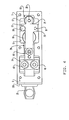
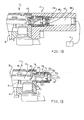
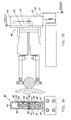
- the head shown in figures 1-6 more specifically a gauging head 1, comprises a support and protection structure with a steel casing 3 , substantially of a prismatic shape, in particular a parallelepipedon shape, that defines a longitudinal geometric axis.
- the casing 3 has a recess 12 , with a substantially longitudinal arrangement, and a front face 5 , an upper face 6 , a lower face 7 and a rear face 8 with holes and openings for access to the recess 12 .
- an elongate opening 15 is defined in the upper face 6
- a central opening 16 is defined in the front face 5 .
- a movable arm-set comprises an arm 20 that is partially housed in recess 12 of casing 3 and arranged substantially parallel to the longitudinal geometric axis of casing 3 .
- the arm 20 includes a first end portion 21 , located within casing 3 , with two transversal wings 22 and 23 (shown in figure 4), an intermediate portion 24 and a second end portion 25 , that traverses the central opening 16 of the front face 5 and carries, at the exterior of the casing 3 , a support 26 for a feeler 27 .
- a fulcrum 30 (also detailedly shown in an enlarged scale in figure 6) is coupled to casing 3 and movable arm 20 for enabling limited rotational displacements of arm 20 about a transversal axis. It comprises a deformable element consisting of three steel laminae 31 , 32 and 33 , permanently secured to two blocks 34 and 35 made of, for example, a zinc alloy. Die-casting is a process adopted for obtaining this permanent fixing between elements made of different materials, even though there can be foreseen other types of processes (for example, welding).
- the die-casting process for permanently fixing the laminae 31 , 32 and 33 to blocks 34 and 35 is achieved by inserting the laminae 31 , 32 and 33 in a die in which there is thereafter injected the melted material required for achieving the blocks 34 and 35 .
- the laminae 31 , 32 and 33 remain fixed to this material once it cools down.
- the laminae 31 , 32 and 33 may define holes - in the areas intended to remain immersed in the melted material - that furtherly guarantee the fixing stability.
- the two blocks 34 and 35 are substantially parallel with respect to each other and the laminae 31 , 32 and 33 form, for example, 45 degree angles with blocks 34 and 35.
- the laminae 31 and 33 are substantially coplanar, whereas lamina 32 forms an angle of approximately 90 degrees with the other two laminae 31 and 33.
- the laminae 31, 33 on the one side, and 32 lie in two planes (for example, two mutually perpendicular planes) of a sheaf of planes defined by a straight line that represents the axis of rotation of arm 20 .
- Block 34 is coupled to the intermediate portion 24 of arm 20 by means of two screws 40 , while block 35 is coupled to an inner surface of casing 3 at a position corresponding to face 7 , by means of two other screws 41 (shown in figure 5).
- Block 34 shown in figures 2 and 6, is so shaped that the portion for the coupling to arm 20 has a quite limited extension in a longitudinal direction, thereby ensuring a better performance of fulcrum 30 by minimizing the transmission of strains from arm 20 to fulcrum 30 .
- fulcrum 30 enable arm 20 to perform limited but accurate rotation displacements about the formerly mentioned rotation axis, that is perpendicular to the longitudinal geometric axis of casing 3 and parallel to the upper and the lower faces 6 and 7 , respectively.
- Mechanic limiting devices comprise limit-stop elements fixed in recess 12 of casing 3 , adapted for cooperating with the upper and the lower surfaces of the transversal wings 22 and 23 , respectively, for limiting the rotation displacements of arm 20 in both directions. More specifically, a screw 50 is screwed into recess 12 at the lower face 7 of casing 3 and traverses an appropriate opening in wing 22 , in such a way so that the rotation displacements of movable arm 20 , in a counter-clockwise direction (with reference to figure 2) are limited by contact occurring between the upper surface of wing 22 and the head of screw 50 .
- a threaded element, or dowel, 51 is shown in figure 2 even though it lies at the exterior of the cross-sectional plane of figure 2, and is also shown in figure 4 with a dashed line.
- Dowel 51 is also fixed in recess 12 at the lower face 7 of casing 3 and has a free end that, upon touching a lower surface of wing 23 , limits the rotation displacements of movable arm 20 in a clockwise direction, with reference to figure 2.
- the position of screw 50 and that of dowel 51 can be adjusted by accessing through suitable holes, located in the lower face 7 of casing 3 and sealed by associated caps 13 and 14 (shown in figure 5).
- a flat, elongate and shaped element, or fin, 55 is coupled to arm 20 by means of a screw 56 .
- arm 20 has a shaped profile with protruding surface portions.
- the coupling of the fin 55 is made at an end portion of fin 55 and at a protruding surface portion of arm 20 near the coupling area of fulcrum 30 .
- fin 55 positions itself in a plane substantially parallel to the upper surface (with reference to figure 2) of the first end portion 21 of arm 20 .
- a thrust device comprises a return spring 60 , coupled to movable arm 20 and casing 3 by means of associated hooking and adjustment devices, for urging feeler 27 against the surface of a mechanical piece 2 to be checked. More specifically, these hooking and adjustment devices comprise a first and a second hooking element 61 and 62 , respectively, secured to the ends of spring 60 and coupled to the movable arm 20 and the casing 3, respectively.
- the first hooking element 61 has a substantially cylindrical shape with an enlarged portion that cooperates with an associated seat of arm 20 at the entrance of a through hole 59 and a portion that carries the associated end of spring 60 and is housed in through hole 59 .
- the tractive force of spring 60 adjustable as hereinafter described, ensures the cooperation between the first hooking element 61 and the arm 20.
- the second hooking element 62 has a substantially prismatic external surface (more particularly, a square cross-section) and an axial threaded hole, and houses in a seat 9 on the lower face 7 of casing 3 .
- Seat 9 has a cylindrical cross-section and a guide neck 63 with a square cross-section for preventing axial rotations of the second hooking element 62 .
- the hooking and adjustment devices comprise an adjustment screw 64 coupled to the axial threaded hole of the second hooking element 62 and housed in seat 9 in such a way that the head of the screw 64 is arranged in an enlarged cross-section portion, abutting against transversal surfaces of seat 9 .
- neck 63 enables to apply to the hooking element 62 translation displacements (for varying the bias of spring 60 ) by operating - from the exterior of the casing (as shown in figure 5) - to rotate the head of adjustment screw 64 .
- An annular gasket 65 is arranged between the head of the screw 64 and the entrance of seat 9 for sealing seat 9.
- a pneumatically-operated, retraction device for bringing arm 20 to a pre-set inoperative position, comprises a bellows 70 , housed in a through seat 10 on the lower face 7 of casing 3 .
- the bellows 70 is made from plastic material, for example polyurethane, but it can be made from rubber or metal.
- the bellows 70 that can be inserted in seat 10 or removed, from the exterior of casing 3 , has an open and enlarged end for housing in a recess at the entrance of the seat 10 , at face 7 .
- a substantially flat cover 71 is also inserted in seat 10 and urges the end of bellows 70 for sealing seat 10 .
- Cover 71 is coupled to casing 3 by means of two screws 72 that lock diametrically opposite portions of its rim (figure 5).
- bellows 70 The opposite end of bellows 70 is free and has a closure wall 73 on the external surface of which there is coupled, for example glued, in a central area, an annular limit-stop element 74 .
- a cylindrical projecting part 76 integral with arm 20 , has dimensions such as to cooperate with a cylindrical seat 75 of the annular limit-stop element 74 .
- Cover 71 has a through hole coupled with the conduits of a known pneumatic circuit that comprises a source of compressed air and associated conduits, schematically shown in figure 2 and identified by reference numbers 79 and 80 , respectively.
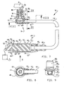
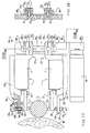
- An inductive transducer 90 of the "half-bridge" type with multiple windings, shown in view in figure 2, and in an enlarged scale in the cross-section views of figures 7 , 8 and 9 , comprises a pair of windings 92 , each divided into two sections, and a core 91 made of ferromagnetic material.
- the core 91 is secured to a stem 93 that is coupled to arm 20 in an adjustable way. More specifically, stem 93 is screwed into a threaded hole 28 located at the end portion 21 of arm 20.
- Each section of the windings 92 is housed in one of the four annular seats of a spool 95 made from a material that has a particularly low sensitivity to thermal variations (for example "liquid crystals” or LCP-Liquid Crystal Polymer).
- the coupling of the windings 92 to the spool 95 does not foresee the use of glue, thereby facilitating the assembly operations and avoiding any possible negative effects due to thermal expansions that glue is subject to.
- the spool 95 is coupled to a hollow support 100 , more specifically is arranged at the interior of a first steel housing, or liner, 101 , between internal limit-stop surfaces at the ends of the liner 101 .
- the position of spool 95 is locked by a free end rim 102 of liner 101 suitably bent by mechanical machining against a substantially truncated-cone end surface, of spool 95 .
- This type of coupling is particularly simple, reliable and easily automated.
- the reliability is improved especially with respect to the known devices in which, owing to the fact they require additional materials - as bonding agents - for their coupling, and as these materials are subject to undesired changes in volume, the thermal variations that the device undergoes can cause displacements among the components of the transducer.
- a second housing 105 - made, for example, of brass - of the hollow support 100 for spool 95 has two parts arranged in substantially perpendicular directions.
- One part 106 is coupled to the liner 101 by means of bent portions, the other part 107 has a C-shaped cross-section (shown in figure 9) and locks the end of a cable 110 for electric wires not shown in the figures.
- a support plate 111 is locked between the first and the second housing ( 101 and 105 ), respectively, of the hollow support 100 and carries an integrated circuit to which there are connected, on the one side the windings 92 and on the other the electric wires of cable 110.
- a protection 117 protects the end portion of cable 110 , the second metal plate housing 105 and an end portion of liner 101 .
- the liner 101 is housed in a through seat 11 on the lower face 7 of casing 3 , and has - at the exterior - a flange 103 with a surface that, by cooperating with a corresponding surface at the entrance of seat 11 , defines the position and enables the coupling of the hollow support 100 by means of two screws 104 that lock diametrically opposite areas of the flange 103 (as shown in figure 5).
- the external surface of liner 101 has a seat for a toroidal-shaped gasket, or "O-ring", 118 that, by remaining pressed between liner 101 and the internal surface of seat 11 , guarantees the coupling sealing.
- the liner 101 can have a different shape with respect to the one illustrated, for example, flange 103 may not be included.
- the fixing and the adjusting of its position in seat 11 can be carried out, for example, by means of a friction screw that - by traversing a hole at the rear face 8 of casing 3 (not shown in the figures) - touches the surface of the liner 101 and locks it in the desired position.
- the arrangement of the components of the inductive transducer 90 is such that the core 91 is housed at the interior of the windings 92 , and can perform (together with stem 93 ) limited, substantially translational, displacements when arm 20 displaces.
- the protection 117 can be achieved by an over-moulding process.
- This process is per se known and substantially consists in a moulding of plastic material, for example polyurethane, to embrace the parts intended to be coated (i.e. in the illustrated arrangement the end part of liner 101, the steel plate housing 105 and an end of cable 110 ).
- This process achieves, in substance, a single, non-dismountable piece.
- the sheath of cable 110 is also made of polyurethane, the over-moulding process provides a fusion with protection 117 that guarantees the sealing of the coupling.
- An additional thrust device comprises two permanent magnets 121 (only one is shown in figure 2), fixed in recess 12 of casing 3 at the lower face 7 , with opposite polarity, placed side by side in a direction that is substantially parallel to the axis of rotation defined by fulcrum 30 .
- the magnets 121 face, with opposite polarities, areas of the arm 20 , for example near the return spring 60 , and apply to arm 20 (made of ferromagnetic material) a magnetic tractive force that adds to the action of spring 60 for urging feeler 27 towards piece 2 to be checked.
- the two magnets 121 are arranged with opposite polarities, the magnetic flux that they generate loops them - through the corresponding areas of arm 20 - and the areas of casing 3 to which they are coupled, and does not apply any action to the other component parts of head 1 .
- the recess 12 can be filled with a viscous liquid, in particular oil (for example, silicon oil, characterized by a high and substantially constant viscosity) intended for cooperating with the transversal surfaces of fin 55 , in the course of the displacements of arm 20 , for damping these displacements.
- oil for example, silicon oil, characterized by a high and substantially constant viscosity
- the damping effect can be easily modified by replacing fin 55 with another fin that has a different shape, in particular transversal surfaces that have a different extension.
- the support and protection structure comprises a cover 130 that is secured, by means of screws not shown in the figures, to the upper face 6 of casing 3 for sealing the opening 15 that provides access to recess 12 .
- the cover 130 has two holes with associated caps 131 and 132 for the insertion of the damping oil in recess 12 .
- One of the holes and its associated cap 132 are arranged at the stem 93 carrying the core 91 of transducer 90 thereby permitting to operate from the exterior of the casing 3 for setting the position of core 91 at the interior of the windings 92.
- a toroidal-shaped gasket 133 (or "O-ring”) is clamped between the cover 130 and the casing 3 and achieves the coupling sealing between cover 130 and casing 3 .
- Two flexible, tubular-shaped, sealing gaskets 134 and 135 are fixed in a known way in annular seats of arm 20 and casing 3 at the central opening 16 .
- the gaskets 134 and 135 are made from a particular type of rubber that is abrasion-proof and high temperature-resistant (for example, HNBR, or hydrogenated nitrile) for protecting the interior of head 1 from swarf, that could cause damage.
- HNBR high temperature-resistant
- HNBR hydrogenated nitrile
- a cover 136 is coupled to the front face 5 of the casing, for example, by means of screws, not shown in the figures.
- transponder 140 An electronic programmable identifier, or "transponder”, 140 is housed in a seat in the lower face 7 of casing 3 .
- the transponder 140 comprises a radiofrequency identification system of a known type that enables, with the aid of appropriate instruments (for example a magnetic read/write unit connected with a processing unit), to insert and detect data identifying head 1 (for example a code number), and/or other data of other nature (for example adjustments made in head 1 , or information relating to operations for the technical assistance).
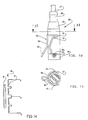
- the electric wires of cable 110 that - as previously described - are connected to windings 92, have opposite ends coupled to a first element 147 of a connector 146, shown in figures 7, 10 and 11.
- a second element 148 of connector 146 is connected, in a known way and not shown in the figures, with a processing unit 81 , and coupled to the first element 147 for featuring the electric connection between the inductive transducer 90 and the processing unit 81.
- the first and the second element 147 and 148 of connector 146 have housings 149 and 150 and central cylinder-shaped elements 151 and 152 , respectively, that carry conductor terminals of a known type (for example plugs and sockets, not shown in the drawings for the sake of simplicity and clarity) cooperating with one another for achieving the electric connection.
- a portion of element 152 with smaller diameter and an internal surface of housing 149 define a hollow cylindrical seat 153 that houses a corresponding end portion with a smaller cross-section 154 of housing 150.
- annular gaskets, or "O-rings”, 155 and 156 are partially housed in annular seats at the end portion 154 of housing 150 and pressed against the internal surfaces of seat 153 for achieving the coupling sealing between the elements ( 147 and 148 ) of connector 146 .
- the housings 149 and 150 for the components of connector 146 have substantially cylindrical external surfaces and a first and a second pair of pins 157 and 158 , respectively, each protruding from its associated external surface and aligned in a diametral direction.
- a rapid locking/unlocking device between the elements 147 and 148 of connector 146 comprises a shaped elastic locking element 159 (shown in figures 10 and 11 only), made, for example, from bent steel wire for springs, with a substantially symmetric shape with respect to a longitudinal plane, with two end slots 160 coupled to pins 158 , two bent hooking portions 161 for cooperating in an elastic way with gripping surfaces of pins 157 , and a central connecting portion 162 located between the locking portions.
- the connecting portion 162 is suitably bent for defining an actuation lever 163 that on the one side contacts the surface of the first element 147 and on the other side has a bent connecting end arranged apart from that surface.
- the elastic thrust applied by the shaped, element 159 to the pairs of pins 157 and 158 keeps the elements 147 and 148 of connector 146 clamped against each other, hence ensures the stability of the electric connection.
- the locking arrangement shown in figures 10 and 11 is achieved in a particularly simple and rapid way, by manually urging the shaped element 159 that, by rotating about an axis substantially defined by the pair of pins 158 , elastically deforms until the hooking between the bent hooking portions 161 and the pins 157 occurs.
- the unlocking is achieved in an equally simple and rapid way, without there being the need to use any tool, by operating on the end of the actuation lever 163 for elastically deforming the shaped element 159 and disengaging the bent, hooking portions 161 from pins 157 .
- a protection 164 achieved by over-molding, coats a part of the first element 147 and the end of cable 110 connected thereto, and is partially inserted in housing 149.
- An annular sealing gasket, or "O-ring”, 165 is arranged between the protection 164 and the internal surface of housing 149 .
- the structure of connector 146 with the shaped locking element 159 and the arrangement of the annular gaskets 155 and 156 enable rapid and safe locking/unlocking operations and ensure the sealing between the elements 147 and 148 .
- the latter feature is particularly important in consideration of the presence of coolants in the applications of head 1 in a machine tool for performing checkings in the course of the machining of pieces.
- the coupling of the shaped element 159 can be modified with respect to what has been herein illustrated and described, for example the slots 160 can be coupled to pins 157 fixed to the first element 148 of connector 146 and the bent hooking portions 161 can be adapted for cooperating with the pins 158 .
- the shape of the pairs of pins 157 and 158 can vary with respect to what has been herein illustrated (with reference to figures 7 and 10).
- the assembly comprising the cable 110 and, joined at the ends of cable 110 by means of protections 117 and 164, the hollow support 100 with the windings 92 on the one side and the first element 147 of the connector 146 on the other side, in substance forms an integral element 166 for the electric connection (figure 7) easily insertable in (and removable from) an apparatus that comprises the head 1 and the processing unit 81.
- the operations required for the insertion and the coupling - in the correct position - of the hollow support 100 to casing 3, as previously described, are particularly simple and rapid. Even the coupling and the locking of the two elements 147 and 148 of connector 146 by means of the elements shown in figures 10 and 11 is easy and rapid, besides being safe and providing tightness.
- the possibility of a rapid insertion of the integral element 166 , shown in figure 7, is an aspect that contributes to making the apparatus particularly flexible and allows, for example, to assemble in an interchangeable way elements that comprise windings 92 (and associated spools 95 and hollow supports 100) of different length for varying the measuring range of head 1.
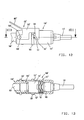
- Figures 12 and 13 schematically show a connector 146' with a rapid locking/unlocking device including some slightly different constructional features with respect to the one of figures 7, 10 and 11.
- a locking element 159' is made, for example, from cut and bent sheet (e.g. sheet-steel) and has end slots 160' pivotably coupled to pins 158' , hooking portions 161' and a central connecting portion 162' defining an actuation lever 163'.
- a first element 147' of the connector 146' substantially differs from element 147 shown in figure 7 in that central cylinder-shaped element 151' (that is shown in view in figure 13) is coupled within housing 149' and elastic elements 167 (e.g.
- a couple of shaped laminar springs that are also shown in view in figure 13) are arranged between element 151' and the bottom end of housing 149' where cable 110 is connected.
- the elastic elements 167 have openings, not shown in the drawings, allowing to properly couple the electrical wires of cable 110 to element 151' .
- the housing 149' of element 147' has a substantially cylindrical external surface and an annular projection 168 with two opposed sloping recesses 169 and notches 157' , the latter defining gripping surfaces adapted to cooperate with hooking portions 161' of locking element 159' .
- a second element 148' of connector 146' is substantially similar to element 148 of figures 7 and 10, and includes the above cited pins 158' .
- Locking and unlocking operations of the connectors 146 and 146' are substantially the same, and are equally rapid and safe.
- the elements 147' and 148' of the connector 146' are locked by urging them against each other and rotating the shaped element 159' about the axis defined by pins 158' until the hooking portions 161' , after having engaged the sloping recesses 169 , lock in the notches 157' .
- the elastic elements 167 are prestressed and - during and after the engagement between hooking portions 161' and notches 157' - apply an elastic pulling force between elements 151' and 152' that keeps the elements 147' and 148' clamped agaist each other.
- the locking/unlocking device features an elastic clamping action that is applied, in connector 146 by the shaped element 159 of figure 10, and in connector 146' by the elastic elements 167 of figure 13.
- the elastic elements 167 of figure 13.
- two springs 167 are shown in figure 13, one or a different number of elastic elements can apply the same kind of elastic action.
- element 147' can be part of an integral element corresponding to element 166 of figure 7.
- the cable 110 can be joined to element 147' by means of a protection obtained through an over-moulding process, or by a different known permanent connection.
- head 1 for example for the checking of a piece 2 in the course of the machining in a numeric control machine tool, is as follows.
- arm 20 Before displacing the head 1 and the piece 2 to be checked towards each other in a known way, in order to prevent the feeler 27 from colliding against surfaces of piece 2, or other obstacles in the course of the approach, arm 20 is displaced to an inoperative position in which the feeler 27 is far from the operating position.
- the retraction device is activated by making air flow, from source 79, inside bellows 70 , by passing through conduits 80 and the hole in cover 71 .
- the pressure applied by the air causes the extension of bellows 70 until contact occurs between the annular limit-stop element 74 and the cylindrical projecting part 76 fixed to arm 20, at seat 75.
- the further extension of bellows 70 urges arm 20 to rotate thereby opposing the action of spring 60 and that of the magnets 121 until the head of screw 50 abuts against the upper surface of wing 22, thus defining the inoperative position of movable arm 20.
- the retraction device is de-energized, progressively reducing air pressure at the source 79 , and the bellows 70 returns to a retracted condition (shown in figure 2) that does not interfere with the measurement displacements of arm 20 , hence urging the air in the bellows to flow out through conduits 80 .
- the elastic recovery of the bellows 70 upon the stopping of the flow of compressed air is guaranteed by the shape and the material from which the bellows is made.
- core 91 - supported by stem 93 - takes a corresponding specific position with respect to the windings 92 of the transducer 90 .
- the electric signals provided by the transducer 90 are indicative of the mutual position of core 91 with respect to windings 92 and, consequently, of the position taken by feeler 27 with respect to a zero position previously set when performing the operations required for the zero setting against a master piece. These signals are sent by transducer 90 , through the wires of cable 110 , to the processing unit 81 that compares the measurement values with previously memorized nominal values of piece 2 .
- the processing unit 81 can be connected, for example, to the numerical control of the machine tool for the machine feedback, in other terms for checking the machining on the basis of the dimensions of piece 2 measured by head 1.
- transducer 90 is of the "HBT", “Half-Bridge Transducer” type, that is insensitive to variations in the length of cable 110 . More specifically, transducer 90 is a half-bridge transducer based on multiple windings, also known as a "HBT multiwinding" transducer, according to a technique that foresees the appropriate splitting of the windings in two or more sections, the utilization of a core 91 of a suitable length, and the obtaining of a transducer linearity range that is particularly broad with respect to the overall dimensions of the transducer.
- Figure 14 schematically shows a possible arrangement of the pair of windings 92 , connected in series, each divided into two sections, and that of the core 91 of transducer 90 .
- the windings 92 are fed by applying to each of the end terminals, A and C , an alternating voltage with respect to ground, the two voltages being identical to each other and in push-pull.
- the voltage with respect to ground at the intermediate terminal B has a consequently theoretically null amplitude at a central position of the core and a variable amplitude as the position of core 91 varies. Amplitude variations are detected, by means of the wires of cable 110 , by the processing unit 81 .
- the windings 92 feed the windings 92 with a single alternating voltage between the terminals A and C.
- the voltage with respect to ground at terminal B at the central position of core 91 has a known amplitude value other than zero (for example identical to half of that of the power supply voltage).
- movable arm 20 In the course of the machining of piece 2 , movable arm 20 , urged by spring 60 , arranges itself in different angular positions (with reference to figure 2 it performs, for example, a limited rotational displacement in a clockwise direction). Consequently, the tension of the spring 60 varies as well as the force that this spring applies to arm 20 ("measuring force"), in particular with broad measuring range heads.
- the different amount of measuring force in the various checking phases can negatively affect the correct operation of head 1 owing to the different strains and deformations that this force causes on the surface of piece 2 to be checked and on the component parts of the head.
- feeler 27 alternatively touches surface portions angularly separated from each other by falling, between a portion and the following one - owing to the absence of contact with the surface - of an amount that directly depends on the tractive force that arm 20 undergoes. When contact is made again with the subsequent cylindrical surface portion, feeler 27 collides against a surface that laterally limits this cylindrical portion.
- the total amount of force (“measuring force”) applied to arm 20 is substantially kept constant thanks to the action of the magnets 121 at the corresponding areas facing arm 20.
- the forces applied by spring 60 and by magnets 121 vary in opposite direction as the angular position of arm 20 varies. More specifically, with reference to the arrangement shown in figure 2, the limited rotational displacements in a clockwise direction that arm 20 undergoes in the course of the machining of piece 2 cause an approach between the portion of arm 20 to which there is coupled an end of spring 60 and the internal surfaces of recess 12 of casing 3 to which the other end of spring 60 is coupled to and where the magnets 121 are arranged.
- the head 1' is substantially identical to the one shown in figures 1-6, apart from the retraction device.
- bellows 70 (shown in figure 2) is not arranged in seat 10, and an adjustment device 170 , that defines an associated longitudinal adjustment axis, is coupled to the rear face 8 of casing 3 at a position corresponding to a through hole 17 .
- the adjustment device 170 comprises a hollow cylinder 171 , externally arranged with respect to the casing and an adjustable locating piston 172 (shown in figure 15 only partially cross-sectioned), housed in cylinder 171 , that can perform translation displacements along the longitudinal axis of device 170 .
- the piston 172 has a sloping abutment surface 173 , at an end arranged inside casing 3 , that cooperates with an end 29 of the end portion 21 of arm 20 (shown in view in figure 15).
- An actuation element comprises a screw 174 that traverses a through hole 175 of cylinder 171 and is coupled, by means of an adjustable threaded coupling, to the other end of the locating piston 172 .
- a hollow cylindrical cover 176 with a centrally located access hole 177 is externally coupled to cylinder 171 and restrains the head of screw 174 thereby allowing it to perform only rotational displacements about its axis, with respect to cylinder 171 .
- a guide device for preventing substantial axial rotations between the piston 172 and the cylinder 171 comprises a trasversal pin 178 fixed to the internal surface of the hollow cylinder 171 and partially housed in a slot 179 defined on the external surface of the locating piston 172 .
- the position of the sloping surface 173 can be set in such a way so as to define, thanks to the contact with the end 29 of arm 20 urged by the thrust of spring 60 , the position of feeler 27 (not shown in figure 15 for the sake of simplicity) when the head 1' is in rest conditions, i.e. when no contact occurs between feeler 27 and piece 2 .
- the action provided by the sloping surface 173 substitutes that of the limit-stop dowel 51 (shown in figure 15).
- the adjustment device 170 just for adjusting the position of feeler 27 under rest conditions, as previously described, in a head that comprises a retraction device with bellows 70 , like the one illustrated in figure 2.
- the adjustment device 170 can also be coupled to the rear face 8 of casing 3 in a position substantially rotated by 180 degrees about its longitudinal axis with respect to the one shown in figure 15.
- the position of the sloping surface 173 is set for limiting, by contact occurring with the end 29 of the end portion 21 , the rotations of arm 20 in a counter-clockwise direction (with reference to figure 15) and defining the inoperative position of arm 20 to which the arm 20 is brought by a retraction device comprising, for example, the bellows 70 shown in figure 2.
- the head 1" shown in figure 16 is similar to the one shown in figure 15, and comprises an adjustment device 170' with an electric motor 180 coupled to a piston 172 for adjusting its position.
- the components of the device 170' are substantially identical to those of the adjustment device 170 shown in figure 15, with the exception of the electric motor 180 that comprises a rotatable spindle 181 , that has an end coupled - through the access hole 177 - to the head of screw 174 .
- the electric motor 180 is connected to the processing unit 81 from which it receives actuation signals for displacing arm 20 to the inoperative position, and/or for adjusting the position of the feeler 27 (not shown in figure 16 for the sake of simplicity) when the latter is under rest conditions, by displacing the sloping surface 173 as described with reference to figure 15.
- the possibility of automatically adjusting the position of feeler 27 under rest conditions, on the basis of the measuring signals that the processing unit 81 receives from head 1" is particularly advantageous when the head 1" performs the checkings of pieces with grooved surfaces.
- the feeler 27 alternatively touches - even at very high frequencies - surface portions angularly separated from each other and falls - between one portion and the following one - of a certain entity (when there is no contact with the surface) and undergoes considerable impacts, along directions substantially tangential to the surface of the piece, when contact is resumed.
- the distance between the positions where the feeler 27 is in its rest position and in contact with the surface portions be relatively small.
- the head 1" shown in figure 16 enables the dynamic setting of the position of feeler 27 in a rest condition (i.e.
- adjustment device 170' and other combinations with other retraction devices (for example, the bellows 70 ) and/or limiting device (screw 50, dowel 51 ) are possible in an entirely identical way to what has been hereinbefore described with reference to device 170 , shown in figure 15.
- other retraction devices for example, the bellows 70
- limiting device screw 50, dowel 51
- measuring heads 1, 1' and 1 measuring heads that comprise the described characteristics also fall within the scope of the invention.
- gauging or measuring heads that incorporate just some of the herein described and illustrated characteristics, relating, for example, to the structure of the transducer 90 and/or the connector 146/146' are also within the scope of the invention.
- fulcrum utilized in the heads 1, 1' and 1" according to the invention that consists in the deformable element 30 , has a particularly simple, compact and inexpensive structure. Besides guaranteeing extremely accurate displacements of arm 20 , fulcrum 30 enables extremely simple and rapid operations for the coupling to the reciprocally movable parts (arm 20 and casing 3 ).
- the manufacturing aspects of the deformable element 30 can differ with respect to what has been described and illustrated in the figures.
- the number of laminae can be reduced to two (for example, laminae 31 and 32 , shown in figure 6).
- one of the two laminae can have a different shape: in particular, there can be foreseen an embodiment wherein the two coplanar laminae 31 and 33 are replaced by a single lamina with a central opening for the passage of lamina 32 .
- Even the arrangement of the laminae can differ, since the reciprocal angular position and the arrangement with respect to blocks 34 and 35 can vary.
- there can be foreseen for example, a fulcrum comprising two reciprocally parallel laminae permanently coupled to blocks 34 and 35 .
- An advantageous feature that the above illustrated and described heads provide consists in the specific compactness, by virtue of the absence of intermediate supports and the coupling of the components (fulcrum, return spring, elements of the transducer and limiting devices) directly to casing 3 .
- the possibility of reducing to a minimum the layout dimensions of the heads is particularly advantageous when the space available is limited, for example in the case of "in-process" applications, i.e. when the mechanical pieces are checked in the course of the machining in a machine tool.
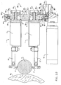
- the apparatus shown in figures 17 and 18 comprises a first support and reference system 200 for two heads 1, substantially gauging heads similar to those hereinbefore described and illustrated, for example, with reference to figures 1-5.
- the heads 1 are shown in view in figure 17, that substantially illustrates the casings 3, the feelers 27 and the associated supports identified by reference number 26'.
- the system 200 comprises a stationary structure 205 including a base 206 coupled, as shown in figure 17, to a pneumatic slide of a known type identified by reference number 199 , and a stanchion 207 rigidly coupled and perpendicular to base 206 .
- a side of the stanchion 207 (the front side in figure 17) has an elongate seat 208 that houses two prismatic blocks 209 each carrying a cylindrical pin 210 perpendicularly arranged with respect to said side of stanchion 207 .
- blocks 209 enable the latter to slide with a limited amount of clearance in seat 208 and the blocks 209 can be coupled in pre-set positions by means of screws 211 that traverse stanchion 207 by passing through holes 212 defined at the elongate seat 208 . There can be foreseen a plurality of pairs of holes 212 for the coupling of the blocks 209 in a number of positions on stanchion 207 .
- Adjustable, coupling supports 215 are rigidly coupled, for example by means of screws not shown in the figures, to the rear face 8 of heads 1 and each has a first portion 216 for the adjustable coupling to one of the cylindrical pins 210 and a second elongate portion, or reference arm, 225 , substantially arranged in a direction parallel to the longitudinal geometric axis of the associated head 1 .
- each support 215 defines a hole 218 for housing the associated pin 210 with a specific amount of negative allowance, and a slit 219 that enables to elastically vary the amplitude of hole 218 and clamp, with an amount of force that is adjustable by operating a screw 220 , the first portion 216 on pin 210 , hence achieving the coupling between the support 215 and the stanchion 207 of the stationary structure 205 .
- the clamping force defined by screw 220 provides a frictional coupling that enables to keep the associated head 1 in a pre-set angular position in the course of the checking operations, and vary this angular position, about an axis defined by pin 210 , in the course of the zero setting operations, or in consequence of impacts that heads 1 undergo, as hereinafter described.
- the reference arms 225 comprise shaped, free ends 226 , substantially arranged parallel to arms 20 of the associated heads 1 , with holes 227 that house adjustable reference mechanisms 228 , and locking screws 229 for locking the position of the mechanisms 228 in the associated holes 227 .
- the two reference mechanisms 228 are identical to each other and only one (shown cross-sectioned in figure 17) is hereinafter briefly described.
- the mechanism 228 comprises a tubular guide and reference element 230 , inserted in the associated hole 227 and held in position by means of the locking screw 229 , that houses and guides a movable element, more specifically a nail 231 with a head 232 and a substantially ball-shaped end 233 that defines an abutment portion facing arm 20 of head 1 .
- Elastic thrust means comprise a compression spring 234 arranged between the tubular element 230 and the head 232 of nail 231, while annular abutment surfaces 235 and 236 are defined by nail 231 for cooperating with surfaces of the tubular element 230 and define a rest and a reference position, respectively, of nail 231 .
- a tubular sealing gasket 237 is coupled between the head 232 of nail 231 and the tubular element 230 in a known way that is not shown in figure 17, for the sake of simplicity and clarity.
- the apparatus shown in figure 17 can be utilized for the external diameter checking of a cylindrical piece 2' in the course of the machining in a grinding machine by a grinding wheel M. Before the checking operations begin, the apparatus shown in figure 17 is zero-set against a master piece in the following way. For each head 1 , the position of the tubular element 230 in hole 227 is set in a suitable way by operating the locking screw 229 . The choice of this position is an aspect that will become more apparent in the course of the following description.
- the master piece is placed in the checking position and the angular arrangement of the heads 1 about the axes defined by pins 210 is such that the feelers 27 are at a specific distance from the surface of the master piece.
- the nails 231 are displaced to the reference positions defined by contact occurring between the surfaces 236 and the tubular element 230.
- the position of the associated arm 20 with respect to the master piece is set, and the rotation of the support 215 and the head 1 continues for a very short stroke until reaching contact between the end 233 of nail 231 and a stop surface of the movable arm-set of the head, in particular of the support 26' for the feeler 27 .
- the arrangement of arm 20 with respect to casing 3 set in this way for each head 1 , corresponds (thanks to the coupling of the tubular element 230 in the suitably chosen hole 227 , as previously described) to a zero setting configuration of head 1 , i.e. a configuration according to which the reciprocal position between core 91 and windings 92 of the transducer 90 is set in a known zero position.
- the frictional coupling with the cylindrical pins 210 allows rotational displacements of heads 1 in the event there be applied a force of a certain entity to the associated coupling supports 215 , for example, as a consequence of accidental impacts that the heads, the supports 26' for the feelers 27 and/or the coupling supports 215 could undergo, hence preventing any possible breakage of or damage to the various internal and external components of heads 1 .
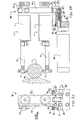
- the apparatus shown in figures 19 and 20 comprises a second support and reference system 500 for two heads 1, substantially similar to those shown in figure 17.
- the heads 1 are shown in a view where the casings 3 , feelers and associated supports, identified by reference number 27' and 26" , respectively, are substantially shown.
- the system 500 comprises a stationary structure 505 including a base 506 coupled, as shown in figure 19, to a pneumatic slide of a known type identified - as in figure 17 - by reference number 199 , and a stanchion 507 perpendicular to base 506 and coupled thereto.
- a connecting block 501 is fixed to the stanchion 507 by means of screws 520 and has a transversal through hole 508 housing a bolt 511 .
- Adjustable coupling supports 515 are rigidly coupled, for example by means of screws not shown in the figures, to the rear face 8 of heads 1 and each has a connecting portion 516 with a through hole 518 for the adjustable coupling to the connecting block 501 .
- connecting portions 516 are arranged on both sides of the connecting block 501 in such a way that holes 518 and 508 are lined up to house bolt 511 .
- a frictioning layer shown in figure 20 by means of a thick, black line 519 , is arranged between the mutually facing surfaces of each portion 516 and block 501 .
- Each layer 519 can be achieved by means of a simple surface treatment of one of the parts, for example connecting portion 516 , including hot spraying on the surface a hardening substance such as a "WIDIA" compound.
- a washer 513 is engaged to the bolt 511 at a free end thereof, the latter being interlocked to a nut 510 that is connected to a wrench 512 to fasten and loosen the coupling between the supports 515 and the connecting block 501 .
- the two connecting portions 516 are urged against the connecting block 501 by the head of bolt 511 on one side and by the washer 513 on the other side.
- a screw having a large flat head 514 is threadedly coupled to the free end of the bolt 511 to keep the wrench 512 engaged to the nut 510 .
- An adjustable reference mechanism 528 is coupled to each head 1 and includes a first reference device and a second adjusting device.
- the two reference mechanisms 528 are identical to each other and only one (shown more in detail in figure 20) is hereinafter briefly described.
- the first reference device includes a frame 523 fixed to the front face 5 of casing 3 by means of screws 524 and a substantially L-shaped striker 531 coupled to the frame 523 and rotatable about a pivoting axis substantially parallel to the longitudinal geometric axis of associated head 1.
- a torsion spring 534 is arranged between an arm of the striker element 531 and one of the screws 524 to urge the former in a retracted rest position against the abutment surface of a limit pin 535 fixed to the frame 523 .
- the striker element 531 can be manually rotated around the pivoting axis from the above mentioned rest position to contact the abutment surface of one of the screws 524 in correspondence of a reference position.
- the second adjusting device is coupled to the end portion 25 of arm 20 and substantially include a transversally adjustable threaded pin 530 , just a free end of which is shown in figures 19 and 20, defining a stop surface.
- Element 531 defines a reference end surface 533 adapted to touch the threaded pin 530 during the zero-setting operations of the apparatus.
- the apparatus shown in figure 19 can be utilized, for example, for the external diameter in-process checking of a cylindrical piece 2' , as explained for the apparatus of figure 17, and corresponding zero-setting operations against a master piece are carried out.
- the transversal position of the threaded pin 530 is manually adjusted in a suitable way, according to a choice that will become more apparent in the course of the following description.
- the master piece is placed in the checking position and the angular arrangement of the heads 1 about the axis defined by hole 508 of the connecting block 501 is such that the feelers 27 are at a specific distance from the surface of the master piece.
- a force is manually applied to the L-shaped elements 531 of both heads 1 , and the elements 531 are first displaced to the reference positions.
- the position of the associated arm 20 with respect to the master piece is set, and the rotation of the associated support 515 and head 1 continues for a very short stroke until reaching contact between the reference end surface 533 of element 531 and the threaded pin 530 coupled to arm 20 .
- the arrangement of arm 20 with respect to casing 3 set in this way for each head 1 , corresponds (thanks to the coupling of the properly adjusted arrangement of the pin 530 , as previously cited) to a zero setting configuration of head 1 , i.e. a configuration according to which the reciprocal position between core 91 and windings 92 of the transducer 90 is set in a known zero position.
- the frictional coupling between the supports 515 and the connecting block 501 - obtained by means of the layers 519 - allows rotational displacements of heads 1 with respect to the stationary structure 505 in the event there be applied a force of a certain entity to the associated coupling supports 515, for example, as a consequence of accidental impacts that the heads 1, the supports 26' for the feelers 27 and/or the coupling supports 515 could undergo, hence preventing any possible breakage of or damage to the various internal and external components of heads 1 .
- the apparatus shown in figures 21 and 22 comprises a third support and reference system 250 for two heads 1, substantially similar to those shown in figures 17 and 19.
- the heads 1 are shown in view and the casings 3 , the feelers 27 and the associated supports, identified by reference number 26" , are also substantially shown.
- the system 250 comprises an elongate coupling support 260 to which there are coupled the heads 1 and a stationary structure, or frame, 270 to which the elongate support 260 is coupled in a removable way.
- Locking elements 251 are rigidly coupled, for example by means of screws not shown in the figures, to the rear face 8 of each head 1 and each has a threaded tang 252, substantially aligned along the longitudinal geometric axis of the associated head 1.
- the elongate support 260 defines a main layout direction and has two slots 261 , aligned in this main layout direction, traversed by the threaded tangs 252 .
- the elongate support 260 comprises a first reference pin 262 , arranged near a first end of support 260 (lower end) along a transversal direction, more specifically, perpendicular to the main layout direction.
- first reference pin 262 At the opposite end of support 260 (i.e. the upper end) there are coupled two additional cylindrical, reference pins 263 and 264 , respectively, with plane upper portions, aligned in a direction parallel to that of the first pin 262 , and a cylindrical insert 265 in an intermediate position between the two second reference pins 263 and 264 .
- frame 270 comprises a base 271 coupled to a pneumatic slide of a known type, identified - as in figures 17 and 19 - by reference number 199 , a stanchion 272 , rigidly coupled to base 271 and perpendicular to it, and a cross-piece 273 , coupled to the free end of stanchion 272 that is substantially parallel to base 271 .
- the cross-piece 273 comprises a bottom seat 276 , substantially V-shaped, and a central prismatic opening 277 with an access slot 278 on a lateral wall of cross-piece 273 (the wall lying in the plane of figure 21).
- a thrust device comprises a thrust lever 280 , of a substantially prismatic shape, with an end coupled to base 271 by means of a lamina 281 and a relief rim 282 at the opposite, free end. Near rim 282 , at a side of lever 280 , there is a pair of balls that defines a reference seat 283 and at the opposite side there is an annular relief 284 .
- the base 271 has a cylindrical seat 286 , that houses a central reference pin 287 , and a threaded hole 288 for the coupling of a limit screw 289 , that traverses a through hole 285 of the thrust lever 280 , and comprises an expanded head arranged in a suitable seat of lever 280 .
- the annular relief 284 houses in the cylindrical seat 286 and is guided by the central reference pin 287 , while contact between the surfaces of lever 280 and the head of screw 289 on the one side and the end of the pin 287 on the other side limit in a clockwise and in a counter-clockwise direction (with reference to figure 22), respectively, the rotational displacements of lever 280 about a transversal axis defined by lamina 281 .
- the thrust device comprises elastic elements with compression springs 290 , for example of the so-called "cup” type, housed in the cylindrical seat 286 for urging the lever 280 to rotate in a counter-clockwise direction, away from the base 271.
- the heads 1 check the external diameter of a cylindrical piece 2" in the course of the machining in a grinding machine by a grinding wheel M, in an application entirely similar to the one schematically shown in figures 17 and 19.
- the heads 1 are coupled to the elongate support 260 as hereinbefore described, in suitable mutual positions that take into account the initial and the final dimensions of the machined pieces to be checked and the measuring range of the heads 1 .
- the elongate support 260 is in turn coupled - as hereinafter described - to frame 270 , the position of which with respect to piece 2" can be checked in a known and herein not specified way.
- the upper end of support 260 is coupled to cross-piece 273 in such a way that the second reference pins 263 and 264 engage in the bottom seat 276 while the cylindrical insert 265 engages with limited clearance, through access slot 278 , in the central prismatic opening 277 .
- the lower end of elongate support 260 contacts the thrust lever 280 , more specifically, the first reference pin 262 is arranged in the reference seat 283 defined by the pair of balls.
- the position of the heads 1 , coupled to the elongate support 260 is set and referred, in an extremely simple, rapid and accurate way, with respect to frame 270 .
- the specific arrangement and shape of the elements that achieve the coupling (pins 262 , 263 , 264 and insert 265 on the one side, seats 276 and 283 , the opening 277 and the slot 278 on the other side) and the elastic thrust of the lever 280 enable the support 260 to release from the frame 270 in the event a force of a certain entity be applied to support 260, for example as a consequence of undesired impacts that the heads 1 could undergo in any direction, thereby preventing the possible breakage of or the damage to the component parts of the heads 1.
- the support 260 carrying the heads 1 can be re-coupled to frame 270 once the cause determining the release has been removed. It should be realized that, in the event the support 260 be released from frame 270 , for example, owing to an undesired impact, the particular shapes, dimensions and reciprocal arrangements of the two parts (i.e. support 260 with the heads 1 on the one side and frame 270 on the other side) in substance prevent a total detachment and the consequent falling of the heads 1 , and damages to them.
- the assembly including support 260 and heads 1 releases by yielding to undesired impacts and hence avoiding breakages, but it remains, in some manner, inserted between the base 271 , the stanchion 272 and the cross-piece 273 of frame 270 , preventing in this way possible dangerous falls and facilitating its retrieval.
- Some of the manufacturing details that contribute to preventing the assembly including support 260 and heads 1 from falling are the coupling arrangement between the cylindrical insert 265 and the central opening 277 with an access slot 278 and the presence of the relief rim 282. In fact, both these details prevent the support 260 from releasing at the side of the piece to be checked 2" that could cause not only the falling of support 260 (i.e.
- the apparatus illustrated in figures 23 and 24 comprises a fourth support and reference system 300 for two heads 1, substantially similar to those of figures 17, 19 and 22.
- the heads 1 are shown in view and the figure substantially shows the casings 3, the feelers 27 and the associated supports that, as those of figure 22, are identified by reference number 26".
- the fourth support and reference system 300 is under certain aspects similar to the third system 250 shown in figures 21 and 22, and comprises an elongate coupling support 310 to which there are coupled the heads 1 and a stationary structure, or base, 320 to which there is coupled, in a releasable way, the elongate support 310 .
- base 320 is coupled to a pneumatic slide of a known type, identified by reference number 199, as the one of figures 17, 19 and 22.
- the heads 1 are coupled to the elongate support 310 in the adjustable way already described with reference to the coupling between the heads 1 and the elongate support 260 of figure 22.
- the elongate support 310 comprises a thrust device with an elongate, elastic element 315 coupled, by means of screws 314 , at an (upper) end of support 310 in such a way so that the elastic element 315 and the support 310 are substantially parallel along a main layout direction.
- a free end of the elongate elastic element 315 has a reference element with a transversal pin 316 that has a ball-shaped end.
- the elongate support 310 has - at an opposite (lower) end - another reference element with an adjustable threaded pivot 317 that also has a ball-shaped end. Pin 316 and pivot 317 are substantially aligned along a coupling direction.
- a support lever 303 is coupled to the lower end of the elongate coupling support 310 (for example, by means of a screw not shown in the figures) and comprises a short end 304 , that extends below the lower end of support 310 and is substantially parallel to its main layout direction, and a long end 305 arranged substantially perpendicular to both the main layout direction and the transversal coupling direction, that carries at a free end an additional reference element, more specifically, a support pin 306 .
- the base 320 comprises two parallel, vertical wings 321 and 322 that define opposite conical seats 323 and 324 aligned in a transversal coupling direction. Moreover, the base 320 has a cylindrical hole 325 that houses an additional thrust device, that comprises a compression spring 326 and a cylinder-shaped element 327 that can slide in hole 325 and is urged by spring 326 towards the exterior of base 320 .
- Two reference pins 328 and 329 are coupled to base 320 and have substantially conical ends facing the lower end of support 310 .
- the heads 1 check the external diameter of a cylindrical piece 2" in the course of the machining in a grinding machine with a grinding wheel M, in an application that is entirely similar to the one schematically illustrated in figures 17, 19 and 22.
- the heads 1 are coupled to elongate support 310 in suitable reciprocal positions that take into account the initial and the final dimensions of the machined pieces to be checked and the measuring range of the heads 1 .
- the elongate support 310 is in turn coupled - in the manner hereinafter described - to the base 320, the position of which, with respect to piece 2" can be defined in a known and herein not described way.
- the elongate support 310 is coupled to base 320 at the lower end only. More specifically, support 310 is moved towards base 320 and, with the aid of pins 328 and 329 that achieve a rough, reference limit-stop for the lower end of support 310 , the ball-shaped ends of the transversal pin 316 and that of the threaded pivot 317 are inserted in the oppositely arranged conical seats 323 and 324 .
- the position of pivot 317 along the transversal coupling direction is set by operating the threaded coupling between pivot 317 and support 310 , so as to set in a suitable way the thrust applied by the elastic element 315 .
- any rotations of the support 310 , and consequently of the heads 1 , about the transversal axis of coupling are prevented by the cooperation between the support lever 303 and the base 320 .
- the support pin 306 is abutted against a plane reference surface 330 of base 320 thanks to the action of the cylinder-shaped element 327 , that is urged by spring 326 , against the short end 304 of lever 303 .
- the thrust that the spring 326 applies is sufficient for keeping - when the apparatus is under normal working conditions-pin 306 abutted against the surface 330 of base 320, as in the arrangement of figure 24.
- the position of the heads 1 , coupled to the elongate support 310 is fixed and determined in an extremely simple, rapid and accurate way with respect to base 320 .
- the specific arrangement and shape of the elements that achieve the coupling (the ball-shaped ends of pin 316 and pivot 317 in the conical seats 323 and 324 , the abutment of pin 306 on a plane surface) and the elastic thrust of the elongate element 315 and of the device that comprises the spring 326 and the element 327 enable support 310 to release from the base 320 in the event a force of a certain entity be applied to support 310, for example, as a consequence of undesired impacts that the heads 1 undergo substantially in any direction.
- the support 310 carrying the heads 1 can be re-coupled to base 320 once the cause for the release has been removed.
- the elongate elastic element 315 can be coupled to support 310 so as to undertake a different arrangement, not necessarily parallel to the support 310 , that also guarantees the aligning between pin 316 and pivot 317 along a coupling direction.
- FIGS. 23 and 24 show a support and reference system 300' that is substantially similar - insofar as the structure and the operation are concerned - to the system 300 shown in figures 23 and 24. Only the main manufacturing differences are herein briefly described.
- Two conical seats 323' and 324' are achieved in wings 321' and 322' of base 320' , aligned in a transversal direction.
- a thrust device with an elongate elastic element 315' is coupled, by means of screws, to the elongate coupling support 310' and has, at a free end, a reference element 316' with spherical surface.
- Another reference element 317' is coupled to the elongate element 310' , facing element 316' and aligned with it in a coupling direction.
- Limiting and protection surfaces fixed to the stationary structure for limiting the displacements of the support lever 303' and those of the elongate element 310' fixed to it are schematically shown and identified by reference number 340 in figure 26.
- the apparatus illustrated in figures from 27 to 30 comprises a fifth support and reference system 350 for two heads 1 , substantially similar to those shown in figures 17, 19, 22, 24 and 26.
- the heads 1 are shown in view and there are substantially shown the casings 3, the feelers 27 and the associated supports that, as those of figures 22 and 24, are identified by reference number 26".
- the fifth support and reference system 350 is under certain aspects similar to the fourth system 300 shown in figures 23 and 24, and comprises a coupling support 355 to which there are coupled the heads 1 and a stationary structure, or frame, 370 to which there is coupled, in a releasable way, the coupling support 355.
- the coupling support 355 too is coupled to frame 370 at a lower end area of this support 355, and the latter carries the heads 1 with similar adjustable couplings.
- the coupling support 355 comprises a vertical, elongate portion 360 that carries the heads and a plate 361 arranged in a substantially horizontal plane, with reference elements comprising two balls 362 and 363 fixed to a side base of plate 361 , and a pair of pins 364 and 365 with ball-shaped ends, coupled to plate 361 at the opposite side base, and arranged along directions perpendicular to plate 361 .
- a rotary pin 366 houses in a through hole 369 of plate 361 (figure 30) and has a first end facing an opening 367 of the plate 361 , whereas the second end is coupled to an actuation lever 368 .
- the frame 370 is coupled, in the arrangement shown in figure 25, to a pneumatic slide of a known type identified by reference number 199 as in the figures 17, 19, 22, 24 and 26 and comprises a base 371, a wall 372 rigidly coupled to a side of the base and perpendicular to it, and two columns 373 and 374, rigidly coupled at the opposite side of the base 371 and substantially perpendicular to it.
- the wall 372 has a central opening 375 near the base 371, and a transversal pin 376 is coupled to the frame 370 at this opening 375 .
- the column 373 has a substantially angular shape with an end portion 377 arranged in a direction parallel to the base 371 , and carries, fixed to the end portion 377 , a pin 378 that defines an anchorage surface, parallel to the transversal pin 376 .
- a conical seat 380 and a V-shaped seat 381 are defined in the internal surface of wall 372 , near the side of the latter opposite to base 371 , aligned along a transversal direction that is parallel to pin 376 .
- a thrust and locking device comprises an elastic element with a return spring 390 , and a locking element with a hook 391 .
- the ends of the spring 390 are hooked to the transversal pin 376 , fixed to base 371 , and to a through hole 392 in an end portion of hook 391 , respectively.
- the rotary pin 366 coupled to plate 361 , is rigidly fixed to hook 391 , in a central hole 393 of the latter, at the opening 367 of plate 361 , so that the rotations of the pin 366 cause corresponding rotations of hook 391 about a transversal axis defined by pin 366 .
- the hook 391 also comprises an anchorage end portion 395 for cooperating with the anchorage surface of pin 378 for achieving the locking between the coupling support 355 carrying the heads 1 and the frame 370 , as hereinafter described.
- the heads 1 check the external diameter of a cylindrical piece 2" during the machining in a grinding machine with a grinding wheel M, in an application that is entirely similar to the one schematically shown in figures 17, 19, 22, 24 and 26.
- the heads 1 are coupled to the elongate portion 360 of support 355 in appropriate reciprocal positions that take into account the initial and the final dimensions of the machined pieces to be checked and the measuring range of the heads 1 .
- the coupling and the locking between the support 355 and the frame 370 for defining a checking position of the heads 1 occurs in the following way.
- pins 364 and 365 fixed to plate 361 , rest on reciprocally coplanar rest surfaces defined by columns 373 and 374 and the balls 362 and 363 are inserted in the associated conical seat 380 and "V" shaped seat 381 of wall 372 , respectively, hence achieving the coupling shown in figure 29.
- One of the two pins 364 and 365 can be coupled to plate 361 in a way (that is not illustrated in the figures) adjustable along its axis, or can be left out, for achieving a substantially isostatic coupling between the coupling support 355 and the frame 370 .
- lever 368 is manually actuated for rotating the hook 391 (in a counter-clockwise direction with reference to figure 29) until there is achieved the cooperation between the end portion 395 and pin 378 , shown in figures 27, 28 and 30.
- the tension force of the spring 390 increases until there is reached a maximum value that corresponds to the angular position in which the rotary pin 366 is centered on the straight line of action of spring 390 (i.e. the axis of the through hole 392 where an end of the spring 390 is hooked to lies in a plane defined by the axes of pins 366 and 376 ), thereafter decreasing until contact between the anchorage portion 395 and pin 378 occurs; in this position the rotary pin 366 is off-set only by a small amount, below the formerly mentioned straight line of action.
- the configuration shown in figure 28 achieves the locking of plate 361 to frame 370 in the arrangement defined by the reference elements and the associated seats and support surfaces.
- the tractive force of the spring 390 tends to maintain the cooperation between the anchorage portion 395 and pin 378 , besides urging the balls 362 and 363 in the associated seats 380 , 381 and the ball-shaped ends of pins 364 and 365 against the associated support surfaces of columns 373 and 374 .
- the tractive force of spring 390 contributes to the rotation (in a clockwise direction with reference to figure 28) enabling the unlocking of the parts (figure 29).
- This characteristic of the thrust and locking device is particularly advantageous for contributing to the disengagement of support 355 from frame 370 in the event that a force of a certain entity be applied to support 355 , for example, further to the heads 1 undergoing undesired impacts, thereby avoiding the possible breakage of or the damage to parts of the heads 1 .
- the apparatus illustrated in figures 31 and 32 comprises a sixth support and reference system 400 for two heads 1, that under some aspects is similar to the systems 250, 300, 300' and 350 of figures from 21 to 30 and comprises an elongate coupling support 410 to which there are coupled the heads 1 and a stationary structure, or frame, 420 to which there is coupled, in a releasable way, the elongate support 410.
- the heads 1 are coupled to the elongate support 410 in the adjustable way that has been previously described with reference to the coupling between the heads 1 and the elongate support 260 of figure 22.
- the frame 420 comprises a base portion 421, secured, for example, to a pneumatic slide 199, and a bridge-type structure, fixed to it, with two stanchion walls 422 , 424 and a cross-piece 423 .
- One of the two walls 422 features slits that define thrust means with two portions 425 and 426 elastically movable with respect to the rest of the frame 420 .
- the elongate support 410 defines lateral surfaces 411 and 412 intended to be arranged facing the walls 422 and 424 and comprises reference elements with four balls 413, 414, 415 and 416 arranged by pairs on surfaces 411 and 412, aligned two by two ( 413/415 and 414/416 ) along transversal coupling directions near the ends of the elongate support 410.
- the bridge-type structure of frame 420 defines four seats for the reference elements, more particularly two slots 433 and 434 in the elastically movable portions 425 and 426 of wall 411 , and a circular hole 435 and a slot 436 in the wall 412 .
- Two pairs of oblique slots are obtained in the walls 411 and 412 (just the pair of slots 428 in the stationary part of wall 411 is shown in figure 27).
- Two return springs 402 and 403 are arranged along transversal directions between the wall 412 and the elastically movable portions 425 and 426, respectively.
- the heads 1 check the external diameter of a cylindrical piece 2" in the course of the machining in a grinding machine with a grinding wheel M.
- the heads 1 are coupled to the elongate support 410 in suitable reciprocal positions that keep into account the initial and the final dimensions of the machined pieces to be checked and the measuring range of the heads 1.
- the elongate support 410 is in tum coupled - as explained below - to frame 420 , the position of which - with respect to piece 2" - can be defined in a known and herein not described way.
- the support 410 is inserted at the interior of the bridge-type structure of frame 420 and arranged in such a way that the balls 413 , 414 , 415 and 416 house in the associated seats 433 , 434 , 435 and 436 and define a checking position of heads 1 .
- two pairs of limit pins are inserted in the oblique slots 428 and fixed to the surfaces 411 and 412 of support 410 (for example screwed into suitable threaded holes, not shown in the figures).
- the position of the heads 1 , coupled to the elongate support 410 is set and determined in an extremely simple, rapid and accurate way with respect to frame 420 .
- the specific arrangement and the shape,of the elements that achieve the coupling (balls 413-416 and seats 433-436 ) and the elastic thrust applied by the movable portions 425 and 426 and by the springs 402 and 403 enable the support 410 to release from the frame 420 in the event a force of a certain entity be applied to the support 410 , for example as a consequence of undesired impacts that the heads 1 could undergo substantially in any direction; in this way there is prevented the possible breakage of or the damage to parts of the heads 1.
- the presence of the pins 408 in the oblique slots 428 limits the mutual displacements between the frame 420 and the elongate support 410 , enabling the previously mentioned release but preventing the complete detaching of the frame 420 and the fall of the elongate support 410 with the heads 1. This enables on the one side to avoid damage to the heads 1 and on the other to facilitate and speed up the operations for the coupling between support 410 and frame 420 for bringing the heads 1 back to the determined checking position.
- the sixth support and reference system can differ with respect to what is illustrated in figures 31 and 32, for example insofar as the springs 402 and 403 are concerned. More specifically, depending on the dimensions and the shape of the components of the system 400 , these springs 402 and 403 can be left out in the event the thrust applied by the portions 425 and 426 is sufficient for keeping the correct coupling between the balls 413-416 and the associated seats 433-436, in other terms for keeping the heads 1 in the determined checking position in the course of the normal functioning of the apparatus.
- the figures 33 and 34 show a support and reference system 400' with an elongate support 410' , a frame 420' and other features that are substantially similar - insofar as the structure and the operation are concerned - to features of the system 400 shown in figures 31 and 32. Only the main manufacturing differences are herein briefly described.
- the frame 420' comprises a base portion 421' and a bridge-type structure, fixed to it, with two stanchion walls 422' , 424' and a cross-piece 423' .
- One of the two walls 422' features a substantially L-shaped slit that defines thrust means with a portion 425' elastically movable with respect to the rest of the frame 420'.
- the elongate support 410' defines lateral surfaces 411' and 412' intended to be arranged facing the walls 422' and 424' and comprises reference elements with three balls 413', 415' and 416' fixed to surfaces 411' and 412' .
- a couple of balls 415' , 416' is arranged on one ( 412' ) of the surfaces near the ends of the elongate support 410' , whereas the other ball 413' is arranged on the opposed surface 411' in a substantially centered position.
- stanchion wall 424' defines two V-shaped seats 435' , 436'
- the inner surface of wall 422' defines, in correspondence of the elastically movable portion 425' , a conical seat 433'
- a slot 428' is obtained in wall 424'
- a limit threaded pin 408' is coupled to a threaded hole of support 410' in surface 412' .
- Slot 428' and threaded pin 408' are shown in dotted lines in figure 33 and are also shown in figure 34 even though they do not lie on the overall cross sectional plane of figure 34.
- the support 410' is inserted at the interior of the bridge-type frame 420' and arranged in such a way that the balls 413', 415' and 416' house, respectively, in the conical seat 433' and in the V-shaped seats 435' and 436' and define a checking position of heads 1 .
- limit pin 408' is inserted in the slot 428' and screwed into the threaded hole in surface 412' of support 410'.
- the position of the heads 1 is set and determined in an extremely simple, rapid and accurate way and the specific arrangement and the shape of the elements that achieve the coupling (in this case: balls 413' , 415' , 416' and relevant seats, elastically movable portion 425' ) enable the releasing of the support 410' from the frame 420' in case of accidental, potentially dangerous impacts.
- the presence of the pin 408' in the slot 428' limits the displacement and prevents the complete detaching between the frame 420' and the elongate support 410' . This enables on the one side to avoid damage to the heads 1 and on the other to facilitate and speed up the operations for the coupling between support 410' and frame 420' for bringing the heads 1 back to the determined checking position.
- the apparatuses according to the invention can comprise just one head 1 coupled to support and reference systems 200, 250, 300, 300', 350,400, 400' or 500 as those illustrated in the figures from 17 to 34.
- the described and illustrated systems 200 , 250 , 300 , 300' , 350 , 400 , 400' or 500 offer the advantageous aspects previously described, especially insofar as the coupling simplicity and rapidity and the safety with respect to undesired impacts are concerned.
- the heads and the apparatuses according to the invention can be utilized for both the "in-process” dimension checking of mechanical pieces, i.e. in the course of the machining of pieces in a machine tool (for example a grinding machine, as schematically illustrated in figures 17, 19, 22, 24, 26, 27, 31 and 33), and the "post-process” checkings of pieces, i.e. after the machining.
- a machine tool for example a grinding machine, as schematically illustrated in figures 17, 19, 22, 24, 26, 27, 31 and 33
- the gauging or measuring heads and apparatuses according to the invention can differ with respect to what has been described and illustrated.
- the arrangement of the reference elements and the associated seats and/or abutment surfaces can be inverted with respect to coupling support and stationary structure.
Priority Applications (2)
| Application Number | Priority Date | Filing Date | Title |
|---|---|---|---|
| EP05106759A EP1591749B1 (fr) | 1998-03-13 | 1999-02-26 | Dispositif pour le contrôle des dimensions linéaires de pièces mécaniques |
| EP05106711A EP1591748B1 (fr) | 1998-03-13 | 1999-02-26 | Dispositif pour le contrôle des dimensions linéaires de pièces mécaniques |
Applications Claiming Priority (3)
| Application Number | Priority Date | Filing Date | Title |
|---|---|---|---|
| IT98BO000157A IT1299902B1 (it) | 1998-03-13 | 1998-03-13 | Testa, apparecchiatura e metodo per il controllo di dimensioni lineari di pezzi meccanici. |
| ITBO980157 | 1998-03-13 | ||
| EP99910324A EP1062476B1 (fr) | 1998-03-13 | 1999-02-26 | Tête de mesure de controle linéaire de dimension avec un élément amortisseur plat |
Related Parent Applications (1)
| Application Number | Title | Priority Date | Filing Date |
|---|---|---|---|
| EP99910324A Division EP1062476B1 (fr) | 1998-03-13 | 1999-02-26 | Tête de mesure de controle linéaire de dimension avec un élément amortisseur plat |
Related Child Applications (2)
| Application Number | Title | Priority Date | Filing Date |
|---|---|---|---|
| EP05106759A Division EP1591749B1 (fr) | 1998-03-13 | 1999-02-26 | Dispositif pour le contrôle des dimensions linéaires de pièces mécaniques |
| EP05106711A Division EP1591748B1 (fr) | 1998-03-13 | 1999-02-26 | Dispositif pour le contrôle des dimensions linéaires de pièces mécaniques |
Publications (3)
| Publication Number | Publication Date |
|---|---|
| EP1336816A2 true EP1336816A2 (fr) | 2003-08-20 |
| EP1336816A3 EP1336816A3 (fr) | 2003-10-15 |
| EP1336816B1 EP1336816B1 (fr) | 2005-10-05 |
Family
ID=11343028
Family Applications (4)
| Application Number | Title | Priority Date | Filing Date |
|---|---|---|---|
| EP05106759A Expired - Lifetime EP1591749B1 (fr) | 1998-03-13 | 1999-02-26 | Dispositif pour le contrôle des dimensions linéaires de pièces mécaniques |
| EP05106711A Expired - Lifetime EP1591748B1 (fr) | 1998-03-13 | 1999-02-26 | Dispositif pour le contrôle des dimensions linéaires de pièces mécaniques |
| EP03008236A Expired - Lifetime EP1336816B1 (fr) | 1998-03-13 | 1999-02-26 | Tête de mesure de contrôle linéaire de dimension avec ressort ajustable |
| EP99910324A Expired - Lifetime EP1062476B1 (fr) | 1998-03-13 | 1999-02-26 | Tête de mesure de controle linéaire de dimension avec un élément amortisseur plat |
Family Applications Before (2)
| Application Number | Title | Priority Date | Filing Date |
|---|---|---|---|
| EP05106759A Expired - Lifetime EP1591749B1 (fr) | 1998-03-13 | 1999-02-26 | Dispositif pour le contrôle des dimensions linéaires de pièces mécaniques |
| EP05106711A Expired - Lifetime EP1591748B1 (fr) | 1998-03-13 | 1999-02-26 | Dispositif pour le contrôle des dimensions linéaires de pièces mécaniques |
Family Applications After (1)
| Application Number | Title | Priority Date | Filing Date |
|---|---|---|---|
| EP99910324A Expired - Lifetime EP1062476B1 (fr) | 1998-03-13 | 1999-02-26 | Tête de mesure de controle linéaire de dimension avec un élément amortisseur plat |
Country Status (9)
| Country | Link |
|---|---|
| US (4) | US6546642B1 (fr) |
| EP (4) | EP1591749B1 (fr) |
| JP (3) | JP4405079B2 (fr) |
| AT (4) | ATE244394T1 (fr) |
| AU (1) | AU2932099A (fr) |
| DE (2) | DE69927621T2 (fr) |
| ES (4) | ES2370397T3 (fr) |
| IT (1) | IT1299902B1 (fr) |
| WO (1) | WO1999047883A2 (fr) |
Families Citing this family (27)
| Publication number | Priority date | Publication date | Assignee | Title |
|---|---|---|---|---|
| IT1299902B1 (it) * | 1998-03-13 | 2000-04-04 | Marposs Spa | Testa, apparecchiatura e metodo per il controllo di dimensioni lineari di pezzi meccanici. |
| JP4695241B2 (ja) * | 2000-02-14 | 2011-06-08 | 株式会社ミツトヨ | 測定装置 |
| JP4678089B2 (ja) * | 2000-12-19 | 2011-04-27 | 株式会社東京精密 | 測定ヘッド |
| JP3823317B2 (ja) * | 2002-07-26 | 2006-09-20 | 株式会社東京精密 | 測定ヘッド |
| JP3834817B2 (ja) * | 2003-05-30 | 2006-10-18 | 株式会社東京精密 | 測定ヘッド |
| JP2005016972A (ja) * | 2003-06-23 | 2005-01-20 | Tokyo Seimitsu Co Ltd | 測定ヘッド |
| ITBO20030694A1 (it) * | 2003-11-20 | 2005-05-21 | Marposs Spa | Tasta per il controllo di dimensioni lineari di pezzi meccanici. |
| DE102004011730A1 (de) * | 2004-03-05 | 2005-09-22 | Carl Zeiss Industrielle Messtechnik Gmbh | Tastkopf für ein Koordinatenmessgerät |
| ITBO20040563A1 (it) * | 2004-09-14 | 2004-12-14 | Marposs Spa | Comparatore con trasduttore induttivo per il controllo di dimensioni lineari |
| US7779558B2 (en) * | 2004-09-30 | 2010-08-24 | Asics Corporation | Shock absorbing device for shoe sole |
| US7346997B2 (en) * | 2006-04-10 | 2008-03-25 | Martinrea International Inc. | Validating device for validating formed parts |
| ITBO20060628A1 (it) * | 2006-09-12 | 2008-03-13 | Marposs Spa | Testa per il controllo di dimensioni lineari di pezzi meccanici |
| DE102007018951B3 (de) * | 2007-04-21 | 2009-01-02 | Carl Mahr Holding Gmbh | Modulares Messkopfsystem |
| US20090246997A1 (en) * | 2008-03-31 | 2009-10-01 | John Moller | Modified Electrical Cable Connector Assembly |
| JP5223067B2 (ja) * | 2008-07-23 | 2013-06-26 | 多摩川精機株式会社 | 差動トランス構造 |
| CN101813471B (zh) * | 2009-02-25 | 2014-03-26 | 鸿富锦精密工业(深圳)有限公司 | 接触式测量装置 |
| JP5066589B2 (ja) * | 2009-05-15 | 2012-11-07 | パナソニック株式会社 | 三次元形状測定装置用プローブ及び三次元形状測定装置 |
| US8448346B2 (en) | 2010-10-06 | 2013-05-28 | United Fastener & Supply LLC | Trigger assembly for parts checking jigs and the like |
| KR101277584B1 (ko) | 2011-11-29 | 2013-06-21 | 현대제철 주식회사 | 롤러용 계측장치 |
| EP2642242B1 (fr) | 2012-03-22 | 2020-01-08 | Balance Systems S.r.L. | Dispositif de mesure avec palpeur pour pièces |
| EP2645052B1 (fr) * | 2012-03-30 | 2015-01-21 | Balance Systems S.r.L. | Tête de mesure à palpeur pour pièces à usiner |
| CN103017626B (zh) * | 2012-11-19 | 2016-03-30 | 无锡麦铁精密机械制造有限公司 | 一种自定位基准机构 |
| JP6122312B2 (ja) * | 2013-02-28 | 2017-04-26 | 株式会社ミツトヨ | 形状測定機 |
| IT201700088988A1 (it) * | 2017-08-02 | 2019-02-02 | Marposs Spa | Apparecchiatura per il controllo di dimensioni diametrali di un perno in moto orbitale |
| JP6949148B2 (ja) * | 2018-02-07 | 2021-10-13 | 株式会社Fuji | ワーク検測装置 |
| WO2019155845A1 (fr) * | 2018-02-09 | 2019-08-15 | コニカミノルタ株式会社 | Appareil de profilage |
| CN113561007B (zh) * | 2021-09-28 | 2021-12-03 | 南通力威模具制造有限公司 | 一种汽车模具磨削损伤检测装置 |
Citations (3)
| Publication number | Priority date | Publication date | Assignee | Title |
|---|---|---|---|---|
| US4279079A (en) * | 1973-10-25 | 1981-07-21 | Finike Italiana Marposs S.P.A. | Direct feeling gage for the measurement of the sizes of moving workpieces, in particular for measurements with intermittent contact between the feeling means and the workpiece |
| EP0806627A2 (fr) * | 1993-01-21 | 1997-11-12 | Marposs Societa' Per Azioni | Appareil de contrÔle des dimensions d'une pièce mécanique et méthode pour exploitation de l'appareil |
| WO1998020297A1 (fr) * | 1996-11-07 | 1998-05-14 | Marposs Societa' Per Azioni | Tete permettant de verifier la dimension lineaire de pieces mecaniques |
Family Cites Families (66)
| Publication number | Priority date | Publication date | Assignee | Title |
|---|---|---|---|---|
| US3355703A (en) * | 1965-06-29 | 1967-11-28 | Columbia Res Lab Inc | Component integral electrical cable connector |
| CH521601A (fr) * | 1970-02-16 | 1972-04-15 | Genevoise Instr Physique | Palpeur bidirectionnel de mesure de déplacements |
| GB1443036A (en) * | 1972-09-08 | 1976-07-21 | Schaudt Maschinenbau Gmbh | Device for the sensing of the outer dimensions of non-round workpieces |
| JPS5249858A (en) * | 1975-10-16 | 1977-04-21 | Westinghouse Electric Corp | Digital position detector for phase coding |
| DE2653427C3 (de) * | 1976-11-24 | 1979-05-03 | Anschuetz & Co Gmbh, 2300 Kiel | Federgelenk zur schwenkbaren Verbindung zweier Körper miteinander u. Verfahren zur Herstellung des Gelenks |
| JPS6342322Y2 (fr) * | 1978-12-30 | 1988-11-07 | ||
| DE2915574A1 (de) * | 1979-04-18 | 1980-10-23 | Harting Elektronik Gmbh | Gehaeusehaelften-verschluss fuer mehrpolige elektrische steckvorrichtungen |
| GB2053486B (en) * | 1979-06-11 | 1983-08-10 | Rescon Ab | Device for determining the level of a melt |
| DE3026352A1 (de) * | 1979-07-24 | 1981-02-12 | Finike Italiana Marposs | Messinstrument zur ueberpruefung der linearen abmessungen von mechanischen teilen |
| IT1165861B (it) | 1979-07-24 | 1987-04-29 | Finike Italiana Marposs | Comparatore per il rilevamento di dimensioni lineari |
| IT1165873B (it) * | 1979-10-29 | 1987-04-29 | Finike Italiana Marposs | Testa comparatrice per il controllo di dimensioni lineari di parti meccaniche |
| JPS56148007A (en) * | 1980-04-18 | 1981-11-17 | Mitsutoyo Mfg Co Ltd | Profile measuring apparatus |
| IT1133317B (it) * | 1980-06-02 | 1986-07-09 | Finike Italiana Marposs | Comparatore a tampone per il controllo del diametro di fori |
| IT1135871B (it) * | 1980-07-22 | 1986-08-27 | Finike Italiana Marposs | Comparatore per il controllo di dimensioni lineari di parti meccaniche |
| IT1135872B (it) * | 1980-07-22 | 1986-08-27 | Finike Italiana Marposs | Comparatore per il controllo dimensionale di pezzi meccanici |
| IT1135878B (it) * | 1980-07-25 | 1986-08-27 | Finike Italiana Marposs | Testa comparatrice per il controllo di dimensioni lineari di pezzi meccanici |
| JPS5782701A (en) * | 1980-11-12 | 1982-05-24 | Toyota Auto Body Co Ltd | Displacement sensor with shifting mechanism |
| US4377911A (en) | 1981-02-18 | 1983-03-29 | Mitutoyo Mfg. Co., Ltd. | Contour measuring instrument |
| IT1145540B (it) * | 1981-11-20 | 1986-11-05 | Finike Italiana Marposs | Testa per il controllo di dimensioni lineari |
| EP0086670A3 (fr) * | 1982-02-16 | 1984-09-26 | System E Controls Limited | Jauges d'une forure |
| JPS58156206U (ja) * | 1982-04-12 | 1983-10-19 | 株式会社ミツトヨ | タツチ信号プロ−ブ |
| GB2134722B (en) * | 1983-01-28 | 1986-04-23 | Schlumberger Electronics | Cable outlet adaptors |
| IT8303584A0 (it) * | 1983-10-14 | 1983-10-14 | Finike Italiana Marposs | Testa a matita |
| JPS60161503A (ja) * | 1984-02-01 | 1985-08-23 | Tokyo Seimitsu Co Ltd | 表面粗さ測定機用検出装置 |
| DE3410410A1 (de) | 1984-03-21 | 1985-09-26 | Maho Werkzeugmaschinenbau Babel & Co, 8962 Pfronten | Werkzeughalter mit datentraeger zur kennung seines werkzeuges |
| JPS6132616U (ja) * | 1984-07-30 | 1986-02-27 | 日本ケ−ブル・システム株式会社 | センサつきコントロ−ルケ−ブル |
| JPS6222002A (ja) * | 1985-07-22 | 1987-01-30 | Mitsutoyo Mfg Corp | 変位検出ヘツド |
| US4647075A (en) | 1986-02-10 | 1987-03-03 | Central Machine And Tool Company | Quick disconnect coupling having spring safety interlock |
| US4678867A (en) * | 1986-08-01 | 1987-07-07 | Eaton Corporation | Electrical device with protective shroud for flexible electrical cable extending therefrom |
| JPS63263406A (ja) * | 1987-04-21 | 1988-10-31 | Mitsutoyo Corp | タツチ信号プロ−ブ |
| JP2548012B2 (ja) * | 1987-07-29 | 1996-10-30 | 京セラ株式会社 | タツチセンサ |
| US5157845A (en) * | 1987-10-09 | 1992-10-27 | Marposs Societa' Per Azioni | Device for checking linear dimensions of parts |
| IT1213698B (it) * | 1987-10-09 | 1989-12-29 | Marposs Spa | Apparecchio a grande campo per il controllo di dimensioni lineari di pezzi |
| JPH0536168Y2 (fr) * | 1987-11-12 | 1993-09-13 | ||
| US4884155A (en) | 1987-12-04 | 1989-11-28 | Digital Equipment Corporation | Self-loading head assembly for disk drives |
| GB8808613D0 (en) | 1988-04-12 | 1988-05-11 | Renishaw Plc | Signal transmission system for machine tools inspection machines &c |
| JPH0818229B2 (ja) * | 1988-10-20 | 1996-02-28 | 株式会社新潟鐵工所 | 接触検出装置 |
| JP2503879Y2 (ja) * | 1990-01-30 | 1996-07-03 | 安藤電気株式会社 | 保護機構つき内径測定器 |
| US5135410A (en) * | 1990-05-30 | 1992-08-04 | Sumitomo Wiring Systems, Ltd. | Electric connector assembly |
| US5069072A (en) * | 1990-07-26 | 1991-12-03 | Woodhead Industries, Inc. | Connector module for transducer |
| US5189808A (en) * | 1991-06-03 | 1993-03-02 | The Boeing Company | Measurement gauge |
| DE4123081C2 (de) * | 1991-07-12 | 2001-05-17 | Zeiss Carl | Tastkopf vom schaltenden Typ |
| GB2260865B (en) * | 1991-10-21 | 1996-03-27 | Sumitomo Wall Systems Ltd | Lever type connector |
| US5977855A (en) | 1991-11-26 | 1999-11-02 | Matsushita Electric Industrial Co., Ltd. | Molded transformer |
| JPH05189048A (ja) * | 1992-01-16 | 1993-07-30 | Tokyo Seimitsu Co Ltd | 座標測定機の速度制御装置 |
| US5309755A (en) | 1992-10-02 | 1994-05-10 | Tencor Instruments | Profilometer stylus assembly insensitive to vibration |
| JP3042816B2 (ja) * | 1992-12-18 | 2000-05-22 | 矢崎総業株式会社 | 給電コネクタ |
| JP2583261Y2 (ja) * | 1992-12-24 | 1998-10-22 | 住友電装株式会社 | レバー式コネクタ |
| US5324210A (en) | 1993-01-29 | 1994-06-28 | Brickley Roger J | Latch mechanism |
| JPH06267336A (ja) * | 1993-03-11 | 1994-09-22 | Sumitomo Wiring Syst Ltd | ケーブル |
| JPH0678804U (ja) * | 1993-04-12 | 1994-11-04 | 住友電気工業株式会社 | 変位検出器 |
| IT1263452B (it) * | 1993-07-01 | 1996-08-05 | Marposs Spa | Comparatore a tampone. |
| JPH0757559A (ja) * | 1993-08-18 | 1995-03-03 | Furukawa Electric Co Ltd:The | 耐熱性被覆電線 |
| JPH084762A (ja) * | 1994-06-14 | 1996-01-09 | Nikon Corp | 直線案内装置 |
| JPH08261709A (ja) * | 1995-03-23 | 1996-10-11 | Hitachi Seiki Co Ltd | タッチセンサ |
| JP3277761B2 (ja) * | 1995-07-31 | 2002-04-22 | 住友電気工業株式会社 | ハウジングとケーブルの接続構造及び接続方法 |
| JPH09318472A (ja) * | 1996-05-29 | 1997-12-12 | Omron Corp | 圧力センサ |
| US5979070A (en) * | 1997-12-19 | 1999-11-09 | Lau; Kam C. | Method and apparatus for selectively locking a movement direction of a coordinate measurement probe |
| IT1299902B1 (it) * | 1998-03-13 | 2000-04-04 | Marposs Spa | Testa, apparecchiatura e metodo per il controllo di dimensioni lineari di pezzi meccanici. |
| IT1298976B1 (it) * | 1998-03-31 | 2000-02-07 | Balance Systems Spa | Apparato di misura di pezzi in lavorazione, particolarmente per macchine rettificatrici |
| JP3273026B2 (ja) * | 1998-09-02 | 2002-04-08 | 株式会社ミツトヨ | 表面追従型測定機 |
| US6405139B1 (en) * | 1998-09-15 | 2002-06-11 | Bently Nevada Corporation | System for monitoring plant assets including machinery |
| IT1311404B1 (it) * | 1999-11-26 | 2002-03-12 | Marposs Spa | Comparatore lineare a movimento assiale. |
| GB0226896D0 (en) * | 2002-11-19 | 2002-12-24 | Huntleigh Technology Plc | Electrical coupling |
| US7186131B2 (en) * | 2003-03-19 | 2007-03-06 | Kulite Semiconductor Products, Inc. | Vibration isolated transducer connector |
| JP3834817B2 (ja) * | 2003-05-30 | 2006-10-18 | 株式会社東京精密 | 測定ヘッド |
-
1998
- 1998-03-13 IT IT98BO000157A patent/IT1299902B1/it active IP Right Grant
-
1999
- 1999-02-26 DE DE69927621T patent/DE69927621T2/de not_active Expired - Lifetime
- 1999-02-26 AT AT99910324T patent/ATE244394T1/de not_active IP Right Cessation
- 1999-02-26 AT AT03008236T patent/ATE306067T1/de not_active IP Right Cessation
- 1999-02-26 ES ES05106759T patent/ES2370397T3/es not_active Expired - Lifetime
- 1999-02-26 AU AU29320/99A patent/AU2932099A/en not_active Abandoned
- 1999-02-26 EP EP05106759A patent/EP1591749B1/fr not_active Expired - Lifetime
- 1999-02-26 ES ES05106711T patent/ES2366440T3/es not_active Expired - Lifetime
- 1999-02-26 JP JP2000537032A patent/JP4405079B2/ja not_active Expired - Fee Related
- 1999-02-26 AT AT05106711T patent/ATE511628T1/de not_active IP Right Cessation
- 1999-02-26 EP EP05106711A patent/EP1591748B1/fr not_active Expired - Lifetime
- 1999-02-26 AT AT05106759T patent/ATE521871T1/de not_active IP Right Cessation
- 1999-02-26 EP EP03008236A patent/EP1336816B1/fr not_active Expired - Lifetime
- 1999-02-26 EP EP99910324A patent/EP1062476B1/fr not_active Expired - Lifetime
- 1999-02-26 WO PCT/EP1999/001388 patent/WO1999047883A2/fr active Application Filing
- 1999-02-26 ES ES03008236T patent/ES2249651T3/es not_active Expired - Lifetime
- 1999-02-26 ES ES99910324T patent/ES2203087T3/es not_active Expired - Lifetime
- 1999-02-26 DE DE69909262T patent/DE69909262T2/de not_active Expired - Lifetime
- 1999-02-26 US US09/622,890 patent/US6546642B1/en not_active Expired - Lifetime
-
2003
- 2003-01-21 US US10/347,236 patent/US6920698B2/en not_active Expired - Fee Related
-
2005
- 2005-06-15 US US11/152,391 patent/US7076882B2/en not_active Expired - Fee Related
-
2006
- 2006-02-17 US US11/356,008 patent/US7266900B2/en not_active Expired - Fee Related
-
2009
- 2009-08-27 JP JP2009197240A patent/JP4668341B2/ja not_active Expired - Fee Related
-
2010
- 2010-11-04 JP JP2010247759A patent/JP4964982B2/ja not_active Expired - Lifetime
Patent Citations (3)
| Publication number | Priority date | Publication date | Assignee | Title |
|---|---|---|---|---|
| US4279079A (en) * | 1973-10-25 | 1981-07-21 | Finike Italiana Marposs S.P.A. | Direct feeling gage for the measurement of the sizes of moving workpieces, in particular for measurements with intermittent contact between the feeling means and the workpiece |
| EP0806627A2 (fr) * | 1993-01-21 | 1997-11-12 | Marposs Societa' Per Azioni | Appareil de contrÔle des dimensions d'une pièce mécanique et méthode pour exploitation de l'appareil |
| WO1998020297A1 (fr) * | 1996-11-07 | 1998-05-14 | Marposs Societa' Per Azioni | Tete permettant de verifier la dimension lineaire de pieces mecaniques |
Also Published As
Similar Documents
| Publication | Publication Date | Title |
|---|---|---|
| US7266900B2 (en) | Apparatus for the linear dimension checking of mechanical pieces | |
| US3840994A (en) | Method and device of automatic measurement for use with a numerically-controlled lathe | |
| US4473951A (en) | Gauging head for checking dimensions of workpieces | |
| US6269546B1 (en) | Head for the linear dimension checking of mechanical pieces | |
| CN109154322B (zh) | 负载指示紧固件 | |
| EP1802937B1 (fr) | Appareil de controle dimensionnel et/ou geometrique de pieces mecaniques | |
| US4417490A (en) | Lathe tool calibrator and method | |
| US3922791A (en) | Profile indicating apparatus displaceable either along an axis or in a plane perpendicular thereto | |
| US4543725A (en) | Ring gauge for checking external dimensions | |
| CN117260389A (zh) | 多传感器融合驱动的大型深孔零件形状误差在位测量系统 | |
| CN111664771A (zh) | 用于管类零件内孔检测的装置及其检测方法 | |
| JP3129448B2 (ja) | 機械的部品の線形寸法検定用検定ゲージおよび装置並びに対応の加工法 | |
| US2469613A (en) | Snap gauge | |
| CN114526663A (zh) | 一种直线度检测工装和检验方法、检测方法 | |
| CN220170131U (zh) | 一种通用化的车轮外径测量装置 | |
| CN107504890B (zh) | 一种平度检具及采用该检具的平度测量方法 | |
| WO2002006762A1 (fr) | Appareil de verification des dimensions et/ou de la geometrie de pieces mecaniques ayant une symetrie de rotation | |
| JPH11108653A (ja) | 測定装置 | |
| CA2541344C (fr) | Tete permettant de verifier la dimension lineaire de pieces mecaniques |
Legal Events
| Date | Code | Title | Description |
|---|---|---|---|
| PUAI | Public reference made under article 153(3) epc to a published international application that has entered the european phase |
Free format text: ORIGINAL CODE: 0009012 |
|
| AC | Divisional application: reference to earlier application |
Ref document number: 1062476 Country of ref document: EP Kind code of ref document: P |
|
| AK | Designated contracting states |
Designated state(s): AT BE CH DE DK ES FR GB IT LI SE |
|
| PUAL | Search report despatched |
Free format text: ORIGINAL CODE: 0009013 |
|
| AK | Designated contracting states |
Kind code of ref document: A3 Designated state(s): AT BE CH DE DK ES FR GB IT LI SE |
|
| RIC1 | Information provided on ipc code assigned before grant |
Ipc: 7H 01R 13/627 B Ipc: 7G 01B 7/34 B Ipc: 7G 01B 3/00 B Ipc: 7H 01R 13/639 B Ipc: 7H 01R 13/629 B Ipc: 7G 01B 7/12 B Ipc: 7G 01B 7/00 B Ipc: 7G 01B 5/00 A Ipc: 7G 01B 7/012 B |
|
| 17P | Request for examination filed |
Effective date: 20040405 |
|
| AKX | Designation fees paid |
Designated state(s): AT BE CH DE DK ES FR GB IT LI SE |
|
| 17Q | First examination report despatched |
Effective date: 20050105 |
|
| GRAP | Despatch of communication of intention to grant a patent |
Free format text: ORIGINAL CODE: EPIDOSNIGR1 |
|
| RTI1 | Title (correction) |
Free format text: HEAD FOR LINEAR DIMENSION CHECKING WITH ADJUSTABLE SPRING |
|
| GRAS | Grant fee paid |
Free format text: ORIGINAL CODE: EPIDOSNIGR3 |
|
| GRAA | (expected) grant |
Free format text: ORIGINAL CODE: 0009210 |
|
| AC | Divisional application: reference to earlier application |
Ref document number: 1062476 Country of ref document: EP Kind code of ref document: P |
|
| AK | Designated contracting states |
Kind code of ref document: B1 Designated state(s): AT BE CH DE DK ES FR GB IT LI SE |
|
| PG25 | Lapsed in a contracting state [announced via postgrant information from national office to epo] |
Ref country code: BE Free format text: LAPSE BECAUSE OF FAILURE TO SUBMIT A TRANSLATION OF THE DESCRIPTION OR TO PAY THE FEE WITHIN THE PRESCRIBED TIME-LIMIT Effective date: 20051005 |
|
| REG | Reference to a national code |
Ref country code: GB Ref legal event code: FG4D |
|
| REG | Reference to a national code |
Ref country code: CH Ref legal event code: EP Ref country code: CH Ref legal event code: NV Representative=s name: BOVARD AG PATENTANWAELTE |
|
| REG | Reference to a national code |
Ref country code: SE Ref legal event code: TRGR |
|
| PG25 | Lapsed in a contracting state [announced via postgrant information from national office to epo] |
Ref country code: DK Free format text: LAPSE BECAUSE OF FAILURE TO SUBMIT A TRANSLATION OF THE DESCRIPTION OR TO PAY THE FEE WITHIN THE PRESCRIBED TIME-LIMIT Effective date: 20060105 |
|
| REF | Corresponds to: |
Ref document number: 69927621 Country of ref document: DE Date of ref document: 20060216 Kind code of ref document: P |
|
| PGFP | Annual fee paid to national office [announced via postgrant information from national office to epo] |
Ref country code: AT Payment date: 20060221 Year of fee payment: 8 |
|
| REG | Reference to a national code |
Ref country code: ES Ref legal event code: FG2A Ref document number: 2249651 Country of ref document: ES Kind code of ref document: T3 |
|
| ET | Fr: translation filed | ||
| PLBE | No opposition filed within time limit |
Free format text: ORIGINAL CODE: 0009261 |
|
| STAA | Information on the status of an ep patent application or granted ep patent |
Free format text: STATUS: NO OPPOSITION FILED WITHIN TIME LIMIT |
|
| 26N | No opposition filed |
Effective date: 20060706 |
|
| PG25 | Lapsed in a contracting state [announced via postgrant information from national office to epo] |
Ref country code: AT Free format text: LAPSE BECAUSE OF NON-PAYMENT OF DUE FEES Effective date: 20070226 |
|
| REG | Reference to a national code |
Ref country code: CH Ref legal event code: PFA Owner name: MARPOSS SOCIETA' PER AZIONI Free format text: NOUFON S.P.A.#VIA SALICETO, 13#40010 BENTIVOGLIO (IT) -TRANSFER TO- MARPOSS SOCIETA' PER AZIONI#VIA SALICETO 13#40010 BENTIVOGLIO BO (IT) Ref country code: CH Ref legal event code: PUE Owner name: NOUFON S.P.A. Free format text: MARPOSS SOCIETA' PER AZIONI#VIA SALICETO 13#40010 BENTIVOGLIO BO (IT) -TRANSFER TO- NOUFON S.P.A.#VIA SALICETO, 13#40010 BENTIVOGLIO (IT) |
|
| REG | Reference to a national code |
Ref country code: FR Ref legal event code: TP Ref country code: FR Ref legal event code: CD Ref country code: FR Ref legal event code: CA |
|
| REG | Reference to a national code |
Ref country code: CH Ref legal event code: PFA Owner name: MARPOSS SOCIETA' PER AZIONI Free format text: MARPOSS SOCIETA' PER AZIONI#VIA SALICETO 13#40010 BENTIVOGLIO BO (IT) -TRANSFER TO- MARPOSS SOCIETA' PER AZIONI#VIA SALICETO 13#40010 BENTIVOGLIO BO (IT) |
|
| PGFP | Annual fee paid to national office [announced via postgrant information from national office to epo] |
Ref country code: SE Payment date: 20110222 Year of fee payment: 13 Ref country code: FR Payment date: 20110307 Year of fee payment: 13 |
|
| PGFP | Annual fee paid to national office [announced via postgrant information from national office to epo] |
Ref country code: GB Payment date: 20110224 Year of fee payment: 13 Ref country code: ES Payment date: 20110225 Year of fee payment: 13 |
|
| GBPC | Gb: european patent ceased through non-payment of renewal fee |
Effective date: 20120226 |
|
| PG25 | Lapsed in a contracting state [announced via postgrant information from national office to epo] |
Ref country code: SE Free format text: LAPSE BECAUSE OF NON-PAYMENT OF DUE FEES Effective date: 20120227 |
|
| REG | Reference to a national code |
Ref country code: FR Ref legal event code: ST Effective date: 20121031 |
|
| PG25 | Lapsed in a contracting state [announced via postgrant information from national office to epo] |
Ref country code: GB Free format text: LAPSE BECAUSE OF NON-PAYMENT OF DUE FEES Effective date: 20120226 Ref country code: FR Free format text: LAPSE BECAUSE OF NON-PAYMENT OF DUE FEES Effective date: 20120229 |
|
| REG | Reference to a national code |
Ref country code: ES Ref legal event code: FD2A Effective date: 20130708 |
|
| PG25 | Lapsed in a contracting state [announced via postgrant information from national office to epo] |
Ref country code: ES Free format text: LAPSE BECAUSE OF NON-PAYMENT OF DUE FEES Effective date: 20120227 |
|
| PGFP | Annual fee paid to national office [announced via postgrant information from national office to epo] |
Ref country code: IT Payment date: 20160226 Year of fee payment: 18 Ref country code: CH Payment date: 20160218 Year of fee payment: 18 Ref country code: DE Payment date: 20160229 Year of fee payment: 18 |
|
| REG | Reference to a national code |
Ref country code: DE Ref legal event code: R119 Ref document number: 69927621 Country of ref document: DE |
|
| REG | Reference to a national code |
Ref country code: CH Ref legal event code: PL |
|
| PG25 | Lapsed in a contracting state [announced via postgrant information from national office to epo] |
Ref country code: CH Free format text: LAPSE BECAUSE OF NON-PAYMENT OF DUE FEES Effective date: 20170228 Ref country code: LI Free format text: LAPSE BECAUSE OF NON-PAYMENT OF DUE FEES Effective date: 20170228 |
|
| PG25 | Lapsed in a contracting state [announced via postgrant information from national office to epo] |
Ref country code: DE Free format text: LAPSE BECAUSE OF NON-PAYMENT OF DUE FEES Effective date: 20170901 |
|
| PG25 | Lapsed in a contracting state [announced via postgrant information from national office to epo] |
Ref country code: IT Free format text: LAPSE BECAUSE OF NON-PAYMENT OF DUE FEES Effective date: 20170226 |