EP1336440A1 - Vorrichtung zum Vorschieben von Werkstücken mit Greiferschienen - Google Patents
Vorrichtung zum Vorschieben von Werkstücken mit Greiferschienen Download PDFInfo
- Publication number
- EP1336440A1 EP1336440A1 EP03001584A EP03001584A EP1336440A1 EP 1336440 A1 EP1336440 A1 EP 1336440A1 EP 03001584 A EP03001584 A EP 03001584A EP 03001584 A EP03001584 A EP 03001584A EP 1336440 A1 EP1336440 A1 EP 1336440A1
- Authority
- EP
- European Patent Office
- Prior art keywords
- feed
- gripper
- guide
- gripper rails
- movement
- Prior art date
- Legal status (The legal status is an assumption and is not a legal conclusion. Google has not performed a legal analysis and makes no representation as to the accuracy of the status listed.)
- Granted
Links
- 230000033001 locomotion Effects 0.000 claims abstract description 80
- 230000008878 coupling Effects 0.000 claims description 3
- 238000010168 coupling process Methods 0.000 claims description 3
- 238000005859 coupling reaction Methods 0.000 claims description 3
- 230000001360 synchronised effect Effects 0.000 abstract description 2
- 238000006073 displacement reaction Methods 0.000 abstract 3
- 238000010276 construction Methods 0.000 description 4
- 230000009347 mechanical transmission Effects 0.000 description 2
- 230000005540 biological transmission Effects 0.000 description 1
- 238000003754 machining Methods 0.000 description 1
Images


Classifications
-
- B—PERFORMING OPERATIONS; TRANSPORTING
- B23—MACHINE TOOLS; METAL-WORKING NOT OTHERWISE PROVIDED FOR
- B23Q—DETAILS, COMPONENTS, OR ACCESSORIES FOR MACHINE TOOLS, e.g. ARRANGEMENTS FOR COPYING OR CONTROLLING; MACHINE TOOLS IN GENERAL CHARACTERISED BY THE CONSTRUCTION OF PARTICULAR DETAILS OR COMPONENTS; COMBINATIONS OR ASSOCIATIONS OF METAL-WORKING MACHINES, NOT DIRECTED TO A PARTICULAR RESULT
- B23Q5/00—Driving or feeding mechanisms; Control arrangements therefor
- B23Q5/22—Feeding members carrying tools or work
- B23Q5/34—Feeding other members supporting tools or work, e.g. saddles, tool-slides, through mechanical transmission
- B23Q5/341—Feeding other members supporting tools or work, e.g. saddles, tool-slides, through mechanical transmission cam-operated
-
- B—PERFORMING OPERATIONS; TRANSPORTING
- B21—MECHANICAL METAL-WORKING WITHOUT ESSENTIALLY REMOVING MATERIAL; PUNCHING METAL
- B21D—WORKING OR PROCESSING OF SHEET METAL OR METAL TUBES, RODS OR PROFILES WITHOUT ESSENTIALLY REMOVING MATERIAL; PUNCHING METAL
- B21D43/00—Feeding, positioning or storing devices combined with, or arranged in, or specially adapted for use in connection with, apparatus for working or processing sheet metal, metal tubes or metal profiles; Associations therewith of cutting devices
- B21D43/02—Advancing work in relation to the stroke of the die or tool
- B21D43/04—Advancing work in relation to the stroke of the die or tool by means in mechanical engagement with the work
- B21D43/05—Advancing work in relation to the stroke of the die or tool by means in mechanical engagement with the work specially adapted for multi-stage presses
- B21D43/055—Devices comprising a pair of longitudinally and laterally movable parallel transfer bars
-
- B—PERFORMING OPERATIONS; TRANSPORTING
- B23—MACHINE TOOLS; METAL-WORKING NOT OTHERWISE PROVIDED FOR
- B23Q—DETAILS, COMPONENTS, OR ACCESSORIES FOR MACHINE TOOLS, e.g. ARRANGEMENTS FOR COPYING OR CONTROLLING; MACHINE TOOLS IN GENERAL CHARACTERISED BY THE CONSTRUCTION OF PARTICULAR DETAILS OR COMPONENTS; COMBINATIONS OR ASSOCIATIONS OF METAL-WORKING MACHINES, NOT DIRECTED TO A PARTICULAR RESULT
- B23Q16/00—Equipment for precise positioning of tool or work into particular locations not otherwise provided for
- B23Q16/02—Indexing equipment
- B23Q16/022—Indexing equipment in which only the indexing movement is of importance
- B23Q16/024—Indexing equipment in which only the indexing movement is of importance and by converting a continuous movement into a linear indexing movement
-
- B—PERFORMING OPERATIONS; TRANSPORTING
- B23—MACHINE TOOLS; METAL-WORKING NOT OTHERWISE PROVIDED FOR
- B23Q—DETAILS, COMPONENTS, OR ACCESSORIES FOR MACHINE TOOLS, e.g. ARRANGEMENTS FOR COPYING OR CONTROLLING; MACHINE TOOLS IN GENERAL CHARACTERISED BY THE CONSTRUCTION OF PARTICULAR DETAILS OR COMPONENTS; COMBINATIONS OR ASSOCIATIONS OF METAL-WORKING MACHINES, NOT DIRECTED TO A PARTICULAR RESULT
- B23Q5/00—Driving or feeding mechanisms; Control arrangements therefor
- B23Q5/22—Feeding members carrying tools or work
- B23Q5/34—Feeding other members supporting tools or work, e.g. saddles, tool-slides, through mechanical transmission
- B23Q5/36—Feeding other members supporting tools or work, e.g. saddles, tool-slides, through mechanical transmission in which a servomotor forms an essential element
Definitions
- the invention relates to a device for gradual advancement of workpieces with two in the feed direction back and forth movable, gripper parts or gripper areas for gripping of the gripper rails which have workpieces and which are to be gripped of the workpieces and movable for moving in the feed direction are and then adjustable again in the starting position are, with at least two parallel on each gripper rail to each other in the plane of movement of the gripper rail or one parallel or mirror-synchronous plane pivotable and attack spaced-apart levers and said levers one gripper rail opposite to that of the other Gripper rail can be swiveled and in each case in the orientation direction the longitudinal guide with the gripper rails these are coupled.
- Such a device is known from EP 0 633 077 B1, can be used, for example, as described in DE 100 19 109 A1 on forming presses, and has proven itself, particularly since a low overall height and a space-saving arrangement is also made possible in the gripping area and synchronization the movements of the levers is simple.
- the synchronization of the movements of the levers in this known device requires a mechanical connection and the gripper rails are guided in their longitudinal direction on a pull and / or push rod, which brings about this mechanical connection and ensures a synchronous movement of the levers.
- a relatively complex gear construction is also required for the common feed so that the gripping movements and the feed movements as well as the retraction movements are coordinated with one another in time. The object is therefore to create a device of the type mentioned at the outset in which the mechanical outlay, in particular for the common feed movement, can be reduced.
- the device defined at the outset is characterized in that for the feed and return movement on the gripper rails, outside of their gripping areas, at least one feed traverse movable transversely to itself acts directly or indirectly, that at least one driven pivot lever is connected to this feed crossbar, the Pivotal movement into a feed movement of the feed crossbar transversely to itself and thus into a feed movement of the gripper rails and into a respective return movement can be implemented, the point of action of the pivoting lever slidably engaging a longitudinal guide running in the orientation direction of the feed crossbar that a servo motor is provided as the drive for the pivoting movement and that means are provided to guide the feed movement of the feed traverse transversely or parallel to itself.
- a servo motor is provided as the drive for the pivoting movement and that means are provided to guide the feed movement of the feed traverse transversely or parallel to itself.
- An expedient embodiment of the invention can consist in that to guide the feed and return movement of the Traverse across to itself at least one mechanical guide, for example at least one guide groove, one guide profile, a guide rail or a guide rod is provided is at least one on the feed traverse existing guide piece or one connected to the traverse or guide element attacks, or that on the feed traverse at least one that is transverse to its extension Leadership is provided with at least one fixed Guide piece or guide element cooperates.
- a preferred embodiment of the invention can be characterized in that, as a means for guiding the feed traverse transversely or parallel to itself, a second pivoting lever driven by a servo motor acts approximately mirror-symmetrically to the first-mentioned pivoting lever and with the same dimensions, the pivoting movement of which together with the first
- the pivot lever can be converted into the feed and return movement of a respective or the common feed crossmember and the gripper rails, the point of engagement of this second pivot lever likewise slidably engaging a longitudinal guide running in the orientation direction of the associated feed crossmember.
- the gripper rails themselves can be moved synchronously towards and away from each other by means of levers which are arranged approximately mirror-symmetrically to one another, they can also be moved via a common or possibly two separate feed traverses and two oppositely acting, equally large and driven by servomotors pivoting levers in feed and Return direction can be adjusted.
- a mechanical guide can also be provided in this case for precise adjustment.
- the output shaft of the servo motor can in each case be directly coupled to the pivot axis of the pivot lever or levers, or can form this - in particular in one piece. The movement of the servo motor can thus be converted directly into the swiveling movement of the respective swiveling lever, so that no additional gear ratios or power transmissions are required for the adjustment of the feed traverse.
- the mechanical effort is correspondingly low.
- the feed traverse can be on or across the gripper rails through these running guide recesses or guide openings prevail and the gripper rails can at their Opening and closing movements in the longitudinal direction of the feed traverse be relatively movable across this. In this way the gripper rails can make your opening and closing movements perform and still with the help of the feed crossbar Feed direction and opposite to be adjusted.
- a modified or possibly additional embodiment can provide that for coupling the feed traverse with the gripper rails on the feed traverse in their direction of orientation for example, slidable in elongated perforations Guide fingers or the like are arranged, which differ from the feed traverse in counter recesses of the gripper rails extend.
- the levers acting on the gripper rails can be used as drives a servo motor for each of their swiveling movements have and the servomotors of the pivotable lever for the gripper rails and the or the swivel lever for the feed traverse can do their swiveling movements, in particular have timed, coordinated joint control.
- servomotors to drive several or if possible all swivel levers can be the coordination of individual movements on one another expediently electrical or electronic, also programmable Control can be done, which is a significantly lower mechanical effort as a mechanical vote on a Gearbox required.
- the swiveling levers and the swiveling levers can each with attack their swiveling ends on sliding blocks, which in Oblong perforations on the gripper rails or on the Feed traverse can be moved and engaged. This results in a direct and functional connection of the swiveling Lever or the swivel lever with only in a straight direction adjustable parts so that the pivoting movements are practical implemented unhindered in corresponding linear movements can be.
- a device designated as a whole by 1 is used for step-by-step Feeding workpieces, for example within a press 2 only partially shown, in which the Workpieces after one feed movement respectively a feed step an additional machining process be subjected.
- the device 1 has two parallel, in the feed direction movable according to arrow PF1 in FIGS. 2 and 4 and retractable gripper rails 3, on which in not gripper parts or Gripper areas are provided for gripping the workpieces.
- the gripper rails 3 are on top of one another movable towards and away from each other to release, that is, the gripper rails 3 each make four movements, namely a gripping movement in which the gripper rails 3 to be moved towards each other, a feed movement in the direction of arrow PF1, one opposite to the gripping movement Opening movement and one opposite to the feed movement Return movement to its starting position.
- the gripper rails 3 alternately for gripping the workpieces on top of each other Movable to and for advancing together in the direction of advance and then away from each other and finally together adjustable in the starting position.
- the levers 4 of the one gripper rail 3 are in opposite directions to those of the other gripper rail 3 pivotable to the two gripper rails 3 alternately towards and from each other to move away. So these movements are largely independent can be carried out by the feed movement, the levers 4 are each connected to a sliding element 6 Longitudinal guide 7 of the gripper rails 3 coupled. So you can the gripper rails 3 also relative to the articulation points of the Ends 5 of the levers 4 in the feed direction or in the opposite direction be shifted to it, as also described in EP 0 633 077 B1 is.
- Gripper rails 3 In a manner to be described outside their gripping areas arranged, movable transversely to themselves Feed traverse 8 is provided, which with the gripper rails 3 can be connected directly or indirectly.
- the feed traverse 8 is transverse to itself in both Embodiments provided a mechanical guide that thereby from a guide rod oriented in the feed direction 13 and a guide groove 14 receiving this is formed, 2 and 3, this mechanical Guidance in the end regions of the feed traverse 8, in Embodiment according to Figures 4 and 5 but more in the middle the feed traverse 8 are arranged.
- the output shaft 15 of the servomotors 11 with the respective pivot axis the pivot lever 9 is coupled positively or if necessary, forms one piece. So the drive from the servo motor 11, in particular via an intermediate gear, be transferred directly to the associated swivel lever 9, which leads to a correspondingly simple construction and, if possible largely avoiding play.
- the gripper rails 3 could cross this feed traverse 8 the gripper rails 3 on or through these guide recesses or pass through guide openings. So could the gripper rails during their opening and closing movements in the longitudinal direction of the feed traverse transverse to this relative be movable.
- Coupling the feed traverse 8 with the gripper rails 3 the feed traverse 8 in its orientation direction for example guide fingers that can be moved in elongated perforations 16 or the like projections are arranged, which differ from the Feed traverse 8 from in counter-recesses 17 to the Gripper rails 3 extend, so that the feed traverse 8th and the gripper rails 3 in parallel planes to one another are arranged by the guide fingers 16 or such projections are bridged.
- the gripping rails 3 act Lever 4 as a drive for their pivoting movements a servo motor 12 and the pivot lever 9 also a servo motor 11.
- the servomotors 11 and 12 can apart from their gears, if necessary, be identical in construction. This helps to rationalize and reduce costs at.
- the pivotable lever 4 and the pivot lever 9 can attack each with their swiveling ends on sliding blocks, the in elongated holes on the gripper rails 3 and engage displaceably and guided on the feed traverse 8, to correspond in a known manner from the pivoting movements to make rectilinear movements.
Landscapes
- Engineering & Computer Science (AREA)
- Mechanical Engineering (AREA)
- Manipulator (AREA)
- Bending Of Plates, Rods, And Pipes (AREA)
- Feeding Of Workpieces (AREA)
- Press Drives And Press Lines (AREA)
- Machines For Laying And Maintaining Railways (AREA)
Abstract
Description
Es besteht deshalb die Aufgabe, eine Vorrichtung der eingangs genannten Art zu schaffen, bei welcher der maschinelle Aufwand insbesondere für die gemeinsame Vorschubbewegung vermindert sein kann.
Durch Servomotoren können mechanische Übertragungsmittel wie Getriebe, Kurvenscheiben und dergleichen, also beträchtliche, bei der Betätigung der Vorrichtung zu beschleunigende und abzubremsende Massen eingespart werden. Darüber hinaus ist der maschinelle Aufwand erheblich vermindert.
Die Abtriebswelle des Servomotors kann dabei mit der Schwenkachse des oder der Schwenkhebel jeweils direkt gekuppelt sein oder diese - insbesondere einstückig - bilden. Die Bewegung des Servomotors kann also dadurch unmittelbar in die Schwenkbewegung des jeweiligen Schwenkhebels umgesetzt werden, so dass es für die Verstellung der Vorschubtraverse keiner zusätzlichen Übersetzungen oder Kraftübertragungen bedarf. Entsprechend gering ist der maschinelle Aufwand.
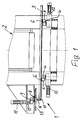
- Fig.1
- eine Ansicht einer nur teilweise dargestellten, im übrigen abgebrochen gezeichneten Presse, an welcher eine erfindungsgemäße Vorrichtung zum schrittweisen Vorschieben von Werkstücken angeordnet ist, die dabei in Seitenansicht dargestellt ist, wobei der zum Erfassen von Werkstücken dienende Teil der Greiferschienen innerhalb der Presse und ein Antrieb für den Vorschub der Greiferschienen außerhalb der Presse an dieser befestigt vorgesehen sind,
- Fig.2
- eine Draufsicht der Anordnung gemäß Fig.1, wobei Ständer der Presse oder dergleichen Bearbeitungsmaschine im Querschnitt erkennbar sind, und schwenkbare Hebel für die Bewegungen der Greiferschienen an diesen Ständern gelagert und für den Vorschub und die Rückzugsbewegung der Greiferschienen ebenfalls ein Schwenkhebel vorgesehen sind,
- Fig.3
- eine Stirnansicht der Anordnung gemäß Fig.1 und 2 etwa in Vorschubrichtung mit Blick auf einen von einem Servomotor angetriebenen Schwenkhebel und eine von diesem beaufschlagte Vorschubtraverse zum Verschieben der Greiferschienen in deren Längserstreckungsrichtung,
- Fig.4
- eine der Fig.2 entsprechende Darstellung mit zwei jeweils von einem Servomotor angetriebenen Schwenkhebel, die an einer gemeinsamen Vorschubtraverse zum Verstellen der Greiferschienen in deren Längserstreckungsrichtung angreifen und dabei gleich groß bemessen aber spiegelsymmetrisch zur Längsmittelebene zwischen den Greiferschienen angeordnet sind, sowie
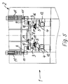
- Fig.5
- eine der Fig.3 entsprechende Darstellung mit Blick auf die beiden spiegelsymmetrisch angeordneten, an einer gemeinsamen Vorschubtraverse angreifenden, jeweils von einem Servomotor angetriebenen Schwenkhebel.
Claims (9)
- Vorrichtung (1) zum schrittweisen Vorschieben von Werkstücken mit zwei in Vorschubrichtung hin- und herbewegbaren, Greiferteile oder Greiferbereiche zum Erfassen der Werkstücke aufweisenden Greiferschienen (3), die zum Erfassen der Werkstücke und zum Bewegen in Vorschubrichtung bewegbar sind und anschließend wieder in Ausgangsstellung verstellbar sind, wobei an jeder Greiferschiene (3) wenigstens zwei parallel oder spiegelsynchron zueinander in der Bewegungsebene der Greiferschiene oder einer dazu parallelen Ebene verschwenkbare und zueinander beabstandete Hebel (4) angreifen und wobei diese Hebel (4) angreifen und wobei diese Hebel (4) der einen Greiferschiene (3) gegensinnig zu denen der anderen Greiferschiene (3) verschwenkbar und jeweils über eine in Orientierungsrichtung der Greiferschienen (3) verlaufende Längsführung (7) mit diesen gekuppelt sind, dadurch gekennzeichnet, dass für die Vorschub- und Rücklaufbewegung an den Greiferschienen (3) außerhalb ihrer Greifbereiche wenigstens eine quer zu sich selbst bewegbare Vorschubtraverse (8) direkt oder indirekt angreift, dass mit dieser Vorschubtraverse (8) wenigstens ein angetriebener Schwenkhebel (9) verbunden ist, dessen Schwenkbewegung in eine Vorschubbewegung der Vorschubtraverse (8) quer zu sich selbst und damit in eine Vorschubbewegung der Greiferschienen (3) sowie eine jeweilige Rücklaufbewegung umsetzbar ist, wobei die Angriffsstelle des Schwenkhebels (9) an einer in Orientierungsrichtung der Vorschubtraverse (8) verlaufende Längsführung (10) verschiebbar angreift, dass als Antrieb für die Schwenkbewegung des Schwenkhebels (9) ein Servomotor (11) vorgesehen ist und dass Mittel vorgesehen sind, um die Vorschubbewegung der Vorschubtraverse (8) quer oder parallel zu sich selbst zu führen.
- Vorrichtung nach Anspruch 1, dadurch gekennzeichnet, dass zur Führung der Vorschub- und Rücklaufbewegung der Vorschubtraverse (8) quer zu sich selbst zumindest eine mechanische Führung, beispielsweise wenigstens eine Führungsnut, ein Führungsprofil, eine Führungsschiene oder eine Führungstange vorgesehen ist, an der wenigstens ein an der Vorschubtraverse (8) vorhandenes Führungsstück oder Führungselement angreift, oder dass an der Vorschubtraverse (8) zumindest eine quer zu deren Erstreckung und in Orientierungsrichtung der Greiferschienen (3) verlaufende Führung vorgesehen ist, die mit wenigstens einem feststehenden Führungsstück oder Führungselement zusammenwirkt.
- Vorrichtung nach Anspruch 1 oder 2, dadurch gekennzeichnet, dass an der Vorschubtraverse (8) ein mit einem Servomotor (11) angetriebener zweiter Schwenkhebel (9) etwa spiegelsymmetrisch zu dem erstgenannten Schwenkhebel (9) und mit übereinstimmender Abmessung angreift, dessen Schwenkbewegung zusammen mit der des ersten Scwenkhebels (9) in die Vorschub- und Rücklaufbewegung einer jeweiligen oder der gemeinsamen Vorschubtraverse (8) und der Greiferschienen (3) umsetzbar ist, wobei die Angriffsstelle des zweiten Schwenkhebels (9) ebenfalls verschiebbar an einer in Orientierungsrichtung der zugehörigen Vorschubtraverse (8) verlaufenden Längsführung (10) angreift.
- Vorrichtung nach einem der Ansprüche 1 bis 3, dadurch gekennzeichnet, dass die Abtriebswelle (15) des Servomotors (11) mit der Schwenkachse des oder der Schwenkhebel (9) formschlüssig gekuppelt ist oder diese bildet.
- Vorrichtung nach einem der Ansprüche 1 bis 4, dadurch gekennzeichnet, dass die Vorschubtraverse (8) quer zu den Greiferschienen (3) an oder durch diese verlaufende Führungsaussparungen oder Führungsöffnungen durchsetzt und die Greiferschienen (3) bei ihren Öffnungs- und Schließbewegungen in Längsrichtung der Vorschubtraverse (8) quer zu dieser relativ bewegbar sind.
- Vorrichtung nach einem der Ansprüche 1 bis 5, dadurch gekennzeichnet, dass zur Koppelung der Vorschubtraverse (8) mit den Greiferschienen (3) an der Vorschubtraverse (8) in deren Orientierungsrichtung beispielsweise in Langlochungen verschiebbare Führungsfinger (16) oder dergleichen angeordnet sind, die sich von der Vorschubtraverse (8) aus in Gegenausnehmungen (17) der Greiferschienen (3) erstrecken.
- Vorrichtung nach einem der Ansprüche 1 bis 6, dadurch gekennzeichnet, dass die schwenkbaren Hebel (4) zum Bewegen der Greiferschienen (3) ober- und/oder unterhalb der Greiferschienen (3) und die Vorschubtraverse (8) sowie deren Schwenkhebel (9) unter- und/oder oberhalb der Greiferschienen (3) angeordnet sind.
- Vorrichtung nach einem der Ansprüche 1 bis 7, dadurch gekennzeichnet, dass die die Greiferschienen (3) beaufschlagenden Hebel (4) als Antrieb für ihre Schwenkbewegungen jeweils einen Servomotor (12) aufweisen und dass die Servomotoren (12) der schwenkbaren Hebel (4) für die Greiferschienen und des oder Schwenkhebel für die Vorschubtraverse (8) eine ihre Schwenkbewegungen, insbesondere zeitlich, aufeinander abstimmende gemeinsame Steuerung haben.
- Vorrichtung nach einem der Ansprüche 1 bis 8, dadurch gekennzeichnet, dass die schwenkbaren Hebel (4) und der die Schwenkhebel (9) jeweils mit ihren schwenkbaren Enden an Gleitsteinen angreifen, die in Langlochungen an den Greiferschienen (3) beziehungsweise an der Vorschubtraverse (8) verschiebbar und geführt eingreifen.
Applications Claiming Priority (2)
| Application Number | Priority Date | Filing Date | Title |
|---|---|---|---|
| DE10206773 | 2002-02-19 | ||
| DE10206773A DE10206773C1 (de) | 2002-02-19 | 2002-02-19 | Vorrichtung zum Vorschieben von Werkstücken mit Greiferschienen |
Publications (2)
| Publication Number | Publication Date |
|---|---|
| EP1336440A1 true EP1336440A1 (de) | 2003-08-20 |
| EP1336440B1 EP1336440B1 (de) | 2010-03-03 |
Family
ID=27618757
Family Applications (1)
| Application Number | Title | Priority Date | Filing Date |
|---|---|---|---|
| EP03001584A Expired - Lifetime EP1336440B1 (de) | 2002-02-19 | 2003-01-24 | Vorrichtung zum Vorschieben von Werkstücken mit Greiferschienen |
Country Status (6)
| Country | Link |
|---|---|
| US (1) | US6702098B2 (de) |
| EP (1) | EP1336440B1 (de) |
| AT (1) | ATE459438T1 (de) |
| CA (1) | CA2419195C (de) |
| DE (2) | DE10206773C1 (de) |
| ES (1) | ES2342265T3 (de) |
Cited By (3)
| Publication number | Priority date | Publication date | Assignee | Title |
|---|---|---|---|---|
| WO2008058496A1 (de) * | 2006-11-08 | 2008-05-22 | Müller Weingarten AG | Transfervorrichtung für eine presse |
| WO2009083104A3 (de) * | 2007-12-29 | 2009-11-05 | Erdrich Beteiligungs Gmbh | Presse zum formen von werkstücken |
| CN103668378A (zh) * | 2012-08-31 | 2014-03-26 | 鸿富锦精密工业(深圳)有限公司 | 上料设备 |
Families Citing this family (13)
| Publication number | Priority date | Publication date | Assignee | Title |
|---|---|---|---|---|
| DE102004023525B4 (de) * | 2004-05-13 | 2006-07-20 | Erdrich Beteiligungs Gmbh | Vorrichtung zum schrittweisen Verschieben von Werkstücken |
| DE102007009747B4 (de) * | 2007-02-28 | 2009-01-29 | Siemens Ag | Transfersystem |
| US9114936B2 (en) * | 2011-08-29 | 2015-08-25 | Yokota Technica Limited Company | Conveyor apparatus |
| AT515198B1 (de) * | 2014-02-07 | 2015-07-15 | Springer Maschinenfabrik Ag | Zuteiler zum Zuteilen von Schnittholzteilen |
| DE102015002496B4 (de) | 2015-02-27 | 2016-09-22 | Sander Automation Gmbh | Vorrichtung zum schrittweisen Vorschieben von Werkstücken |
| CN107598269A (zh) * | 2017-10-30 | 2018-01-19 | 辽宁忠旺机械设备制造有限公司 | 铝母线成型加工复合锯 |
| CN108407865B (zh) * | 2018-05-11 | 2024-11-05 | 安妥驰(张家港)汽车零部件再制造有限公司 | 通用型汽车发动机测试用对接小车 |
| CN109365299B (zh) * | 2018-10-17 | 2024-02-23 | 顺丰科技有限公司 | 传输装置、传输线以及分拣设备 |
| CN111112460B (zh) * | 2020-01-09 | 2025-10-14 | 温州创睿五金模具有限公司 | 一种机械手联动的压铸模具 |
| JP7180895B2 (ja) * | 2020-07-22 | 2022-11-30 | ヒーハイスト株式会社 | 位置決めテーブル |
| CN112620830B (zh) * | 2020-12-28 | 2022-02-11 | 宁波爱柯迪精密部件有限公司 | 工件输送机构和内螺纹加工设备 |
| CN113681336B (zh) * | 2021-07-23 | 2023-04-14 | 嘉兴晟友机械科技有限公司 | 一种机床的双向物料上料装置 |
| CN113894524B (zh) * | 2021-11-17 | 2024-05-31 | 广州珠江恺撒堡钢琴有限公司 | 联动杆与托木丝自动化装配装置 |
Citations (4)
| Publication number | Priority date | Publication date | Assignee | Title |
|---|---|---|---|---|
| DE2740211A1 (de) * | 1977-09-07 | 1979-03-08 | Schuler Gmbh L | Vorrichtung zum antreiben eines paares greiferschienen in laengsrichtung |
| EP0633077A1 (de) * | 1993-05-08 | 1995-01-11 | FIRMA SANDER KG GmbH & Co. | Vorrichtung zum schrittweisen Vorschieben von Werkstücken |
| US6216523B1 (en) | 1999-10-20 | 2001-04-17 | Hms Products Co. | Servo-drive for press transfer |
| DE10019109A1 (de) | 2000-04-18 | 2001-10-25 | Sander Kg Gmbh & Co | Umformpresse mit wenigstens einem Stufenwerkzeug und mit einem Greifervorschubgerät |
Family Cites Families (4)
| Publication number | Priority date | Publication date | Assignee | Title |
|---|---|---|---|---|
| US5004093A (en) * | 1989-11-08 | 1991-04-02 | Charles Packaging Corporation | Straight line sorting and/or fill-to-weigh machine |
| ES2101075T3 (es) * | 1991-11-13 | 1997-07-01 | Ciba Geigy Ag | Dispositivo de recubrimiento para placas. |
| JP2002514558A (ja) * | 1998-05-04 | 2002-05-21 | バンティコ アクチエンゲゼルシャフト | 薄板、特に印刷回路板を移送するための装置 |
| JP3895054B2 (ja) * | 1998-08-19 | 2007-03-22 | 株式会社小松製作所 | トランスファプレス機におけるトランスファフィーダの3次元駆動装置 |
-
2002
- 2002-02-19 DE DE10206773A patent/DE10206773C1/de not_active Expired - Lifetime
-
2003
- 2003-01-24 DE DE50312464T patent/DE50312464D1/de not_active Expired - Lifetime
- 2003-01-24 AT AT03001584T patent/ATE459438T1/de not_active IP Right Cessation
- 2003-01-24 EP EP03001584A patent/EP1336440B1/de not_active Expired - Lifetime
- 2003-01-24 ES ES03001584T patent/ES2342265T3/es not_active Expired - Lifetime
- 2003-02-19 US US10/368,832 patent/US6702098B2/en not_active Expired - Lifetime
- 2003-02-19 CA CA002419195A patent/CA2419195C/en not_active Expired - Lifetime
Patent Citations (5)
| Publication number | Priority date | Publication date | Assignee | Title |
|---|---|---|---|---|
| DE2740211A1 (de) * | 1977-09-07 | 1979-03-08 | Schuler Gmbh L | Vorrichtung zum antreiben eines paares greiferschienen in laengsrichtung |
| EP0633077A1 (de) * | 1993-05-08 | 1995-01-11 | FIRMA SANDER KG GmbH & Co. | Vorrichtung zum schrittweisen Vorschieben von Werkstücken |
| EP0633077B1 (de) | 1993-05-08 | 1997-03-19 | FIRMA SANDER KG GmbH & Co. | Vorrichtung zum schrittweisen Vorschieben von Werkstücken |
| US6216523B1 (en) | 1999-10-20 | 2001-04-17 | Hms Products Co. | Servo-drive for press transfer |
| DE10019109A1 (de) | 2000-04-18 | 2001-10-25 | Sander Kg Gmbh & Co | Umformpresse mit wenigstens einem Stufenwerkzeug und mit einem Greifervorschubgerät |
Cited By (5)
| Publication number | Priority date | Publication date | Assignee | Title |
|---|---|---|---|---|
| WO2008058496A1 (de) * | 2006-11-08 | 2008-05-22 | Müller Weingarten AG | Transfervorrichtung für eine presse |
| CN101563176B (zh) * | 2006-11-08 | 2012-03-21 | 穆勒魏恩加滕股份公司 | 用于压机的传送装置 |
| WO2009083104A3 (de) * | 2007-12-29 | 2009-11-05 | Erdrich Beteiligungs Gmbh | Presse zum formen von werkstücken |
| CN103668378A (zh) * | 2012-08-31 | 2014-03-26 | 鸿富锦精密工业(深圳)有限公司 | 上料设备 |
| CN103668378B (zh) * | 2012-08-31 | 2016-04-13 | 鸿富锦精密工业(深圳)有限公司 | 上料设备 |
Also Published As
| Publication number | Publication date |
|---|---|
| DE50312464D1 (de) | 2010-04-15 |
| ES2342265T3 (es) | 2010-07-05 |
| US6702098B2 (en) | 2004-03-09 |
| US20030183485A1 (en) | 2003-10-02 |
| CA2419195C (en) | 2009-10-27 |
| CA2419195A1 (en) | 2003-08-19 |
| DE10206773C1 (de) | 2003-10-02 |
| ATE459438T1 (de) | 2010-03-15 |
| EP1336440B1 (de) | 2010-03-03 |
Similar Documents
| Publication | Publication Date | Title |
|---|---|---|
| EP1336440B1 (de) | Vorrichtung zum Vorschieben von Werkstücken mit Greiferschienen | |
| EP3370892B1 (de) | Greifersystem für eine biegepresse | |
| DE2039697C3 (de) | Mehrstufige Formmaschine, insbesondere Mehrstufenpresse | |
| DE102017207585B4 (de) | Drahtumformmaschine und Verfahren zur Herstellung von Umformteilen aus Draht | |
| DE2411744C3 (de) | Presse zum Pressverbinden eines Kabels oder isolierten Drahtes mit einem Kabelschuh | |
| DE202020002598U1 (de) | Biegemaschine zum Biegen eines Werkstücks aus Flachmaterial und Steuereinheit für eine solche Biegemaschine | |
| EP1640084B1 (de) | Vorschubvorrichtung | |
| EP1682289A1 (de) | Gelenkarmtransportvorrichtung | |
| EP0633077B1 (de) | Vorrichtung zum schrittweisen Vorschieben von Werkstücken | |
| EP1748855B1 (de) | Vorrichtung zum schrittweisen verschieben von werkstücken | |
| EP2192067B1 (de) | Stapelvorrichtung für Druckprodukte | |
| DE10059312C2 (de) | Zentriervorrichtung für Fördergut | |
| WO1998009743A1 (de) | Bearbeitungsmaschine für plattenförmige werkstücke mit einem in einzelne segmente unterteilten niederhalter | |
| DE2525616B2 (de) | Verstellvorrichtung einer Werkstücktransporteinrichtung von Stufenpressen K.K. Komatsu Seisakusho, Tokio | |
| DE2206407B2 (de) | Vorschubeinrichtung in Pressen | |
| DE2804107A1 (de) | Verfahren und einrichtung zur verbindung aneinanderliegender materialschichten | |
| DE10065255B4 (de) | Mehrstufenpresse | |
| DE4320431B4 (de) | Transferpressenkomplex | |
| DE69703978T2 (de) | Vorrichtung zum regeln der grösse eines werkzeugmaschinen-blechhalters | |
| DE10063154B4 (de) | Schmiedepresse mit Stellvorrichtung auf Matrizenseite | |
| EP0699786A2 (de) | Fachbildungsvorrichtung | |
| DE10128189A1 (de) | Transport- und/oder Lagerungsvorrichtung für Werkstücke | |
| DE102012110661B4 (de) | Kurvenschiene für ein Transfersystem, sowie Umformautomat | |
| DE4304902A1 (de) | Vorschubeinrichtung zum schrittweisen Material- und/oder Werkstücktransport an bzw. in Produktionsmaschinen, wie Ziehpressen | |
| EP0873205B1 (de) | Biegemaschine |
Legal Events
| Date | Code | Title | Description |
|---|---|---|---|
| PUAI | Public reference made under article 153(3) epc to a published international application that has entered the european phase |
Free format text: ORIGINAL CODE: 0009012 |
|
| AK | Designated contracting states |
Designated state(s): AT BE BG CH CY CZ DE DK EE ES FI FR GB GR HU IE IT LI LU MC NL PT SE SI SK TR |
|
| AX | Request for extension of the european patent |
Extension state: AL LT LV MK RO |
|
| 17P | Request for examination filed |
Effective date: 20030816 |
|
| AKX | Designation fees paid |
Designated state(s): AT BE BG CH CY CZ DE DK EE ES FI FR GB GR HU IE IT LI LU MC NL PT SE SI SK TR |
|
| 17Q | First examination report despatched |
Effective date: 20081117 |
|
| GRAP | Despatch of communication of intention to grant a patent |
Free format text: ORIGINAL CODE: EPIDOSNIGR1 |
|
| RIN1 | Information on inventor provided before grant (corrected) |
Inventor name: NOCK, KLEMENS Inventor name: ZEIBIG, UWE |
|
| GRAS | Grant fee paid |
Free format text: ORIGINAL CODE: EPIDOSNIGR3 |
|
| GRAA | (expected) grant |
Free format text: ORIGINAL CODE: 0009210 |
|
| AK | Designated contracting states |
Kind code of ref document: B1 Designated state(s): AT BE BG CH CY CZ DE DK EE ES FI FR GB GR HU IE IT LI LU MC NL PT SE SI SK TR |
|
| REG | Reference to a national code |
Ref country code: GB Ref legal event code: FG4D Free format text: NOT ENGLISH |
|
| REG | Reference to a national code |
Ref country code: CH Ref legal event code: EP |
|
| REG | Reference to a national code |
Ref country code: IE Ref legal event code: FG4D |
|
| REF | Corresponds to: |
Ref document number: 50312464 Country of ref document: DE Date of ref document: 20100415 Kind code of ref document: P |
|
| REG | Reference to a national code |
Ref country code: NL Ref legal event code: VDEP Effective date: 20100303 |
|
| REG | Reference to a national code |
Ref country code: ES Ref legal event code: FG2A Ref document number: 2342265 Country of ref document: ES Kind code of ref document: T3 |
|
| PG25 | Lapsed in a contracting state [announced via postgrant information from national office to epo] |
Ref country code: SI Free format text: LAPSE BECAUSE OF FAILURE TO SUBMIT A TRANSLATION OF THE DESCRIPTION OR TO PAY THE FEE WITHIN THE PRESCRIBED TIME-LIMIT Effective date: 20100303 Ref country code: FI Free format text: LAPSE BECAUSE OF FAILURE TO SUBMIT A TRANSLATION OF THE DESCRIPTION OR TO PAY THE FEE WITHIN THE PRESCRIBED TIME-LIMIT Effective date: 20100303 |
|
| REG | Reference to a national code |
Ref country code: IE Ref legal event code: FD4D |
|
| PG25 | Lapsed in a contracting state [announced via postgrant information from national office to epo] |
Ref country code: SE Free format text: LAPSE BECAUSE OF FAILURE TO SUBMIT A TRANSLATION OF THE DESCRIPTION OR TO PAY THE FEE WITHIN THE PRESCRIBED TIME-LIMIT Effective date: 20100303 Ref country code: NL Free format text: LAPSE BECAUSE OF FAILURE TO SUBMIT A TRANSLATION OF THE DESCRIPTION OR TO PAY THE FEE WITHIN THE PRESCRIBED TIME-LIMIT Effective date: 20100303 Ref country code: IE Free format text: LAPSE BECAUSE OF FAILURE TO SUBMIT A TRANSLATION OF THE DESCRIPTION OR TO PAY THE FEE WITHIN THE PRESCRIBED TIME-LIMIT Effective date: 20100303 Ref country code: GR Free format text: LAPSE BECAUSE OF FAILURE TO SUBMIT A TRANSLATION OF THE DESCRIPTION OR TO PAY THE FEE WITHIN THE PRESCRIBED TIME-LIMIT Effective date: 20100604 Ref country code: EE Free format text: LAPSE BECAUSE OF FAILURE TO SUBMIT A TRANSLATION OF THE DESCRIPTION OR TO PAY THE FEE WITHIN THE PRESCRIBED TIME-LIMIT Effective date: 20100303 Ref country code: CY Free format text: LAPSE BECAUSE OF FAILURE TO SUBMIT A TRANSLATION OF THE DESCRIPTION OR TO PAY THE FEE WITHIN THE PRESCRIBED TIME-LIMIT Effective date: 20100303 |
|
| PG25 | Lapsed in a contracting state [announced via postgrant information from national office to epo] |
Ref country code: SK Free format text: LAPSE BECAUSE OF FAILURE TO SUBMIT A TRANSLATION OF THE DESCRIPTION OR TO PAY THE FEE WITHIN THE PRESCRIBED TIME-LIMIT Effective date: 20100303 Ref country code: CZ Free format text: LAPSE BECAUSE OF FAILURE TO SUBMIT A TRANSLATION OF THE DESCRIPTION OR TO PAY THE FEE WITHIN THE PRESCRIBED TIME-LIMIT Effective date: 20100303 Ref country code: BG Free format text: LAPSE BECAUSE OF FAILURE TO SUBMIT A TRANSLATION OF THE DESCRIPTION OR TO PAY THE FEE WITHIN THE PRESCRIBED TIME-LIMIT Effective date: 20100603 |
|
| PLBE | No opposition filed within time limit |
Free format text: ORIGINAL CODE: 0009261 |
|
| STAA | Information on the status of an ep patent application or granted ep patent |
Free format text: STATUS: NO OPPOSITION FILED WITHIN TIME LIMIT |
|
| PG25 | Lapsed in a contracting state [announced via postgrant information from national office to epo] |
Ref country code: PT Free format text: LAPSE BECAUSE OF FAILURE TO SUBMIT A TRANSLATION OF THE DESCRIPTION OR TO PAY THE FEE WITHIN THE PRESCRIBED TIME-LIMIT Effective date: 20100705 Ref country code: DK Free format text: LAPSE BECAUSE OF FAILURE TO SUBMIT A TRANSLATION OF THE DESCRIPTION OR TO PAY THE FEE WITHIN THE PRESCRIBED TIME-LIMIT Effective date: 20100303 |
|
| 26N | No opposition filed |
Effective date: 20101206 |
|
| PG25 | Lapsed in a contracting state [announced via postgrant information from national office to epo] |
Ref country code: MC Free format text: LAPSE BECAUSE OF NON-PAYMENT OF DUE FEES Effective date: 20110131 |
|
| REG | Reference to a national code |
Ref country code: CH Ref legal event code: PL |
|
| PG25 | Lapsed in a contracting state [announced via postgrant information from national office to epo] |
Ref country code: CH Free format text: LAPSE BECAUSE OF NON-PAYMENT OF DUE FEES Effective date: 20110131 Ref country code: LI Free format text: LAPSE BECAUSE OF NON-PAYMENT OF DUE FEES Effective date: 20110131 |
|
| REG | Reference to a national code |
Ref country code: AT Ref legal event code: MM01 Ref document number: 459438 Country of ref document: AT Kind code of ref document: T Effective date: 20110124 |
|
| PG25 | Lapsed in a contracting state [announced via postgrant information from national office to epo] |
Ref country code: AT Free format text: LAPSE BECAUSE OF NON-PAYMENT OF DUE FEES Effective date: 20110124 |
|
| PGFP | Annual fee paid to national office [announced via postgrant information from national office to epo] |
Ref country code: BE Payment date: 20121128 Year of fee payment: 11 |
|
| PG25 | Lapsed in a contracting state [announced via postgrant information from national office to epo] |
Ref country code: LU Free format text: LAPSE BECAUSE OF NON-PAYMENT OF DUE FEES Effective date: 20110124 |
|
| PG25 | Lapsed in a contracting state [announced via postgrant information from national office to epo] |
Ref country code: TR Free format text: LAPSE BECAUSE OF FAILURE TO SUBMIT A TRANSLATION OF THE DESCRIPTION OR TO PAY THE FEE WITHIN THE PRESCRIBED TIME-LIMIT Effective date: 20100303 |
|
| PG25 | Lapsed in a contracting state [announced via postgrant information from national office to epo] |
Ref country code: HU Free format text: LAPSE BECAUSE OF FAILURE TO SUBMIT A TRANSLATION OF THE DESCRIPTION OR TO PAY THE FEE WITHIN THE PRESCRIBED TIME-LIMIT Effective date: 20100303 |
|
| BERE | Be: lapsed |
Owner name: ERDRICH BETEILIGUNGS G.M.B.H. Effective date: 20140131 |
|
| PG25 | Lapsed in a contracting state [announced via postgrant information from national office to epo] |
Ref country code: BE Free format text: LAPSE BECAUSE OF NON-PAYMENT OF DUE FEES Effective date: 20140131 |
|
| REG | Reference to a national code |
Ref country code: FR Ref legal event code: PLFP Year of fee payment: 14 |
|
| REG | Reference to a national code |
Ref country code: FR Ref legal event code: PLFP Year of fee payment: 15 |
|
| REG | Reference to a national code |
Ref country code: FR Ref legal event code: PLFP Year of fee payment: 16 |
|
| PGFP | Annual fee paid to national office [announced via postgrant information from national office to epo] |
Ref country code: DE Payment date: 20200129 Year of fee payment: 18 |
|
| PGFP | Annual fee paid to national office [announced via postgrant information from national office to epo] |
Ref country code: IT Payment date: 20210129 Year of fee payment: 19 Ref country code: FR Payment date: 20210121 Year of fee payment: 19 |
|
| PGFP | Annual fee paid to national office [announced via postgrant information from national office to epo] |
Ref country code: GB Payment date: 20210122 Year of fee payment: 19 Ref country code: ES Payment date: 20210217 Year of fee payment: 19 |
|
| REG | Reference to a national code |
Ref country code: DE Ref legal event code: R119 Ref document number: 50312464 Country of ref document: DE |
|
| PG25 | Lapsed in a contracting state [announced via postgrant information from national office to epo] |
Ref country code: DE Free format text: LAPSE BECAUSE OF NON-PAYMENT OF DUE FEES Effective date: 20210803 |
|
| GBPC | Gb: european patent ceased through non-payment of renewal fee |
Effective date: 20220124 |
|
| PG25 | Lapsed in a contracting state [announced via postgrant information from national office to epo] |
Ref country code: GB Free format text: LAPSE BECAUSE OF NON-PAYMENT OF DUE FEES Effective date: 20220124 |
|
| PG25 | Lapsed in a contracting state [announced via postgrant information from national office to epo] |
Ref country code: FR Free format text: LAPSE BECAUSE OF NON-PAYMENT OF DUE FEES Effective date: 20220131 |
|
| PG25 | Lapsed in a contracting state [announced via postgrant information from national office to epo] |
Ref country code: IT Free format text: LAPSE BECAUSE OF NON-PAYMENT OF DUE FEES Effective date: 20220124 |
|
| REG | Reference to a national code |
Ref country code: ES Ref legal event code: FD2A Effective date: 20230301 |
|
| PG25 | Lapsed in a contracting state [announced via postgrant information from national office to epo] |
Ref country code: ES Free format text: LAPSE BECAUSE OF NON-PAYMENT OF DUE FEES Effective date: 20220125 |