EP1333428A1 - Mechanismus zur genauen Spurverfolgung eines Plattenschreib- und Lesekopfes und Plattenlaufwerk mit diesem Mechanismus - Google Patents
Mechanismus zur genauen Spurverfolgung eines Plattenschreib- und Lesekopfes und Plattenlaufwerk mit diesem Mechanismus Download PDFInfo
- Publication number
- EP1333428A1 EP1333428A1 EP02027845A EP02027845A EP1333428A1 EP 1333428 A1 EP1333428 A1 EP 1333428A1 EP 02027845 A EP02027845 A EP 02027845A EP 02027845 A EP02027845 A EP 02027845A EP 1333428 A1 EP1333428 A1 EP 1333428A1
- Authority
- EP
- European Patent Office
- Prior art keywords
- base
- suspension
- piezoelectric
- piezoelectric element
- pair
- Prior art date
- Legal status (The legal status is an assumption and is not a legal conclusion. Google has not performed a legal analysis and makes no representation as to the accuracy of the status listed.)
- Withdrawn
Links
Images


Classifications
-
- G—PHYSICS
- G11—INFORMATION STORAGE
- G11B—INFORMATION STORAGE BASED ON RELATIVE MOVEMENT BETWEEN RECORD CARRIER AND TRANSDUCER
- G11B5/00—Recording by magnetisation or demagnetisation of a record carrier; Reproducing by magnetic means; Record carriers therefor
- G11B5/48—Disposition or mounting of heads or head supports relative to record carriers ; arrangements of heads, e.g. for scanning the record carrier to increase the relative speed
- G11B5/56—Disposition or mounting of heads or head supports relative to record carriers ; arrangements of heads, e.g. for scanning the record carrier to increase the relative speed with provision for moving the head support for the purpose of adjusting the position of the head relative to the record carrier, e.g. manual adjustment for azimuth correction or track centering
-
- G—PHYSICS
- G11—INFORMATION STORAGE
- G11B—INFORMATION STORAGE BASED ON RELATIVE MOVEMENT BETWEEN RECORD CARRIER AND TRANSDUCER
- G11B5/00—Recording by magnetisation or demagnetisation of a record carrier; Reproducing by magnetic means; Record carriers therefor
- G11B5/48—Disposition or mounting of heads or head supports relative to record carriers ; arrangements of heads, e.g. for scanning the record carrier to increase the relative speed
- G11B5/54—Disposition or mounting of heads or head supports relative to record carriers ; arrangements of heads, e.g. for scanning the record carrier to increase the relative speed with provision for moving the head into or out of its operative position or across tracks
- G11B5/55—Track change, selection or acquisition by displacement of the head
- G11B5/5521—Track change, selection or acquisition by displacement of the head across disk tracks
- G11B5/5552—Track change, selection or acquisition by displacement of the head across disk tracks using fine positioning means for track acquisition separate from the coarse (e.g. track changing) positioning means
Definitions
- TPI Track per Inch
- the conventional shear type piezoelectric actuator barely enlarges the minutely deformed amount (or stroke).
- an actuator that uses a longitudinal effect of the piezoelectric element may enlarge the stroke, but it is difficult to layer the shear type element for manufacturing reasons and thus hard to provide a sufficiently large stroke.
- Access to a track beyond fine positioning requires driving by a voice coil motor, resulting in a low head positioning speed.
- a large stroke for fine tracking purposes shortens the time period necessary for settling (which is a setting operation to a target position in a head positioning operation), and effectively provides faster settling.
- a small fine tracking stroke is likely to be saturated under a strong disturbance, such as external vibrations, and cannot provide desired compensation.
- the arm swings around a rotary shaft, and the suspension supports a head.
- a drive part is located adjacent the base for deforming the base, the drive part including a shear type piezoelectric element that is polarized in a direction orthogonal to a thickness direction of the piezoelectric element.
- the drive part deforms top and bottom surfaces of the piezoelectric element perpendicular to the thickness direction when voltage is applied to the piezoelectric element in the thickness direction.
- the base in this fine tracking mechanism serves as a hinge plate, and reduces attachment tolerance of the suspension.
- the reduced distribution within the suspension's attachment tolerance means that the suspension may be attached with more precision close to its design value. Therefore, the elastic force, for example, as seen in a contact start stop system where a suspension applies a preset elastic force to a disc, more closely approaches the design value, preventing crash and improving positioning accuracy.
- the base that serves as a hinge plate contributes to the reduced number of components, low profile, and cost reduction of the fine tracking mechanism.
- the drive part may be provided at a first side of the base, and the suspension may be provided at a second side of the base opposite to the first side. Since no drive part exists between the suspension and the base, the suspension's attachment tolerance depends only upon the thickness tolerance and flatness of the base, and is not subject to the additional dimension tolerance introduced by the drive part. As a result, the suspension's attachment tolerance may be further reduced.
- Two pairs of shear type piezoelectric elements are provided for finely adjusting the suspension position, the shear type piezoelectric elements being polarized in a direction orthogonal to a thickness direction of the piezoelectric elements, and deforming top and bottom surfaces of the piezoelectric elements, perpendicular to the thickness direction when voltage is applied to the piezoelectric elements in the thickness direction.
- An electrode layer may be formed on the base through an insulating layer, the electrode layer being used to apply voltage to the shear type piezoelectric element. In this manner, the dispersion of the suspension's attachment tolerance may be reduced, in comparison with the conventional structure in which an additional electrode plate is formed as a separate member from the base and the suspension is provided above the electrode plate.
- the base may be grounded. Since the base serves partially to apply voltage to the piezoelectric element, the suspension's attachment tolerance may be reduced in comparison with such a structure in which an additional electrode plat is formed as a separate member from the base.
- the base may be grounded, desired voltage may be applied to the piezoelectric-element coupling plate, and two pairs of shear type piezoelectric elements may be bonded onto the base.
- the suspension's attachment tolerance may be further reduced, in comparison with the conventional structure in which an additional electrode plate is formed as a separate member from the base and the suspension is provided above the electrode plate.
- this invention provides the easier manufacture and cost reduction since it is unnecessary to form the insulating and electrode layers.
- a pair of piezoelectric-element coupling plates may be connected to each other through a flexible part, thereby maintaining free deformations of each piezoelectric-element coupling plate.
- a pair of piezoelectric-element coupling plates may serve as an electrode that applies voltage to the piezoelectric elements, thereby contributing to easier manufacture and cost reduction in comparison with a structure in which an additional electrode plate is formed as a separate member from a base.
- Each pair of piezoelectric-element coupling plates may expose part of the shear type piezoelectric element, and an exposed part of the piezoelectric element may be wire-connected to a junction part with a wire pattern for driving the arm. Thereby, the wire pattern controls both driving of the arm and fine positioning of the suspension.
- An actuator and a disc drive include the above fine tracking mechanism, and exhibit the operations of the above tracking mechanism.
- the reduced distribution of the suspension's attachment tolerance would be helpful particularly when the disc drive drives plural discs. This is because when the suspension's attachment tolerance becomes larger than the design value, it becomes difficult to accommodate a predetermined number of discs in the disc drive having a predetermined thickness.
- the housing can be made, for example, of aluminum die casting or stainless steel, and has a rectangular parallelepiped shape to which a cover (not shown) is coupled so as to seal its internal space.
- Each magnetic disc 13 in this embodiment has high recording density, such as 100 Gb/in 2 or even higher, and is mounted on a spindle of the spindle motor 14.
- the spindle motor 14 rotates the magnetic disc 13 at a high speed, such as 7,200 rpm and 10,000 rpm, and includes a brushless DC motor (not shown) and a spindle as its rotor part.
- a brushless DC motor not shown
- a spindle as its rotor part.
- the magnetic disc 13 may be a disc having a hub without a center hole, and the spindle rotates the disc through the hub.
- the magnetic head part includes a slider 19, and an actuator 100 that serves as a mechanism for positioning and driving the slider 19.
- the slider 19 includes, as shown in FIG. 2, a slider body 22 having an approximately rectangular parallelepiped shape made of Al 2 O 3 -TiC (altic), and a head-device built-in film 24 secured at an air outflow end of the slider body 22 and made of Al 2 O 3 (alumina), the film 24 including a built-in read/write head 23.
- FIG. 2 is an enlarged perspective view of the slider 19.
- the slider body 22 and head-device built-in film 24 define a floatation surface 25 as a surface opposite to a carrier, i.e ., the magnetic disc 13, which surface 25 catches air current 26 generated from the rotating magnetic disc 13.
- a pair of rails 27 are formed on the floatation surface 25, extending from an air inflow end to the air outflow end.
- a so-called air-bearing surface (referred to as "ABS" hereinafter) 28 is defined at a top ( i.e ., outer) surface of each rail 27.
- the buoyancy is generated at the ABS 28 by the air current 26.
- the head 23 embedded in the head-device built-in film 24 is exposed at the ABS 28.
- the floatation system of the slider 19 is not limited to this form, but may use a known dynamic pressure lubricating system, a known static pressure lubricating system, a known piezoelectric control system, and any other known floatation system.
- the slider 19 may be lifted up over the disc 13 before the disc 13 stops, held at a holding part (sometimes referred to as a ramp) located outside the disc 13 so as to hold the slider 19 in a non-contact manner with the disc 13, and dropped from the holding part over the disc 13 when the disc 13 runs, as in the dynamic or ramp loading system.
- a holding part sometimes referred to as a ramp
- the voice coil motor includes a flat coil 34 between two yokes 32 at one side with respect to the support shaft 15.
- the flat coil 34 is provided opposite to a magnetic circuit (not shown) provided in the housing 12 of the HDD 11, and actuator 100 swings in accordance with a current value flowing in the flat coil 34.
- the magnetic circuit includes, for example, a permanent magnet fixed onto an iron plate fixed in the housing 12, and a mobile magnet fixed onto the carriage 16.
- the support shaft 15 is inserted into a cylindrical hollow hole in the carriage 16, and arranged such that it extends perpendicular to the paper surface in FIG. 1 in the housing 12.
- the carriage 16 includes plural (e.g., four) rigid arms 17 each operable rotatably or swingably around the support shaft 15, plural (e.g., six) suspensions 18 each of which is attached to a tip of the corresponding arm 17 and extends forward from the arm 17, and plural (e.g., four) bases 41 each of which connects the suspension 18 to the arm 17.
- the base 41 constitutes a fine tracking mechanism 40 which will be described with reference to FIGs. 4A and 4B.
- the arm 17 has a pectinate shape viewed from a side at one side with respect to the support shaft 15.
- the suspension 18 can be, for example, a Watlas type suspension made of stainless steel, which uses a gimbal spring (not shown) to cantilever the slider 19,
- the suspension 18 also supports a wiring part 18a connected to the slider 19 through a lead, etc.
- the wiring part 18a is depicted in FIGs. 4A, which will be described later.
- the sense current, read-in data, and read-out data are supplied and output between the head 23 and the wiring part 18a through such a lead.
- the wiring part 18a is connected to a junction flexible printed circuit ("FPC") board 30.
- FPC junction flexible printed circuit
- the suspension 18 applies an elastic force to the slider 19 against a surface of the magnetic disc 13.
- the instant embodiment reduces the attachment tolerance of the suspension 18 to a surface of the arm 17 as compared with prior art structures, and thus the dispersed elastic force which the suspension 18 applies to the slider 19 is almost always within a permissible designed range.
- the flatness of each of the suspension 18 and the slider 19 is improved in comparison with the prior art structures, thereby preventing head crash and lowered positioning accuracy under excessive elastic force and torsion.
- FIG. 4A is an enlarged plan view of the fine tracking mechanism 40 for the actuator 100
- FIG. 4B is a schematic side view of FIG. 4A
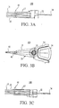
- FIG. 5A is an enlarged plan view of the base 41 shown in FIGs. 4A and 4B
- FIG. 5B is a schematic side view of FIG. 5A.
- the fine adjustment mechanism 40 includes the base 41, two pairs of piezoelectric elements 42a-42d (which are generalized by reference numeral 42), an insulating layer 43, a conductive layer 44, a piezoelectric-element coupling plate 45, a caulking part 46, and a connecting part 47.
- the base 41 is fixed onto the arm 17 which swings around the support shaft 15, and the suspension 18 which supports the slider 19.
- the base 41 connects the suspension 18 to the slider 19.
- the base 41 is fixed onto the arm 17 via a caulking part 46.
- the base 41 has slits 41a-41c, as shown in FIG. 5A in which the piezoelectric-element coupling plate 45 is removed from FIG. 4A.
- the slits 41a and 41c are formed in a direction perpendicular to a longitudinal direction L of the base 41, near a centerline C in the base 41, while the slit 41b forms a T shape symmetrical with respect to the centerline C.
- the slits 41a-41c allow the base 41 to include a mobile part 41d which secures the suspension 18 and may move minutely with the suspension 18, a mobile part 41e which mounts piezoelectric elements 42a and 42c at the side of the mobile part 41d, and a fixed part 41f which is connected to the arm 17 side and mounts the piezoelectric elements 42b and 42d.
- the mobile parts 41d and 41e are movable relative to the fixed part 41f.
- the base 41 of this embodiment has the mobile part 41d that may finely move the suspension 18, and serves as a conventional hinge plate.
- the attachment tolerance of the suspension 18 is affected by hinge plate's dimension tolerance, but the instant embodiment removes the hinge plate between the base 41 and the suspension 18 and reduces the dispersion of the attachment tolerance of the suspension 18 in comparison with a structure in which the hinge plate is located between them.
- the HDD 11 may accommodate plural discs 13.
- the suspension's attachment tolerance exceeds a design value, it becomes difficult to accommodate a predetermined number of discs 13 in the disc drive having a predetermined thickness.
- the reduced attachment tolerance of the suspension would be helpful particularly when the HDD 11 drives a plurality of discs.
- the reduced dispersion in the suspension's attachment tolerance means that the suspension may be attached with precision closer to a design value. Therefore, the elastic force, for example, as seen in a contact start stop system where the suspension 18 applies a preset elastic force to the disc 13, comes close to the design value, preventing head crash and improving positioning accuracy.
- the base 41 that serves as a hinge plate contributes to the reduced number of components, low profile, and cost reduction of the fine positioning mechanism 40.
- the piezoelectric element 42 is a shear type piezoelectric element that is polarized in a direction orthogonal to its thickness direction, and deforms its top and bottom surfaces perpendicular to the thickness direction when voltage is applied to the piezoelectric element 42 in the thickness direction.
- the shear type piezoelectric element shears or sliding deformation when voltage is applied to its top and bottom surfaces. Therefore, when voltage is applied while one electrode is mounted, for example, on a bottom surface and the other electrode is mounted, for example, on a top surface, it deforms in the polarization direction.
- the piezoelectric element 42 is provided on the base 41, and deforms the mobile parts 41d and 41e in the base 41 through the slits 41a-41c.
- a Cu/Ar film is formed through sputtering at the top and bottom surfaces of the piezoelectric element 42.
- the attachment tolerance of the suspension 18 to the arm 17's surface depends only upon the thickness tolerance and the flatness of the base 41, and is not affected by dimensions of the piezoelectric element 42 or any other component (e.g., the piezoelectric-element coupling plate 45) (which is coupled with a top side shown in FIG. 4B) of the piezoelectric element 42.
- FIGs. 6A-6C are a plan view, a schematic side view, and a schematic sectional view, respectively, for explaining a principle of the increased stroke of the mechanism 40.
- the arrangement of slits in FIGs. 6A-6C is the same as that in FIGs. 8A and 8B, but may be the same as that shown in FIGs. 5A and 5B.
- piezoelectric elements 42a-42d are provided on the base 41:
- the piezoelectric elements 42a and 42c are provided at a side of the mobile part 41e, while piezoelectric elements 42b and 42d are provided at a side of the fixed part 41f.
- the piezoelectric element 42 may be provided at only one side (for example, 42a and 42b).
- Each piezoelectric element 42 may have a different size, but preferably exhibits a symmetrical deformation with respect to the centerline C. Therefore, the piezoelectric element at the side of the mobile part 41e and the piezoelectric element at the side of the fixed part 41f may have different size.
- the piezoelectric-element coupling plate 45 serves as an electrode, and is made of stainless steel.
- the conventional structure interposes an electrode plate between the base 41 and the suspension 18 in addition to the piezoelectric element, but attachment tolerance of the suspension 18 is reduced even in the conventional structure where another member serves as an electrode instead of providing an electrode plate as an independent member.
- the instant embodiment forms a film of the insulating layer 43 and conductive layer 44 on the stainless base 41, a member having the insulating layer 43 and conductive layer 44 may be bonded.
- the piezoelectric element 42 operates when voltage is applied between the conductive layer 44 and a pair of piezoelectric-element coupling plate 45.
- FIG. 6C shows actions of a pair of piezoelectric elements 42c and 42d: The top in FIG. 6C shows a state before the voltage is applied, and the bottom in FIG. 6C shows a state after the voltage is applied.
- the piezoelectric elements 42c and 42d which have been polarized in reverse directions in advance, shear (or exhibit sliding deformation) in reverse directions to each other.
- the deformed amount at the side of the mobile part 41e becomes doubled by the deformed amount 2d in comparison with the deformed amount d of one piezoelectric element. Therefore, the instant embodiment may enlarge the stroke without increasing the thickness of the mechanism 40.
- the top surface of the piezoelectric element 42d deforms by d.
- the deformed amount d moves the piezoelectric-element coupling plate 45 to the left side, consequently deforming the piezoelectric element 42c and the mobile part 41e.
- the piezoelectric element 42c itself deforms with the mobile part 41e to the left side by the deformed amount d due to its own deformation.
- the piezoelectric-element coupling plate 45 serves to transmit the deformation of the piezoelectric element 42 at the fixed part 41f side to the mobile part 41e side, as well as fixing the top surface of the piezoelectric elements 42c and 42d in the same manner.
- FIGs. 7A and 7B show a mechanism 40A as a variation of the mechanism 40 shown in FIGs. 5A and 5B.
- FIG. 7A is a schematic plan view showing the mechanism 40A near the base 41
- FIG. 7B is a schematic sectional view of FIG. 7A.
- the mechanism 40A has the base 41. piezoelectric element 42, and piezoelectric-element coupling plate 45 (not shown), but is different from the mechanism 40 in that it does not have the insulating layer 43 and the conductive layer 44.
- the piezoelectric element 42 is bonded to the base 41, and the base 41 is kept electrically grounded. Therefore, a desired voltage may be applied to the piezoelectric-element coupling plate 45 in the mechanism 40A.
- the mechanism 40A does not require a formation of the insulating and conductive layers, facilitating manufacture and cost reduction.
- FIGs. 8A and 8B show a mechanism 40B as a variation of the mechanism 40 shown in FIGs. 5A and 5B
- FIG. 8A is a schematic plan view showing the mechanism 40B near the base 41
- FIG. 8B is a schematic sectional view of FIG. 8A.
- the mechanism 40B has the slits 41a and 41c of FIG.5A, but is different from the mechanism 40 in that it does not have the slit 41b.
- shapes and arrangement of the slits are not limited to those shown in FIGs. 5A and 5B.
- the slits among the piezoelectric elements 42 attempt to integrally form the base 41 and the part 41d to be fixed onto the suspension 18, and thus are designed to have proper shapes so as not to prevent relative movement of the piezoelectric elements 42.
- FIGs. 9A and 9B show a mechanism 40C as a variation of the mechanism 40 shown in FIGs. 5A and 5B.
- FIG. 9A is a schematic plan view showing the mechanism 40C near the base 41
- FIG. 9B is a schematic sectional view of FIG. 9A.
- the mechanism 40C is different from the mechanism 40 in that it has the piezoelectric-element coupling plate 45A coupled by flexible part 45a instead of the piezoelectric-element coupling plate 45.
- the piezoelectric-element coupling plate 45A is a partially notched shape from a rectangle such that only the piezoelectric element 42d is partially exposed, and the piezoelectric elements 42d is wire-bonded to a terminal 47a on the connection part 47.
- such a connected piezoelectric-element coupling plate 45 reduces the number of wire bondings in comparison with the structure shown in FIGs. 5A and 5B. Since each pair of piezoelectric elements 42 relatively deform, the wire bonding preferably has sufficiently low rigidity so as no to restrain their deformations. In addition, it is easier to manufacture the structure shown in FIGs. 9A and 9B than to manufacture the wire bonding structure shown in FIGs. 5A and 5B.
- FIG. 10 shows a control block diagram of a control system 70 in the HDD 11.
- the control system 70 which may be implemented as a control board, etc. in the HDD 11, includes a control part 71, an interface 72, a hard disc controller (referred to as "HDC” hereinafter) 73, a write modulation part 74, a read demodulation part 75, a sense-current control part 76, and a head IC 77.
- HDC hard disc controller
- the control part 71 covers any processor such as a CPU and MPU irrespective of its name, and controls each part in the control system 70.
- the interface 72 connects the HDD 11 to an external apparatus, such as a personal computer ("PC" hereinafter) as a host.
- the HDC 73 sends to the control part 71 data that has been demodulated by the read demodulation part 75, sends data to the write modulation part 74, and sends to the sense-current control part 76 a current value as set by the control part 71.
- FIG. 10 shows that the control part 71 achieves servo control over the spindle motor 14 and (a motor in) the actuator 100, the HDC 73 may serve as such servo control.
- the write modulation part 74 modulates data and supplies data to the head IC 77, which data has been supplied from the host through the interface 72 and is to be written down onto the disc 13 by an inductive head 50.
- the read demodulation part 75 demodulates data into an original signal by sampling data read from the disc 13 by the MR head device 51.
- the write modulation part 74 and read demodulation part 75 may be recognized as one signal processing part.
- the head IC 77 serves as a preamplifier. Each part may apply any structure known in the art, and a detailed description thereof will be omitted.
- the control part 71 drives the spindle motor 14 and rotates the disc 13.
- the airflow associated with the rotation of the disc 13 is introduced between the disc 13 and slider 19, forming a minute air film and thus generating the buoyancy that enables the slider 19 to float over the disc surface.
- the suspension applies the elastic pressure onto the slider 19 in a direction against the buoyancy of the slider 19.
- the balance between the buoyancy and the elastic force spaces the slider 19 from the disc 13 by a constant distance.
- the elastic pressure applied by the suspension 18 is closed to the designed value, preventing crashing.
- the control part 71 then controls the actuator 100 and rotates the carriage 16 around the support shaft 15 and makes the fine positioning mechanism 40 swing for head 23's seek for a target track on the disc 13.
- the instant embodiment thus uses a swing arm type in which the slider 19 draws an arc locus around the support shaft 15, but the present invention is applicable to a linear type in which the slider 19 is a linear locus.
- control part 71 controls driving of the arm 17 around the support shaft 15 to perform a rough seek.
- control part 71 performs a fine seek so as to correct overshoot resulting from the rough seek by controlling voltage applied to the piezoelectric element 42 in the mechanism 40.
- the large stroke in the mechanism 40 is effective to save time necessary for settling and quicken the settling at the time of seek.
- the large stroke presents high resistance to disturbance, such as external vibrations. If necessary, unlike the instant embodiment that doubles the stroke, the stroke may be made 1.5 times as large to save power.
- the piezoelectric elements 42a and 42b deform such that they are separated from each other while the piezoelectric elements 42c and 42d deform such that they approach each other, as shown in FIG. 6A.
- the mobile part 41e deforms and then the mobile part 41f deforms.
- the suspension 18 minutely moves and positions the slider 19 at a desired track.
- the mechanism 40 of the instant embodiment has a more increased stroke than conventional structures and thus is advantageous for quick positioning because of the reduced number of moving times of the arm 17.
- the mechanism 40 exhibits high positioning accuracy, since the suspension 18 does not become inclined when the piezoelectric-element coupling plate 45 inclines relative to the surface 41g on the base 41.
- the control part 71 receives data from the host such as a PC (not shown) through the interface 72. selects the inductive head device, and sends data to the write modulation part 74 through the HDC 73. In response, the write modulation part 74 modulates the data, and sends the modulated data to the head IC 77. The head IC 77 amplifies the modulated data, and then supplies the data as write current to the inductive head device. Thereby, the inductive head device writes down the data onto the target track.
- the host such as a PC (not shown)
- the interface 72 selects the inductive head device, and sends data to the write modulation part 74 through the HDC 73.
- the write modulation part 74 modulates the data, and sends the modulated data to the head IC 77.
- the head IC 77 amplifies the modulated data, and then supplies the data as write current to the inductive head device. Thereby, the inductive head device writes down the data onto the target track.
- the control part 71 selects the MR head device, and sends the predetermined sense current to the sense-current control part 76 through the HDC 73.
- the sense-current control part 76 supplies the sense current to the MR head device through the head IC 77.
- the MR head reads desired data from the desired track on the disc 13.
- Data is amplified by the head IC 77 based on the electric resistance of the MR head device varying according to a signal magnetic field, and is then supplied to the read demodulation part 75 to be demodulated to an original signal.
- the demodulated signal is sent to the host (not shown) through the HDC 73, controller 71, and interface 72.
- the present invention is not limited to these preferred embodiments, and various modifications and changes may be made in the present invention without departing from the spirit and scope thereof.
- the instant embodiments refer to a HDD
- the present invention is applicable to any type of disc drive (such as an optical disc drive).
- One aspect of the present invention reduces the number of components between the base and suspension, and may provide the head moving mechanism in which the suspension's attachment tolerance does not vary so widely. As a result, the elastic force which the suspension applies to the disc becomes close to the designed value, preventing crash and lowered positioning accuracy.
- Another aspect of the present invention may provide a head moving mechanism having a double stroke. This structure consequently provides quick positioning and fast settling without swinging the arm. The large stroke presents high resistance to disturbance, such as external vibrations, because the large stroke allows the mechanism to cancel large forces placed on the head by such disturbances.
Landscapes
- Moving Of The Head To Find And Align With The Track (AREA)
- Supporting Of Heads In Record-Carrier Devices (AREA)
Applications Claiming Priority (2)
| Application Number | Priority Date | Filing Date | Title |
|---|---|---|---|
| JP2002024597A JP4117723B2 (ja) | 2002-01-31 | 2002-01-31 | ディスクに記録再生を施すヘッドを微小移動させる機構及びそれを有するディスク装置 |
| JP2002024597 | 2002-01-31 |
Publications (1)
| Publication Number | Publication Date |
|---|---|
| EP1333428A1 true EP1333428A1 (de) | 2003-08-06 |
Family
ID=19192283
Family Applications (1)
| Application Number | Title | Priority Date | Filing Date |
|---|---|---|---|
| EP02027845A Withdrawn EP1333428A1 (de) | 2002-01-31 | 2002-12-12 | Mechanismus zur genauen Spurverfolgung eines Plattenschreib- und Lesekopfes und Plattenlaufwerk mit diesem Mechanismus |
Country Status (5)
| Country | Link |
|---|---|
| US (1) | US7061724B2 (de) |
| EP (1) | EP1333428A1 (de) |
| JP (1) | JP4117723B2 (de) |
| KR (1) | KR100841279B1 (de) |
| CN (1) | CN1237515C (de) |
Cited By (1)
| Publication number | Priority date | Publication date | Assignee | Title |
|---|---|---|---|---|
| KR100841279B1 (ko) * | 2002-01-31 | 2008-06-25 | 후지쯔 가부시끼가이샤 | 디스크에 기록 재생을 실시하는 헤드를 미소 이동시키는기구 및 그것을 갖는 디스크 장치 |
Families Citing this family (13)
| Publication number | Priority date | Publication date | Assignee | Title |
|---|---|---|---|---|
| KR100724711B1 (ko) * | 2000-10-20 | 2007-06-04 | 후지쯔 가부시끼가이샤 | 압전 액츄에이터, 구동 방법, 및 정보 기억 장치 |
| JP4146811B2 (ja) * | 2004-03-03 | 2008-09-10 | Tdk株式会社 | サスペンション、及びハードディスク装置 |
| JP4364075B2 (ja) * | 2004-06-29 | 2009-11-11 | 富士通株式会社 | 圧電アクチュエータを用いた移動機構及びそのような移動機構を有する磁気ディスク装置 |
| US7417830B1 (en) * | 2005-08-31 | 2008-08-26 | Magnecomp Corporation | Head gimbal assembly with dual-mode piezo microactuator |
| JP2007265570A (ja) | 2006-03-29 | 2007-10-11 | Fujitsu Ltd | 微小変位機構及び磁気ディスク装置 |
| JP5189813B2 (ja) | 2007-09-27 | 2013-04-24 | 日本発條株式会社 | ヘッドサスペンション、及び圧電アクチュエータ |
| JP4948554B2 (ja) * | 2009-02-16 | 2012-06-06 | 日本発條株式会社 | ヘッドサスペンション |
| US8189301B2 (en) * | 2009-04-24 | 2012-05-29 | Magnecomp Corporation | Wireless microactuator motor assembly for use in a hard disk drive suspension, and mechanical and electrical connections thereto |
| JP5138635B2 (ja) * | 2009-05-15 | 2013-02-06 | 日本発條株式会社 | ヘッドサスペンション |
| JP4993524B2 (ja) * | 2010-04-08 | 2012-08-08 | サンコール株式会社 | 磁気ヘッドサスペンション及びその製造方法 |
| US9875759B1 (en) | 2015-09-10 | 2018-01-23 | Magnecomp Corporation | Dual stage actuated suspension having shear-mode PZT actuators for rotating gimbal tongue |
| US10068595B2 (en) | 2016-08-05 | 2018-09-04 | Magnecomp Corporation | Disk drive suspension tri-stage actuator having pseudo feature integrally constructed on trace gimbal |
| US11393496B2 (en) * | 2020-10-02 | 2022-07-19 | Seagate Technology Llc | Selectively activating microactuators on a head gimbal assembly |
Citations (2)
| Publication number | Priority date | Publication date | Assignee | Title |
|---|---|---|---|---|
| US20010033452A1 (en) * | 2000-04-20 | 2001-10-25 | Fujitsu Limited | Head assembly employing microactuator in recording medium drive |
| US6327120B1 (en) * | 1997-04-17 | 2001-12-04 | Fujitsu Limited | Actuator using piezoelectric element and head-positioning mechanism using the actuator |
Family Cites Families (18)
| Publication number | Priority date | Publication date | Assignee | Title |
|---|---|---|---|---|
| JP3556067B2 (ja) * | 1997-04-17 | 2004-08-18 | 富士通株式会社 | 剪断型圧電素子を用いたアクチュエータ及びこのアクチュエータを使用したヘッド微小移動機構 |
| JP3420915B2 (ja) * | 1997-07-10 | 2003-06-30 | 富士通株式会社 | 圧電素子を用いたアクチュエータ及びこのアクチュエータを使用したヘッドの微小移動機構 |
| US6552878B2 (en) * | 1998-08-05 | 2003-04-22 | Hitachi, Ltd. | Magnetic disk apparatus |
| US6233124B1 (en) * | 1998-11-18 | 2001-05-15 | Seagate Technology Llc | Piezoelectric microactuator suspension assembly with improved stroke length |
| JP3119253B2 (ja) | 1998-11-26 | 2000-12-18 | 日本電気株式会社 | 圧電素子駆動型微小変位磁気ヘッドアクチュエータ |
| JP3225510B2 (ja) | 1998-12-15 | 2001-11-05 | 日本電気株式会社 | 磁気ヘッドスライダ位置決め機構 |
| US6515834B1 (en) * | 1999-03-16 | 2003-02-04 | Seagate Technology Llc | Side-arm microactuator with piezoelectric adjuster |
| JP3678613B2 (ja) * | 1999-07-30 | 2005-08-03 | 富士通株式会社 | ヘッドの微小移動機構 |
| US6310750B1 (en) * | 1999-10-20 | 2001-10-30 | Read-Rite Corporation | Disk drive actuator arm with microactuated read/write head positioning |
| JP3568029B2 (ja) * | 2000-02-01 | 2004-09-22 | 松下電器産業株式会社 | ディスク装置のヘッド支持機構 |
| JP4072303B2 (ja) * | 2000-04-11 | 2008-04-09 | 株式会社日立グローバルストレージテクノロジーズ | ヘッド支持機構及び磁気ディスク装置 |
| US6614627B1 (en) * | 2000-02-14 | 2003-09-02 | Hitachi, Ltd. | Magnetic disk apparatus |
| JP2001266517A (ja) * | 2000-03-24 | 2001-09-28 | Hitachi Ltd | 磁気ディスク装置 |
| US6590748B2 (en) * | 2000-06-06 | 2003-07-08 | Seagate Technology Llc | Combined servo-tracking and preload-controlling microactuator |
| JP4003860B2 (ja) * | 2000-11-02 | 2007-11-07 | 富士通株式会社 | マイクロアクチュエータ及びその製造方法 |
| JP2002175675A (ja) * | 2000-12-07 | 2002-06-21 | Sony Corp | ハードディスク装置 |
| JP3813826B2 (ja) | 2001-02-20 | 2006-08-23 | 株式会社東芝 | 光ディスク駆動装置及び光ディスク装置並びにその方法 |
| JP4117723B2 (ja) * | 2002-01-31 | 2008-07-16 | 富士通株式会社 | ディスクに記録再生を施すヘッドを微小移動させる機構及びそれを有するディスク装置 |
-
2002
- 2002-01-31 JP JP2002024597A patent/JP4117723B2/ja not_active Expired - Fee Related
- 2002-09-24 US US10/254,735 patent/US7061724B2/en not_active Expired - Fee Related
- 2002-10-18 KR KR1020020063688A patent/KR100841279B1/ko not_active IP Right Cessation
- 2002-11-05 CN CNB021502188A patent/CN1237515C/zh not_active Expired - Fee Related
- 2002-12-12 EP EP02027845A patent/EP1333428A1/de not_active Withdrawn
Patent Citations (2)
| Publication number | Priority date | Publication date | Assignee | Title |
|---|---|---|---|---|
| US6327120B1 (en) * | 1997-04-17 | 2001-12-04 | Fujitsu Limited | Actuator using piezoelectric element and head-positioning mechanism using the actuator |
| US20010033452A1 (en) * | 2000-04-20 | 2001-10-25 | Fujitsu Limited | Head assembly employing microactuator in recording medium drive |
Cited By (1)
| Publication number | Priority date | Publication date | Assignee | Title |
|---|---|---|---|---|
| KR100841279B1 (ko) * | 2002-01-31 | 2008-06-25 | 후지쯔 가부시끼가이샤 | 디스크에 기록 재생을 실시하는 헤드를 미소 이동시키는기구 및 그것을 갖는 디스크 장치 |
Also Published As
| Publication number | Publication date |
|---|---|
| JP2003228928A (ja) | 2003-08-15 |
| KR20030065283A (ko) | 2003-08-06 |
| US7061724B2 (en) | 2006-06-13 |
| JP4117723B2 (ja) | 2008-07-16 |
| US20030142448A1 (en) | 2003-07-31 |
| KR100841279B1 (ko) | 2008-06-25 |
| CN1435820A (zh) | 2003-08-13 |
| CN1237515C (zh) | 2006-01-18 |
Similar Documents
| Publication | Publication Date | Title |
|---|---|---|
| US8593764B1 (en) | Method for fine actuation of a head during operation of a disk drive | |
| US8295012B1 (en) | Disk drive suspension assembly with rotary fine actuator at flexure tongue | |
| US8085508B2 (en) | System, method and apparatus for flexure-integrated microactuator | |
| US7411764B2 (en) | Head gimbal assembly with precise positioning actuator for read/write head and disk drive device with the head gimbal assembly | |
| US7298593B2 (en) | Micro-actuator including a leading beam pivot part, head gimbal assembly and disk drive unit with the same | |
| US8780504B1 (en) | Disk drive head suspension assembly with load beam inner rails between piezo actuator elements | |
| US8446694B1 (en) | Disk drive head suspension assembly with embedded in-plane actuator at flexure tongue | |
| US7535680B2 (en) | Micro-actuator with integrated trace and bonding pad support | |
| US7061724B2 (en) | Disc drive magnetic head fine positioning mechanism including a base connecting a suspension to an arm, and having a piezoelectric drive element adjacent thereto | |
| US20030231434A1 (en) | Head assembly having microactuator | |
| JP3815094B2 (ja) | ヘッドアセンブリ及びディスク装置 | |
| US7139154B2 (en) | Disc drive actuator assembly with trunk flexible printed circuit board damping configuration | |
| US20070070552A1 (en) | Micro-actuator and head gimbal assembly for a disk drive device | |
| US20080137228A1 (en) | Magnetic disc drive | |
| US20030053264A1 (en) | Slider assemblies | |
| JP4231004B2 (ja) | 磁気ディスク装置 | |
| EP0986049A1 (de) | Kopfanordnung und Plattenlaufwerk | |
| JP2006114209A (ja) | 浮上量調整機能を有するヘッドジンバルアッセンブリ、これを用いたハードディスクドライブ、並びに、浮上量調整方法及びシステム | |
| US20040130823A1 (en) | Head suspension assembly having smaller stray capacitance | |
| US8199438B2 (en) | In-situ dynamic pitch and roll adjustment in hard disk drives | |
| US20070052311A1 (en) | Motor having dynamic pressure bearing and disc drive having the motor | |
| US20090002892A1 (en) | Head support mechanism and disk device provided with the same | |
| EP1708176A2 (de) | Kopfstapelanordnung und Herstellungsverfahren dafür, und magnetischer Plattenspieler mit einem solchen | |
| JP5188941B2 (ja) | 磁気ディスク装置 | |
| JP2006277911A (ja) | ヘッドスタックアッセンブリ及びその製造方法、並びに、かかるヘッドスタックアッセンブリを有する磁気ディスク装置 |
Legal Events
| Date | Code | Title | Description |
|---|---|---|---|
| PUAI | Public reference made under article 153(3) epc to a published international application that has entered the european phase |
Free format text: ORIGINAL CODE: 0009012 |
|
| AK | Designated contracting states |
Designated state(s): AT BE BG CH CY CZ DE DK EE ES FI FR GB GR IE IT LI LU MC NL PT SE SI SK TR |
|
| AX | Request for extension of the european patent |
Extension state: AL LT LV MK RO |
|
| 17P | Request for examination filed |
Effective date: 20031103 |
|
| AKX | Designation fees paid |
Designated state(s): DE FR GB |
|
| RAP1 | Party data changed (applicant data changed or rights of an application transferred) |
Owner name: TOSHIBA STORAGE DEVICE CORPORATION |
|
| STAA | Information on the status of an ep patent application or granted ep patent |
Free format text: STATUS: THE APPLICATION IS DEEMED TO BE WITHDRAWN |
|
| 18D | Application deemed to be withdrawn |
Effective date: 20110701 |