-
The present invention relates generally to head drive mechanisms, and more
particularly to a mechanism for fine tracking the position of a head. The present
invention is suitable, for example, for a hard disc drive ("HDD") which has a plurality
of magnetic discs.
-
Available electronic information content is explosively increasing with the
recent rapid technology development, as in the Internet. Accordingly, smaller and
larger-capacity magnetic disc drives, typified by HDDs, have been increasingly
demanded to store such a large amount of information. The increased number of
data tracks per unit length (or TPI: Track per Inch), that is, a narrow track width is
essential to realize a smaller and larger-capacity HDD. In addition, the improved
head positioning accuracy is also required for reading data onto and reproducing data
from a narrow track.
-
A so-called micro-actuator has been proposed as an effective means for
improving positioning accuracy, which includes, in addition to a conventional head
actuator mechanism, means for fine positioning (or minutely moving) a head device
(or a slider equipped with the head device or a suspension that supports the slider).
The instant inventor proposed an actuator that uses shear of a piezoelectric element as
one example of such micro-actuators in Japanese Laid-Open Patent Application No.
2001-43641. This actuator has a layered structure including a suspension that
supports a head device, a hinge plate that deforms as the piezoelectric element shears,
two pairs of piezoelectric elements and electrodes, an actuator base, an arm that
supports the actuator base. However, the conventional shear type piezoelectric
actuator has the following disadvantages:
-
First, due to the layered structure, a tolerance of the actuator depends upon a
dimension tolerance of each member, and necessarily varies widely. Therefore, the
suspension's attachment dimension accuracy is poor, resulting in difficult mounting of
plural discs and/or fluctuating spring pressure with which the slider contacts a disc.
In addition, where each of a pair of piezoelectric elements has a different thickness,
the suspension is likely to be fixed while inclined with respect to an arm attachment
surface. The fluctuating spring pressure and inclined suspension can result in a head
crash (i.e., damage to a disc) and lowered positioning accuracy.
-
Second, the conventional shear type piezoelectric actuator barely enlarges the
minutely deformed amount (or stroke). For example, it is known that an actuator
that uses a longitudinal effect of the piezoelectric element may enlarge the stroke, but
it is difficult to layer the shear type element for manufacturing reasons and thus hard
to provide a sufficiently large stroke. Access to a track beyond fine positioning
requires driving by a voice coil motor, resulting in a low head positioning speed. A
large stroke for fine tracking purposes shortens the time period necessary for settling
(which is a setting operation to a target position in a head positioning operation), and
effectively provides faster settling. Disadvantageously, a small fine tracking stroke
is likely to be saturated under a strong disturbance, such as external vibrations, and
cannot provide desired compensation.
-
Accordingly, it is a general object of the present invention to provide a novel
and useful fine tracking mechanism in which the above disadvantages are eliminated.
-
It is another exemplary object of the present invention to provide a fine
tracking mechanism that improves a suspension's attachment dimension accuracy.
-
Another exemplary object of the present invention is to provide a fine
tracking mechanism having an increased stroke.
-
In order to achieve these and other objects, a fine tracking mechanism
according to one aspect of the present invention, provided in a disc drive, for driving a
head that records data onto and reproduces data from a disc includes a base fixed to an
arm and a suspension, the base connecting the suspension to the arm. The arm
swings around a rotary shaft, and the suspension supports a head. A drive part is
located adjacent the base for deforming the base, the drive part including a shear type
piezoelectric element that is polarized in a direction orthogonal to a thickness
direction of the piezoelectric element. The drive part deforms top and bottom
surfaces of the piezoelectric element perpendicular to the thickness direction when
voltage is applied to the piezoelectric element in the thickness direction. The base in
this fine tracking mechanism serves as a hinge plate, and reduces attachment tolerance
of the suspension. The reduced distribution within the suspension's attachment
tolerance means that the suspension may be attached with more precision close to its
design value. Therefore, the elastic force, for example, as seen in a contact start stop
system where a suspension applies a preset elastic force to a disc, more closely
approaches the design value, preventing crash and improving positioning accuracy.
The base that serves as a hinge plate contributes to the reduced number of components,
low profile, and cost reduction of the fine tracking mechanism.
-
The drive part may be provided at a first side of the base, and the suspension
may be provided at a second side of the base opposite to the first side. Since no
drive part exists between the suspension and the base, the suspension's attachment
tolerance depends only upon the thickness tolerance and flatness of the base, and is
not subject to the additional dimension tolerance introduced by the drive part. As a
result, the suspension's attachment tolerance may be further reduced.
-
The base may be parted into a fixed side and a mobile side, the fixed side
being fixed relative to the arm, and the mobile side being deformable relative to the
fixed side. The time tracking mechanism may further include two pairs of shear type
piezoelectric elements for fine position of the suspension, one piezoelectric element in
each pair being provided on the fixed side of the base, and the other in each pair being
provided on the mobile side of the base. A pair of piezoelectric-element coupling
plates connect two shear type piezoelectric elements in each pair to each other. This
fine adjustment mechanism uses each pair of shear type piezoelectric elements and the
piezoelectric-element coupling plate to double the suspension's moving amount (or
stroke).
-
A fine tracking mechanism according to another aspect of the present
invention, provided in a disc drive, for driving a head that records data onto and
reproduces data from a disc includes a base that connects a suspension to an arm, the
suspension supporting the head, and the arm swinging around a rotary shaft. Two
pairs of shear type piezoelectric elements are provided for finely adjusting the
suspension position, the shear type piezoelectric elements being polarized in a
direction orthogonal to a thickness direction of the piezoelectric elements, and
deforming top and bottom surfaces of the piezoelectric elements, perpendicular to the
thickness direction when voltage is applied to the piezoelectric elements in the
thickness direction. Each pair of shear type piezoelectric elements has a fixed
piezoelectric element and a mobile piezoelectric element, and the fixed and mobile
piezoelectric elements have opposite polarization directions. A pair of
piezoelectric-element coupling plates connect the two shear type piezoelectric
elements in each pair to each other. This fine tracking mechanism uses each pair of
shear type piezoelectric elements and the piezoelectric-element coupling plate to
double suspension's moving amount (or stroke).
-
An electrode layer may be formed on the base through an insulating layer, the
electrode layer being used to apply voltage to the shear type piezoelectric element.
In this manner, the dispersion of the suspension's attachment tolerance may be
reduced, in comparison with the conventional structure in which an additional
electrode plate is formed as a separate member from the base and the suspension is
provided above the electrode plate.
-
The base may be grounded. Since the base serves partially to apply voltage
to the piezoelectric element, the suspension's attachment tolerance may be reduced in
comparison with such a structure in which an additional electrode plat is formed as a
separate member from the base.
-
The base may be grounded, desired voltage may be applied to the
piezoelectric-element coupling plate, and two pairs of shear type piezoelectric
elements may be bonded onto the base. Thereby, the suspension's attachment
tolerance may be further reduced, in comparison with the conventional structure in
which an additional electrode plate is formed as a separate member from the base and
the suspension is provided above the electrode plate. In addition, in comparison with
the above structure in which the electrode layer is formed on the base through the
insulating layer, this invention provides the easier manufacture and cost reduction
since it is unnecessary to form the insulating and electrode layers.
-
A pair of piezoelectric-element coupling plates may be connected to each
other through a flexible part, thereby maintaining free deformations of each
piezoelectric-element coupling plate. A pair of piezoelectric-element coupling plates
may serve as an electrode that applies voltage to the piezoelectric elements, thereby
contributing to easier manufacture and cost reduction in comparison with a structure
in which an additional electrode plate is formed as a separate member from a base.
-
Each pair of piezoelectric-element coupling plates may expose part of the
shear type piezoelectric element, and an exposed part of the piezoelectric element may
be wire-connected to a junction part with a wire pattern for driving the arm. Thereby,
the wire pattern controls both driving of the arm and fine positioning of the
suspension.
-
An actuator and a disc drive according to other aspects of the present
invention include the above fine tracking mechanism, and exhibit the operations of the
above tracking mechanism. The reduced distribution of the suspension's attachment
tolerance would be helpful particularly when the disc drive drives plural discs. This
is because when the suspension's attachment tolerance becomes larger than the design
value, it becomes difficult to accommodate a predetermined number of discs in the
disc drive having a predetermined thickness.
-
Other objects and further features of the present invention will become
readily apparent from the following description of the embodiments with reference to
accompanying drawings.
- FIG. 1 is a plan view showing an internal structure of a hard disc drive as one
example of the present invention.
- FIG. 2 is an enlarged perspective view of a slider of the hard disc drive shown
in FIG. 1.
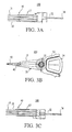
- FIGs. 3A-3C are a left side view, a plan view and a right side view,
respectively, of a detailed structure of an actuator shown in FIG. 1.
- FIGs. 4A and 4B are a plan view and a side view, respectively, of a minutely
moving mechanism shown in FIGs. 3A-3C.
- FIGs. 5A and 5B are a plan view and a side view, respectively, of the
minutely moving mechanism shown in FIGs. 3A-3C.
- FIGs. 6A-6C are a plan view, a side view, and a sectional view, respectively,
for explaining a principle of an increased stroke of the minutely moving mechanism
shown in FIGs. 3A-3C.
- FIGs. 7A and 7B are a plan view and a side view showing a variation of the
minutely moving mechanism shown in FIGs. 5A and 5B.
- FIGs. 8A and 8B are a plan view and a side view showing another variation
of the minutely moving mechanism shown in FIGs. 5A and 5B.
- FIGs. 9A and 9B are a plan view and a side view showing still another
variation of the minutely moving mechanism shown in FIGs. 5A and 5B.
- FIG. 10 is a block diagram for explaining a control system in the hard disc
drive shown in FIG. 1.
- Referring now to accompanying drawings, a description will be given of an
HDD 11 as one embodiment according to the present invention. The HDD 11
includes, in a housing 12 as shown in FIG. 1, one or more magnetic disc(s) 13 as a
date medium or record carrier, a spindle motor 14, and a magnetic head part. Here,
FIG. 1 is a plan view showing an internal structure of the HDD 11.
-
-
The housing can be made, for example, of aluminum die casting or stainless
steel, and has a rectangular parallelepiped shape to which a cover (not shown) is
coupled so as to seal its internal space. Each magnetic disc 13 in this embodiment
has high recording density, such as 100 Gb/in2 or even higher, and is mounted on a
spindle of the spindle motor 14.
-
The spindle motor 14 rotates the magnetic disc 13 at a high speed, such as
7,200 rpm and 10,000 rpm, and includes a brushless DC motor (not shown) and a
spindle as its rotor part. For example, when two magnetic discs 13 are used, a disc, a
spacer, a disc, and a clamp are stacked in this order on the spindle, and fixed by a bolt
engaged with the spindle. Unlike this embodiment, the magnetic disc 13 may be a
disc having a hub without a center hole, and the spindle rotates the disc through the
hub.
-
The magnetic head part includes a slider 19, and an actuator 100 that serves
as a mechanism for positioning and driving the slider 19.
-
The slider 19 includes, as shown in FIG. 2, a slider body 22 having an
approximately rectangular parallelepiped shape made of Al2O3-TiC (altic), and a
head-device built-in film 24 secured at an air outflow end of the slider body 22 and
made of Al2O3 (alumina), the film 24 including a built-in read/write head 23. Here,
FIG. 2 is an enlarged perspective view of the slider 19. The slider body 22 and
head-device built-in film 24 define a floatation surface 25 as a surface opposite to a
carrier, i.e., the magnetic disc 13, which surface 25 catches air current 26 generated
from the rotating magnetic disc 13.
-
A pair of rails 27 are formed on the floatation surface 25, extending from an
air inflow end to the air outflow end. A so-called air-bearing surface (referred to as
"ABS" hereinafter) 28 is defined at a top (i.e., outer) surface of each rail 27. The
buoyancy is generated at the ABS 28 by the air current 26. The head 23 embedded
in the head-device built-in film 24 is exposed at the ABS 28. The floatation system
of the slider 19 is not limited to this form, but may use a known dynamic pressure
lubricating system, a known static pressure lubricating system, a known piezoelectric
control system, and any other known floatation system. Unlike the instant
embodiment, which uses a contact start stop system in which the slider 19 contacts the
disc 13 at the time of stop, the slider 19 may be lifted up over the disc 13 before the
disc 13 stops, held at a holding part (sometimes referred to as a ramp) located outside
the disc 13 so as to hold the slider 19 in a non-contact manner with the disc 13, and
dropped from the holding part over the disc 13 when the disc 13 runs, as in the
dynamic or ramp loading system.
-
The head 23 includes a magnetoresistive/inductive composite head including
an inductive head device for writing binary information into the magnetic disc 13
using a magnetic field induced by a conductive coil pattern (not shown), and a
magnetoresistive ("MR" hereinafter) head device for reading resistance as binary
information changing according to a magnetic field generated by the magnetic disc 13.
The MR head device may use any type, such as a giant magnetoresistive ("GMR")
type including both a Current in Plane ("CIP") structure and a Current Perpendicular
to Plane ("CPP") structure, a tunneling magnetoresistive type ("TMR"), and an
anisotropic magnetoresistive ("AMR") type.
-
Turning back to FIG. 1, the actuator 100 includes a voice coil motor (not
shown in FIG. 1), a support shaft 15, and a carriage 16. FIGs. 3A-3C show details of
an actuator 100: FIGs. 3A-3C are a left side view, a plan view, and a right side view,
respectively, of the actuator 100. As illustrated herein, the actuator 100 drives six
sliders 19 for recording data into and reproducing data from both sides of three discs
13, but the number of discs 13 is not limited to three, as discussed above.
-
The voice coil motor includes a flat coil 34 between two yokes 32 at one side
with respect to the support shaft 15. The flat coil 34 is provided opposite to a
magnetic circuit (not shown) provided in the housing 12 of the HDD 11, and actuator
100 swings in accordance with a current value flowing in the flat coil 34. The
magnetic circuit includes, for example, a permanent magnet fixed onto an iron plate
fixed in the housing 12, and a mobile magnet fixed onto the carriage 16. The support
shaft 15 is inserted into a cylindrical hollow hole in the carriage 16, and arranged such
that it extends perpendicular to the paper surface in FIG. 1 in the housing 12.
-
The carriage 16 includes plural (e.g., four) rigid arms 17 each operable
rotatably or swingably around the support shaft 15, plural (e.g., six) suspensions 18
each of which is attached to a tip of the corresponding arm 17 and extends forward
from the arm 17, and plural (e.g., four) bases 41 each of which connects the
suspension 18 to the arm 17. The base 41 constitutes a fine tracking mechanism 40
which will be described with reference to FIGs. 4A and 4B.
-
One or two suspensions 18 are attached to a tip of each arm 17. The arm 17
has a pectinate shape viewed from a side at one side with respect to the support shaft
15. The suspension 18 can be, for example, a Watlas type suspension made of
stainless steel, which uses a gimbal spring (not shown) to cantilever the slider 19,
The suspension 18 also supports a wiring part 18a connected to the slider 19 through a
lead, etc. The wiring part 18a is depicted in FIGs. 4A, which will be described later.
The sense current, read-in data, and read-out data are supplied and output between the
head 23 and the wiring part 18a through such a lead. The wiring part 18a is
connected to a junction flexible printed circuit ("FPC") board 30.
-
The suspension 18 applies an elastic force to the slider 19 against a surface of
the magnetic disc 13. As described later, the instant embodiment reduces the
attachment tolerance of the suspension 18 to a surface of the arm 17 as compared with
prior art structures, and thus the dispersed elastic force which the suspension 18
applies to the slider 19 is almost always within a permissible designed range. In
addition, as described later, the flatness of each of the suspension 18 and the slider 19
is improved in comparison with the prior art structures, thereby preventing head crash
and lowered positioning accuracy under excessive elastic force and torsion.
-
A description will now be given of the fine tracking mechanism 40 for the
actuator 100, with reference to FIGs. 4A to 5B. Here, FIG. 4A is an enlarged plan
view of the fine tracking mechanism 40 for the actuator 100, and FIG. 4B is a
schematic side view of FIG. 4A. FIG. 5A is an enlarged plan view of the base 41
shown in FIGs. 4A and 4B, and FIG. 5B is a schematic side view of FIG. 5A.
-
The fine tracking mechanism 40 provides a fine adjustment when the head 23
is in an on-track state, as well as a quick seek in cooperation with the voice coil motor
during the seek time. The mechanism 40 for the head 23 or suspension 18 is
provided between each suspension 18 and each arm 17, and provides a mechanism for
moving the suspension 18 independent of swinging of the actuator 100 around the
support shaft 15.
-
The fine adjustment mechanism 40 includes the base 41, two pairs of
piezoelectric elements 42a-42d (which are generalized by reference numeral 42), an
insulating layer 43, a conductive layer 44, a piezoelectric-element coupling plate 45, a
caulking part 46, and a connecting part 47.
-
The base 41 is fixed onto the arm 17 which swings around the support shaft
15, and the suspension 18 which supports the slider 19. The base 41 connects the
suspension 18 to the slider 19. The base 41 is fixed onto the arm 17 via a caulking
part 46. The base 41 has slits 41a-41c, as shown in FIG. 5A in which the
piezoelectric-element coupling plate 45 is removed from FIG. 4A. The slits 41a and
41c are formed in a direction perpendicular to a longitudinal direction L of the base 41,
near a centerline C in the base 41, while the slit 41b forms a T shape symmetrical with
respect to the centerline C. As a result, the slits 41a-41c allow the base 41 to include
a mobile part 41d which secures the suspension 18 and may move minutely with the
suspension 18, a mobile part 41e which mounts piezoelectric elements 42a and 42c at
the side of the mobile part 41d, and a fixed part 41f which is connected to the arm 17
side and mounts the piezoelectric elements 42b and 42d. The mobile parts 41d and
41e are movable relative to the fixed part 41f.
-
In this way, the base 41 of this embodiment has the mobile part 41d that may
finely move the suspension 18, and serves as a conventional hinge plate. When the
hinge plate is inserted between the base 41 and the suspension 18, the attachment
tolerance of the suspension 18 is affected by hinge plate's dimension tolerance, but
the instant embodiment removes the hinge plate between the base 41 and the
suspension 18 and reduces the dispersion of the attachment tolerance of the
suspension 18 in comparison with a structure in which the hinge plate is located
between them. Thereby, as shown in FIG. 3A, the HDD 11 may accommodate plural
discs 13. When the suspension's attachment tolerance exceeds a design value, it
becomes difficult to accommodate a predetermined number of discs 13 in the disc
drive having a predetermined thickness. Therefore, the reduced attachment tolerance
of the suspension would be helpful particularly when the HDD 11 drives a plurality of
discs. In addition, the reduced dispersion in the suspension's attachment tolerance
means that the suspension may be attached with precision closer to a design value.
Therefore, the elastic force, for example, as seen in a contact start stop system where
the suspension 18 applies a preset elastic force to the disc 13, comes close to the
design value, preventing head crash and improving positioning accuracy. Moreover,
the base 41 that serves as a hinge plate contributes to the reduced number of
components, low profile, and cost reduction of the fine positioning mechanism 40.
-
The piezoelectric element 42 is a shear type piezoelectric element that is
polarized in a direction orthogonal to its thickness direction, and deforms its top and
bottom surfaces perpendicular to the thickness direction when voltage is applied to the
piezoelectric element 42 in the thickness direction. The shear type piezoelectric
element shears or sliding deformation when voltage is applied to its top and bottom
surfaces. Therefore, when voltage is applied while one electrode is mounted, for
example, on a bottom surface and the other electrode is mounted, for example, on a
top surface, it deforms in the polarization direction. The piezoelectric element 42 is
provided on the base 41, and deforms the mobile parts 41d and 41e in the base 41
through the slits 41a-41c. A Cu/Ar film is formed through sputtering at the top and
bottom surfaces of the piezoelectric element 42.
-
The piezoelectric element 42 is provided at one surface 41g on the base 41,
while the suspension 18 is provided at another surface 41h on the base 41 opposite to
the surface 41g. When the piezoelectric element 42 is inserted between the base 41
and the suspension 18, the attachment tolerance of the suspension 18 is subject to the
dimension tolerance of the piezoelectric element, but the instant embodiment does not
insert a piezoelectric element between the base 41 and the suspension 18 as in the
prior art structure, reducing the accumulation of attachment tolerance of the
suspension 18 in comparison with a structure that interposes the piezoelectric element.
This structure provides the same effect as the above structure that does not interpose
the piezoelectric element; the instant embodiment enhances the effect by interposing
neither the hinge plate nor the piezoelectric element. As a consequence, the
attachment tolerance of the suspension 18 to the arm 17's surface depends only upon
the thickness tolerance and the flatness of the base 41, and is not affected by
dimensions of the piezoelectric element 42 or any other component (e.g., the
piezoelectric-element coupling plate 45) (which is coupled with a top side shown in
FIG. 4B) of the piezoelectric element 42.
-
Next follows a description of how the stroke is increased by the fine
positioning mechanism 40 with reference to FIG. 6. Here, FIGs. 6A-6C are a plan
view, a schematic side view, and a schematic sectional view, respectively, for
explaining a principle of the increased stroke of the mechanism 40. The arrangement
of slits in FIGs. 6A-6C is the same as that in FIGs. 8A and 8B, but may be the same as
that shown in FIGs. 5A and 5B.
-
As shown in FIG. 6A, four piezoelectric elements 42a-42d are provided on
the base 41: The piezoelectric elements 42a and 42c are provided at a side of the
mobile part 41e, while piezoelectric elements 42b and 42d are provided at a side of
the fixed part 41f. The piezoelectric element 42 may be provided at only one side
(for example, 42a and 42b). Each piezoelectric element 42 may have a different size,
but preferably exhibits a symmetrical deformation with respect to the centerline C.
Therefore, the piezoelectric element at the side of the mobile part 41e and the
piezoelectric element at the side of the fixed part 41f may have different size.
-
Theoretically, the present invention may use an unrestricted number of
piezoelectric elements 42 according to the length of the movement or strokes to be
maintained, but the instant embodiment adopts four piezoelectric elements as a typical
example in the HDD 11. Although the total number of piezoelectric elements 42 is
not limited to four, an even number, such as a multiple of four, is preferable. As
described above, the slits 41a-41c are formed in the base 41 so as to divide the base
41 into the mobile part 41d that is fixed onto the suspension 18 and exhibits swing
actions, the part (or mobile part 41e) that mounts the piezoelectric elements 42a and
42c at the mobile part 41a side and the piezoelectric-element mounting part 41f at the
fixed side. These slits 41a-41c serve to enhance the movement of the piezoelectric
element 42, and move the suspension 18 smoothly.
-
The piezoelectric element 42 has been polarized in an arrow direction in
advance as shown in FIG. 6A: the piezoelectric elements 42a and 42d have been
polarized in a direction L1, while the piezoelectric elements 42b and 42c have been
polarized in a direction L2. The piezoelectric elements 42a and 42b forms a pair,
while the piezoelectric elements 42c and 42d forms a pair. Therefore, the
piezoelectric elements 42 have opposite polarization directions in each pair.
-
Referring now to FIG. 5A, the piezoelectric element 42 is formed, through an
insulating layer 43, on the conductive layer 44 that serves as an electrode for the
piezoelectric element 42. In the instant embodiment, the base 41 is made of stainless
steel. The insulating layer 43 is made of polyimide, and a film with a thickness of 10
µm is formed on the base 41. The conductive layer 44 has a thickness, for example,
of 5 µm. The piezoelectric-element coupling plate 45 also serves as an electrode.
As a result, voltage is applied to the piezoelectric element 42 between the conductive
layer 44 and the piezoelectric-element coupling plate 45. The instant embodiment
thus forms the conductive layer 44 as a direct electrode on the base 41. The
piezoelectric-element coupling plate 45 serves as an electrode, and is made of
stainless steel. The conventional structure interposes an electrode plate between the
base 41 and the suspension 18 in addition to the piezoelectric element, but attachment
tolerance of the suspension 18 is reduced even in the conventional structure where
another member serves as an electrode instead of providing an electrode plate as an
independent member. Although the instant embodiment forms a film of the
insulating layer 43 and conductive layer 44 on the stainless base 41, a member having
the insulating layer 43 and conductive layer 44 may be bonded.
-
The piezoelectric element 42 operates when voltage is applied between the
conductive layer 44 and a pair of piezoelectric-element coupling plate 45. FIG. 6C
shows actions of a pair of piezoelectric elements 42c and 42d: The top in FIG. 6C
shows a state before the voltage is applied, and the bottom in FIG. 6C shows a state
after the voltage is applied. As illustrated, only when the voltage is applied between
the bse 41 and the piezoelectric-element coupling plate 45, the piezoelectric elements
42c and 42d, which have been polarized in reverse directions in advance, shear (or
exhibit sliding deformation) in reverse directions to each other. Thereby, the
deformed amount at the side of the mobile part 41e becomes doubled by the deformed
amount 2d in comparison with the deformed amount d of one piezoelectric element.
Therefore, the instant embodiment may enlarge the stroke without increasing the
thickness of the mechanism 40.
-
In other words, as the bottom surface of the piezoelectric element 42d is fixed
onto the fixed part 41f in FIG. 6C, the top surface of the piezoelectric element 42d
deforms by d. The deformed amount d moves the piezoelectric-element coupling
plate 45 to the left side, consequently deforming the piezoelectric element 42c and the
mobile part 41e. In addition, the piezoelectric element 42c itself deforms with the
mobile part 41e to the left side by the deformed amount d due to its own deformation.
At this time, since the top surface of the piezoelectric element 42c is fixed by the
piezoelectric-element coupling plate 45 in the right direction, the bottom surface of
the piezoelectric element 42c moves with the mobile part 41e to the left side. In this
way, the piezoelectric-element coupling plate 45 serves to transmit the deformation of
the piezoelectric element 42 at the fixed part 41f side to the mobile part 41e side, as
well as fixing the top surface of the piezoelectric elements 42c and 42d in the same
manner.
-
The piezoelectric-element coupling plate 45 has an approximately rectangular
shape, and partially exposes the piezoelectric elements 42b and 42d in FIG. 4. The
piezoelectric elements 42b and 42d are wire-bonded to each other through a wire 49,
and the piezoelectric element 42d is connected to the terminal 47a on the connection
part 47. The exposed part of the piezoelectric element 42 is covered with an Au film
that facilitates wire bonding, and the wire bonding becomes easier as the thickness
increases. The wire is coated with resin so as not to be vibrated and damaged by
wind or any other exiting force in the HDD 11. The terminal 47a is connected to a
wiring pattern that drives the arm 17 around the support shaft 15. The current
applied to the piezoelectric elements 42d and 42b through the wire bonding is
supplied to the piezoelectric elements 42a and 42c via the piezoelectric-element
coupling plate 45. Thereby, the wiring pattern may control minute driving of the
suspension 18 as well as the driving of the arm 17. The wiring pattern is formed, for
example, in the control part 71 in a control system 70, which will be described later.
-
FIGs. 7A and 7B show a mechanism 40A as a variation of the mechanism 40
shown in FIGs. 5A and 5B. Here, FIG. 7A is a schematic plan view showing the
mechanism 40A near the base 41, and FIG. 7B is a schematic sectional view of FIG.
7A. The mechanism 40A has the base 41. piezoelectric element 42, and
piezoelectric-element coupling plate 45 (not shown), but is different from the
mechanism 40 in that it does not have the insulating layer 43 and the conductive layer
44. The piezoelectric element 42 is bonded to the base 41, and the base 41 is kept
electrically grounded. Therefore, a desired voltage may be applied to the
piezoelectric-element coupling plate 45 in the mechanism 40A. The mechanism 40A
does not require a formation of the insulating and conductive layers, facilitating
manufacture and cost reduction.
-
FIGs. 8A and 8B show a mechanism 40B as a variation of the mechanism 40
shown in FIGs. 5A and 5B, Here, FIG. 8A is a schematic plan view showing the
mechanism 40B near the base 41, and FIG. 8B is a schematic sectional view of FIG.
8A. The mechanism 40B has the slits 41a and 41c of FIG.5A, but is different from
the mechanism 40 in that it does not have the slit 41b. In this way, shapes and
arrangement of the slits are not limited to those shown in FIGs. 5A and 5B. The slits
among the piezoelectric elements 42 attempt to integrally form the base 41 and the
part 41d to be fixed onto the suspension 18, and thus are designed to have proper
shapes so as not to prevent relative movement of the piezoelectric elements 42.
-
FIGs. 9A and 9B show a mechanism 40C as a variation of the mechanism 40
shown in FIGs. 5A and 5B. Here, FIG. 9A is a schematic plan view showing the
mechanism 40C near the base 41, and FIG. 9B is a schematic sectional view of FIG.
9A. The mechanism 40C is different from the mechanism 40 in that it has the
piezoelectric-element coupling plate 45A coupled by flexible part 45a instead of the
piezoelectric-element coupling plate 45. The piezoelectric-element coupling plate
45A is a partially notched shape from a rectangle such that only the piezoelectric
element 42d is partially exposed, and the piezoelectric elements 42d is wire-bonded to
a terminal 47a on the connection part 47. Thus, such a connected
piezoelectric-element coupling plate 45 reduces the number of wire bondings in
comparison with the structure shown in FIGs. 5A and 5B. Since each pair of
piezoelectric elements 42 relatively deform, the wire bonding preferably has
sufficiently low rigidity so as no to restrain their deformations. In addition, it is
easier to manufacture the structure shown in FIGs. 9A and 9B than to manufacture the
wire bonding structure shown in FIGs. 5A and 5B.
-
FIG. 10 shows a control block diagram of a control system 70 in the HDD 11.
The control system 70, which may be implemented as a control board, etc. in the HDD
11, includes a control part 71, an interface 72, a hard disc controller (referred to as
"HDC" hereinafter) 73, a write modulation part 74, a read demodulation part 75, a
sense-current control part 76, and a head IC 77. Of course, they are not necessarily
arranged as one member; for example, only the head IC 77 is connected to the
carriage 16.
-
The control part 71 covers any processor such as a CPU and MPU
irrespective of its name, and controls each part in the control system 70. The
interface 72 connects the HDD 11 to an external apparatus, such as a personal
computer ("PC" hereinafter) as a host. The HDC 73 sends to the control part 71 data
that has been demodulated by the read demodulation part 75, sends data to the write
modulation part 74, and sends to the sense-current control part 76 a current value as
set by the control part 71. Although FIG. 10 shows that the control part 71 achieves
servo control over the spindle motor 14 and (a motor in) the actuator 100, the HDC 73
may serve as such servo control.
-
The write modulation part 74 modulates data and supplies data to the head IC
77, which data has been supplied from the host through the interface 72 and is to be
written down onto the disc 13 by an inductive head 50. The read demodulation part
75 demodulates data into an original signal by sampling data read from the disc 13 by
the MR head device 51. The write modulation part 74 and read demodulation part 75
may be recognized as one signal processing part. The head IC 77 serves as a
preamplifier. Each part may apply any structure known in the art, and a detailed
description thereof will be omitted.
-
In operation of the HDD 11, the control part 71 drives the spindle motor 14
and rotates the disc 13. The airflow associated with the rotation of the disc 13 is
introduced between the disc 13 and slider 19, forming a minute air film and thus
generating the buoyancy that enables the slider 19 to float over the disc surface. The
suspension applies the elastic pressure onto the slider 19 in a direction against the
buoyancy of the slider 19. The balance between the buoyancy and the elastic force
spaces the slider 19 from the disc 13 by a constant distance. As discussed above, the
elastic pressure applied by the suspension 18 is closed to the designed value,
preventing crashing.
-
The control part 71 then controls the actuator 100 and rotates the carriage 16
around the support shaft 15 and makes the fine positioning mechanism 40 swing for
head 23's seek for a target track on the disc 13. The instant embodiment thus uses a
swing arm type in which the slider 19 draws an arc locus around the support shaft 15,
but the present invention is applicable to a linear type in which the slider 19 is a linear
locus.
-
Initially, the control part 71 controls driving of the arm 17 around the support
shaft 15 to perform a rough seek. Next, the control part 71 performs a fine seek so as
to correct overshoot resulting from the rough seek by controlling voltage applied to
the piezoelectric element 42 in the mechanism 40. The large stroke in the
mechanism 40 is effective to save time necessary for settling and quicken the settling
at the time of seek. In addition, the large stroke presents high resistance to
disturbance, such as external vibrations. If necessary, unlike the instant embodiment
that doubles the stroke, the stroke may be made 1.5 times as large to save power.
-
When voltage corresponding to the deformed amount that has been
determined by the control part 71 is applied to the terminal 47a in the connection part
47, the mechanism 40 in FIGs. 5A and 5B uses wire bonding to apply the voltage to
the piezoelectric elements 42d and 42b. On the other hand, the mechanism 40C in
FIGs. 9A and 9B uses wire bonding to apply the voltage to the piezoelectric element
42d and then to the piezoelectric elements 42a-42c through the piezoelectric-element
coupling plate 45.
-
When the voltage is applied to the piezoelectric element 42, the piezoelectric
elements 42a and 42b deform such that they are separated from each other while the
piezoelectric elements 42c and 42d deform such that they approach each other, as
shown in FIG. 6A. As a result, in FIGs. 5A and 5B, the mobile part 41e deforms and
then the mobile part 41f deforms. Thereby the suspension 18 minutely moves and
positions the slider 19 at a desired track.
-
Although the arm 17 must be moved for movement outside the stroke range
of the mechanism 40, the mechanism 40 of the instant embodiment has a more
increased stroke than conventional structures and thus is advantageous for quick
positioning because of the reduced number of moving times of the arm 17. In
addition, as described above, the mechanism 40 exhibits high positioning accuracy,
since the suspension 18 does not become inclined when the piezoelectric-element
coupling plate 45 inclines relative to the surface 41g on the base 41.
-
In a write time, the control part 71 receives data from the host such as a PC
(not shown) through the interface 72. selects the inductive head device, and sends data
to the write modulation part 74 through the HDC 73. In response, the write
modulation part 74 modulates the data, and sends the modulated data to the head IC
77. The head IC 77 amplifies the modulated data, and then supplies the data as write
current to the inductive head device. Thereby, the inductive head device writes down
the data onto the target track.
-
In a read time, the control part 71 selects the MR head device, and sends the
predetermined sense current to the sense-current control part 76 through the HDC 73.
In response; the sense-current control part 76 supplies the sense current to the MR
head device through the head IC 77. Thereby, the MR head reads desired data from
the desired track on the disc 13. Data is amplified by the head IC 77 based on the
electric resistance of the MR head device varying according to a signal magnetic field,
and is then supplied to the read demodulation part 75 to be demodulated to an original
signal. The demodulated signal is sent to the host (not shown) through the HDC 73,
controller 71, and interface 72.
-
Further, the present invention is not limited to these preferred embodiments,
and various modifications and changes may be made in the present invention without
departing from the spirit and scope thereof. Although the instant embodiments refer
to a HDD, the present invention is applicable to any type of disc drive (such as an
optical disc drive).
-
One aspect of the present invention reduces the number of components
between the base and suspension, and may provide the head moving mechanism in
which the suspension's attachment tolerance does not vary so widely. As a result,
the elastic force which the suspension applies to the disc becomes close to the
designed value, preventing crash and lowered positioning accuracy. Another aspect
of the present invention may provide a head moving mechanism having a double
stroke. This structure consequently provides quick positioning and fast settling
without swinging the arm. The large stroke presents high resistance to disturbance,
such as external vibrations, because the large stroke allows the mechanism to cancel
large forces placed on the head by such disturbances.