EP1331165A2 - Befestigungseinrichtung für ein Fahrradschutzblech - Google Patents
Befestigungseinrichtung für ein Fahrradschutzblech Download PDFInfo
- Publication number
- EP1331165A2 EP1331165A2 EP03009142A EP03009142A EP1331165A2 EP 1331165 A2 EP1331165 A2 EP 1331165A2 EP 03009142 A EP03009142 A EP 03009142A EP 03009142 A EP03009142 A EP 03009142A EP 1331165 A2 EP1331165 A2 EP 1331165A2
- Authority
- EP
- European Patent Office
- Prior art keywords
- mudguard
- fixing
- rod
- groove
- boss
- Prior art date
- Legal status (The legal status is an assumption and is not a legal conclusion. Google has not performed a legal analysis and makes no representation as to the accuracy of the status listed.)
- Granted
Links
Images


Classifications
-
- B—PERFORMING OPERATIONS; TRANSPORTING
- B62—LAND VEHICLES FOR TRAVELLING OTHERWISE THAN ON RAILS
- B62J—CYCLE SADDLES OR SEATS; AUXILIARY DEVICES OR ACCESSORIES SPECIALLY ADAPTED TO CYCLES AND NOT OTHERWISE PROVIDED FOR, e.g. ARTICLE CARRIERS OR CYCLE PROTECTORS
- B62J15/00—Mud-guards for wheels
- B62J15/02—Fastening means; Stays
Definitions
- the present invention relates to a device for fixing of a bicycle mudguard with radial rods starting from the hub of the wheel.
- a device of this kind is for example described in the patent European EP 0 742 137. It comprises a body made of plastic material comprising a pair of parallel holes for the passage of two rods, a groove intended to accommodate the longitudinal edge of the mudguard and a hole, essentially perpendicular to the holes of said pair, opening into the interior of said groove and allowing by means of a screw self-tapping to fix both said device on the rods and fix the mudguard.
- Document DE 29614001 discloses a device for fixing bicycle mudguard comprising means for fixing the device to a rod and means for fixing the mudguard comprising a fixing screw securing this device and the mudguard, and a groove into which the longitudinal edge of the mudguard is inserted.
- This groove has a retaining bottom of shape complementary to a bead formed in the longitudinal edge of the mudguard.
- the present invention aims to provide a device of this type which, compared to the devices of the prior art, is less expensive to make and allow to install the mudguard on the device easily, especially without tools.
- the fixing device according to the invention can thus be manufactured in one piece, with means for fixing the mudguard to the rod which are an integral part of the device, which makes it possible to fix the mudguard without tools.
- the means of prevention of the longitudinal movement of the mudguard in the groove include the stop of the device against the lateral edges of a boss formed in protruding outwards into the mudguard.
- the means of prevention of the longitudinal movement of the mudguard in the groove include a housing in which is adapted to be inserted a boss formed in protruding inwards into the mudguard.
- the means of prevention of the longitudinal movement of the mudguard in the groove include a wall formed in the groove cooperating with a shaped notch complementary formed transversely in the longitudinal edge of the fender.
- the fixing device according to the invention can also be characterized by an elongated body and at least one fixing lug having a zone of connection with the external face of said body and making protrudes so as to define between it and the outer surface of the body the means for fixing the longitudinal edge of the mudguard.
- this fixing lug is preferably adapted to be inserted in the protrusion on the outside of the mudguard, the edges lateral of said fixing lug being adapted to cooperate with the lateral edges of said boss.
- the device is preferably made of synthetic material, especially by molding.
- It can take the form of an elongated body with one or more fixing lugs connected to the elongated body and curved towards said body, forming between them and said body the retaining groove of the bead of the mudguard.
- Retention of the longitudinal flange of the mudguard in the groove may also include an upper tab located above the fixing lugs and the underside of which is suitable for contacting the outer wall of the mudguard.
- the device consists of two half-shells which are assembled and fixed together by enclosing the rod.
- the device is provided with stop means preventing movement of the mudguard in its longitudinal direction.
- These means include for example the stop of the device against the lateral edges of a boss projecting outwards in the fender.
- They can also consist of a housing in which is adapted to be inserted a boss projecting inwardly into the fender.
- the means of fixing the device to the rod have an opening opening perpendicularly into a passage for the rod and rod locking means introduced in said opening and cooperating with the rod.
- These blocking means for example consist of a plug having two locking tabs adapted to be inserted on either side of the rod, the inner face said legs having grooves adapted to cooperate with complementary grooves on the outer surface of the rod in a direction perpendicular to the general axis of the rod.
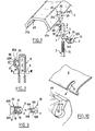
- the fixing device 1 is intended to fix a mudguard 2 to a rod 3 starting from the bicycle wheel hub (not shown).
- Two devices fixing 1 are used to fix the two longitudinal edges 4A and 4B of the mudguard 2.
- the fixing device 1 comprises an elongated body 5 in which a passage 6 is provided for the rod 3 and closed by a bottom 7.
- a passage 6 is provided for the rod 3 and closed by a bottom 7.
- an opening 9 is provided in the body 5 opening perpendicularly into the cooperating passage 6 with a plug 10 having a head 11 and two locking tabs 12A, 12B extending in parallel planes.
- the facing faces one of the other of the locking tabs 12A, 12B are provided with grooves 13 parallels extending in a direction perpendicular to the leading edge respective 14A, 14B of each of the legs 12A, 12B.
- On the rod 3 striations 15 are also provided in planes perpendicular to the axis of the rod 3 and on two diametrically opposite lateral zones.
- the diameter of the passage 6 in the body 5 is such that, once the rod 3 inserted, the plug 10 can be inserted through the opening 9 so that its two locking tabs 12A, 12B, frame the rod 3, the streaks 13 of the plug 10 and the streaks 15 of the interlocking rod to block the device 1 on the rod.
- the height of the streaks 15 on the lateral zones of the rod is such that an adjustment of the device is possible depending on the bicycle to be equipped.
- a fixing lug 20 is protruding opposite the opening 9.
- the width of the tab 20 is substantially equal to the width or diameter of the body 5.
- the tab 20 comprises a zone of connection 21 with the body 5 of the device above the recess 18.
- the fixing lug 20 extends generally in direction of the upper end 22 of the body 5 away from the wall outer 24 of the body 5 so that a groove 25 is defined between this fixing lug 20 and said wall 24.
- a portion end 26 of tab 20 is curved towards the elongated body 5 so that the groove 25 has a shape complementary to a bead 27A, 27B ending respectively in the longitudinal edge 4A, 4B of the mudguard and so that the groove is provided with a bottom widened 30.
- the device 1 as well as the plug 10 and a cord 32 connecting the body plug 5 are made in one piece by molding a synthetic material. This material allows a certain flexibility of the fixing lug 20 around its connection zone and allows the bead from the edge of the mudguard to be inserted into the widened bottom 30 of the groove 25, the tab 20 then returning to its rest position.
- stop means are also provided to prevent longitudinal movement of the mudguard. They include a boss 35 protruding from the outside of the mudguard in the extension of the longitudinal edge 4A, 4B of the mudguard.
- the boss 35 has a projecting edge 36, two lateral edges 37A and 37B and a front edge 38 which extends to the longitudinal edge 4A, 4B.
- the fixing lug 20 is adapted to be introduced into the boss 35, so that the abutment of its lateral edges 40A, 40B against the face inner side edges 37A, 37B of the boss, prevents the longitudinal movement of the mudguard.
- FIGS. 5 to 7 another example of embodiment in which the device consists of rear half-shells 41 and before 42 which enclose the rod, each comprising this effect a semicircular section groove over its entire height, the two half-shells being assembled and fixed to the rod using a clamping screw (not shown) inserted in two threaded holes 43A, 43B arranged perpendicularly and in the extension one of the other in the two half-shells.
- the lower end of the half-shells is shaped like a point.
- the retaining groove, referenced 45 here, the bead 27A, 27B, the mudguard is formed in the half-shell before 42 which for this purpose has a greater thickness than the rear half-shell 43.
- the groove 45 has an enlarged bottom 46 of complementary shape to the bead 27A, 27B and an inclined portion 48 in which is located the edge of the mudguard behind the bead. As seen in Figure 6, to achieve the stop means preventing the longitudinal movement of the mudguard, the groove 45 has an enlarged area on the side of passage 47 of the rod, centered with respect thereto, and forming a housing 49 in which the boss 35 projecting from the outside of the mudguard is intended to be introduced.
- the housing 49 has a rear wall 49a intended to come in contact with the right front edge 37B of the boss 35 and a wall upper inclined 49b connecting the rear wall 49a to the inlet 49c of the groove 45 and side walls 50A, 50B (see Figure 7), the edges lateral 37A, 37B of the boss abutting against these walls side.
- Figures 8 and 9 show, compared to the example of Figures 5 to 7, a first alternative embodiment of the stop means in which, a boss 55 is this time protruding towards the inside of the mudguard, cooperating with a cylindrical housing 56 formed in the front half-shell 42 in the direction of the front wall 42a thereof and opening into the retaining groove 45 of the mudguard.
- FIG. 10 shows a second alternative embodiment of the stop means comprising a wall 60 formed perpendicularly in the bottom of the groove 45 away from the ends of the groove introduced into a notch 61 formed transversely in the edge of the mudguard 2.
- FIGS. 11 to 14 illustrate a third embodiment of the invention.
- This example has points in common with the first example shown in FIGS. 1 to 4, with regard to the body 5 (to the exception of the step 18 which is not reproduced here) and the means for fixing the device to the rod, which will therefore not be described here.
- the device according to this example is characterized by the presence of two fixing lugs 70a and 70b, having, as can be seen better on the Figure 12, connection areas 71a, 71b respectively, to the body 5 of the device located laterally, the legs thus framing the body 5 extending towards the front of it. More precisely here and as we seen in FIG.
- the legs comprise a first portion 72a, 72b allowing them to move away from the body 5 and towards the front thereof, then a second portion 73a, 73b in which the means for fixing the mudguard, said second portions of each leg extending generally in parallel planes. As one can see sideways in FIGS.
- the second portion 73a, 73b comprises a part 74a, 74b bent upwards from the body 5 forming, with the front wall of the body 5, the bottom respectively 75a, 75b of a groove 76a, 76b, adapted to cooperate with the longitudinal bead 27A, 27B of the mudguard and an end portion 77a, 77b curved outward of the device so as to form an upper surface 78a, 78b adapted to come into contact with the inner face of the mudguard.
- an upper tab 80 located between the fixing lugs 70a and 70b and having an area of connection 81 to the body 5 located above the plane containing the connection zones 71a, 71b of said fixing lugs.
- This paw upper 80 has a lower face 82 extending in a plane parallel to that containing the upper face 78a, 78b of the part end of the fixing lugs and adapted to come into contact with the outer surface of the mudguard wall.
- Stop means preventing the longitudinal movement of the mudguard are here consisting of a wall 79a, 79b disposed in each groove 76a, 76b each cooperating with a notch provided for this purpose transversely in the longitudinal edge of the mudguard, as is the case in the variant shown in Figure 10.
- the fixing device according to the invention 150 includes, as part of the rod attachment means, in the part of the rod clamp provided for covering the rod, two tightening wings 155, 156 defining a rod passage 160 substantially conical with a threaded conical outer surface 154 cooperating with a nut tapered 151 tapped in its inner surface 153.
- This method of fixing of the rod to the device according to the invention is particularly effective because the tightening of the conical nut guarantees a locking of the position relative of the rod in the rod passage.
- positioning means could be provided rod of this type, for example one or more partitions connected perpendicular to the wall of the body and having an oblong hole for the passage of the rod.
- the device could also include a second passage of rod.
- the device can be made lighter and / or improved elasticity, for example of the upper fixing lug, removing from the material in the parts where the thickness allows it.
Landscapes
- Engineering & Computer Science (AREA)
- Mechanical Engineering (AREA)
- Body Structure For Vehicles (AREA)
- Axle Suspensions And Sidecars For Cycles (AREA)
- Fittings On The Vehicle Exterior For Carrying Loads, And Devices For Holding Or Mounting Articles (AREA)
Applications Claiming Priority (3)
| Application Number | Priority Date | Filing Date | Title |
|---|---|---|---|
| FR9903251A FR2791030B1 (fr) | 1999-03-16 | 1999-03-16 | Dispositif de fixation de garde-boue de velo |
| FR9903251 | 1999-03-16 | ||
| EP00400734A EP1036731B1 (de) | 1999-03-16 | 2000-03-16 | Befestigungsanordnung für Fahrradschutzblech |
Related Parent Applications (1)
| Application Number | Title | Priority Date | Filing Date |
|---|---|---|---|
| EP00400734A Division EP1036731B1 (de) | 1999-03-16 | 2000-03-16 | Befestigungsanordnung für Fahrradschutzblech |
Publications (3)
| Publication Number | Publication Date |
|---|---|
| EP1331165A2 true EP1331165A2 (de) | 2003-07-30 |
| EP1331165A3 EP1331165A3 (de) | 2004-12-15 |
| EP1331165B1 EP1331165B1 (de) | 2006-11-02 |
Family
ID=9543262
Family Applications (2)
| Application Number | Title | Priority Date | Filing Date |
|---|---|---|---|
| EP03009142A Expired - Lifetime EP1331165B1 (de) | 1999-03-16 | 2000-03-16 | Befestigungseinrichtung für ein Fahrradschutzblech |
| EP00400734A Expired - Lifetime EP1036731B1 (de) | 1999-03-16 | 2000-03-16 | Befestigungsanordnung für Fahrradschutzblech |
Family Applications After (1)
| Application Number | Title | Priority Date | Filing Date |
|---|---|---|---|
| EP00400734A Expired - Lifetime EP1036731B1 (de) | 1999-03-16 | 2000-03-16 | Befestigungsanordnung für Fahrradschutzblech |
Country Status (4)
| Country | Link |
|---|---|
| EP (2) | EP1331165B1 (de) |
| AT (1) | ATE259322T1 (de) |
| DE (2) | DE60008155T2 (de) |
| FR (1) | FR2791030B1 (de) |
Cited By (1)
| Publication number | Priority date | Publication date | Assignee | Title |
|---|---|---|---|---|
| EP1884456A1 (de) | 2006-07-28 | 2008-02-06 | Orion-Italy Componenti Biciclette Srl | Vorrichtung zum Befestigen von Fahrradschutzblechen am oberen Ende eines Auflagewinkelstabs |
Families Citing this family (16)
| Publication number | Priority date | Publication date | Assignee | Title |
|---|---|---|---|---|
| DE20008005U1 (de) * | 2000-05-05 | 2000-07-20 | Sks Metaplast Scheffer Klute | Befestigungseinrichtung für einen Radschützer |
| EP1221407A1 (de) * | 2001-01-03 | 2002-07-10 | Kuei C. Huang | Sicherheits-Rasteinrichtung für Fahrradschutzbleche |
| FR2821330A1 (fr) * | 2001-02-28 | 2002-08-30 | Zefal | Piece de raccord pour un accessoire de velo, notamment un garde-boue |
| ITVR20010099A1 (it) * | 2001-09-13 | 2003-03-13 | San Giorgio Bicycle Components | Dispositivo di bloccaggio di un parafango per biciclette costituito da due elementi interconnessi. |
| GB2383314B (en) * | 2001-12-18 | 2005-02-16 | Spencer Mfg Ltd | Connecting device |
| DE20300726U1 (de) | 2003-01-17 | 2003-03-20 | Sks Metaplast Scheffer Klute | Einrichtung zur Befestigung von Streben zur Halterung eines Radschützers am Rahmen eines Zweirades |
| NL1022857C2 (nl) * | 2003-03-06 | 2004-09-09 | Lepper Beheer B V | Koppeling, systeem en fiets. |
| ITVI20030082A1 (it) * | 2003-04-16 | 2004-10-17 | Rpz Di Golin Maria | Dispositivo a graffa per l'assemblaggio di un parafango |
| ITVI20060021A1 (it) | 2006-01-19 | 2007-07-20 | Ivan Passuello | Organo di sgancio di sicurezza, particolarmente per asta unica e parafango |
| EP1944225A3 (de) * | 2007-01-12 | 2009-11-04 | sks-metaplast SCHEFFER-KLUTE GMBH | Befestigungsanordnung für Radschützer und Schutzkappe |
| IT1400657B1 (it) * | 2010-07-05 | 2013-06-28 | Roto Societa A Responsabilita Limitata | Organo di bloccaggio e sostegno, particolarmente per parafanghi di biciclette e simili, e rispettivo parafango. |
| GB2492842A (en) * | 2011-07-14 | 2013-01-16 | Young Operations Ltd H | Bicycle mudguard assembly |
| FR3011807B1 (fr) * | 2013-10-14 | 2017-05-12 | Decathlon Sa | Garde-boue a tete articulee |
| FR3011806B1 (fr) * | 2013-10-14 | 2017-04-14 | Decathlon Sa | Garde-boue a tringle reglable |
| TWI673193B (zh) * | 2018-07-06 | 2019-10-01 | 瑞振工業股份有限公司 | 扣組式土除支撐架 |
| TWI749952B (zh) * | 2020-12-17 | 2021-12-11 | 瑞振工業股份有限公司 | 土除固定裝置 |
Citations (2)
| Publication number | Priority date | Publication date | Assignee | Title |
|---|---|---|---|---|
| DE29614001U1 (de) | 1996-08-13 | 1996-09-26 | Sks Metaplast Scheffer Klute | Vorrichtung zur Befestigung einer Strebe an einem Radschützer |
| EP0742137A2 (de) | 1995-05-11 | 1996-11-13 | ZINCATURA SAN GIORGIO s.n.c. di DE POLI GAVINO & C. | Befestigungsvorrichtung für ein Fahrradschutzblech |
Family Cites Families (4)
| Publication number | Priority date | Publication date | Assignee | Title |
|---|---|---|---|---|
| GB190224477A (en) * | 1902-11-08 | 1903-10-22 | Henry Sidebottom | Improvements in Means for Coupling Metallic Cords, Cables and the like |
| GB303989A (en) * | 1927-12-07 | 1929-01-17 | William Albert Gorton | Improvements in stays of cycle mudguards, luggage carriers, and the like |
| GB2278323A (en) * | 1993-05-25 | 1994-11-30 | Webb Ronald R | Fixing stays to mudguards |
| IT245373Y1 (it) * | 1998-06-24 | 2002-03-20 | San Giorgio Snc Di De Poli Liv | Dispositivo di bloccaggio di un parafango per biciclette |
-
1999
- 1999-03-16 FR FR9903251A patent/FR2791030B1/fr not_active Expired - Fee Related
-
2000
- 2000-03-16 DE DE60008155T patent/DE60008155T2/de not_active Expired - Fee Related
- 2000-03-16 AT AT00400734T patent/ATE259322T1/de not_active IP Right Cessation
- 2000-03-16 EP EP03009142A patent/EP1331165B1/de not_active Expired - Lifetime
- 2000-03-16 EP EP00400734A patent/EP1036731B1/de not_active Expired - Lifetime
- 2000-03-16 DE DE60031728T patent/DE60031728T2/de not_active Expired - Fee Related
Patent Citations (2)
| Publication number | Priority date | Publication date | Assignee | Title |
|---|---|---|---|---|
| EP0742137A2 (de) | 1995-05-11 | 1996-11-13 | ZINCATURA SAN GIORGIO s.n.c. di DE POLI GAVINO & C. | Befestigungsvorrichtung für ein Fahrradschutzblech |
| DE29614001U1 (de) | 1996-08-13 | 1996-09-26 | Sks Metaplast Scheffer Klute | Vorrichtung zur Befestigung einer Strebe an einem Radschützer |
Cited By (1)
| Publication number | Priority date | Publication date | Assignee | Title |
|---|---|---|---|---|
| EP1884456A1 (de) | 2006-07-28 | 2008-02-06 | Orion-Italy Componenti Biciclette Srl | Vorrichtung zum Befestigen von Fahrradschutzblechen am oberen Ende eines Auflagewinkelstabs |
Also Published As
| Publication number | Publication date |
|---|---|
| DE60031728D1 (de) | 2006-12-14 |
| EP1331165A3 (de) | 2004-12-15 |
| DE60031728T2 (de) | 2007-05-31 |
| EP1036731A1 (de) | 2000-09-20 |
| DE60008155D1 (de) | 2004-03-18 |
| EP1331165B1 (de) | 2006-11-02 |
| DE60008155T2 (de) | 2004-09-16 |
| FR2791030A1 (fr) | 2000-09-22 |
| FR2791030B1 (fr) | 2001-06-01 |
| ATE259322T1 (de) | 2004-02-15 |
| EP1036731B1 (de) | 2004-02-11 |
Similar Documents
| Publication | Publication Date | Title |
|---|---|---|
| EP1036731B1 (de) | Befestigungsanordnung für Fahrradschutzblech | |
| EP0327440B1 (de) | Verbindung zwischen einem Wärmeaustauscher und einem Rohrende | |
| FR2473151A1 (fr) | Dispositif de raccordement de tuyaux | |
| FR2825527A1 (fr) | Accessoire d'angle pour goulotte | |
| FR2735960A1 (fr) | Perfectionnements aux bandes de tirage pour le maintien d'une coiffe de coussin | |
| EP3670988A1 (de) | Spannvorrichtung, die einen riemen und einen dichtungsring umfasst | |
| FR2761422A1 (fr) | Dispositif de fixation d'un element quelconque, tel qu'une poignee, sur une paroi | |
| EP0683327B1 (de) | Befestigungselement für Kabel, Rohre oder dergleichen | |
| EP0742329B1 (de) | Verriegelungsvorrichtung für Kraftwagenflügel mit verbesserten Einbaumitteln für Verkleidungskappe | |
| EP0497636B1 (de) | Befestigungseinrichtung einer Stossstange eines Fahrzeuges | |
| EP0742137A2 (de) | Befestigungsvorrichtung für ein Fahrradschutzblech | |
| FR2579026A2 (fr) | Dispositif de raccord pour une embase d'antenne destinee a etre fixee sur une paroi et capuchon d'antiparasitage pour un tel dispositif | |
| FR2786540A1 (fr) | Dispositif de montage pour accessoire a rapporter sur un quelconque article, et baladeuse mettant en oeuvre un tel dispositif de montage | |
| FR2766864A1 (fr) | Dispositif de condamnation d'un ouvrant de vehicule automobile | |
| FR2696917A1 (fr) | Perfectionnement pour siège. | |
| FR2629878A1 (fr) | Dispositif de fixation | |
| EP0991155A1 (de) | Gehäuse, insbesondere für elektrische Geräte, dessen Rückwand mit mindestens einem, mit einer Kappe abgedeckten, Loch versehen ist | |
| EP0911575B1 (de) | Beleuchtungs- oder Signalvorrichtung mit einem Stecker zum Anschluss an ein Fahrzeug | |
| FR2708242A1 (fr) | Dispositif d'essuie-glace à articulation d'éléments. | |
| WO2002022435A1 (fr) | Pret-a-monter de fixation d'un porte-bidon | |
| FR2787554A1 (fr) | Element de fixation intermediaire d'un reflecteur sur une partie d'appui d'un projecteur de vehicule automobile, et projecteur comprenant un tel element | |
| WO2022200702A1 (fr) | Peau de pare-chocs de véhicule automobile | |
| FR2536128A1 (fr) | Agrafe elastique pour fixer un panneau sur un support | |
| FR2799149A1 (fr) | Outil avec moyen de fixation pour un manche | |
| FR2836188A1 (fr) | Agencement pour la fixation d'un troncon d'extremite d'une poignee ou d'un garde-corps tubulaire |
Legal Events
| Date | Code | Title | Description |
|---|---|---|---|
| PUAI | Public reference made under article 153(3) epc to a published international application that has entered the european phase |
Free format text: ORIGINAL CODE: 0009012 |
|
| AC | Divisional application: reference to earlier application |
Ref document number: 1036731 Country of ref document: EP Kind code of ref document: P |
|
| AK | Designated contracting states |
Designated state(s): AT BE CH CY DE DK ES FI FR GB GR IE IT LI LU MC NL PT SE |
|
| PUAL | Search report despatched |
Free format text: ORIGINAL CODE: 0009013 |
|
| AK | Designated contracting states |
Kind code of ref document: A3 Designated state(s): AT BE CH CY DE DK ES FI FR GB GR IE IT LI LU MC NL PT SE |
|
| RAP1 | Party data changed (applicant data changed or rights of an application transferred) |
Owner name: ZEFAL |
|
| 17P | Request for examination filed |
Effective date: 20050608 |
|
| AKX | Designation fees paid |
Designated state(s): DE FR NL |
|
| GRAP | Despatch of communication of intention to grant a patent |
Free format text: ORIGINAL CODE: EPIDOSNIGR1 |
|
| GRAS | Grant fee paid |
Free format text: ORIGINAL CODE: EPIDOSNIGR3 |
|
| GRAA | (expected) grant |
Free format text: ORIGINAL CODE: 0009210 |
|
| AC | Divisional application: reference to earlier application |
Ref document number: 1036731 Country of ref document: EP Kind code of ref document: P |
|
| AK | Designated contracting states |
Kind code of ref document: B1 Designated state(s): DE FR NL |
|
| REF | Corresponds to: |
Ref document number: 60031728 Country of ref document: DE Date of ref document: 20061214 Kind code of ref document: P |
|
| PLBE | No opposition filed within time limit |
Free format text: ORIGINAL CODE: 0009261 |
|
| STAA | Information on the status of an ep patent application or granted ep patent |
Free format text: STATUS: NO OPPOSITION FILED WITHIN TIME LIMIT |
|
| 26N | No opposition filed |
Effective date: 20070803 |
|
| PGFP | Annual fee paid to national office [announced via postgrant information from national office to epo] |
Ref country code: NL Payment date: 20080331 Year of fee payment: 9 |
|
| PGFP | Annual fee paid to national office [announced via postgrant information from national office to epo] |
Ref country code: DE Payment date: 20080325 Year of fee payment: 9 |
|
| PGFP | Annual fee paid to national office [announced via postgrant information from national office to epo] |
Ref country code: FR Payment date: 20080325 Year of fee payment: 9 |
|
| NLV4 | Nl: lapsed or anulled due to non-payment of the annual fee |
Effective date: 20091001 |
|
| REG | Reference to a national code |
Ref country code: FR Ref legal event code: ST Effective date: 20091130 |
|
| PG25 | Lapsed in a contracting state [announced via postgrant information from national office to epo] |
Ref country code: DE Free format text: LAPSE BECAUSE OF NON-PAYMENT OF DUE FEES Effective date: 20091001 |
|
| PG25 | Lapsed in a contracting state [announced via postgrant information from national office to epo] |
Ref country code: NL Free format text: LAPSE BECAUSE OF NON-PAYMENT OF DUE FEES Effective date: 20091001 |
|
| PG25 | Lapsed in a contracting state [announced via postgrant information from national office to epo] |
Ref country code: FR Free format text: LAPSE BECAUSE OF NON-PAYMENT OF DUE FEES Effective date: 20091123 |