EP1331165A2 - Bicycle mudguard mounting arrangement - Google Patents
Bicycle mudguard mounting arrangement Download PDFInfo
- Publication number
- EP1331165A2 EP1331165A2 EP03009142A EP03009142A EP1331165A2 EP 1331165 A2 EP1331165 A2 EP 1331165A2 EP 03009142 A EP03009142 A EP 03009142A EP 03009142 A EP03009142 A EP 03009142A EP 1331165 A2 EP1331165 A2 EP 1331165A2
- Authority
- EP
- European Patent Office
- Prior art keywords
- mudguard
- fixing
- rod
- groove
- boss
- Prior art date
- Legal status (The legal status is an assumption and is not a legal conclusion. Google has not performed a legal analysis and makes no representation as to the accuracy of the status listed.)
- Granted
Links
Images


Classifications
-
- B—PERFORMING OPERATIONS; TRANSPORTING
- B62—LAND VEHICLES FOR TRAVELLING OTHERWISE THAN ON RAILS
- B62J—CYCLE SADDLES OR SEATS; AUXILIARY DEVICES OR ACCESSORIES SPECIALLY ADAPTED TO CYCLES AND NOT OTHERWISE PROVIDED FOR, e.g. ARTICLE CARRIERS OR CYCLE PROTECTORS
- B62J15/00—Mud-guards for wheels
- B62J15/02—Fastening means; Stays
Definitions
- the present invention relates to a device for fixing of a bicycle mudguard with radial rods starting from the hub of the wheel.
- a device of this kind is for example described in the patent European EP 0 742 137. It comprises a body made of plastic material comprising a pair of parallel holes for the passage of two rods, a groove intended to accommodate the longitudinal edge of the mudguard and a hole, essentially perpendicular to the holes of said pair, opening into the interior of said groove and allowing by means of a screw self-tapping to fix both said device on the rods and fix the mudguard.
- Document DE 29614001 discloses a device for fixing bicycle mudguard comprising means for fixing the device to a rod and means for fixing the mudguard comprising a fixing screw securing this device and the mudguard, and a groove into which the longitudinal edge of the mudguard is inserted.
- This groove has a retaining bottom of shape complementary to a bead formed in the longitudinal edge of the mudguard.
- the present invention aims to provide a device of this type which, compared to the devices of the prior art, is less expensive to make and allow to install the mudguard on the device easily, especially without tools.
- the fixing device according to the invention can thus be manufactured in one piece, with means for fixing the mudguard to the rod which are an integral part of the device, which makes it possible to fix the mudguard without tools.
- the means of prevention of the longitudinal movement of the mudguard in the groove include the stop of the device against the lateral edges of a boss formed in protruding outwards into the mudguard.
- the means of prevention of the longitudinal movement of the mudguard in the groove include a housing in which is adapted to be inserted a boss formed in protruding inwards into the mudguard.
- the means of prevention of the longitudinal movement of the mudguard in the groove include a wall formed in the groove cooperating with a shaped notch complementary formed transversely in the longitudinal edge of the fender.
- the fixing device according to the invention can also be characterized by an elongated body and at least one fixing lug having a zone of connection with the external face of said body and making protrudes so as to define between it and the outer surface of the body the means for fixing the longitudinal edge of the mudguard.
- this fixing lug is preferably adapted to be inserted in the protrusion on the outside of the mudguard, the edges lateral of said fixing lug being adapted to cooperate with the lateral edges of said boss.
- the device is preferably made of synthetic material, especially by molding.
- It can take the form of an elongated body with one or more fixing lugs connected to the elongated body and curved towards said body, forming between them and said body the retaining groove of the bead of the mudguard.
- Retention of the longitudinal flange of the mudguard in the groove may also include an upper tab located above the fixing lugs and the underside of which is suitable for contacting the outer wall of the mudguard.
- the device consists of two half-shells which are assembled and fixed together by enclosing the rod.
- the device is provided with stop means preventing movement of the mudguard in its longitudinal direction.
- These means include for example the stop of the device against the lateral edges of a boss projecting outwards in the fender.
- They can also consist of a housing in which is adapted to be inserted a boss projecting inwardly into the fender.
- the means of fixing the device to the rod have an opening opening perpendicularly into a passage for the rod and rod locking means introduced in said opening and cooperating with the rod.
- These blocking means for example consist of a plug having two locking tabs adapted to be inserted on either side of the rod, the inner face said legs having grooves adapted to cooperate with complementary grooves on the outer surface of the rod in a direction perpendicular to the general axis of the rod.
- the fixing device 1 is intended to fix a mudguard 2 to a rod 3 starting from the bicycle wheel hub (not shown).
- Two devices fixing 1 are used to fix the two longitudinal edges 4A and 4B of the mudguard 2.
- the fixing device 1 comprises an elongated body 5 in which a passage 6 is provided for the rod 3 and closed by a bottom 7.
- a passage 6 is provided for the rod 3 and closed by a bottom 7.
- an opening 9 is provided in the body 5 opening perpendicularly into the cooperating passage 6 with a plug 10 having a head 11 and two locking tabs 12A, 12B extending in parallel planes.
- the facing faces one of the other of the locking tabs 12A, 12B are provided with grooves 13 parallels extending in a direction perpendicular to the leading edge respective 14A, 14B of each of the legs 12A, 12B.
- On the rod 3 striations 15 are also provided in planes perpendicular to the axis of the rod 3 and on two diametrically opposite lateral zones.
- the diameter of the passage 6 in the body 5 is such that, once the rod 3 inserted, the plug 10 can be inserted through the opening 9 so that its two locking tabs 12A, 12B, frame the rod 3, the streaks 13 of the plug 10 and the streaks 15 of the interlocking rod to block the device 1 on the rod.
- the height of the streaks 15 on the lateral zones of the rod is such that an adjustment of the device is possible depending on the bicycle to be equipped.
- a fixing lug 20 is protruding opposite the opening 9.
- the width of the tab 20 is substantially equal to the width or diameter of the body 5.
- the tab 20 comprises a zone of connection 21 with the body 5 of the device above the recess 18.
- the fixing lug 20 extends generally in direction of the upper end 22 of the body 5 away from the wall outer 24 of the body 5 so that a groove 25 is defined between this fixing lug 20 and said wall 24.
- a portion end 26 of tab 20 is curved towards the elongated body 5 so that the groove 25 has a shape complementary to a bead 27A, 27B ending respectively in the longitudinal edge 4A, 4B of the mudguard and so that the groove is provided with a bottom widened 30.
- the device 1 as well as the plug 10 and a cord 32 connecting the body plug 5 are made in one piece by molding a synthetic material. This material allows a certain flexibility of the fixing lug 20 around its connection zone and allows the bead from the edge of the mudguard to be inserted into the widened bottom 30 of the groove 25, the tab 20 then returning to its rest position.
- stop means are also provided to prevent longitudinal movement of the mudguard. They include a boss 35 protruding from the outside of the mudguard in the extension of the longitudinal edge 4A, 4B of the mudguard.
- the boss 35 has a projecting edge 36, two lateral edges 37A and 37B and a front edge 38 which extends to the longitudinal edge 4A, 4B.
- the fixing lug 20 is adapted to be introduced into the boss 35, so that the abutment of its lateral edges 40A, 40B against the face inner side edges 37A, 37B of the boss, prevents the longitudinal movement of the mudguard.
- FIGS. 5 to 7 another example of embodiment in which the device consists of rear half-shells 41 and before 42 which enclose the rod, each comprising this effect a semicircular section groove over its entire height, the two half-shells being assembled and fixed to the rod using a clamping screw (not shown) inserted in two threaded holes 43A, 43B arranged perpendicularly and in the extension one of the other in the two half-shells.
- the lower end of the half-shells is shaped like a point.
- the retaining groove, referenced 45 here, the bead 27A, 27B, the mudguard is formed in the half-shell before 42 which for this purpose has a greater thickness than the rear half-shell 43.
- the groove 45 has an enlarged bottom 46 of complementary shape to the bead 27A, 27B and an inclined portion 48 in which is located the edge of the mudguard behind the bead. As seen in Figure 6, to achieve the stop means preventing the longitudinal movement of the mudguard, the groove 45 has an enlarged area on the side of passage 47 of the rod, centered with respect thereto, and forming a housing 49 in which the boss 35 projecting from the outside of the mudguard is intended to be introduced.
- the housing 49 has a rear wall 49a intended to come in contact with the right front edge 37B of the boss 35 and a wall upper inclined 49b connecting the rear wall 49a to the inlet 49c of the groove 45 and side walls 50A, 50B (see Figure 7), the edges lateral 37A, 37B of the boss abutting against these walls side.
- Figures 8 and 9 show, compared to the example of Figures 5 to 7, a first alternative embodiment of the stop means in which, a boss 55 is this time protruding towards the inside of the mudguard, cooperating with a cylindrical housing 56 formed in the front half-shell 42 in the direction of the front wall 42a thereof and opening into the retaining groove 45 of the mudguard.
- FIG. 10 shows a second alternative embodiment of the stop means comprising a wall 60 formed perpendicularly in the bottom of the groove 45 away from the ends of the groove introduced into a notch 61 formed transversely in the edge of the mudguard 2.
- FIGS. 11 to 14 illustrate a third embodiment of the invention.
- This example has points in common with the first example shown in FIGS. 1 to 4, with regard to the body 5 (to the exception of the step 18 which is not reproduced here) and the means for fixing the device to the rod, which will therefore not be described here.
- the device according to this example is characterized by the presence of two fixing lugs 70a and 70b, having, as can be seen better on the Figure 12, connection areas 71a, 71b respectively, to the body 5 of the device located laterally, the legs thus framing the body 5 extending towards the front of it. More precisely here and as we seen in FIG.
- the legs comprise a first portion 72a, 72b allowing them to move away from the body 5 and towards the front thereof, then a second portion 73a, 73b in which the means for fixing the mudguard, said second portions of each leg extending generally in parallel planes. As one can see sideways in FIGS.
- the second portion 73a, 73b comprises a part 74a, 74b bent upwards from the body 5 forming, with the front wall of the body 5, the bottom respectively 75a, 75b of a groove 76a, 76b, adapted to cooperate with the longitudinal bead 27A, 27B of the mudguard and an end portion 77a, 77b curved outward of the device so as to form an upper surface 78a, 78b adapted to come into contact with the inner face of the mudguard.
- an upper tab 80 located between the fixing lugs 70a and 70b and having an area of connection 81 to the body 5 located above the plane containing the connection zones 71a, 71b of said fixing lugs.
- This paw upper 80 has a lower face 82 extending in a plane parallel to that containing the upper face 78a, 78b of the part end of the fixing lugs and adapted to come into contact with the outer surface of the mudguard wall.
- Stop means preventing the longitudinal movement of the mudguard are here consisting of a wall 79a, 79b disposed in each groove 76a, 76b each cooperating with a notch provided for this purpose transversely in the longitudinal edge of the mudguard, as is the case in the variant shown in Figure 10.
- the fixing device according to the invention 150 includes, as part of the rod attachment means, in the part of the rod clamp provided for covering the rod, two tightening wings 155, 156 defining a rod passage 160 substantially conical with a threaded conical outer surface 154 cooperating with a nut tapered 151 tapped in its inner surface 153.
- This method of fixing of the rod to the device according to the invention is particularly effective because the tightening of the conical nut guarantees a locking of the position relative of the rod in the rod passage.
- positioning means could be provided rod of this type, for example one or more partitions connected perpendicular to the wall of the body and having an oblong hole for the passage of the rod.
- the device could also include a second passage of rod.
- the device can be made lighter and / or improved elasticity, for example of the upper fixing lug, removing from the material in the parts where the thickness allows it.
Abstract
Description
La présente invention concerne un dispositif servant à la fixation d'un garde-boue de bicyclette aux tringles radiales partant du moyeu de la roue.The present invention relates to a device for fixing of a bicycle mudguard with radial rods starting from the hub of the wheel.
Un dispositif de ce genre est par exemple décrit dans le brevet européen EP 0 742 137. Il comprend un corps en matériau plastique comprenant une paire de perçages parallèles pour le passage de deux tringles, une rainure destinée à loger le bord longitudinal du garde-boue et un perçage, essentiellement perpendiculaire aux perçages de ladite paire, débouchant à l'intérieur de ladite rainure et permettant à l'aide d'une vis autotaraudeuse de fixer à la fois ledit dispositif sur les tringles et de fixer le garde-boue.A device of this kind is for example described in the patent European EP 0 742 137. It comprises a body made of plastic material comprising a pair of parallel holes for the passage of two rods, a groove intended to accommodate the longitudinal edge of the mudguard and a hole, essentially perpendicular to the holes of said pair, opening into the interior of said groove and allowing by means of a screw self-tapping to fix both said device on the rods and fix the mudguard.
Le document DE 29614001 divulgue un dispositif de fixation de garde-boue de bicyclette comprenant des moyens de fixation du dispositif à une tringle et des moyens de fixation du garde-boue comprenant une vis de fixation solidarisant ce dispositif et le garde-boue, et une rainure dans laquelle est introduit le bord longitudinal du garde-boue. Cette rainure présente un fond de retenue de forme complémentaire à un bourrelet ménagé dans le bord longitudinal du garde-boue.Document DE 29614001 discloses a device for fixing bicycle mudguard comprising means for fixing the device to a rod and means for fixing the mudguard comprising a fixing screw securing this device and the mudguard, and a groove into which the longitudinal edge of the mudguard is inserted. This groove has a retaining bottom of shape complementary to a bead formed in the longitudinal edge of the mudguard.
La présente invention a pour but de proposer un dispositif de ce type qui, par rapport aux dispositifs de l'art antérieur, soit moins coûteux à réaliser et permettre d'installer le garde-boue sur le dispositif facilement, notamment sans outils.The present invention aims to provide a device of this type which, compared to the devices of the prior art, is less expensive to make and allow to install the mudguard on the device easily, especially without tools.
Elle propose un dispositif de fixation de garde-boue de bicyclette selon la revendication 1.It offers a device for fixing a bicycle mudguard. according to claim 1.
Le dispositif de fixation selon l'invention peut ainsi être fabriqué d'un seul tenant, avec des moyens de fixation du garde-boue à la tringle qui font partie intégrante du dispositif, ce qui permet de fixer le garde-boue sans outils.The fixing device according to the invention can thus be manufactured in one piece, with means for fixing the mudguard to the rod which are an integral part of the device, which makes it possible to fix the mudguard without tools.
Dans un premier mode de réalisation, les moyens d'empêchement du déplacement longitudinal du garde-boue dans la rainure comprennent la butée du dispositif contre les bords latéraux d'un bossage ménagé en saillie vers l'extérieur dans le garde-boue.In a first embodiment, the means of prevention of the longitudinal movement of the mudguard in the groove include the stop of the device against the lateral edges of a boss formed in protruding outwards into the mudguard.
Dans un second mode de réalisation, les moyens d'empêchement du déplacement longitudinal du garde-boue dans la rainure comprennent un logement dans lequel est adapté à être inséré un bossage ménagé en saillie vers l'intérieur dans le garde-boue.In a second embodiment, the means of prevention of the longitudinal movement of the mudguard in the groove include a housing in which is adapted to be inserted a boss formed in protruding inwards into the mudguard.
Dans un troisième mode de réalisation, les moyens d'empêchement du déplacement longitudinal du garde-boue dans la rainure comprennent une paroi ménagée dans la rainure coopérant avec une encoche de forme complémentaire ménagée transversalement dans le bord longitudinal du garde-boue.In a third embodiment, the means of prevention of the longitudinal movement of the mudguard in the groove include a wall formed in the groove cooperating with a shaped notch complementary formed transversely in the longitudinal edge of the fender.
Le dispositif de fixation selon l'invention peut en outre être caractérisé par un corps allongé et au moins une patte de fixation ayant une zone de raccordement avec la face extérieure dudit corps et faisant saillie de manière à définir entre elle et la surface extérieure du corps les moyens de fixation du bord longitudinal du garde-boue.The fixing device according to the invention can also be characterized by an elongated body and at least one fixing lug having a zone of connection with the external face of said body and making protrudes so as to define between it and the outer surface of the body the means for fixing the longitudinal edge of the mudguard.
Lorsqu'elle est mise en oeuvre dans le premier mode de réalisation, cette patte de fixation est de préférence adaptée à être insérée dans le bossage ménagé en saillie sur l'extérieur du garde-boue, les bords latéraux de ladite patte de fixation étant adaptés à coopérer avec les bords latéraux dudit bossage.When implemented in the first embodiment, this fixing lug is preferably adapted to be inserted in the protrusion on the outside of the mudguard, the edges lateral of said fixing lug being adapted to cooperate with the lateral edges of said boss.
Le dispositif est de préférence réalisé en matériau synthétique, notamment par moulage.The device is preferably made of synthetic material, especially by molding.
Il peut prendre la forme d'un corps allongé avec une ou plusieurs pattes de fixation raccordées au corps allongé et recourbées vers ledit corps, formant entre elles et ledit corps la rainure de retenue du bourrelet du garde-boue.It can take the form of an elongated body with one or more fixing lugs connected to the elongated body and curved towards said body, forming between them and said body the retaining groove of the bead of the mudguard.
La retenue du bourrelet longitudinal du garde-boue dans la rainure peut comprendre aussi une patte supérieure située au dessus de la ou des pattes de fixation et dont la face inférieure est adaptée à contacter la paroi extérieure du garde-boue. On peut aussi prévoir en outre un pincement de la paroi du garde-boue entre la ou les pattes de fixation et une ou plusieurs pattes supérieures.Retention of the longitudinal flange of the mudguard in the groove may also include an upper tab located above the fixing lugs and the underside of which is suitable for contacting the outer wall of the mudguard. One can also provide in addition a pinching of the mudguard wall between the fixing lug (s) and one or more upper legs.
Selon un autre exemple de réalisation, le dispositif est constitué de deux demi-coquilles qui sont assemblées et fixées ensemble en enserrant la tringle.According to another exemplary embodiment, the device consists of two half-shells which are assembled and fixed together by enclosing the rod.
Suivant une autre caractéristique de l'invention, le dispositif est pourvu de moyens de butée empêchant un déplacement du garde-boue dans son sens longitudinal. According to another characteristic of the invention, the device is provided with stop means preventing movement of the mudguard in its longitudinal direction.
Ces moyens comprennent par exemple la butée du dispositif contre les bords latéraux d'un bossage ménagé en saillie vers l'extérieur dans le garde-boue.These means include for example the stop of the device against the lateral edges of a boss projecting outwards in the fender.
Ils peuvent aussi être constitués d'un logement dans lequel est adapté à être inséré un bossage ménagé en saillie vers l'intérieur dans le garde-boue.They can also consist of a housing in which is adapted to be inserted a boss projecting inwardly into the fender.
On peut aussi ménager une cloison dans la rainure coopérant avec une encoche de forme complémentaire ménagée transversalement dans le bord longitudinal du garde-boue.It is also possible to provide a partition in the groove cooperating with a notch of complementary shape formed transversely in the longitudinal edge of the mudguard.
De préférence, et de manière à proposer un dispositif se montant entièrement sans outils, les moyens de fixation du dispositif à la tringle comportent une ouverture débouchant perpendiculairement dans un passage pour la tringle et des moyens de blocage de la tringle introduits dans ladite ouverture et coopérant avec la tringle. Ces moyens de blocage sont par exemple constitués d'un bouchon ayant deux pattes de blocage adaptées à venir s'insérer de part et d'autre de la tringle, la face intérieure desdites pattes comportant des stries adaptées à coopérer avec des stries complémentaires ménagées sur la surface extérieure de la tringle selon une direction perpendiculaire à l'axe général de la tringle. En outre, en disposant les stries sur la tringle sur une certaine hauteur, on peut réaliser un moyen de réglage du dispositif en fonction du bicyclette à équiper.Preferably, and so as to propose a device completely without tools, the means of fixing the device to the rod have an opening opening perpendicularly into a passage for the rod and rod locking means introduced in said opening and cooperating with the rod. These blocking means for example consist of a plug having two locking tabs adapted to be inserted on either side of the rod, the inner face said legs having grooves adapted to cooperate with complementary grooves on the outer surface of the rod in a direction perpendicular to the general axis of the rod. In addition, by placing the ridges on the rod at a certain height, we can make a means of adjusting the device according to the bicycle equip.
La présente invention sera mieux comprise et d'autres caractéristiques et avantages apparaítront à la lumière de la description qui va suivre d'exemples de réalisation, description faite en référence aux dessins sur lesquels :
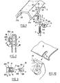
- la figure 1 montre schématiquement un premier exemple de réalisation du dispositif selon l'invention, ainsi que le garde-boue et la tringle associés ;
- la figure 2 est une vue en coupe longitudinale du dispositif selon la ligne II-II de la figure 1;
- la figure 3 est une vue en coupe selon la ligne III-III de la figure 2 montrant également la tringle et le bouchon de blocage de la tringle ;
- la figure 4 est une vue en coupe similaire à la figure 2 avec le garde-boue en place illustrant les moyens de retenue et de butée ;
- la figure 5 montre en coupe similaire à la figure 4 un deuxième exemple de réalisation du dispositif selon l'invention, illustrant les moyens de retenue ;
- la figure 6 est une vue en coupe du dispositif de la figure 5 montrant les moyens de butée ;
- la figure 7 est une vue en élévation du dispositif selon la flèche VII de la figure 6 ;
- la figure 8 est une vue en coupe similaire à la figure 6 illustrant une première variante de réalisation des moyens de butée du dispositif ;
- la figure 9 est une vue en élévation du dispositif selon la flèche IX de la figure 8 ;
- la figure 10 est une vue en perpective montrant une deuxième variante de réalisation des moyens de butée du dispositif et le garde-boue associé ;
- la figure 11 est une vue de côté montrant un troisième exemple de réalisation du dispositif selon l'invention ;
- la figure 12 est une vue en coupe longitudinale du dispositif de la figure 11 ;
- la figure 13 est une vue en coupe selon la ligne XIII-XIII de la figure 11;
- la figure 14 est une vue en élévation selon la flèche XIV de la figure 12 ; et
- les figures 15A et 15B représentent respectivement une vue en coupe d'un exemple particulier de réalisation du corps d'un dispositif selon l'invention et une vue en coupe d'un écrou conique de fixation mis en oeuvre dans ce dispositif.
- Figure 1 schematically shows a first embodiment of the device according to the invention, as well as the mudguard and the associated rod;
- Figure 2 is a longitudinal sectional view of the device along the line II-II of Figure 1;
- Figure 3 is a sectional view along line III-III of Figure 2 also showing the rod and the locking plug of the rod;
- Figure 4 is a sectional view similar to Figure 2 with the mudguard in place illustrating the retaining and stop means;
- Figure 5 shows in section similar to Figure 4 a second embodiment of the device according to the invention, illustrating the retaining means;
- Figure 6 is a sectional view of the device of Figure 5 showing the stop means;
- Figure 7 is an elevational view of the device according to arrow VII of Figure 6;
- Figure 8 is a sectional view similar to Figure 6 illustrating a first alternative embodiment of the stop means of the device;
- Figure 9 is an elevational view of the device according to arrow IX of Figure 8;
- Figure 10 is a perspective view showing a second alternative embodiment of the stop means of the device and the associated mudguard;
- Figure 11 is a side view showing a third embodiment of the device according to the invention;
- Figure 12 is a longitudinal sectional view of the device of Figure 11;
- Figure 13 is a sectional view along line XIII-XIII of Figure 11;
- Figure 14 is an elevational view along arrow XIV of Figure 12; and
- Figures 15A and 15B respectively show a sectional view of a particular embodiment of the body of a device according to the invention and a sectional view of a conical fixing nut used in this device.
En se référant aux figures 1 à 4, le dispositif de fixation 1 selon
l'invention est destiné à fixer un garde-boue 2 à une tringle 3 partant du
moyeu de la roue du bicyclette (non représenté). Deux dispositifs de
fixation 1 sont utilisés pour fixer les deux bords longitudinaux 4A et 4B
du garde-boue 2.Referring to Figures 1 to 4, the fixing device 1 according to
the invention is intended to fix a
Le dispositif de fixation 1 comporte un corps allongé 5 dans lequel
est prévu un passage 6 pour la tringle 3 et fermé par un fond 7. Pour la
fixation du dispositif 1 à la tringle 3, une ouverture 9 est ménagée dans
le corps 5 débouchant perpendiculairement dans le passage 6 coopérant
avec un bouchon 10 ayant une tête 11 et deux pattes de blocage 12A,
12B s'étendant dans des plans parallèles. Les faces en regard l'une de
l'autre des pattes de blocage 12A, 12B sont munies de stries 13
parallèles s'étendant dans une direction perpendiculaire au bord avant
respectif 14A, 14B de chacune des pattes 12A, 12B. Sur la tringle 3
sont également ménagées des stries 15 dans des plans perpendiculaires à
l'axe de la tringle 3 et sur deux zones latérales diamétralement opposées.
Le diamètre du passage 6 dans le corps 5 est tel que, une fois la tringle 3
introduite, le bouchon 10 peut être insérer par l'ouverture 9 de manière
que ses deux pattes de blocages 12A, 12B, encadrent la tringle 3, les
stries 13 du bouchon 10 et les stries 15 de la tringle s'interengageant
pour obtenir le blocage du dispositif 1 sur la tringle. La hauteur des stries
15 sur les zones latérales de la tringle est telle qu'un réglage du dispositif
est possible selon la bicyclette à équiper. Un décrochement 18, ménagé
dans l'épaisseur de la paroi avant 18 du corps 5 en regard de l'ouverture
9, sert à caler les extrémités des pattes de blocage 12A, 12B lorsque le
bouchon 10 est en place.The fixing device 1 comprises an
Pour la fixation du garde-boue, une patte de fixation 20 est
ménagée en saillie à l'opposé de l'ouverture 9. Comme on le voit sur la
figure 3 notamment, la largeur de la patte 20 est sensiblement égale à la
largeur ou diamètre du corps 5. La patte 20 comporte une zone de
raccordement 21 avec le corps 5 du dispositif au dessus du
décrochement 18. La patte de fixation 20 s'étend globalement en
direction de l'extrémité supérieure 22 du corps 5 à distance de la paroi
extérieure 24 du corps 5 de manière à ce qu'une rainure 25 soit définie
entre cette patte de fixation 20 et ladite paroi 24. Une portion
d'extrémité 26 de la patte 20 est recourbée en direction du corps allongé
5 de manière que la rainure 25 présente une forme complémentaire à un
bourrelet 27A, 27B terminant respectivement dans le bord longitudinal
4A, 4B du garde-boue et de manière que la rainure soit pourvue d'un fond
élargi 30.For fixing the mudguard, a fixing
Le dispositif 1 ainsi que le bouchon 10 et un cordon 32 reliant le
bouchon au corps 5 sont fabriqués d'un seul tenant par moulage d'un
matériau synthétique. Ce matériau autorise une certaine flexibilité de la
patte de fixation 20 autour de sa zone de raccordement et permet au
bourrelet du bord du garde-boue d'être introduit jusque dans le fond élargi
30 de la rainure 25, la patte 20 reprenant ensuite sa position de repos. The device 1 as well as the
Selon l'invention, des moyens de butée sont également prévus
pour empêcher un déplacement longitudinal du garde-boue. Ils
comprennent un bossage 35 ménagé en saillie sur l'extérieur du garde-boue
dans le prolongement du bord longitudinal 4A, 4B du garde-boue. Le
bossage 35 présente une arrête saillante 36, deux bords latéraux 37A et
37B et un bord avant 38 qui s'étend jusqu'au bord longitudinal 4A, 4B.
La patte de fixation 20 est adaptée à être introduite dans le bossage 35,
de sorte que la butée de ses bords latéraux 40A, 40B contre la face
intérieure des bords latéraux 37A, 37B du bossage, empêche le
déplacement longitudinal du garde-boue.According to the invention, stop means are also provided
to prevent longitudinal movement of the mudguard. They
include a
Sur les figures 5 à 7, est représenté un autre exemple de
réalisation dans lequel, le dispositif est constitué de demi-coquilles arrière
41 et avant 42 qui viennent enserrer la tringle en comportant chacune à
cet effet une rainure de section demi-circulaire sur toute sa hauteur, les
deux demi-coquilles étant assemblées et fixées à la tringle à l'aide d'une
vis de serrage (non représentée) introduite dans deux perçages taraudés
43A, 43B ménagés perpendiculairement et dans le prolongement l'un de
l'autre dans les deux demi-coquilles. L'extrémité inférieure des demi-coquilles
est conformée en pointe. La rainure de retenue, référencée 45
ici, du bourrelet 27A, 27B, du garde-boue est ménagée dans la demi-coquille
avant 42 laquelle présente à cet effet une plus grande épaisseur
que la demi-coquille arrière 43. La rainure 45 comporte un fond élargi 46
de forme complémentaire au bourrelet 27A, 27B et une portion inclinée
48 dans laquelle se trouve le bord du garde-boue en arrière du bourrelet.
Comme on le voit sur la figure 6, pour réaliser les moyens de butée
empêchant le déplacement dans le sens longitudinal du garde-boue, la
rainure 45 présente une zone élargie du côté du passage 47 de la tringle,
centré par rapport à celui-ci, et formant un logement 49 dans lequel le
bossage 35 en saillie sur l'extérieur du garde-boue est destiné à être
introduit. Le logement 49 comporte une paroi arrière 49a destinée à venir
au contact du bord avant droit 37B du bossage 35 et une paroi
supérieure 49b inclinée reliant la paroi arrière 49a à l'entrée 49c de la
rainure 45 et des parois latérales 50A, 50B (voir figure 7), les bords
latéraux 37A, 37B du bossage venant en butée contre ces parois
latérales. In FIGS. 5 to 7, another example of
embodiment in which the device consists of rear half-
Les figures 8 et 9 montrent, par rapport à l'exemple des figures 5 à
7, une première variante de réalisation des moyens de butée dans
laquelle, un bossage 55 est cette fois ménagé en saillie vers l'intérieur du
garde-boue, coopérant avec un logement cylindrique 56 ménagé dans la
demi-coquille avant 42 en direction de la paroi avant 42a de celle-ci et
débouchant dans la rainure de retenue 45 du garde-boue.Figures 8 and 9 show, compared to the example of Figures 5 to
7, a first alternative embodiment of the stop means in
which, a
La figure 10 montre une deuxième variante de réalisation des
moyens de butée comprenant une paroi 60 ménagée perpendiculairement
dans le fond de la rainure 45 à distance des extrémités de la rainure
introduite dans une encoche 61 ménagée transversalement dans le bord
du garde-boue 2.FIG. 10 shows a second alternative embodiment of the
stop means comprising a wall 60 formed perpendicularly
in the bottom of the
Les figures 11 à 14 illustrent un troisième exemple de réalisation
de l'invention. Cet exemple présente des points communs avec le premier
exemple montré aux figures 1 à 4, en ce qui concerne le corps 5 (à
l'exception du décrochement 18 qui n'est pas reproduit ici) et les moyens
de fixation du dispositif à la tringle, qui ne seront donc pas décrits ici. Le
dispositif selon cet exemple est caractérisé par la présence de deux
pattes de fixation 70a et 70b, possédant, comme on le voit mieux sur la
figure 12, des zones de raccordement respectivement 71a, 71b, au corps
5 du dispositif situées latéralement, les pattes encadrant ainsi le corps 5
en s'étendant vers l'avant de celui-ci. Plus précisément ici et comme on
le voit sur la figure 13, les pattes comprennent une première portion 72a,
72b leur permettant de s'écarter du corps 5 et vers l'avant de celui-ci,
puis une seconde portion 73a, 73b dans laquelle sont ménagés les
moyens de fixation du garde-boue, lesdites seconde portions de chaque
patte s'étendant globalement dans des plans parallèles. Comme on le voit
de côté sur les figures 11 et 12, la seconde portion 73a, 73b comprend
une partie 74a, 74b recourbée vers le haut du corps 5 formant, avec la
paroi avant du corps 5, le fond respectivement 75a, 75b d'une rainure
76a, 76b, adapté à coopérer avec le bourrelet longitudinal 27A, 27B du
garde-boue et une partie d'extrémité 77a, 77b recourbée vers l'extérieur
du dispositif de manière à former une surface supérieure 78a, 78b
adaptée à venir en contact avec la face intérieure du garde-boue. Dans
cet exemple de réalisation, il est prévu en outre une patte supérieure 80
située entre les pattes de fixation 70a et 70b et ayant une zone de
raccordement 81 au corps 5 située au dessus du plan contenant les
zones de raccordement 71a, 71b desdites pattes de fixation. Cette patte
supérieure 80 présente une face inférieure 82 s'étendant dans un plan
parallèle à celui contenant la face supérieure 78a, 78b de la partie
d'extrémité des pattes de fixation et adapté à venir au contact de la
surface extérieure de la paroi du garde-boue. Les moyens de butée
empêchant le déplacement dans le sens longitudinal du garde-boue sont
ici constitués d'une paroi 79a, 79b disposée dans chaque rainure 76a,
76b coopérant chacune avec une encoche, ménagée à cet effet
transversalement dans le bord longitudinal du garde-boue, comme c'est le
cas dans la variante représentée à la figure 10.Figures 11 to 14 illustrate a third embodiment
of the invention. This example has points in common with the first
example shown in FIGS. 1 to 4, with regard to the body 5 (to
the exception of the
Lorsque le garde-boue est en place, son bourrelet longitudinal 27A,
27B, est logé dans le fond 75a, 75b, des deux rainures 76a, 76b, des
pattes de fixation, ses encoches étant placées sur les parois de butée
79a, 79b correspondantes. La paroi du garde-boue en arrière du bourrelet
27A, 27B est pincée par les portions d'extrémité 77a, 77b des pattes de
fixation et par la patte supérieure 80, permettant ainsi d'assurer une
meilleure retenue du bord longitudinal du garde-boue.When the mudguard is in place, its
Dans un mode de réalisation particulièrement avantageux illustré
par les figures 15A et 15B, le dispositif de fixation selon l'invention 150
comprend, au titre des moyens de fixation à la tringle, dans la partie du
serre-tringle prévue pour coiffer la tringle, deux ailes de resserrage 155,
156 définissant un passage de tringle 160 sensiblement conique avec
une surface extérieure conique filetée 154 coopérant avec un écrou
conique 151 taraudé dans sa surface intérieure 153. Ce mode de fixation
de la tringle au dispositif selon l'invention est particulièrement efficace
car le serrage de l'écrou conique garantit un verrouillage de la position
relative de la tringle dans le passage de tringle.In a particularly advantageous embodiment illustrated
by FIGS. 15A and 15B, the fixing device according to the
Il va de soi que d'autres variantes de réalisation sont possibles,
notamment en ce qui concerne les moyens de fixation du dispositif à la
tringle. Par exemple pour améliorer le guidage de l'introduction du
bouchon de fixation coopérant avec la tringle et son maintien on peut
prévoir des chanfreins. Egalement, à la place ou en complément du
décrochement 18 visible sur la figure 3 qui permet de caler l'extrémité
des pattes du bouchon de fixation, on pourrait prévoir des décrochements
dans la paroi du corps pour loger la tête du bouchon. It goes without saying that other variant embodiments are possible,
in particular as regards the means of fixing the device to the
rod. For example to improve the guidance of the introduction of the
fixing plug cooperating with the rod and its maintenance it is possible
provide chamfers. Also, in place of or in addition to the
En variante, on pourrait également prévoir des moyens de guidage du positionnement de la tringle, comme une conformation concave de la face intérieure de la paroi du corps dans laquelle viendrait se caler la tringle, ou bien un fond pour ledit corps dans lequel serait ménagé un perçage oblong. De même au niveau de l'ouverture dans laquelle est introduit le bouchon, on pourrait prévoir des moyens de positionnement de la tringle de ce type, par exemple une ou plusieurs cloisons raccordées perpendiculairement à la paroi du corps et comportant un perçage oblong pou le passage de la tringle.Alternatively, one could also provide guide means the positioning of the rod, as a concave conformation of the inside face of the wall of the body in which the rod, or a bottom for said body in which would be formed a oblong drilling. Likewise at the opening in which is introduced the plug, positioning means could be provided rod of this type, for example one or more partitions connected perpendicular to the wall of the body and having an oblong hole for the passage of the rod.
Par ailleurs, au lieu d'avoir deux demi-coquilles, on pourrait avoir à la place un seul corps de dispositif dans lequel serait par exemple ménagé un passage pour la tringle.Furthermore, instead of having two half-shells, we could have to places a single device body in which, for example, would be provided a passage for the rod.
Le dispositif pourrait comporter également un deuxième passage de tringle.The device could also include a second passage of rod.
Par ailleurs encore, on peut alléger le dispositif et/ou améliorer l'élasticité, par exemple de la patte de fixation supérieure, en enlevant de la matière dans les parties où l'épaisseur le permet.Furthermore, the device can be made lighter and / or improved elasticity, for example of the upper fixing lug, removing from the material in the parts where the thickness allows it.
Claims (21)
Applications Claiming Priority (3)
| Application Number | Priority Date | Filing Date | Title |
|---|---|---|---|
| FR9903251 | 1999-03-16 | ||
| FR9903251A FR2791030B1 (en) | 1999-03-16 | 1999-03-16 | FIXING DEVICE FOR BIKE FENDERS |
| EP00400734A EP1036731B1 (en) | 1999-03-16 | 2000-03-16 | Bicycle mudguard mounting arrangement |
Related Parent Applications (1)
| Application Number | Title | Priority Date | Filing Date |
|---|---|---|---|
| EP00400734A Division EP1036731B1 (en) | 1999-03-16 | 2000-03-16 | Bicycle mudguard mounting arrangement |
Publications (3)
| Publication Number | Publication Date |
|---|---|
| EP1331165A2 true EP1331165A2 (en) | 2003-07-30 |
| EP1331165A3 EP1331165A3 (en) | 2004-12-15 |
| EP1331165B1 EP1331165B1 (en) | 2006-11-02 |
Family
ID=9543262
Family Applications (2)
| Application Number | Title | Priority Date | Filing Date |
|---|---|---|---|
| EP00400734A Expired - Lifetime EP1036731B1 (en) | 1999-03-16 | 2000-03-16 | Bicycle mudguard mounting arrangement |
| EP03009142A Expired - Lifetime EP1331165B1 (en) | 1999-03-16 | 2000-03-16 | Bicycle mudguard mounting arrangement |
Family Applications Before (1)
| Application Number | Title | Priority Date | Filing Date |
|---|---|---|---|
| EP00400734A Expired - Lifetime EP1036731B1 (en) | 1999-03-16 | 2000-03-16 | Bicycle mudguard mounting arrangement |
Country Status (4)
| Country | Link |
|---|---|
| EP (2) | EP1036731B1 (en) |
| AT (1) | ATE259322T1 (en) |
| DE (2) | DE60031728T2 (en) |
| FR (1) | FR2791030B1 (en) |
Cited By (1)
| Publication number | Priority date | Publication date | Assignee | Title |
|---|---|---|---|---|
| EP1884456A1 (en) | 2006-07-28 | 2008-02-06 | Orion-Italy Componenti Biciclette Srl | Device for fixing the mudguards of cycles at the upper end of a mudguard support bracket rod |
Families Citing this family (16)
| Publication number | Priority date | Publication date | Assignee | Title |
|---|---|---|---|---|
| DE20008005U1 (en) * | 2000-05-05 | 2000-07-20 | Sks Metaplast Scheffer Klute | Fastening device for a mudguard |
| EP1221407A1 (en) * | 2001-01-03 | 2002-07-10 | Kuei C. Huang | Secure fastening means for bicycle mudguard |
| FR2821330A1 (en) * | 2001-02-28 | 2002-08-30 | Zefal | Connector for bicycle mudguard to wheel hub or carrier is made from moulded material with end shaped to grip mudguard edge |
| ITVR20010099A1 (en) * | 2001-09-13 | 2003-03-13 | San Giorgio Bicycle Components | LOCKING DEVICE FOR A BICYCLE MUDGUARD CONSTITUTED BY TWO INTERCONNECTED ELEMENTS. |
| GB2383314B (en) * | 2001-12-18 | 2005-02-16 | Spencer Mfg Ltd | Connecting device |
| DE20300726U1 (en) | 2003-01-17 | 2003-03-20 | Sks Metaplast Scheffer Klute | Device for attaching struts to hold a mudguard on the frame of a two-wheeler |
| NL1022857C2 (en) * | 2003-03-06 | 2004-09-09 | Lepper Beheer B V | Coupling, especially for mounting bicycle mud guard, includes fastener system with rotary cylinder for fixing mud guard bar into position inside casing |
| ITVI20030082A1 (en) * | 2003-04-16 | 2004-10-17 | Rpz Di Golin Maria | CLAMP DEVICE FOR ASSEMBLING A FENDER |
| ITVI20060021A1 (en) | 2006-01-19 | 2007-07-20 | Ivan Passuello | SAFETY RELEASE BODY, PARTICULARLY FOR SINGLE AUCTION AND FENDER |
| EP1944225A3 (en) * | 2007-01-12 | 2009-11-04 | sks-metaplast SCHEFFER-KLUTE GMBH | Bicycle mudguard mounting arrangement and protective cap |
| IT1400657B1 (en) * | 2010-07-05 | 2013-06-28 | Roto Societa A Responsabilita Limitata | LOCKING AND SUPPORT ORGAN, PARTICULARLY FOR BICYCLES AND SIMILAR FENDERS, AND RESPECT MUDGUARD. |
| GB2492842A (en) * | 2011-07-14 | 2013-01-16 | Young Operations Ltd H | Bicycle mudguard assembly |
| FR3011807B1 (en) * | 2013-10-14 | 2017-05-12 | Decathlon Sa | MOUTH GUARD WITH ARTICULATED HEAD |
| FR3011806B1 (en) * | 2013-10-14 | 2017-04-14 | Decathlon Sa | Adjustable rail mudguard |
| TWI673193B (en) * | 2018-07-06 | 2019-10-01 | 瑞振工業股份有限公司 | Buckle type soil removal support frame |
| TWI749952B (en) * | 2020-12-17 | 2021-12-11 | 瑞振工業股份有限公司 | Soil removal fixture |
Citations (2)
| Publication number | Priority date | Publication date | Assignee | Title |
|---|---|---|---|---|
| DE29614001U1 (en) | 1996-08-13 | 1996-09-26 | Sks Metaplast Scheffer Klute | Device for attaching a strut to a mudguard |
| EP0742137A2 (en) | 1995-05-11 | 1996-11-13 | ZINCATURA SAN GIORGIO s.n.c. di DE POLI GAVINO & C. | Attachment means for a bicycle mudguard |
Family Cites Families (4)
| Publication number | Priority date | Publication date | Assignee | Title |
|---|---|---|---|---|
| GB190224477A (en) * | 1902-11-08 | 1903-10-22 | Henry Sidebottom | Improvements in Means for Coupling Metallic Cords, Cables and the like |
| GB303989A (en) * | 1927-12-07 | 1929-01-17 | William Albert Gorton | Improvements in stays of cycle mudguards, luggage carriers, and the like |
| GB2278323A (en) * | 1993-05-25 | 1994-11-30 | Webb Ronald R | Fixing stays to mudguards |
| IT245373Y1 (en) * | 1998-06-24 | 2002-03-20 | San Giorgio Snc Di De Poli Liv | LOCKING DEVICE OF A FENDER FOR BICYCLES |
-
1999
- 1999-03-16 FR FR9903251A patent/FR2791030B1/en not_active Expired - Fee Related
-
2000
- 2000-03-16 AT AT00400734T patent/ATE259322T1/en not_active IP Right Cessation
- 2000-03-16 DE DE60031728T patent/DE60031728T2/en not_active Expired - Fee Related
- 2000-03-16 DE DE60008155T patent/DE60008155T2/en not_active Expired - Fee Related
- 2000-03-16 EP EP00400734A patent/EP1036731B1/en not_active Expired - Lifetime
- 2000-03-16 EP EP03009142A patent/EP1331165B1/en not_active Expired - Lifetime
Patent Citations (2)
| Publication number | Priority date | Publication date | Assignee | Title |
|---|---|---|---|---|
| EP0742137A2 (en) | 1995-05-11 | 1996-11-13 | ZINCATURA SAN GIORGIO s.n.c. di DE POLI GAVINO & C. | Attachment means for a bicycle mudguard |
| DE29614001U1 (en) | 1996-08-13 | 1996-09-26 | Sks Metaplast Scheffer Klute | Device for attaching a strut to a mudguard |
Cited By (1)
| Publication number | Priority date | Publication date | Assignee | Title |
|---|---|---|---|---|
| EP1884456A1 (en) | 2006-07-28 | 2008-02-06 | Orion-Italy Componenti Biciclette Srl | Device for fixing the mudguards of cycles at the upper end of a mudguard support bracket rod |
Also Published As
| Publication number | Publication date |
|---|---|
| EP1036731A1 (en) | 2000-09-20 |
| EP1036731B1 (en) | 2004-02-11 |
| DE60008155D1 (en) | 2004-03-18 |
| EP1331165A3 (en) | 2004-12-15 |
| DE60008155T2 (en) | 2004-09-16 |
| DE60031728T2 (en) | 2007-05-31 |
| FR2791030B1 (en) | 2001-06-01 |
| EP1331165B1 (en) | 2006-11-02 |
| FR2791030A1 (en) | 2000-09-22 |
| DE60031728D1 (en) | 2006-12-14 |
| ATE259322T1 (en) | 2004-02-15 |
Similar Documents
| Publication | Publication Date | Title |
|---|---|---|
| EP1036731B1 (en) | Bicycle mudguard mounting arrangement | |
| EP0327440B1 (en) | Connection between a heat exchanger and a tubular member | |
| FR2473151A1 (en) | PIPE CONNECTION DEVICE | |
| FR2825527A1 (en) | CORNER ACCESSORY FOR CHUTE | |
| FR2735960A1 (en) | Bar to pull cover on to seat cushion | |
| EP3670988A1 (en) | Clamping device comprising a belt and a sealing ring | |
| FR2746721A1 (en) | Seat runner | |
| EP0683327B1 (en) | Fastener for cables, pipes or the like | |
| EP0742329B1 (en) | Vehicle locking device comprising improved mounting means for trim cap | |
| EP0497636B1 (en) | Mounting arrangement for a vehicle bumper | |
| EP0742137A2 (en) | Attachment means for a bicycle mudguard | |
| FR2786540A1 (en) | Accessory mounting device for any type of article but in particular an inspection lamp | |
| EP0991155B1 (en) | Cabinet, especially for electrical equipment, having the rear wall with at least one hole covered with a cap | |
| FR2766864A1 (en) | DEVICE FOR CONVICTING A SUNLOCK OF A MOTOR VEHICLE | |
| FR2696917A1 (en) | Attachment of seat and backrest components of chair etc. - uses concealed pin projections with elastic snap fit to engage plastics inserts, linking plastics casing to wooden cushion support plate | |
| FR2629878A1 (en) | FIXING DEVICE | |
| EP0911575B1 (en) | Lighting or signalling device comprising a plug for connection to a vehicle | |
| FR2708242A1 (en) | Wiper device with articulation of elements. | |
| WO2002022435A1 (en) | Kit for fixing a water-bottle carrier | |
| FR2787554A1 (en) | INTERMEDIATE FIXING ELEMENT OF A REFLECTOR ON A SUPPORT PART OF A MOTOR VEHICLE PROJECTOR, AND PROJECTOR COMPRISING SUCH AN ELEMENT | |
| WO2022200702A1 (en) | Motor vehicle bumper skin | |
| FR2536128A1 (en) | Elastic clip for fixing a panel to a support | |
| FR2836188A1 (en) | Fastening for tubular components such as handle and guard rail has intermediate assembly component with two sets of locking elements | |
| EP1058362A1 (en) | Electrical equipment box with link between its two elements | |
| FR2737763A1 (en) | Sealing joint between duct and container with opening - has circular side wall whose external surface has peripheral groove delimiting two wall parts, one inclined and other parallel to geometrical axis, lip moulded to side wall defining central opening |
Legal Events
| Date | Code | Title | Description |
|---|---|---|---|
| PUAI | Public reference made under article 153(3) epc to a published international application that has entered the european phase |
Free format text: ORIGINAL CODE: 0009012 |
|
| AC | Divisional application: reference to earlier application |
Ref document number: 1036731 Country of ref document: EP Kind code of ref document: P |
|
| AK | Designated contracting states |
Designated state(s): AT BE CH CY DE DK ES FI FR GB GR IE IT LI LU MC NL PT SE |
|
| PUAL | Search report despatched |
Free format text: ORIGINAL CODE: 0009013 |
|
| AK | Designated contracting states |
Kind code of ref document: A3 Designated state(s): AT BE CH CY DE DK ES FI FR GB GR IE IT LI LU MC NL PT SE |
|
| RAP1 | Party data changed (applicant data changed or rights of an application transferred) |
Owner name: ZEFAL |
|
| 17P | Request for examination filed |
Effective date: 20050608 |
|
| AKX | Designation fees paid |
Designated state(s): DE FR NL |
|
| GRAP | Despatch of communication of intention to grant a patent |
Free format text: ORIGINAL CODE: EPIDOSNIGR1 |
|
| GRAS | Grant fee paid |
Free format text: ORIGINAL CODE: EPIDOSNIGR3 |
|
| GRAA | (expected) grant |
Free format text: ORIGINAL CODE: 0009210 |
|
| AC | Divisional application: reference to earlier application |
Ref document number: 1036731 Country of ref document: EP Kind code of ref document: P |
|
| AK | Designated contracting states |
Kind code of ref document: B1 Designated state(s): DE FR NL |
|
| REF | Corresponds to: |
Ref document number: 60031728 Country of ref document: DE Date of ref document: 20061214 Kind code of ref document: P |
|
| PLBE | No opposition filed within time limit |
Free format text: ORIGINAL CODE: 0009261 |
|
| STAA | Information on the status of an ep patent application or granted ep patent |
Free format text: STATUS: NO OPPOSITION FILED WITHIN TIME LIMIT |
|
| 26N | No opposition filed |
Effective date: 20070803 |
|
| PGFP | Annual fee paid to national office [announced via postgrant information from national office to epo] |
Ref country code: NL Payment date: 20080331 Year of fee payment: 9 |
|
| PGFP | Annual fee paid to national office [announced via postgrant information from national office to epo] |
Ref country code: DE Payment date: 20080325 Year of fee payment: 9 |
|
| PGFP | Annual fee paid to national office [announced via postgrant information from national office to epo] |
Ref country code: FR Payment date: 20080325 Year of fee payment: 9 |
|
| NLV4 | Nl: lapsed or anulled due to non-payment of the annual fee |
Effective date: 20091001 |
|
| REG | Reference to a national code |
Ref country code: FR Ref legal event code: ST Effective date: 20091130 |
|
| PG25 | Lapsed in a contracting state [announced via postgrant information from national office to epo] |
Ref country code: DE Free format text: LAPSE BECAUSE OF NON-PAYMENT OF DUE FEES Effective date: 20091001 |
|
| PG25 | Lapsed in a contracting state [announced via postgrant information from national office to epo] |
Ref country code: NL Free format text: LAPSE BECAUSE OF NON-PAYMENT OF DUE FEES Effective date: 20091001 |
|
| PG25 | Lapsed in a contracting state [announced via postgrant information from national office to epo] |
Ref country code: FR Free format text: LAPSE BECAUSE OF NON-PAYMENT OF DUE FEES Effective date: 20091123 |