EP1329601A1 - Materiau etanche de fixation pour pot catalytique et procede de fabrication de celui-ci - Google Patents
Materiau etanche de fixation pour pot catalytique et procede de fabrication de celui-ci Download PDFInfo
- Publication number
- EP1329601A1 EP1329601A1 EP01976709A EP01976709A EP1329601A1 EP 1329601 A1 EP1329601 A1 EP 1329601A1 EP 01976709 A EP01976709 A EP 01976709A EP 01976709 A EP01976709 A EP 01976709A EP 1329601 A1 EP1329601 A1 EP 1329601A1
- Authority
- EP
- European Patent Office
- Prior art keywords
- holding
- sealing material
- catalyst carrier
- fiber aggregate
- alumina
- Prior art date
- Legal status (The legal status is an assumption and is not a legal conclusion. Google has not performed a legal analysis and makes no representation as to the accuracy of the status listed.)
- Granted
Links
Images

Classifications
-
- D—TEXTILES; PAPER
- D04—BRAIDING; LACE-MAKING; KNITTING; TRIMMINGS; NON-WOVEN FABRICS
- D04H—MAKING TEXTILE FABRICS, e.g. FROM FIBRES OR FILAMENTARY MATERIAL; FABRICS MADE BY SUCH PROCESSES OR APPARATUS, e.g. FELTS, NON-WOVEN FABRICS; COTTON-WOOL; WADDING ; NON-WOVEN FABRICS FROM STAPLE FIBRES, FILAMENTS OR YARNS, BONDED WITH AT LEAST ONE WEB-LIKE MATERIAL DURING THEIR CONSOLIDATION
- D04H1/00—Non-woven fabrics formed wholly or mainly of staple fibres or like relatively short fibres
- D04H1/40—Non-woven fabrics formed wholly or mainly of staple fibres or like relatively short fibres from fleeces or layers composed of fibres without existing or potential cohesive properties
- D04H1/44—Non-woven fabrics formed wholly or mainly of staple fibres or like relatively short fibres from fleeces or layers composed of fibres without existing or potential cohesive properties the fleeces or layers being consolidated by mechanical means, e.g. by rolling
- D04H1/46—Non-woven fabrics formed wholly or mainly of staple fibres or like relatively short fibres from fleeces or layers composed of fibres without existing or potential cohesive properties the fleeces or layers being consolidated by mechanical means, e.g. by rolling by needling or like operations to cause entanglement of fibres
-
- F—MECHANICAL ENGINEERING; LIGHTING; HEATING; WEAPONS; BLASTING
- F01—MACHINES OR ENGINES IN GENERAL; ENGINE PLANTS IN GENERAL; STEAM ENGINES
- F01N—GAS-FLOW SILENCERS OR EXHAUST APPARATUS FOR MACHINES OR ENGINES IN GENERAL; GAS-FLOW SILENCERS OR EXHAUST APPARATUS FOR INTERNAL COMBUSTION ENGINES
- F01N3/00—Exhaust or silencing apparatus having means for purifying, rendering innocuous, or otherwise treating exhaust
- F01N3/08—Exhaust or silencing apparatus having means for purifying, rendering innocuous, or otherwise treating exhaust for rendering innocuous
- F01N3/10—Exhaust or silencing apparatus having means for purifying, rendering innocuous, or otherwise treating exhaust for rendering innocuous by thermal or catalytic conversion of noxious components of exhaust
- F01N3/24—Exhaust or silencing apparatus having means for purifying, rendering innocuous, or otherwise treating exhaust for rendering innocuous by thermal or catalytic conversion of noxious components of exhaust characterised by constructional aspects of converting apparatus
- F01N3/28—Construction of catalytic reactors
-
- C—CHEMISTRY; METALLURGY
- C04—CEMENTS; CONCRETE; ARTIFICIAL STONE; CERAMICS; REFRACTORIES
- C04B—LIME, MAGNESIA; SLAG; CEMENTS; COMPOSITIONS THEREOF, e.g. MORTARS, CONCRETE OR LIKE BUILDING MATERIALS; ARTIFICIAL STONE; CERAMICS; REFRACTORIES; TREATMENT OF NATURAL STONE
- C04B35/00—Shaped ceramic products characterised by their composition; Ceramics compositions; Processing powders of inorganic compounds preparatory to the manufacturing of ceramic products
- C04B35/622—Forming processes; Processing powders of inorganic compounds preparatory to the manufacturing of ceramic products
- C04B35/62227—Forming processes; Processing powders of inorganic compounds preparatory to the manufacturing of ceramic products obtaining fibres
- C04B35/62231—Forming processes; Processing powders of inorganic compounds preparatory to the manufacturing of ceramic products obtaining fibres based on oxide ceramics
- C04B35/6224—Fibres based on silica
- C04B35/62245—Fibres based on silica rich in aluminium oxide
-
- C—CHEMISTRY; METALLURGY
- C04—CEMENTS; CONCRETE; ARTIFICIAL STONE; CERAMICS; REFRACTORIES
- C04B—LIME, MAGNESIA; SLAG; CEMENTS; COMPOSITIONS THEREOF, e.g. MORTARS, CONCRETE OR LIKE BUILDING MATERIALS; ARTIFICIAL STONE; CERAMICS; REFRACTORIES; TREATMENT OF NATURAL STONE
- C04B35/00—Shaped ceramic products characterised by their composition; Ceramics compositions; Processing powders of inorganic compounds preparatory to the manufacturing of ceramic products
- C04B35/622—Forming processes; Processing powders of inorganic compounds preparatory to the manufacturing of ceramic products
- C04B35/626—Preparing or treating the powders individually or as batches ; preparing or treating macroscopic reinforcing agents for ceramic products, e.g. fibres; mechanical aspects section B
- C04B35/62605—Treating the starting powders individually or as mixtures
- C04B35/62625—Wet mixtures
- C04B35/6263—Wet mixtures characterised by their solids loadings, i.e. the percentage of solids
-
- C—CHEMISTRY; METALLURGY
- C04—CEMENTS; CONCRETE; ARTIFICIAL STONE; CERAMICS; REFRACTORIES
- C04B—LIME, MAGNESIA; SLAG; CEMENTS; COMPOSITIONS THEREOF, e.g. MORTARS, CONCRETE OR LIKE BUILDING MATERIALS; ARTIFICIAL STONE; CERAMICS; REFRACTORIES; TREATMENT OF NATURAL STONE
- C04B35/00—Shaped ceramic products characterised by their composition; Ceramics compositions; Processing powders of inorganic compounds preparatory to the manufacturing of ceramic products
- C04B35/622—Forming processes; Processing powders of inorganic compounds preparatory to the manufacturing of ceramic products
- C04B35/626—Preparing or treating the powders individually or as batches ; preparing or treating macroscopic reinforcing agents for ceramic products, e.g. fibres; mechanical aspects section B
- C04B35/62605—Treating the starting powders individually or as mixtures
- C04B35/62645—Thermal treatment of powders or mixtures thereof other than sintering
- C04B35/62675—Thermal treatment of powders or mixtures thereof other than sintering characterised by the treatment temperature
-
- C—CHEMISTRY; METALLURGY
- C04—CEMENTS; CONCRETE; ARTIFICIAL STONE; CERAMICS; REFRACTORIES
- C04B—LIME, MAGNESIA; SLAG; CEMENTS; COMPOSITIONS THEREOF, e.g. MORTARS, CONCRETE OR LIKE BUILDING MATERIALS; ARTIFICIAL STONE; CERAMICS; REFRACTORIES; TREATMENT OF NATURAL STONE
- C04B35/00—Shaped ceramic products characterised by their composition; Ceramics compositions; Processing powders of inorganic compounds preparatory to the manufacturing of ceramic products
- C04B35/622—Forming processes; Processing powders of inorganic compounds preparatory to the manufacturing of ceramic products
- C04B35/626—Preparing or treating the powders individually or as batches ; preparing or treating macroscopic reinforcing agents for ceramic products, e.g. fibres; mechanical aspects section B
- C04B35/63—Preparing or treating the powders individually or as batches ; preparing or treating macroscopic reinforcing agents for ceramic products, e.g. fibres; mechanical aspects section B using additives specially adapted for forming the products, e.g.. binder binders
- C04B35/632—Organic additives
- C04B35/634—Polymers
- C04B35/63404—Polymers obtained by reactions only involving carbon-to-carbon unsaturated bonds
- C04B35/63416—Polyvinylalcohols [PVA]; Polyvinylacetates
-
- D—TEXTILES; PAPER
- D04—BRAIDING; LACE-MAKING; KNITTING; TRIMMINGS; NON-WOVEN FABRICS
- D04H—MAKING TEXTILE FABRICS, e.g. FROM FIBRES OR FILAMENTARY MATERIAL; FABRICS MADE BY SUCH PROCESSES OR APPARATUS, e.g. FELTS, NON-WOVEN FABRICS; COTTON-WOOL; WADDING ; NON-WOVEN FABRICS FROM STAPLE FIBRES, FILAMENTS OR YARNS, BONDED WITH AT LEAST ONE WEB-LIKE MATERIAL DURING THEIR CONSOLIDATION
- D04H1/00—Non-woven fabrics formed wholly or mainly of staple fibres or like relatively short fibres
- D04H1/40—Non-woven fabrics formed wholly or mainly of staple fibres or like relatively short fibres from fleeces or layers composed of fibres without existing or potential cohesive properties
- D04H1/42—Non-woven fabrics formed wholly or mainly of staple fibres or like relatively short fibres from fleeces or layers composed of fibres without existing or potential cohesive properties characterised by the use of certain kinds of fibres insofar as this use has no preponderant influence on the consolidation of the fleece
- D04H1/4209—Inorganic fibres
-
- C—CHEMISTRY; METALLURGY
- C04—CEMENTS; CONCRETE; ARTIFICIAL STONE; CERAMICS; REFRACTORIES
- C04B—LIME, MAGNESIA; SLAG; CEMENTS; COMPOSITIONS THEREOF, e.g. MORTARS, CONCRETE OR LIKE BUILDING MATERIALS; ARTIFICIAL STONE; CERAMICS; REFRACTORIES; TREATMENT OF NATURAL STONE
- C04B2235/00—Aspects relating to ceramic starting mixtures or sintered ceramic products
- C04B2235/02—Composition of constituents of the starting material or of secondary phases of the final product
- C04B2235/30—Constituents and secondary phases not being of a fibrous nature
- C04B2235/34—Non-metal oxides, non-metal mixed oxides, or salts thereof that form the non-metal oxides upon heating, e.g. carbonates, nitrates, (oxy)hydroxides, chlorides
- C04B2235/3427—Silicates other than clay, e.g. water glass
- C04B2235/3463—Alumino-silicates other than clay, e.g. mullite
-
- C—CHEMISTRY; METALLURGY
- C04—CEMENTS; CONCRETE; ARTIFICIAL STONE; CERAMICS; REFRACTORIES
- C04B—LIME, MAGNESIA; SLAG; CEMENTS; COMPOSITIONS THEREOF, e.g. MORTARS, CONCRETE OR LIKE BUILDING MATERIALS; ARTIFICIAL STONE; CERAMICS; REFRACTORIES; TREATMENT OF NATURAL STONE
- C04B2235/00—Aspects relating to ceramic starting mixtures or sintered ceramic products
- C04B2235/02—Composition of constituents of the starting material or of secondary phases of the final product
- C04B2235/30—Constituents and secondary phases not being of a fibrous nature
- C04B2235/44—Metal salt constituents or additives chosen for the nature of the anions, e.g. hydrides or acetylacetonate
- C04B2235/444—Halide containing anions, e.g. bromide, iodate, chlorite
-
- C—CHEMISTRY; METALLURGY
- C04—CEMENTS; CONCRETE; ARTIFICIAL STONE; CERAMICS; REFRACTORIES
- C04B—LIME, MAGNESIA; SLAG; CEMENTS; COMPOSITIONS THEREOF, e.g. MORTARS, CONCRETE OR LIKE BUILDING MATERIALS; ARTIFICIAL STONE; CERAMICS; REFRACTORIES; TREATMENT OF NATURAL STONE
- C04B2235/00—Aspects relating to ceramic starting mixtures or sintered ceramic products
- C04B2235/02—Composition of constituents of the starting material or of secondary phases of the final product
- C04B2235/50—Constituents or additives of the starting mixture chosen for their shape or used because of their shape or their physical appearance
- C04B2235/52—Constituents or additives characterised by their shapes
- C04B2235/5208—Fibers
- C04B2235/526—Fibers characterised by the length of the fibers
-
- C—CHEMISTRY; METALLURGY
- C04—CEMENTS; CONCRETE; ARTIFICIAL STONE; CERAMICS; REFRACTORIES
- C04B—LIME, MAGNESIA; SLAG; CEMENTS; COMPOSITIONS THEREOF, e.g. MORTARS, CONCRETE OR LIKE BUILDING MATERIALS; ARTIFICIAL STONE; CERAMICS; REFRACTORIES; TREATMENT OF NATURAL STONE
- C04B2235/00—Aspects relating to ceramic starting mixtures or sintered ceramic products
- C04B2235/02—Composition of constituents of the starting material or of secondary phases of the final product
- C04B2235/50—Constituents or additives of the starting mixture chosen for their shape or used because of their shape or their physical appearance
- C04B2235/52—Constituents or additives characterised by their shapes
- C04B2235/5208—Fibers
- C04B2235/5264—Fibers characterised by the diameter of the fibers
-
- C—CHEMISTRY; METALLURGY
- C04—CEMENTS; CONCRETE; ARTIFICIAL STONE; CERAMICS; REFRACTORIES
- C04B—LIME, MAGNESIA; SLAG; CEMENTS; COMPOSITIONS THEREOF, e.g. MORTARS, CONCRETE OR LIKE BUILDING MATERIALS; ARTIFICIAL STONE; CERAMICS; REFRACTORIES; TREATMENT OF NATURAL STONE
- C04B2235/00—Aspects relating to ceramic starting mixtures or sintered ceramic products
- C04B2235/02—Composition of constituents of the starting material or of secondary phases of the final product
- C04B2235/50—Constituents or additives of the starting mixture chosen for their shape or used because of their shape or their physical appearance
- C04B2235/52—Constituents or additives characterised by their shapes
- C04B2235/5208—Fibers
- C04B2235/5268—Orientation of the fibers
-
- C—CHEMISTRY; METALLURGY
- C04—CEMENTS; CONCRETE; ARTIFICIAL STONE; CERAMICS; REFRACTORIES
- C04B—LIME, MAGNESIA; SLAG; CEMENTS; COMPOSITIONS THEREOF, e.g. MORTARS, CONCRETE OR LIKE BUILDING MATERIALS; ARTIFICIAL STONE; CERAMICS; REFRACTORIES; TREATMENT OF NATURAL STONE
- C04B2235/00—Aspects relating to ceramic starting mixtures or sintered ceramic products
- C04B2235/70—Aspects relating to sintered or melt-casted ceramic products
- C04B2235/74—Physical characteristics
- C04B2235/76—Crystal structural characteristics, e.g. symmetry
- C04B2235/762—Cubic symmetry, e.g. beta-SiC
- C04B2235/763—Spinel structure AB2O4
-
- C—CHEMISTRY; METALLURGY
- C04—CEMENTS; CONCRETE; ARTIFICIAL STONE; CERAMICS; REFRACTORIES
- C04B—LIME, MAGNESIA; SLAG; CEMENTS; COMPOSITIONS THEREOF, e.g. MORTARS, CONCRETE OR LIKE BUILDING MATERIALS; ARTIFICIAL STONE; CERAMICS; REFRACTORIES; TREATMENT OF NATURAL STONE
- C04B2235/00—Aspects relating to ceramic starting mixtures or sintered ceramic products
- C04B2235/70—Aspects relating to sintered or melt-casted ceramic products
- C04B2235/80—Phases present in the sintered or melt-cast ceramic products other than the main phase
-
- F—MECHANICAL ENGINEERING; LIGHTING; HEATING; WEAPONS; BLASTING
- F01—MACHINES OR ENGINES IN GENERAL; ENGINE PLANTS IN GENERAL; STEAM ENGINES
- F01N—GAS-FLOW SILENCERS OR EXHAUST APPARATUS FOR MACHINES OR ENGINES IN GENERAL; GAS-FLOW SILENCERS OR EXHAUST APPARATUS FOR INTERNAL COMBUSTION ENGINES
- F01N3/00—Exhaust or silencing apparatus having means for purifying, rendering innocuous, or otherwise treating exhaust
- F01N3/08—Exhaust or silencing apparatus having means for purifying, rendering innocuous, or otherwise treating exhaust for rendering innocuous
- F01N3/10—Exhaust or silencing apparatus having means for purifying, rendering innocuous, or otherwise treating exhaust for rendering innocuous by thermal or catalytic conversion of noxious components of exhaust
- F01N3/24—Exhaust or silencing apparatus having means for purifying, rendering innocuous, or otherwise treating exhaust for rendering innocuous by thermal or catalytic conversion of noxious components of exhaust characterised by constructional aspects of converting apparatus
- F01N3/28—Construction of catalytic reactors
- F01N3/2839—Arrangements for mounting catalyst support in housing, e.g. with means for compensating thermal expansion or vibration
- F01N3/2853—Arrangements for mounting catalyst support in housing, e.g. with means for compensating thermal expansion or vibration using mats or gaskets between catalyst body and housing
Definitions
- the present invention relates to a catalytic converter, and particularly relates to a holding and sealing material for catalytic converters and a method for manufacturing the same.
- a usual exhaust gas cleaning catalytic converter comprises a catalyst carrier, a metal shell covering the outer periphery of the catalyst carrier, and a holding and sealing material disposed in a gap between the former and the latter.
- a honeycomb-shaped cogierite carrier for example, is used for the catalyst carrier, and a catalyst such as platinum is carried on the cogierite carrier.
- the holding and sealing material of the catalytic converter serves to prevent damage to the catalyst carrier due to contact between the catalyst carrier and the metal shell when the car is traveling, while preventing leakage of gas from the gap between the metal shell and the catalyst carrier.
- the holding and sealing material also serves to establish thermal insulation from the metal shell in order to make the catalyst undergo efficient reaction from the initial stage of its use.
- a suitable material capable of performing these roles is a mat-like material made of alumina-silica based ceramic fibers.
- the mat-like material made of alumina-silica based ceramic fibers is bulky. Therefore, for the holding and sealing material, assemblage in the catalyst carrier should be improved.
- techniques, which reduce the thickness of the mat-like material by impregnating a mat-like material made of inorganic fibers with an organic binder, have been proposed.
- the organic binder In the case of the holding and sealing material impregnated with the organic binder, however, when the holding and sealing material is used while it is arranged in a gap, the organic binder is decomposed due to the heat from the exhaust gas, and the decomposition gas is released into the atmosphere. At least several wt% or more of such organic binder should be used for impregnating the holding and sealing material in order to improve assemblage. Therefore, with the conventional technique, it is very difficult to achieve a low-pollution characteristic surpassing the conventionally achievable level while maintaining suitable assemblage.
- a first object of the present invention is to provide a catalytic converter having an extremely low-pollution characteristic while being excellent in durability and assemblage.
- the second object of the present invention is to provide a holding and sealing material for catalytic converters suitable for achieving the above described excellent catalytic converter, and a method for manufacturing the same.
- a holding and sealing material disposed between a catalyst carrier and a metal shell covering the catalyst carrier is provided.
- the holding and sealing material includes a fiber aggregate mainly comprised of alumina-silica based ceramic fibers having a mullite crystal content of 10 wt% or less, and the fiber aggregate having been subjected to a needle punch treatment.
- a holding and sealing material disposed between a catalyst carrier and a metal shell covering the catalyst carrier is provided.
- the holding and sealing material includes a fiber aggregate mainly comprised of alumina-silica based ceramic fibers having a mullite crystal content of 0.5 to 4 wt%, and the fiber aggregate having been subjected to a needle punch treatment.
- a holding and sealing material disposed between a catalyst carrier and a metal shell covering the catalyst carrier includes a fiber aggregate mainly comprised of alumina-silica based ceramic fibers having a mullite crystal content of 10% or less, with some of the ceramic fibers intertwined in the direction of thickness of the fiber aggregate.
- a method for manufacturing a holding and sealing material for a catalytic converter, disposed between a catalyst carrier and a metal shell covering the catalyst carrier includes the steps of performing fiber spinning using as a raw material an aqueous solution composed of a mixture of an aluminum salt, a silica sol and an organic polymer to prepare alumina-silica based ceramic fibers, stacking the alumina-silica based ceramic fibers to prepare a fiber aggregate, subjecting the fiber aggregate to a needle punch treatment, and baking the fiber aggregate, having been subjected to a needle punch treatment, to prepare a holding and sealing material comprising a fiber aggregate having a mullite crystal content of 10 wt% or less.
- a catalytic converter in a fifth aspect of the present invention, includes a catalyst carrier, a metal shell covering the catalyst carrier, and a holding and sealing material disposed between the catalyst carrier and the metal shell.
- the holding and sealing material includes a fiber aggregate mainly comprised of alumina-silica based ceramic fibers having a mullite crystal content of 10 wt% or less, and the fiber aggregate having been subjected to a needle punch treatment.
- a catalytic converter in a sixth aspect of the present invention, includes a catalyst carrier, a metal shell covering the catalyst carrier, and a holding and sealing material disposed between the catalyst carrier and the metal shell.
- the holding and sealing material includes a fiber aggregate mainly comprised of alumina-silica based ceramic fibers having a mullite crystal content of 0.5 to 4 wt%, with the fiber aggregate having been subjected to a needle punch treatment.
- a catalytic converter in the seventh aspect of the present invention, includes a catalyst carrier, a metal shell covering the catalyst carrier, and a holding and sealing material disposed between the catalyst carrier and the metal shell.
- the holding and sealing material includes a fiber aggregate mainly comprised of alumina-silica based ceramic fibers having a mullite crystal content of 10% or less, with some of the ceramic fibers intertwined in the direction of thickness of the fiber aggregate.
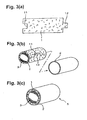
- a catalytic converter 5 for an automobile exhaust gas cleaning apparatus of one embodiment according to the present invention will be described in detail below based on Figs. 1 to 4.
- the catalytic converter 5 is provided at some position along an exhaust pipe 91 of an engine 9 along a body 92 of a vehicle. Furthermore, since the distance between the engine 9 and the catalytic converter 5 is relatively small, a high temperature exhaust gas of about 700° C to 900° C is supplied to the catalytic converter 5. In the case where the engine is a lean burn engine, an exhaust gas of higher temperature of about 900°C to 1000°C is supplied to the catalytic converter 5.
- the catalytic converter 5 comprises a cylindrical catalyst carrier 3, a metal shell 2 covering the outer periphery of the catalyst carrier 3, and a holding and sealing material 1 disposed in a gap between the catalyst carrier 3 and the metal shell 2.
- the catalyst carrier 3 is prepared using a ceramic material represented by cogierite or the like. Also, the catalyst carrier 3 is preferably a honeycomb structure having a large number of cells 31, 32 extending along the axis line. Furthermore, a catalyst such as platinum or rhodium capable of cleaning exhaust gas components is carried on the wall of cells.
- the metal shell 2 is preferably a cylindrical metal member having an O-shaped section, for example, if a press fitting method is employed for mounting. Furthermore, for the metal material for forming the cylindrical member, a metal having excellent heat resistance and impact resistance is preferably selected. If a so-called canning method is employed instead of the press fitting method, a metal shell (i.e., clam shell), which is formed by dividing the cylindrical metal member having an O-shaped section into a plurality of sections along the axis line, is used.
- a metal shell i.e., clam shell
- a cylindrical metal member which has a C-shaped or U-shaped section (i.e., a cylindrical metal member is formed with one slit (opening) extending along the axis).
- the catalyst carrier 3 with the holding and sealing material 1 fixed on the surface is disposed in the metal shell 2, the metal shell 2 is rolled up in this state, and thereafter the end of the slit opening is sealed (welded, bonded, bolted or the like). Sealing such as welding, bonding or bolting is also performed when the canning method is employed.
- the holding and sealing material 1 is an elongated mat-like material, with a concave mating portion 11 provided at one end thereof, while a convex mating portion 12 is provided at the other end.
- the convex mating portion 12 is engaged with the concave mating portion 11.
- the holding and sealing material 1 comprises a fiber aggregate mainly comprised of alumina-silica based ceramic fibers having a mullite crystal content of 0 to 10 wt%.
- the holding and sealing material 1 comprises a fiber aggregate mainly comprised of ceramic fibers made of an aluminum-silicon spinel compound containing no mullite crystal or containing 10 wt% or less of mullite crystal.
- the holding and sealing material 1 has excellent heat resistance and high resiliency against an applied compression load.
- the contact pressure hardly drops even when the holding and sealing material 1 is exposed to high temperature while it is situated in the gap.
- the mullite crystal content is more preferably in the range of from 0.5 to 4 wt%.
- the aluminum-silicon spinel compound is, for example, ⁇ -alumina, 8-alumina, or ⁇ -alumina.
- the content of alumina is less than 68 wt% or the content of silica exceeds 32 wt%, it may be impossible to achieve sufficient improvement in heat resistance and in resiliency against an applied compression load.
- the content of alumina exceeds 83 wt% or the content of silica is less than 17 wt%, it may be impossible to achieve sufficiently improvement in heat resistance and in resiliency against an applied compression load.
- the fiber aggregate is prepared by a needle punch treatment that is one type of a fiber intertwinement treatment. Consequently, some of the ceramic fibers are intertwined at needle punch spots in the direction of thickness of the fiber aggregate. Furthermore, in the needle punch treatment, for example, a tabular jig (needle board) with a large number of needles erected thereon is used.
- the abundance density of needle punch spots is preferably 10 to 500 spots, more preferably 20 to 250 spots per 100 cm 2 .
- the holding and sealing material 1 cannot reliably be compressed in the direction of thickness, and thus it may be impossible to reduce the thickness of the holding and sealing material 1 sufficiently to a level allowing achievement of suitable assemblage. If the abundance density of needle punch spots exceeds 500 spots per 100 cm 2 , on the other hand, the thickness of the holding and sealing material 1 can be reduced sufficiently, but it may be impossible to enhance resiliency against an applied compression load due to the existence of the large number of needle punch spots.
- the bulk density (GBD) of the holding and sealing material 1 is 0.1 g/cm 3 to 0.6 g/cm 3 , further preferably 0.2 g/cm 3 to 0.4 g/cm 3 .
- the pack density with the holding and sealing material 1 assembled is preferably set to a level the same as described above. If the bulk density and the pack density are too small, it may be impossible to reliably hold the catalyst carrier 3 due to a reduction in generated contact pressure. If the bulk density and the pack density are too large, on the other hand, rigidity is improved, but it may be difficult to carry out assembly due to a reduction in deformability.
- the content of the organic component (organic binder) contained in ceramic fibers constituting the holding and sealing material 1 is preferably 1 wt% or less, further preferably 0.1 wt% or less, particularly preferably 0.01 wt% or less. If the content of organic binder is increased to several wt% or more, the organic binder is decomposed by the heat from exhaust gas, thereby increasing the amount of gas released into the atmosphere. Therefore, it is very difficult to achieve low-pollution characteristics surpassing the conventionally achievable level.
- the thickness of the holding and sealing material 1 before being assembled is equivalent to preferably about 1.1 to 4.0 times, further preferably about 1.5 to 3.0 times as large as the size of the gap between the catalyst carrier 3 and the metal shell 2. If the thickness is smaller than 1.1 times the size of the gap, it may be impossible to obtain a high level of carrier holding performance, thus raising the possibility that the catalyst carrier 3 is shifted relative to the metal shell 2 and worn. In this case, it is also impossible to obtain a high level of sealing performance, and therefore the exhaust gas is more easily leaked through the gap portion, thus making it impossible to achieve a high level low-pollution characteristic.
- the thickness of the holding and sealing material 1 is larger than 4.0 times the size of the gap, it is difficult to place the catalyst carrier 3 in the metal shell 2, especially if a press fitting method is employed. Thus, it may be impossible to achieve an improvement in assemblage.
- the average diameter of alumina-silica based ceramic fibers constituting the holding and sealing material 1 is preferably about 5 to 20 ⁇ m, more preferably about 7 to 13 ⁇ m.
- the average length of the ceramic fibers is preferably about 0.1 to 100 mm, more preferably about 2 to 50 mm.
- the tensile strength of the ceramic fiber itself is preferably 0.1 GPa or more, particularly preferably 0.5 GPa or more.
- an aluminum salt, a silica sol and an organic polymer are mixed with water as a solvent to prepare a spinning solution.
- an anti-foam agent and the like may be added to the spinning solution.
- the chemical composition of alumina-silica based ceramic fibers can be controlled to some extent.
- the obtained spinning solution is concentrated under reduced pressure, thereby preparing a spinning solution of which concentration, temperature, viscosity and the like are suitable for spinning.
- the spinning solution with the concentration of about 20 wt% is preferably concentrated to about 30 to 40 wt%.
- the prepared spinning solution is made to continuously issue into the atmosphere from the nozzle of a spinning apparatus, and formed alumina-silica based ceramic fibers are drawn and wound up.
- a dry pressure spinning method may be employed.
- Long fibers of the alumina-silica based ceramic fibers obtained through the above described spinning step are chopped into a predetermined length to form relatively short fibers, and thereafter the fibers are dispersed in water.
- the obtained fiber dispersion is caused to flow into a molding jig to pressurize and dry the fiber dispersant, thereby obtaining a mat-like material with fibers stacked thereon.
- the mat-like material (fiber aggregate) obtained through the above described stacking step is subjected to a needle punch treatment using the above described needle punch. By this processing, uncured and flexible fibers are reliably and uniformly intertwined.
- the fiber aggregate subjected to a needle punch treatment is baked, whereby the uncured and flexible fibers are dried and baked, and are thereby cured.
- baking conditions should be set so that the content of mullite crystal in the fiber aggregate obtained by baking is 10 wt% or less.
- the baking temperature in the baking step is set to preferably 1100°C to 1300°C. If the baking temperature is lower than 1100°C, the alumina-silica based fibers may not be sufficiently dried and baked, and it may thus be impossible to reliably achieve excellent heat-resistance and a high level of resiliency against an applied compression load to the holding and sealing material 1. Conversely, if the baking temperature is higher than 1300°C, formation of the mullite crystal easily proceeds in the alumina-silica based ceramic fibers. Consequently, the content of mullite crystal can hardly be kept at 10 wt% or less, and it may thus be impossible to reliably achieve excellent heat-resistance and a high level of resiliency against an applied compression load to the holding and sealing material 1.
- the baking time is set to preferably 1 to 60 minutes. If the baking time is shorter than 1 minute, the alumina-silica based fibers may not be sufficiently dried and baked, and it may thus be impossible to reliably achieve excellent heat-resistance and a high level of resiliency against an applied compression load to the holding and sealing material 1. Conversely, if the baking time exceeds 60 minutes, formation of the mullite crystal easily proceeds in the alumina-silica based ceramic fibers. Consequently, the content of mullite crystal can hardly be kept at 10 wt% or less, and it may thus be impossible to reliably achieve excellent heat-resistance and a high level of resiliency against an applied compression load to the holding and sealing material 1.
- the fiber aggregate for baking the fiber aggregate at a high temperature of 1100°C to 1300°C, it is preferably heated at 200°C to 400°C for about 10 to 60 minutes as a pretreatment.
- the holding and sealing material 1 may be impregnated with the organic binder, and thereafter compressed in the direction of thickness as necessary.
- the organic binder in this case is polyvinyl alcohol, acryl resin as well as latex such as acryl rubber or nitrile rubber or the like.
- a well known method such as a dipping, spray, or roll-coater method may be employed.
- the holding and sealing material 1 prepared through the above described steps is wound around the outer periphery of the catalyst carrier 3 and thereby fixed, followed by carrying out press fitting, canning or rolling-up to complete the catalytic converter 5.
- Example 1 a cogierite monolith having an outer diameter of 130 mm and a length of 100 mm was used as the catalyst carrier 3. Also, a cylindrical shell made of SUS 304 and having a thickness of 1.5 mm and an inner diameter of 140 mm was used as the metal shell 2. The mat-like holding and sealing material 1 was prepared in the following way.
- the obtained spinning solution was concentrated under reduced pressure using an evaporator, whereby the concentration, temperature and viscosity of the spinning solution was adjusted.
- the concentration of the spinning solution was set to 38 wt%
- the temperature was set to 50°C
- the viscosity was set to 1000 poise
- the spinning solution was left standing for one day.
- the prepared spinning solution after being left standing for one day or longer was made to continuously issue into the atmosphere (20°C, humidity of 50%) from the nozzle of a dry pressure spinning apparatus and stacked.
- the fiber aggregate obtained through the above described stacking step was subjected to a needle punch treatment using the above described jig.
- the abundance density of needle punch spots was set to 100 spots per 100 cm 2 .
- the fiber aggregate subjected to the needle punch treatment was heated at 25°C for 30 minutes as a pretreatment, and was thereafter baked at 1250°C for 10 minutes under a normal oxidizing atmosphere in a box type electric furnace.
- alumina-silica based ceramic fibers with the mullite crystal content of 2 wt% were obtained.
- the average diameter of alumina silica based ceramic fibers obtained by baking was 9.1 ⁇ m, and the average length was 5 mm, and the fiber had an almost circular section and a linear structure. Also, the density of the ceramic fiber itself was 3.0 g/cm 3 , and the tensile strength thereof was 0.65 GPa.
- the holding and sealing material 1 was impregnated with the organic binder by the dipping method, followed by compressing the holding and sealing material 1 in the direction of thickness.
- latex was selected as the organic binder, and the concentration of latex was set to 1 wt% or less at this point.
- the obtained bulk density of the holding and sealing material 1 was about 0.15 g/cm 3 at this time.
- the holding and sealing material 1 prepared through the above described steps was then wound around the outer periphery of the catalyst carrier 3 and thereby fixed, and was thereafter press-fitted in the metal shell 2 to complete the catalytic converter 5.
- Example 2 to 5 fundamentally, the holding and sealing material 1 was prepared in accordance with the procedure and conditions in Example 1, and was mounted in the same manner as Example 1 to complete the catalytic converter 5.
- the temperature during baking was set to a temperature higher than that of Example 1 so that the mullite crystal content was 3 wt% and 9.8 wt%, respectively.
- the temperature during baking was set to a temperature lower than that of Example 1 so that the mullite crystal content was 0 wt% and 1 wt%, respectively.
- the baking temperature and the baking time were set within the range of from 1100°C to 1300°C and from 1 to 60 minutes, respectively.
- Comparative Examples 1 and 2 fundamentally, the holding and sealing material 1 was prepared in accordance with the procedure and conditions in Example 1, and was assembled in the same manner as Example 1 to complete the catalytic converter 5. However, in Comparative Examples 1 and 2, the temperature for baking was set to a temperature higher than 1300°C. As a result, the mullite crystal contents were 15 wt% and 20 wt%, respectively, both of which exceeded the mullite crystal contents of Examples.
- Comparative Example 3 fundamentally, the holding and sealing material 1 was prepared in accordance with the procedure and conditions in Example 1, and was mounted in the same manner as Example 1 to complete the catalytic converter 5. In Comparative Example 3, however, a needle punch treatment was not carried out and instead, the content of organic binder was increased to 15 wt% to prepare the holding and sealing material 1. Furthermore, the mullite crystal content was set to 15 wt%.
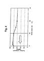
- the catalytic converters 5 of Examples 1 to 5 and Comparative Examples 1 to 3 described above were set in a testing apparatus, and an exhaust gas of 100°C was caused o flow therethrough for 30 minutes, followed by measuring generated contact pressure (MPa) of the holding and sealing material 1. The results are shown in the graph of Fig. 4.
- the assemblage of the holding and sealing material 1 is satisfactory in any case.
- the holding and sealing material 1 of this embodiment achieves the following advantages.
- the holding and sealing material 1 of this embodiment comprises a fiber aggregate mainly comprised of alumina-silica based ceramic fibers having a mullite crystal content of 10 wt% or less. Consequently, it has excellent heat resistance and a high level of resiliency against an applied compression load. Therefore, even when the holding and sealing material 1 disposed in the gap is exposed to high temperature, the generated contact pressure hardly drops. Thus, if the catalytic converter 5 is fabricated using the holding and sealing material 1, the catalytic converter 5 capable of maintaining a high level of sealing performance and carrier holding performance for a long period and having excellent durability can be obtained.
- the fiber aggregate of the holding and sealing material 1 is subjected to a needle punch treatment. Consequently, some ceramic fibers are intertwined at needle punch spots in the direction of thickness of the fiber aggregate, and thus the thickness of the fiber aggregate is reduced such that it is compressed in the direction of thickness. Therefore, bulkiness of the fiber aggregate is alleviated, thus bringing about excellent assemblage.
- the amount of organic binder required for reducing the thickness of the fiber aggregate can be reduced as it is subjected to a needle punch treatment. Therefore, extremely low-pollution characteristics can be achieved while maintaining satisfactory assemblage.
- Fibers may be intertwined by a mechanical fiber intertwinement processing method other than the needle punch treatment.
- a non-mechanical fiber intertwinement processing method utilizing water power, air power or the like may be employed.
- the form of the holding and sealing material 1 may freely be changed.
- concave and convex positional mating portions 11 and 12 may be eliminated to provide a simpler form.
- the sectional form of the catalyst carrier 3 is not limited to a circle, and for example, an elliptical or oblong form is acceptable. In this case, the sectional form of the metal shell 2 may be changed to an elliptical or oblong form in accordance therewith.
- a material other than precious metals may be carried on the catalyst carrier 3 as a catalyst.
- a cogierite carrier formed into a honeycomb shape is used, but a honeycomb porous sintered body such as silicon carbide or silicon nitride, for example, may also be used.
- the holding and sealing material 1 of the present invention may be used not only in the catalytic converter 5 for an exhaust gas cleaning apparatus, but also in, for example, a diesel particulate filter (DPF) and a catalytic converter for a fuel cell reforming apparatus.
- DPF diesel particulate filter
Priority Applications (2)
| Application Number | Priority Date | Filing Date | Title |
|---|---|---|---|
| EP06120489A EP1736644B1 (fr) | 2000-10-17 | 2001-10-17 | Matériau d'étancheité et de fixation pour un pot catalytique et procédé de fabrication correspondant |
| EP06123777A EP1757782B1 (fr) | 2000-10-17 | 2001-10-17 | Pot catalytique comprenant un matériau d'étancheité et de fixation et procédé de fabrication correspondant |
Applications Claiming Priority (3)
| Application Number | Priority Date | Filing Date | Title |
|---|---|---|---|
| JP2000316798A JP2002129455A (ja) | 2000-10-17 | 2000-10-17 | 触媒コンバータ用保持シール材及びその製造方法、触媒コンバータ |
| JP2000316798 | 2000-10-17 | ||
| PCT/JP2001/009103 WO2002033233A1 (fr) | 2000-10-17 | 2001-10-17 | Materiau etanche de fixation pour pot catalytique et procede de fabrication de celui-ci |
Related Child Applications (2)
| Application Number | Title | Priority Date | Filing Date |
|---|---|---|---|
| EP06120489A Division EP1736644B1 (fr) | 2000-10-17 | 2001-10-17 | Matériau d'étancheité et de fixation pour un pot catalytique et procédé de fabrication correspondant |
| EP06123777A Division EP1757782B1 (fr) | 2000-10-17 | 2001-10-17 | Pot catalytique comprenant un matériau d'étancheité et de fixation et procédé de fabrication correspondant |
Publications (3)
| Publication Number | Publication Date |
|---|---|
| EP1329601A1 true EP1329601A1 (fr) | 2003-07-23 |
| EP1329601A4 EP1329601A4 (fr) | 2005-02-02 |
| EP1329601B1 EP1329601B1 (fr) | 2006-11-15 |
Family
ID=18795696
Family Applications (3)
| Application Number | Title | Priority Date | Filing Date |
|---|---|---|---|
| EP06120489A Revoked EP1736644B1 (fr) | 2000-10-17 | 2001-10-17 | Matériau d'étancheité et de fixation pour un pot catalytique et procédé de fabrication correspondant |
| EP06123777A Revoked EP1757782B1 (fr) | 2000-10-17 | 2001-10-17 | Pot catalytique comprenant un matériau d'étancheité et de fixation et procédé de fabrication correspondant |
| EP01976709A Revoked EP1329601B1 (fr) | 2000-10-17 | 2001-10-17 | Materiau etanche de fixation pour pot catalytique et procede de fabrication de celui-ci |
Family Applications Before (2)
| Application Number | Title | Priority Date | Filing Date |
|---|---|---|---|
| EP06120489A Revoked EP1736644B1 (fr) | 2000-10-17 | 2001-10-17 | Matériau d'étancheité et de fixation pour un pot catalytique et procédé de fabrication correspondant |
| EP06123777A Revoked EP1757782B1 (fr) | 2000-10-17 | 2001-10-17 | Pot catalytique comprenant un matériau d'étancheité et de fixation et procédé de fabrication correspondant |
Country Status (7)
| Country | Link |
|---|---|
| US (2) | US20040052694A1 (fr) |
| EP (3) | EP1736644B1 (fr) |
| JP (1) | JP2002129455A (fr) |
| KR (6) | KR20070087127A (fr) |
| CN (1) | CN1289801C (fr) |
| DE (2) | DE60124579T2 (fr) |
| WO (1) | WO2002033233A1 (fr) |
Cited By (7)
| Publication number | Priority date | Publication date | Assignee | Title |
|---|---|---|---|---|
| EP1840346A1 (fr) * | 2006-03-31 | 2007-10-03 | Ibiden Co., Ltd. | Mat, dispositif de traitement des gaz d'échappement et procédé pour sa production |
| EP1908935A1 (fr) | 2005-12-28 | 2008-04-09 | Ibiden Co., Ltd. | Élément de retenue et d'étanchéité et procédé de fabrication d'un élément de retenue et d'étanchéité |
| EP2034152A2 (fr) * | 2001-05-25 | 2009-03-11 | Ibiden Co., Ltd. | Fibre à base d'alumine-silice, agrégation de fibres céramiques, matériau de joint de fixation et procédés de fabrication correspondants, et procédé de fabrication d'une agrégation de fibres d'alumine |
| EP2042634A1 (fr) | 2007-09-28 | 2009-04-01 | Ibiden Co., Ltd. | Matelas de fibres, appareil de traitement de gaz d'échappement et silencieux |
| EP2112342A1 (fr) * | 2008-04-23 | 2009-10-28 | Ibiden Co., Ltd. | Matériau d'étancheité et de fixation, procédé de fabrication correspondant, et système de purification de gaz d'échappement |
| EP2172625A1 (fr) * | 2008-09-25 | 2010-04-07 | Ibiden Co., Ltd. | Produit de tapis, procédé de fabrication du produit de tapis, appareil de traitement des gaz d'échappement, et appareil de pot d'échappement |
| EP2985435A4 (fr) * | 2013-04-12 | 2017-01-25 | Ibiden Co., Ltd. | Élément de joint de retenue, procédé de production d'un élément de joint de retenue et dispositif d'épuration des gaz d'échappement |
Families Citing this family (51)
| Publication number | Priority date | Publication date | Assignee | Title |
|---|---|---|---|---|
| US7572415B2 (en) * | 2000-03-22 | 2009-08-11 | Ibiden Co., Ltd. | Catalyst converter and diesel, particulate filter system |
| JP4174474B2 (ja) * | 2002-06-28 | 2008-10-29 | 電気化学工業株式会社 | 保持材用無機質短繊維集積体、その製造方法、及び保持材 |
| KR20040013835A (ko) * | 2002-08-08 | 2004-02-14 | 현대자동차주식회사 | 자동차용 촉매 컨버터의 지지체와 그 제조방법 |
| AR054074A1 (es) * | 2004-06-29 | 2007-06-06 | Unifrax Corp | Dispositivo para tratamiento de gases de escape y metodo para elaborarlo |
| JP4663341B2 (ja) * | 2005-01-25 | 2011-04-06 | イビデン株式会社 | 排気ガス浄化装置のエンドコーン部用断熱材 |
| JP4665618B2 (ja) * | 2005-06-10 | 2011-04-06 | イビデン株式会社 | 保持シール材の製造方法 |
| TWI301169B (en) * | 2005-08-10 | 2008-09-21 | Ibiden Co Ltd | Holding seal member for exhaust gas purifier, exhaust gas purification apparatus employing the same, jig for chamfering holding seal member, and method for manufacturing holding seal member |
| JP4688614B2 (ja) * | 2005-09-02 | 2011-05-25 | イビデン株式会社 | 保持シール材および排気ガス浄化装置 |
| JP4687483B2 (ja) * | 2006-02-03 | 2011-05-25 | 三菱樹脂株式会社 | モノリス保持材 |
| JP4863828B2 (ja) * | 2006-09-29 | 2012-01-25 | イビデン株式会社 | シート材、その製造方法および排気ガス処理装置 |
| JP5112029B2 (ja) * | 2007-01-26 | 2013-01-09 | イビデン株式会社 | シート材およびその製造方法、排気ガス処理装置およびその製造方法、ならびに消音装置 |
| JP5046829B2 (ja) * | 2007-09-26 | 2012-10-10 | イビデン株式会社 | 保持シール材及び保持シール材の製造方法 |
| JP2009257422A (ja) * | 2008-04-15 | 2009-11-05 | Ibiden Co Ltd | 保持シール材、及び、排ガス浄化装置 |
| KR20090117969A (ko) | 2008-04-30 | 2009-11-17 | 이비덴 가부시키가이샤 | 매트재, 매트재의 제조 방법, 소음기, 및 소음기의 제조 방법 |
| WO2010002815A2 (fr) * | 2008-06-30 | 2010-01-07 | Memc Electronic Materials, Inc. | Systèmes de réacteur à lit fluidisé et procédés pour réduire le dépôt de silicium sur des parois de réacteur |
| JP5033176B2 (ja) * | 2008-07-10 | 2012-09-26 | イビデン株式会社 | 保持シール材、排ガス浄化装置、及び、排ガス浄化装置の製造方法 |
| JP5816552B2 (ja) | 2008-08-29 | 2015-11-18 | ユニフラックス ワン リミテッド ライアビリティ カンパニー | フレキシブル縁保護剤を備えた装着マットおよび該装着マットが組込まれた排気ガス処理装置 |
| KR101719007B1 (ko) * | 2008-11-03 | 2017-04-04 | 쓰리엠 이노베이티브 프로퍼티즈 컴파니 | 장착 매트 및 이를 갖는 오염 제어 장치 |
| JP6336237B2 (ja) | 2008-11-03 | 2018-06-06 | スリーエム イノベイティブ プロパティズ カンパニー | 実装マット及び実装マットを有する汚染防止装置 |
| BRPI0923515A2 (pt) | 2008-12-15 | 2016-01-26 | Unifrax I Llc | revestimento de cobertura para estrutura em cerâmica em forma de colméia |
| RU2011126262A (ru) * | 2009-01-05 | 2013-02-10 | ЮНИФРЭКС I ЭлЭлСи | Изолирующая пластина из высокопрочных биорастворимых неорганических волокон |
| JP2010168706A (ja) * | 2009-01-26 | 2010-08-05 | Ibiden Co Ltd | マット材、排気ガス処理装置およびマット材を製造する方法 |
| JP5347595B2 (ja) * | 2009-03-12 | 2013-11-20 | 三菱樹脂株式会社 | 無機質繊維ブランケットの製造方法 |
| JP2010223083A (ja) * | 2009-03-23 | 2010-10-07 | Ibiden Co Ltd | 排ガス浄化装置、及び、排ガス浄化装置の製造方法 |
| WO2010120380A2 (fr) | 2009-04-17 | 2010-10-21 | Unifrax I Llc | Dispositif de traitement des gaz d'échappement |
| GB0906837D0 (en) | 2009-04-21 | 2009-06-03 | Saffil Automotive Ltd | Mats |
| CN102713191B (zh) * | 2009-08-10 | 2016-06-22 | 尤尼弗瑞克斯I有限责任公司 | 可变基重垫或预型件以及废气处理装置 |
| EP2464836A2 (fr) | 2009-08-14 | 2012-06-20 | Unifrax I LLC | Mat de montage pour dispositif de traitement de gaz d'échappement |
| EP2464838A1 (fr) * | 2009-08-14 | 2012-06-20 | Unifrax I LLC | Support de substrat multicouche et dispositif de traitement de gaz d'échappement |
| US8071040B2 (en) | 2009-09-23 | 2011-12-06 | Unifax I LLC | Low shear mounting mat for pollution control devices |
| CN102575552B (zh) * | 2009-09-24 | 2016-03-16 | 尤尼弗瑞克斯I有限责任公司 | 多层垫和废气处理装置 |
| JP5499644B2 (ja) * | 2009-11-06 | 2014-05-21 | 三菱樹脂株式会社 | 無機繊維成形体及びその製造方法 |
| CN102713187B (zh) | 2009-12-01 | 2016-05-04 | 萨菲尔汽车有限公司 | 安装垫 |
| CN102770630B (zh) * | 2009-12-17 | 2016-02-17 | 尤尼弗瑞克斯I有限责任公司 | 用于污染控制装置的多层安装垫 |
| KR101796329B1 (ko) * | 2009-12-17 | 2017-11-09 | 유니프랙스 아이 엘엘씨 | 배기 가스 처리 기기용 장착 매트 |
| WO2011084558A1 (fr) | 2009-12-17 | 2011-07-14 | Unifrax I Llc | Utilisation de microsphères dans une nappe de montage de dispositif de traitement des gaz d'échappement |
| KR20120110109A (ko) * | 2009-12-29 | 2012-10-09 | 엠이엠씨 일렉트로닉 머티리얼즈, 인크. | 주변 실리콘 테트라염화물을 이용하여 반응기 벽 상의 실리콘의 퇴적을 감소시키는 방법 |
| KR101818692B1 (ko) | 2010-04-13 | 2018-01-16 | 쓰리엠 이노베이티브 프로퍼티즈 캄파니 | 두꺼운 무기 섬유 웨브 및 그의 제조 및 사용 방법 |
| KR20130056868A (ko) | 2010-04-13 | 2013-05-30 | 쓰리엠 이노베이티브 프로퍼티즈 캄파니 | 무기 섬유 웨브 및 그의 제조 및 사용 방법 |
| WO2011130041A2 (fr) | 2010-04-13 | 2011-10-20 | 3M Innovative Properties Company | Procédés de fabrication de bandes fibreuses inorganiques |
| CN102834558A (zh) | 2010-04-13 | 2012-12-19 | 3M创新有限公司 | 无机纤维幅材及制备和使用方法 |
| US8765069B2 (en) | 2010-08-12 | 2014-07-01 | Unifrax I Llc | Exhaust gas treatment device |
| HUE027312T2 (en) | 2010-08-13 | 2016-10-28 | Unifrax I Llc | Mounting insert with flange flange protection and exhaust washer cleaning tool |
| US9120703B2 (en) | 2010-11-11 | 2015-09-01 | Unifrax I Llc | Mounting mat and exhaust gas treatment device |
| US9924564B2 (en) | 2010-11-11 | 2018-03-20 | Unifrax I Llc | Heated mat and exhaust gas treatment device |
| JP5971894B2 (ja) * | 2011-01-31 | 2016-08-17 | スリーエム イノベイティブ プロパティズ カンパニー | 汚染コントロール要素用保持材、その製造方法及び汚染コントロール装置 |
| US20140272363A1 (en) * | 2011-09-08 | 2014-09-18 | Mitsubishi Plastics, Inc. | Inorganic fiber molded body |
| JP5990393B2 (ja) | 2012-04-03 | 2016-09-14 | イビデン株式会社 | 保持シール材、及び、排ガス浄化装置 |
| KR20170118679A (ko) | 2015-02-24 | 2017-10-25 | 유니프랙스 아이 엘엘씨 | 내고온성 절연 매트 |
| JP2019074033A (ja) * | 2017-10-17 | 2019-05-16 | トヨタ自動車株式会社 | 電気加熱式触媒 |
| CN111714964B (zh) * | 2020-06-29 | 2021-08-17 | 浙江严牌过滤技术股份有限公司 | 一种除尘脱二噁英一体化滤料及其制备方法 |
Citations (4)
| Publication number | Priority date | Publication date | Assignee | Title |
|---|---|---|---|---|
| JPS6088162A (ja) * | 1983-10-20 | 1985-05-17 | 三菱化学株式会社 | セラミツクフアイバ−ブランケツトの製造方法 |
| JPS62231019A (ja) * | 1986-03-27 | 1987-10-09 | Ibiden Co Ltd | 高耐酸性セラミツク繊維 |
| US5290522A (en) * | 1993-01-07 | 1994-03-01 | Minnesota Mining And Manufacturing Company | Catalytic converter mounting mat |
| JPH07251018A (ja) * | 1994-03-16 | 1995-10-03 | Mitsubishi Chem Corp | オイルミスト吸着用フィルター及びその再生方法 |
Family Cites Families (27)
| Publication number | Priority date | Publication date | Assignee | Title |
|---|---|---|---|---|
| US4047965A (en) * | 1976-05-04 | 1977-09-13 | Minnesota Mining And Manufacturing Company | Non-frangible alumina-silica fibers |
| JPS60215815A (ja) * | 1984-04-10 | 1985-10-29 | Sumitomo Chem Co Ltd | 無機質繊維の製造方法 |
| CA1289315C (fr) * | 1986-09-04 | 1991-09-24 | Keiichi Kataoka | Structure spatiale de fibres refractaires et sa fabrication |
| JP2521081B2 (ja) * | 1987-03-05 | 1996-07-31 | 住友化学工業株式会社 | アルミナ質繊維の製造方法 |
| JPH0376872A (ja) * | 1989-06-08 | 1991-04-02 | Kanebo Ltd | 高純度アルミナ長繊維織物の製造方法 |
| JPH05319949A (ja) * | 1992-05-15 | 1993-12-03 | Mitsui Mining Co Ltd | アルミナ質繊維成形体の製造方法 |
| WO1994024425A1 (fr) * | 1993-04-22 | 1994-10-27 | The Carborundum Company | Matelas de montage pour structures fragiles telles que des convertisseurs catalytiques |
| US5866079A (en) * | 1993-09-03 | 1999-02-02 | Ngk Insulators, Ltd. | Ceramic honeycomb catalytic converter |
| JP3282362B2 (ja) * | 1994-04-15 | 2002-05-13 | 三菱化学株式会社 | 排ガス浄化装置用把持材 |
| US5523059A (en) * | 1995-06-30 | 1996-06-04 | Minnesota Mining And Manufacturing Company | Intumescent sheet material with glass fibers |
| JPH1182006A (ja) * | 1997-09-12 | 1999-03-26 | Denki Kagaku Kogyo Kk | 断熱シール材及びその用途 |
| JP4652553B2 (ja) * | 2000-11-10 | 2011-03-16 | イビデン株式会社 | 触媒コンバータ及びその製造方法 |
| EP1418317A4 (fr) * | 2001-05-25 | 2008-03-05 | Ibiden Co Ltd | Fibre a base d'alumine-silice, fibre ceramique, complexe de fibres ceramiques, materiau d'etancheite, procede de production de celui-ci et procede de production de complexe de fibres d'alumine |
| JP4730495B2 (ja) * | 2001-05-25 | 2011-07-20 | イビデン株式会社 | 触媒コンバータ用保持シール材及びその製造方法、触媒コンバータ |
| JP4665618B2 (ja) * | 2005-06-10 | 2011-04-06 | イビデン株式会社 | 保持シール材の製造方法 |
| JP4959206B2 (ja) * | 2006-03-02 | 2012-06-20 | イビデン株式会社 | 耐熱シートおよび排気ガス浄化装置 |
| JP2007292040A (ja) * | 2006-03-31 | 2007-11-08 | Ibiden Co Ltd | シート材、排気ガス処理装置およびその製造方法 |
| JP4802048B2 (ja) * | 2006-06-16 | 2011-10-26 | イビデン株式会社 | 保持シール材、排ガス処理装置およびその製造方法 |
| JP2008045521A (ja) * | 2006-08-21 | 2008-02-28 | Ibiden Co Ltd | 保持シール材および排気ガス処理装置 |
| JP2008051004A (ja) * | 2006-08-24 | 2008-03-06 | Ibiden Co Ltd | 保持シール材および排気ガス処理装置 |
| EP1953357B1 (fr) * | 2007-01-26 | 2009-08-26 | Ibiden Co., Ltd. | Mat de support et son procédé de fabrication, appareil de traitement de gaz d'échappement et son procédé de fabrication et dispositif silencieux |
| JP5014113B2 (ja) * | 2007-01-26 | 2012-08-29 | イビデン株式会社 | シート材、その製造方法、排気ガス処理装置および消音装置 |
| JP5046829B2 (ja) * | 2007-09-26 | 2012-10-10 | イビデン株式会社 | 保持シール材及び保持シール材の製造方法 |
| JP4959499B2 (ja) * | 2007-09-28 | 2012-06-20 | イビデン株式会社 | マット材、排気ガス処理装置および消音装置 |
| JP2009085093A (ja) * | 2007-09-28 | 2009-04-23 | Ibiden Co Ltd | マット材、マット材を作製する方法、排気ガス処理装置および消音装置 |
| JP2009085091A (ja) * | 2007-09-28 | 2009-04-23 | Ibiden Co Ltd | マット材、排気ガス処理装置および消音装置 |
| JP5014070B2 (ja) * | 2007-11-06 | 2012-08-29 | イビデン株式会社 | マット材および排気ガス処理装置 |
-
2000
- 2000-10-17 JP JP2000316798A patent/JP2002129455A/ja active Pending
-
2001
- 2001-10-17 DE DE60124579T patent/DE60124579T2/de not_active Expired - Lifetime
- 2001-10-17 EP EP06120489A patent/EP1736644B1/fr not_active Revoked
- 2001-10-17 KR KR1020077016312A patent/KR20070087127A/ko active Search and Examination
- 2001-10-17 KR KR1020027007670A patent/KR20020068056A/ko active Search and Examination
- 2001-10-17 KR KR1020107001040A patent/KR20100018086A/ko active Application Filing
- 2001-10-17 EP EP06123777A patent/EP1757782B1/fr not_active Revoked
- 2001-10-17 EP EP01976709A patent/EP1329601B1/fr not_active Revoked
- 2001-10-17 US US10/399,036 patent/US20040052694A1/en not_active Abandoned
- 2001-10-17 KR KR1020087014778A patent/KR20080065705A/ko active Search and Examination
- 2001-10-17 WO PCT/JP2001/009103 patent/WO2002033233A1/fr active IP Right Grant
- 2001-10-17 DE DE20122864U patent/DE20122864U1/de not_active Expired - Lifetime
- 2001-10-17 CN CNB018031374A patent/CN1289801C/zh not_active Expired - Lifetime
- 2001-10-17 KR KR1020107028367A patent/KR101153763B1/ko active IP Right Grant
- 2001-10-17 KR KR1020117021072A patent/KR101232957B1/ko active IP Right Grant
-
2007
- 2007-08-03 US US11/833,804 patent/US20080312071A1/en not_active Abandoned
Patent Citations (4)
| Publication number | Priority date | Publication date | Assignee | Title |
|---|---|---|---|---|
| JPS6088162A (ja) * | 1983-10-20 | 1985-05-17 | 三菱化学株式会社 | セラミツクフアイバ−ブランケツトの製造方法 |
| JPS62231019A (ja) * | 1986-03-27 | 1987-10-09 | Ibiden Co Ltd | 高耐酸性セラミツク繊維 |
| US5290522A (en) * | 1993-01-07 | 1994-03-01 | Minnesota Mining And Manufacturing Company | Catalytic converter mounting mat |
| JPH07251018A (ja) * | 1994-03-16 | 1995-10-03 | Mitsubishi Chem Corp | オイルミスト吸着用フィルター及びその再生方法 |
Non-Patent Citations (3)
| Title |
|---|
| PATENT ABSTRACTS OF JAPAN vol. 0121, no. 03 (C-485), 5 April 1988 (1988-04-05) & JP 62 231019 A (IBIDEN CO LTD), 9 October 1987 (1987-10-09) * |
| PATENT ABSTRACTS OF JAPAN vol. 1996, no. 02, 29 February 1996 (1996-02-29) & JP 7 251018 A (MITSUBISHI CHEM CORP), 3 October 1995 (1995-10-03) * |
| See also references of WO0233233A1 * |
Cited By (23)
| Publication number | Priority date | Publication date | Assignee | Title |
|---|---|---|---|---|
| EP2042699A3 (fr) * | 2001-05-25 | 2012-10-10 | Ibiden Co., Ltd. | Fibre à base d'alumine-silice, fibre céramique, agrégation de fibres céramiques, matériau de joint de fixation et procédés de fabrication correspondants, et procédé de fabrication d'une agrégation de fibres d'alumine |
| EP2034152A2 (fr) * | 2001-05-25 | 2009-03-11 | Ibiden Co., Ltd. | Fibre à base d'alumine-silice, agrégation de fibres céramiques, matériau de joint de fixation et procédés de fabrication correspondants, et procédé de fabrication d'une agrégation de fibres d'alumine |
| US8790581B2 (en) | 2001-05-25 | 2014-07-29 | Ibiden Co., Ltd. | Alumina-silica-based fiber, ceramic fiber, ceramic fiber complex, retaining seal material, production method thereof, and alumina fiber complex production method |
| EP2034153A2 (fr) * | 2001-05-25 | 2009-03-11 | Ibiden Co., Ltd. | Fibre à base d'alumine-silice, fibre céramique, agrégation de fibres céramiques, matériau de joint de fixation et procédés de fabrication correspondants, et procédé de fabrication d'une agrégation de fibres d'alumine |
| EP2037093A2 (fr) * | 2001-05-25 | 2009-03-18 | Ibiden Co., Ltd. | Fibre à base d'alumine-silice, fibre céramique, agrégation de fibres céramiques, matériau de joint de fixation et procédés de fabrication correspondants, et procédé de fabrication d'une agrégation de fibres d'alumine |
| EP2042699A2 (fr) * | 2001-05-25 | 2009-04-01 | Ibiden Co., Ltd. | Fibre à base d'alumine-silice, fibre céramique, agrégation de fibres céramiques, matériau de joint de fixation et procédés de fabrication correspondants, et procédé de fabrication d'une agrégation de fibres d'alumine |
| US8540941B2 (en) | 2001-05-25 | 2013-09-24 | Ibiden Co., Ltd. | Alumina-silica-based fiber, ceramic fiber, ceramic fiber complex, retaining seal material, production method thereof, and alumina fiber complex production method |
| US8303901B2 (en) | 2001-05-25 | 2012-11-06 | Ibiden Co., Ltd. | Alumina-silica-based fiber, ceramic fiber, ceramic fiber complex, retaining seal material, production method thereof, and alumina fiber complex production method |
| EP2246538A2 (fr) * | 2001-05-25 | 2010-11-03 | Ibiden Co., Ltd. | Fibre a base d'alumine-silice, fibre céramique, complexe de fibres céramiques, matériau d'étanchéité, procédé de production de celui-ci et procédé de production de complexe de fibres d'alumine |
| EP2267283B1 (fr) | 2005-12-28 | 2018-11-14 | Ibiden Co., Ltd. | Procédé de fabrication d'un élément de retenue et d'étanchéité |
| EP1908935B1 (fr) * | 2005-12-28 | 2014-10-29 | Ibiden Co., Ltd. | Procédé de fabrication d'un élément de retenue et d'étanchéité pour organe de purification de gaz d'échappement |
| EP1908935A1 (fr) | 2005-12-28 | 2008-04-09 | Ibiden Co., Ltd. | Élément de retenue et d'étanchéité et procédé de fabrication d'un élément de retenue et d'étanchéité |
| EP2933454A1 (fr) * | 2005-12-28 | 2015-10-21 | Ibiden Co., Ltd. | Élément de scellage de fixation pour corps de purification de gaz d'échappement, purificateur de gaz d'échappement et procédé de fabrication d'élément de scellage de fixation |
| CN102619599A (zh) * | 2005-12-28 | 2012-08-01 | 揖斐电株式会社 | 密封保持元件、废气处理装置及密封保持元件的制造方法 |
| EP2267283A1 (fr) * | 2005-12-28 | 2010-12-29 | Ibiden Co., Ltd. | Élément de retenue et d'étanchéité et procédé de fabrication d'un élément de retenue et d'étanchéité |
| EP1840346A1 (fr) * | 2006-03-31 | 2007-10-03 | Ibiden Co., Ltd. | Mat, dispositif de traitement des gaz d'échappement et procédé pour sa production |
| EP2042634A1 (fr) | 2007-09-28 | 2009-04-01 | Ibiden Co., Ltd. | Matelas de fibres, appareil de traitement de gaz d'échappement et silencieux |
| US8038953B2 (en) | 2007-09-28 | 2011-10-18 | Ibiden Co., Ltd. | Mat material, exhaust gas treating apparatus, and muffler |
| EP2112342A1 (fr) * | 2008-04-23 | 2009-10-28 | Ibiden Co., Ltd. | Matériau d'étancheité et de fixation, procédé de fabrication correspondant, et système de purification de gaz d'échappement |
| US8268256B2 (en) | 2008-04-23 | 2012-09-18 | Ibiden Co., Ltd. | Holding sealing material, method for manufacturing holding sealing material, and exhaust gas purifying apparatus |
| US8231835B2 (en) | 2008-09-25 | 2012-07-31 | Ibiden Co., Ltd. | Mat product, manufacturing method of the mat product, exhaust gas treating apparatus, and muffler apparatus |
| EP2172625A1 (fr) * | 2008-09-25 | 2010-04-07 | Ibiden Co., Ltd. | Produit de tapis, procédé de fabrication du produit de tapis, appareil de traitement des gaz d'échappement, et appareil de pot d'échappement |
| EP2985435A4 (fr) * | 2013-04-12 | 2017-01-25 | Ibiden Co., Ltd. | Élément de joint de retenue, procédé de production d'un élément de joint de retenue et dispositif d'épuration des gaz d'échappement |
Also Published As
| Publication number | Publication date |
|---|---|
| EP1757782A2 (fr) | 2007-02-28 |
| EP1757782B1 (fr) | 2011-08-03 |
| KR101232957B1 (ko) | 2013-02-13 |
| EP1736644B1 (fr) | 2011-07-20 |
| KR101153763B1 (ko) | 2012-06-13 |
| EP1757782A3 (fr) | 2007-03-07 |
| KR20080065705A (ko) | 2008-07-14 |
| EP1329601B1 (fr) | 2006-11-15 |
| KR20070087127A (ko) | 2007-08-27 |
| DE60124579D1 (de) | 2006-12-28 |
| EP1736644A1 (fr) | 2006-12-27 |
| KR20110003403A (ko) | 2011-01-11 |
| KR20020068056A (ko) | 2002-08-24 |
| WO2002033233A1 (fr) | 2002-04-25 |
| DE60124579T2 (de) | 2007-10-25 |
| KR20100018086A (ko) | 2010-02-16 |
| CN1392921A (zh) | 2003-01-22 |
| US20080312071A1 (en) | 2008-12-18 |
| CN1289801C (zh) | 2006-12-13 |
| KR20110113776A (ko) | 2011-10-18 |
| JP2002129455A (ja) | 2002-05-09 |
| DE20122864U1 (de) | 2008-08-28 |
| EP1329601A4 (fr) | 2005-02-02 |
| US20040052694A1 (en) | 2004-03-18 |
Similar Documents
| Publication | Publication Date | Title |
|---|---|---|
| EP1329601B1 (fr) | Materiau etanche de fixation pour pot catalytique et procede de fabrication de celui-ci | |
| JP4557976B2 (ja) | 汚染コントロール要素の保持材及び汚染コントロール装置 | |
| JP4730495B2 (ja) | 触媒コンバータ用保持シール材及びその製造方法、触媒コンバータ | |
| EP1736220A1 (fr) | Structure en nid d'abeilles | |
| US20090049831A1 (en) | Pollution control element-mounting member and pollution control device | |
| US20040022699A1 (en) | Catalytic converter and method for manufacture thereof | |
| US8580207B2 (en) | Holding sealing material, exhaust gas purifying apparatus, and method for manufacturing holding sealing material | |
| JP2002206421A (ja) | 触媒コンバータ用保持シール材、セラミック繊維及びセラミック繊維の製造方法 | |
| WO2013111428A1 (fr) | Matériau de support pour dispositif de traitement de gaz, dispositif de traitement de gaz et procédés de production associés | |
| EP1342888B1 (fr) | Convertisseur catalytique et procede de fabrication de celui-ci | |
| JP2011231774A (ja) | 触媒コンバータ用保持シール材の製造方法 | |
| JP4730497B2 (ja) | 触媒コンバータ用保持シール材及びその製造方法 | |
| JP4993816B2 (ja) | アルミナーシリカ系繊維及びその製造方法、触媒コンバータ用保持シール材 | |
| JP4730496B2 (ja) | 触媒コンバータ用保持シール材及びその製造方法、セラミック繊維集合体、セラミック繊維 | |
| JP2011169325A (ja) | 触媒コンバータ用保持シール材及びその製造方法、セラミック繊維集合体、セラミック繊維 | |
| JP4671536B2 (ja) | 触媒コンバータ用保持シール材及びその製造方法 | |
| JP2013155750A (ja) | 触媒コンバータ用保持シール材 | |
| JP4663885B2 (ja) | アルミナ−シリカ系繊維の製造方法 | |
| JP2002221031A (ja) | 触媒コンバータ用保持シール材及びその製造方法、セラミック繊維集合体 | |
| JP2015078702A (ja) | 触媒コンバータ用保持シール材の製造方法 | |
| JP2011169326A (ja) | 触媒コンバータ用保持シール材及び触媒コンバータ |
Legal Events
| Date | Code | Title | Description |
|---|---|---|---|
| PUAI | Public reference made under article 153(3) epc to a published international application that has entered the european phase |
Free format text: ORIGINAL CODE: 0009012 |
|
| 17P | Request for examination filed |
Effective date: 20030423 |
|
| AK | Designated contracting states |
Designated state(s): AT BE CH CY DE DK ES FI FR GB GR IE IT LI LU MC NL PT SE TR |
|
| A4 | Supplementary search report drawn up and despatched |
Effective date: 20041221 |
|
| RIC1 | Information provided on ipc code assigned before grant |
Ipc: 7D 04H 1/46 B Ipc: 7F 01N 3/28 A Ipc: 7D 04H 1/42 B |
|
| 17Q | First examination report despatched |
Effective date: 20050301 |
|
| GRAP | Despatch of communication of intention to grant a patent |
Free format text: ORIGINAL CODE: EPIDOSNIGR1 |
|
| RBV | Designated contracting states (corrected) |
Designated state(s): DE FR GB IT |
|
| GRAS | Grant fee paid |
Free format text: ORIGINAL CODE: EPIDOSNIGR3 |
|
| GRAA | (expected) grant |
Free format text: ORIGINAL CODE: 0009210 |
|
| AK | Designated contracting states |
Kind code of ref document: B1 Designated state(s): DE FR GB IT |
|
| PG25 | Lapsed in a contracting state [announced via postgrant information from national office to epo] |
Ref country code: IT Free format text: LAPSE BECAUSE OF FAILURE TO SUBMIT A TRANSLATION OF THE DESCRIPTION OR TO PAY THE FEE WITHIN THE PRESCRIBED TIME-LIMIT;WARNING: LAPSES OF ITALIAN PATENTS WITH EFFECTIVE DATE BEFORE 2007 MAY HAVE OCCURRED AT ANY TIME BEFORE 2007. THE CORRECT EFFECTIVE DATE MAY BE DIFFERENT FROM THE ONE RECORDED. Effective date: 20061115 |
|
| REG | Reference to a national code |
Ref country code: GB Ref legal event code: FG4D |
|
| REF | Corresponds to: |
Ref document number: 60124579 Country of ref document: DE Date of ref document: 20061228 Kind code of ref document: P |
|
| ET | Fr: translation filed | ||
| PLBI | Opposition filed |
Free format text: ORIGINAL CODE: 0009260 |
|
| PLAX | Notice of opposition and request to file observation + time limit sent |
Free format text: ORIGINAL CODE: EPIDOSNOBS2 |
|
| 26 | Opposition filed |
Opponent name: 3M INNOVATIVE PROPERTIES COMPANY Effective date: 20070814 |
|
| PLAF | Information modified related to communication of a notice of opposition and request to file observations + time limit |
Free format text: ORIGINAL CODE: EPIDOSCOBS2 |
|
| PLBB | Reply of patent proprietor to notice(s) of opposition received |
Free format text: ORIGINAL CODE: EPIDOSNOBS3 |
|
| PLAB | Opposition data, opponent's data or that of the opponent's representative modified |
Free format text: ORIGINAL CODE: 0009299OPPO |
|
| PLAB | Opposition data, opponent's data or that of the opponent's representative modified |
Free format text: ORIGINAL CODE: 0009299OPPO |
|
| R26 | Opposition filed (corrected) |
Opponent name: 3M INNOVATIVE PROPERTIES COMPANY Effective date: 20070814 |
|
| PLAB | Opposition data, opponent's data or that of the opponent's representative modified |
Free format text: ORIGINAL CODE: 0009299OPPO |
|
| RDAF | Communication despatched that patent is revoked |
Free format text: ORIGINAL CODE: EPIDOSNREV1 |
|
| APBM | Appeal reference recorded |
Free format text: ORIGINAL CODE: EPIDOSNREFNO |
|
| APBP | Date of receipt of notice of appeal recorded |
Free format text: ORIGINAL CODE: EPIDOSNNOA2O |
|
| APAH | Appeal reference modified |
Free format text: ORIGINAL CODE: EPIDOSCREFNO |
|
| APBQ | Date of receipt of statement of grounds of appeal recorded |
Free format text: ORIGINAL CODE: EPIDOSNNOA3O |
|
| PLAB | Opposition data, opponent's data or that of the opponent's representative modified |
Free format text: ORIGINAL CODE: 0009299OPPO |
|
| R26 | Opposition filed (corrected) |
Opponent name: 3M INNOVATIVE PROPERTIES COMPANY Effective date: 20070814 |
|
| PGFP | Annual fee paid to national office [announced via postgrant information from national office to epo] |
Ref country code: FR Payment date: 20121018 Year of fee payment: 12 |
|
| PGFP | Annual fee paid to national office [announced via postgrant information from national office to epo] |
Ref country code: GB Payment date: 20121017 Year of fee payment: 12 |
|
| APBU | Appeal procedure closed |
Free format text: ORIGINAL CODE: EPIDOSNNOA9O |
|
| REG | Reference to a national code |
Ref country code: DE Ref legal event code: R064 Ref document number: 60124579 Country of ref document: DE Ref country code: DE Ref legal event code: R103 Ref document number: 60124579 Country of ref document: DE |
|
| PGFP | Annual fee paid to national office [announced via postgrant information from national office to epo] |
Ref country code: DE Payment date: 20131009 Year of fee payment: 13 |
|
| RDAG | Patent revoked |
Free format text: ORIGINAL CODE: 0009271 |
|
| STAA | Information on the status of an ep patent application or granted ep patent |
Free format text: STATUS: PATENT REVOKED |
|
| 27W | Patent revoked |
Effective date: 20130715 |
|
| GBPR | Gb: patent revoked under art. 102 of the ep convention designating the uk as contracting state |
Effective date: 20130715 |
|
| REG | Reference to a national code |
Ref country code: DE Ref legal event code: R107 Ref document number: 60124579 Country of ref document: DE Effective date: 20140424 |