EP1322864B1 - Flügel aus kunststoff für eine flügelzellen-vakuumpumpe - Google Patents
Flügel aus kunststoff für eine flügelzellen-vakuumpumpe Download PDFInfo
- Publication number
- EP1322864B1 EP1322864B1 EP01982127A EP01982127A EP1322864B1 EP 1322864 B1 EP1322864 B1 EP 1322864B1 EP 01982127 A EP01982127 A EP 01982127A EP 01982127 A EP01982127 A EP 01982127A EP 1322864 B1 EP1322864 B1 EP 1322864B1
- Authority
- EP
- European Patent Office
- Prior art keywords
- vane
- end part
- wing
- vacuum pump
- plastic
- Prior art date
- Legal status (The legal status is an assumption and is not a legal conclusion. Google has not performed a legal analysis and makes no representation as to the accuracy of the status listed.)
- Expired - Lifetime
Links
- 239000004033 plastic Substances 0.000 title claims description 8
- 229920003023 plastic Polymers 0.000 title claims description 8
- 239000000463 material Substances 0.000 claims description 17
- 238000001746 injection moulding Methods 0.000 claims description 7
- 238000000137 annealing Methods 0.000 claims description 2
- 239000011248 coating agent Substances 0.000 claims description 2
- 238000000576 coating method Methods 0.000 claims description 2
- 238000000465 moulding Methods 0.000 claims description 2
- 229920001169 thermoplastic Polymers 0.000 claims description 2
- 229920001187 thermosetting polymer Polymers 0.000 claims description 2
- 239000004416 thermosoftening plastic Substances 0.000 claims description 2
- 238000004519 manufacturing process Methods 0.000 description 4
- 238000011161 development Methods 0.000 description 2
- 230000018109 developmental process Effects 0.000 description 2
- 238000002347 injection Methods 0.000 description 2
- 239000007924 injection Substances 0.000 description 2
- 229920006260 polyaryletherketone Polymers 0.000 description 2
- 238000001721 transfer moulding Methods 0.000 description 2
- 241000446313 Lamella Species 0.000 description 1
- ISWSIDIOOBJBQZ-UHFFFAOYSA-N Phenol Chemical compound OC1=CC=CC=C1 ISWSIDIOOBJBQZ-UHFFFAOYSA-N 0.000 description 1
- 238000004026 adhesive bonding Methods 0.000 description 1
- 150000001875 compounds Chemical class 0.000 description 1
- 238000000748 compression moulding Methods 0.000 description 1
- 238000004132 cross linking Methods 0.000 description 1
- 230000001419 dependent effect Effects 0.000 description 1
- 239000000945 filler Substances 0.000 description 1
- 239000003365 glass fiber Substances 0.000 description 1
- 238000010438 heat treatment Methods 0.000 description 1
- 238000000034 method Methods 0.000 description 1
- 238000009740 moulding (composite fabrication) Methods 0.000 description 1
- 229920003986 novolac Polymers 0.000 description 1
- 238000007789 sealing Methods 0.000 description 1
- IHQKEDIOMGYHEB-UHFFFAOYSA-M sodium dimethylarsinate Chemical class [Na+].C[As](C)([O-])=O IHQKEDIOMGYHEB-UHFFFAOYSA-M 0.000 description 1
- 239000012815 thermoplastic material Substances 0.000 description 1
- 238000003466 welding Methods 0.000 description 1
Images
Classifications
-
- F—MECHANICAL ENGINEERING; LIGHTING; HEATING; WEAPONS; BLASTING
- F01—MACHINES OR ENGINES IN GENERAL; ENGINE PLANTS IN GENERAL; STEAM ENGINES
- F01C—ROTARY-PISTON OR OSCILLATING-PISTON MACHINES OR ENGINES
- F01C21/00—Component parts, details or accessories not provided for in groups F01C1/00 - F01C20/00
- F01C21/08—Rotary pistons
- F01C21/0809—Construction of vanes or vane holders
- F01C21/0881—Construction of vanes or vane holders the vanes consisting of two or more parts
-
- F—MECHANICAL ENGINEERING; LIGHTING; HEATING; WEAPONS; BLASTING
- F04—POSITIVE - DISPLACEMENT MACHINES FOR LIQUIDS; PUMPS FOR LIQUIDS OR ELASTIC FLUIDS
- F04C—ROTARY-PISTON, OR OSCILLATING-PISTON, POSITIVE-DISPLACEMENT MACHINES FOR LIQUIDS; ROTARY-PISTON, OR OSCILLATING-PISTON, POSITIVE-DISPLACEMENT PUMPS
- F04C18/00—Rotary-piston pumps specially adapted for elastic fluids
- F04C18/30—Rotary-piston pumps specially adapted for elastic fluids having the characteristics covered by two or more of groups F04C18/02, F04C18/08, F04C18/22, F04C18/24, F04C18/48, or having the characteristics covered by one of these groups together with some other type of movement between co-operating members
- F04C18/34—Rotary-piston pumps specially adapted for elastic fluids having the characteristics covered by two or more of groups F04C18/02, F04C18/08, F04C18/22, F04C18/24, F04C18/48, or having the characteristics covered by one of these groups together with some other type of movement between co-operating members having the movement defined in group F04C18/08 or F04C18/22 and relative reciprocation between the co-operating members
- F04C18/344—Rotary-piston pumps specially adapted for elastic fluids having the characteristics covered by two or more of groups F04C18/02, F04C18/08, F04C18/22, F04C18/24, F04C18/48, or having the characteristics covered by one of these groups together with some other type of movement between co-operating members having the movement defined in group F04C18/08 or F04C18/22 and relative reciprocation between the co-operating members with vanes reciprocating with respect to the inner member
- F04C18/3441—Rotary-piston pumps specially adapted for elastic fluids having the characteristics covered by two or more of groups F04C18/02, F04C18/08, F04C18/22, F04C18/24, F04C18/48, or having the characteristics covered by one of these groups together with some other type of movement between co-operating members having the movement defined in group F04C18/08 or F04C18/22 and relative reciprocation between the co-operating members with vanes reciprocating with respect to the inner member the inner and outer member being in contact along one line or continuous surface substantially parallel to the axis of rotation
- F04C18/3442—Rotary-piston pumps specially adapted for elastic fluids having the characteristics covered by two or more of groups F04C18/02, F04C18/08, F04C18/22, F04C18/24, F04C18/48, or having the characteristics covered by one of these groups together with some other type of movement between co-operating members having the movement defined in group F04C18/08 or F04C18/22 and relative reciprocation between the co-operating members with vanes reciprocating with respect to the inner member the inner and outer member being in contact along one line or continuous surface substantially parallel to the axis of rotation the surfaces of the inner and outer member, forming the inlet and outlet opening
Definitions
- the invention is based on a wing made of plastic for a vane vacuum pump, according to the genus of Patent claim 1.
- the wing according to the invention with the features of Patent claim 1 is advantageous in that, firstly a mounting of separately produced items is eliminated on the other hand, the injection mold the final shape of the wing determined reproducibly with relatively tight tolerances.
- claim 2 embodiment is a Structure of the wing specified, at first the body the wing by injection molding, transfer molding or Forming presses and subsequently produced in the same or a separate injection mold the end-side part of the wing is manufactured.
- the development of the invention according to claim 3 is insofar advantageous, as one hand, the dimensional accuracy of the wing by a reduced influence of material shrinkage on end part is improved, on the other hand, the cost of the wing can be kept low when the Material of the end-side part is expensive.
- the measure marked in claim 4 provides an im During the manufacture of the grand piano in a simple way producible connection of the parts of the wing, especially if with the materials used for the Body and the end part of the wing no Material limit can be achieved.
- heat treatment of Body of the wing will be an increase in strength of the wing by the maximum achievable, spatial Degree of crosslinking of the molecular structures and a constancy of the Wing geometry due to stress reduction in the material structure and avoiding the Nachschwindens achieved.
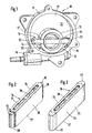
- FIG. 1 shows a Spatial representation of a vane vacuum pump with a single wing
- Figure 2 as a spatial image of the body of Wing
- Figure 3 also as a room image with two end parts completed wings.
- a vane-type vacuum pump 10 shown in FIG. 1 has a reproduced without cover pump housing 11 with a Interior 12, in which a drivable rotor 13 eccentric is arranged.
- the rotor 13 is with a transverse Slot 14 for longitudinally movable guide of a plastic existing wing 15 provided.
- the wing 15 attacks slidable and sealing on a shell side Inner wall 16, on an end wall 17 and not on drawn lid of the pump housing 11 at.
- the Pump housing 11 further includes an intake manifold 18 a coat side opening into the interior 12 Inlet opening 19 and the end face an outlet opening 20th on.
- the intake manifold 18 is connected to a not shown Vacuum brake booster of a vehicle brake system connected.
- the operation of the vane vacuum pump 10 is known, so there is no further Explanation is needed.
- the lamellar wing 15 is made Plastic. Its shown in Figure 2 of the drawing Body 21 is made of a duroplastic. He is out a glass fiber reinforced phenol novolak molding compound or a material with comparable properties Injection molding, transfer molding or compression molding. This material is characterized by high mechanical and dynamic load capacity and oil resistance. His Material properties are in the temperature range of -40 ° C to + 150 ° C largely constant. The setting behavior of Material is very high over the life of the vacuum pump 10 low. The material properties of said thermoset can be improved by annealing the body 21 for several hours become.
- the wing 15 has molded end portions 22 and 23rd made of a high temperature resistant thermoplastic such as polyaryletherketone (PEEK) or a material with consist of comparable properties. This if necessary through a specially composed filler combination modified plastic has a high wear resistance and a low friction coefficient.
- the End-side parts 22 and 23 are by a Injection molding with the body 21 of the wing 15th united.
- the body 21, with opposite its broad sides 24, 25 and its narrow sides 26, 27 stepped recessed end portions 28, 29 is provided (see Figure 2), taken in a tool mold and with the mentioned thermoplastic material to that in Figure 3 form supplemented.
- the plastics used for the body 21 and the end portions 22, 23 of the wing 15 no or one are inadequate previously described embodiment of the wing 15 measures to achieve a positive connection between the mentioned Parts and the body of the wing 15 is provided.
- the end portions 28 and 29 of the body 21 have three longitudinal, straight grooves 30 half to three-quarter circular cross-section, which of the Material of the end-side parts 22 and 23 at Injection molding process are completed. This way will a lifting or releasing the end-side parts 22, 23 from Body 21 of the wing 15 prevented.
- Wing 15 In deviation from the above-described manufacturing process of Wing 15 can temper the body 21 without damage for the end-side parts 22, 23 after their union with done to the body.
- the manufacturing process can also be applied to vane vacuum pumps Find application where wings with only a single end sliding coating can be used.
Landscapes
- Engineering & Computer Science (AREA)
- Mechanical Engineering (AREA)
- General Engineering & Computer Science (AREA)
- Rotary Pumps (AREA)
- Applications Or Details Of Rotary Compressors (AREA)
- Injection Moulding Of Plastics Or The Like (AREA)
- Structures Of Non-Positive Displacement Pumps (AREA)
Description
Claims (5)
- Flügel (15) aus Kunststoff für eine Flügelzellen-Vakuumpumpe (10), der in einem Rotor (13) längs geführt ist und mit wenigstens einem endseitigen Teil (22, 23) gleitbeweglich an der mantelseitigen Innenwand (16) eines Pumpengehäuses (11) angreift, wobei der Körper (21) des Flügels (15) und sein endseitiger Teil (22, 23) aus unterschiedlichen Werkstoffen bestehen, von denen der Werkstoff des endseitigen Teils (22, 23) einen hohen Verschleißwiderstand hat, dadurch gekennzeichnet, dass der Körper (21) des Flügels (15) aus einem Duroplast und sein endseitiger Teil (22, 23) aus einem Thermoplast bestehen, welche durch einen Spritzgießvorgang miteinander vereinigt sind.
- Flügel nach Anspruch 1, dadurch gekennzeichnet, dass nach dem Formen des Körpers (21) des Flügels (15) der endseitige Teil (22, 23) in einem Spritzgießvorgang hergestellt ist.
- Flügel nach Anspruch 1 oder 2, dadurch gekennzeichnet, dass der endseitige Teil (22, 23) des Flügels (15) als Schicht geringer Dicke ausgebildet ist.
- Flügel nach Anspruch 1 oder 2, dadurch gekennzeichnet, dass der Körper (21) des Flügels (15) und der endseitige Teil (22, 23) durch Formschluss miteinander verbunden sind.
- Flügel nach Anspruch 1 oder 2, dadurch gekennzeichnet, dass der Körper (21) des Flügels (15) vor oder nach dem Spritzgießen des endseitigen Teils (22, 23) einer Temperung unterzogen ist.
Applications Claiming Priority (3)
| Application Number | Priority Date | Filing Date | Title |
|---|---|---|---|
| DE10046697 | 2000-09-21 | ||
| DE10046697A DE10046697A1 (de) | 2000-09-21 | 2000-09-21 | Flügel aus Kunststoff für eine Flügelzellen-Vakuumpumpe |
| PCT/DE2001/003598 WO2002025113A1 (de) | 2000-09-21 | 2001-09-19 | Flügel aus kunststoff für eine flügelzellen-vakuumpumpe |
Publications (2)
| Publication Number | Publication Date |
|---|---|
| EP1322864A1 EP1322864A1 (de) | 2003-07-02 |
| EP1322864B1 true EP1322864B1 (de) | 2004-03-10 |
Family
ID=7657030
Family Applications (1)
| Application Number | Title | Priority Date | Filing Date |
|---|---|---|---|
| EP01982127A Expired - Lifetime EP1322864B1 (de) | 2000-09-21 | 2001-09-19 | Flügel aus kunststoff für eine flügelzellen-vakuumpumpe |
Country Status (8)
| Country | Link |
|---|---|
| US (1) | US6655937B2 (de) |
| EP (1) | EP1322864B1 (de) |
| JP (1) | JP2004509289A (de) |
| CN (1) | CN1230625C (de) |
| DE (2) | DE10046697A1 (de) |
| ES (1) | ES2217196T3 (de) |
| HU (1) | HU222979B1 (de) |
| WO (1) | WO2002025113A1 (de) |
Cited By (1)
| Publication number | Priority date | Publication date | Assignee | Title |
|---|---|---|---|---|
| DE102005056270B3 (de) * | 2005-11-14 | 2007-03-01 | Joma-Hydromechanic Gmbh | Rotorpumpe |
Families Citing this family (31)
| Publication number | Priority date | Publication date | Assignee | Title |
|---|---|---|---|---|
| EP1327778A3 (de) * | 2000-03-15 | 2003-07-23 | Joma-Hydromechanic GmbH | Flügelzellenpumpe |
| DE20118896U1 (de) * | 2001-11-20 | 2003-03-27 | Joh. Winklhofer & Söhne GmbH und Co KG, 81369 München | Kettenrad |
| DE10307040A1 (de) * | 2003-02-20 | 2004-09-16 | Luk Automobiltechnik Gmbh & Co. Kg | Vakuumpumpe |
| WO2004074687A2 (de) * | 2003-02-20 | 2004-09-02 | Luk Automobiltechnik Gmbh & Co. Kg | Vakuumpumpe mit einem kunststoffflügel |
| EP1471255B1 (de) * | 2003-04-24 | 2005-07-20 | Joma-Hydromechanic GmbH | Flügelzellenpumpe |
| DE202004010821U1 (de) * | 2003-07-23 | 2004-12-23 | The Boc Group Plc, Windlesham | Vakuumpumpenbauteil |
| DE102004034919B3 (de) * | 2004-07-09 | 2005-12-01 | Joma-Hydromechanic Gmbh | Einflügelvakuumpumpe |
| DE102004034921B9 (de) * | 2004-07-09 | 2006-04-27 | Joma-Hydromechanic Gmbh | Einflügelvakuumpumpe |
| DE102004034925B3 (de) * | 2004-07-09 | 2006-02-16 | Joma-Hydromechanic Gmbh | Einflügelvakuumpumpe |
| DE102004053521A1 (de) * | 2004-10-29 | 2006-05-11 | Joma-Hydromechanic Gmbh | Flügel für eine Rotorpumpe |
| DE102005050001A1 (de) * | 2005-10-13 | 2007-04-19 | Joma-Hydromechanic Gmbh | Rotorpumpe |
| DE502006008822D1 (de) * | 2005-10-13 | 2011-03-10 | Joma Polytec Gmbh | Rotorpumpe und flügel für eine rotorpumpe |
| DE102006012889A1 (de) * | 2005-11-14 | 2007-05-16 | Joma Hydromechanic Gmbh | Vakuumpumpe |
| DE102006011913A1 (de) * | 2006-03-09 | 2007-09-13 | Joma-Hydromechanic Gmbh | Vakuumpumpe |
| EP1948936A1 (de) | 2005-11-14 | 2008-07-30 | Joma-Hydromechanic GmbH | Vakuumpumpe |
| DE102005058129A1 (de) * | 2005-11-30 | 2007-05-31 | Joma-Hydromechanic Gmbh | Vakuumpumpe |
| ITTO20060673A1 (it) * | 2006-09-21 | 2008-03-22 | Vhit Spa | Pompa rotativa a palette |
| EP2173971B1 (de) * | 2007-07-03 | 2016-12-21 | O.M.P. Officine Mazzocco Pagnoni S.r.l. | Vakuumpumpe für einen kraftfahrzeugmotor |
| DE102008019440A1 (de) * | 2008-04-17 | 2009-10-22 | FRÖTEK Kunststofftechnik GmbH | Flügel einer Flügelzellenpumpe oder eines Flügelzellenkompressors |
| DE102008057227A1 (de) | 2008-11-04 | 2010-05-12 | Joma-Hydromechanic Gmbh | Flügel für eine Einflügelvakuumpumpe |
| DE102010051610B4 (de) | 2009-11-24 | 2023-10-26 | Hanon Systems Efp Deutschland Gmbh | Vakuumpumpe |
| DE102012002759A1 (de) | 2012-02-11 | 2013-08-14 | Volkswagen Aktiengesellschaft | Hybridantrieb und Pumpe mit einem solchen Hybridantrieb |
| CN102536822B (zh) * | 2012-02-14 | 2016-06-08 | 无锡明治泵业有限公司 | 滚柱滑片真空泵 |
| CN103850937B (zh) * | 2012-11-30 | 2016-08-24 | 上海华培动力科技有限公司 | 一种辅助车用制动系统的负压装置 |
| DE102013204503B4 (de) * | 2013-03-14 | 2017-03-30 | Schwäbische Hüttenwerke Automotive GmbH | Flügelzellenpumpe mit Flügel mit Oberflächenstruktur |
| DE102015213098B4 (de) * | 2015-07-13 | 2017-05-04 | Joma-Polytec Gmbh | Flügel für eine Flügelzellenpumpe und Flügelzellenpumpe |
| CN105020141A (zh) * | 2015-07-24 | 2015-11-04 | 裕克施乐塑料制品(太仓)有限公司 | 一种端部可变形的真空泵叶片及真空泵 |
| CN105156324B (zh) * | 2015-09-11 | 2018-09-04 | 裕克施乐塑料制品(太仓)有限公司 | 一种新型塑料真空泵叶片及真空泵 |
| CN105570129A (zh) * | 2016-02-25 | 2016-05-11 | 上海华培动力科技有限公司 | 用于机械真空泵的叶片结构 |
| JP6967954B2 (ja) * | 2017-12-05 | 2021-11-17 | 東京エレクトロン株式会社 | 排気装置、処理装置及び排気方法 |
| CN113048059A (zh) * | 2021-04-06 | 2021-06-29 | 湖南腾智机电有限责任公司 | 一种机械真空泵的组合式旋片 |
Family Cites Families (18)
| Publication number | Priority date | Publication date | Assignee | Title |
|---|---|---|---|---|
| DE7503397U (de) | 1975-05-28 | Peters C Ag | Lamelle für Zellenverdichter | |
| GB1426126A (en) | 1973-02-16 | 1976-02-25 | Komiya S | Movable vane type compressor |
| DE2421906C2 (de) * | 1974-05-07 | 1984-04-26 | UNUS dei F.lli Rossato V. & S., S.N.C., Padua | Drehkolbenluftpumpe |
| JPS54161611U (de) * | 1978-05-02 | 1979-11-12 | ||
| JPS569693A (en) * | 1979-07-04 | 1981-01-31 | Kanebo Ltd | Vane for rotary pump and its manufacture |
| JPS5652594A (en) * | 1979-10-08 | 1981-05-11 | Taiho Kogyo Co Ltd | Vane for vane pump |
| JPS59153995A (ja) * | 1983-02-21 | 1984-09-01 | Mitsubishi Electric Corp | ポンプ装置 |
| DE3318281A1 (de) * | 1983-05-17 | 1984-11-29 | Bernhard 1000 Berlin Lohff | Verbrennungsmotor |
| JPS6331275U (de) * | 1986-08-15 | 1988-02-29 | ||
| JPS63105287A (ja) * | 1986-10-20 | 1988-05-10 | Tokico Ltd | 空気圧縮機用弁装置 |
| JPH0460192A (ja) * | 1990-06-29 | 1992-02-26 | Toshiba Corp | コンプレッサー |
| JPH04325226A (ja) * | 1991-04-24 | 1992-11-13 | Onishi Raito Kogyosho:Kk | 軸受製造方法および軸受 |
| JPH07269468A (ja) * | 1994-03-31 | 1995-10-17 | Tokico Ltd | ベーンポンプ用翼弁 |
| JPH0951958A (ja) * | 1995-08-14 | 1997-02-25 | Nippon Kikai Kogyo Kk | 消防ポンプ呼水用の真空ポンプ |
| US5651930A (en) * | 1995-10-25 | 1997-07-29 | Zexel Usa Corporation | Composite fiber rotor vane |
| DE19901419C2 (de) * | 1999-01-18 | 2002-11-07 | Jose Poch-Parramon | Kunststoffmischung |
| US6364646B1 (en) * | 1999-05-27 | 2002-04-02 | Kevin R. Kirtley | Rotary vane pump with continuous carbon fiber reinforced polyetheretherketone (peek) vanes |
| EP1327778A3 (de) * | 2000-03-15 | 2003-07-23 | Joma-Hydromechanic GmbH | Flügelzellenpumpe |
-
2000
- 2000-09-21 DE DE10046697A patent/DE10046697A1/de not_active Withdrawn
-
2001
- 2001-09-19 ES ES01982127T patent/ES2217196T3/es not_active Expired - Lifetime
- 2001-09-19 HU HU0203934A patent/HU222979B1/hu not_active IP Right Cessation
- 2001-09-19 CN CNB018028276A patent/CN1230625C/zh not_active Expired - Lifetime
- 2001-09-19 JP JP2002528683A patent/JP2004509289A/ja active Pending
- 2001-09-19 EP EP01982127A patent/EP1322864B1/de not_active Expired - Lifetime
- 2001-09-19 US US10/130,362 patent/US6655937B2/en not_active Expired - Lifetime
- 2001-09-19 DE DE50101676T patent/DE50101676D1/de not_active Expired - Lifetime
- 2001-09-19 WO PCT/DE2001/003598 patent/WO2002025113A1/de not_active Ceased
Cited By (1)
| Publication number | Priority date | Publication date | Assignee | Title |
|---|---|---|---|---|
| DE102005056270B3 (de) * | 2005-11-14 | 2007-03-01 | Joma-Hydromechanic Gmbh | Rotorpumpe |
Also Published As
| Publication number | Publication date |
|---|---|
| ES2217196T3 (es) | 2004-11-01 |
| HUP0203934A2 (en) | 2003-03-28 |
| JP2004509289A (ja) | 2004-03-25 |
| CN1404555A (zh) | 2003-03-19 |
| DE10046697A1 (de) | 2002-04-11 |
| EP1322864A1 (de) | 2003-07-02 |
| CN1230625C (zh) | 2005-12-07 |
| US20030053924A1 (en) | 2003-03-20 |
| HU222979B1 (hu) | 2004-01-28 |
| DE50101676D1 (de) | 2004-04-15 |
| US6655937B2 (en) | 2003-12-02 |
| WO2002025113A1 (de) | 2002-03-28 |
Similar Documents
| Publication | Publication Date | Title |
|---|---|---|
| EP1322864A1 (de) | Flügel aus kunststoff für eine flügelzellen-vakuumpumpe | |
| DE2046486C3 (de) | Schaufelrad für Lüfter | |
| DE69109458T2 (de) | Ein mehrschichtiges Rohr aus Kunststoff und Verfahren zu dessen Herstellung. | |
| DE3312231A1 (de) | Hohlkoerper aus kunststoffen | |
| DE102004045142A1 (de) | Zylinderkopfdichtung | |
| DE102013005705A1 (de) | Fluiddichte Kontaktdurchführung | |
| DE3405456A1 (de) | Verbindung zweier bauteile, insbesondere zweier kunststoffhalbschalen | |
| WO2004074687A2 (de) | Vakuumpumpe mit einem kunststoffflügel | |
| DE102008000274A1 (de) | Elektronische Drosselvorrichtung und Verfahren zu deren Herstellung | |
| DE102007005216A1 (de) | Vakuumpumpe | |
| DE10307040A1 (de) | Vakuumpumpe | |
| DE102012013538A1 (de) | Verfahren und Vorrichtung zur Herstellung von Sandwichelementen | |
| WO2024141140A1 (de) | Ventil zur verwendung in einem fahrzeug-kühlkreislauf sowie verfahren zur herstellung eines derartigen ventils | |
| DE10326207A1 (de) | Verfahren zur Herstellung eines Zylinders für einen Zweitaktmotor | |
| EP1838563A1 (de) | UNTERDRUCKBREMSKRAFTVERSTÄRkKER MIT EINEM VERBESSERTEN ANSCHLUSSELEMENT ZUR VERBINDUNG MIT EINER UNTERDRUCKQUELLE | |
| DE102020123517B4 (de) | Laufrad für eine Zentrifugalflüssigkeitspumpe sowie Zentrifugalflüssigkeitspumpe aufweisend das Laufrad und Kraftfahrzeug aufweisend eine solche Zentrifugalfluidpumpe | |
| DE102013019837A1 (de) | Werkzeug zum Herstellen eines Bauteils, insbesondere eines Kunststoffbauteils | |
| WO2008003279A2 (de) | Vakuumpumpe, spritzgiesswerkzeug für das pumpengehäuse, herstellungsverfahren des pumpengehauses und herstellungsverfahren eines pumpengehäuses mit zwei in einem arbeitsgang hergestellten dichtungen | |
| DE102018208702A1 (de) | Verkleidungsteil, Verfahren und Vorrichtung zum Herstellen eines Verkleidungsteils | |
| DE102009048135A1 (de) | Elektrohydraulische Steuervorrichtung | |
| DE19618381A1 (de) | Druckleitende Verbindungsanordnung | |
| EP4588738A1 (de) | Relaisventil für eine druckluftanlage eines fahrzeugs | |
| DE102014015400A1 (de) | Leitungsanordnung für einen Kraftwagen, insbesondere einen Personenkraftwagen | |
| WO2007065600A1 (de) | Verfahren zur herstellung eines wenigstens zwei oberflächenzonen aufweisenden ausstattungsteils für ein kraftfahrzeug, formwerkzeug und ausstattungsteil für ein kraftfahrzeug | |
| DE102013111388A1 (de) | Halbzeug zur Herstellung eines Hybridbauteils |
Legal Events
| Date | Code | Title | Description |
|---|---|---|---|
| REG | Reference to a national code |
Ref country code: GB Ref legal event code: FG4D Free format text: NOT ENGLISH |
|
| PUAI | Public reference made under article 153(3) epc to a published international application that has entered the european phase |
Free format text: ORIGINAL CODE: 0009012 |
|
| 17P | Request for examination filed |
Effective date: 20030422 |
|
| AK | Designated contracting states |
Designated state(s): AT BE CH CY DE DK ES FI FR GB GR IE IT LI LU MC NL PT SE TR |
|
| GRAP | Despatch of communication of intention to grant a patent |
Free format text: ORIGINAL CODE: EPIDOSNIGR1 |
|
| RIN1 | Information on inventor provided before grant (corrected) |
Inventor name: PILONE, MONICA Inventor name: CADEDDU, LEONARDO Inventor name: HASERT, WOLFRAM |
|
| GRAS | Grant fee paid |
Free format text: ORIGINAL CODE: EPIDOSNIGR3 |
|
| GRAA | (expected) grant |
Free format text: ORIGINAL CODE: 0009210 |
|
| AK | Designated contracting states |
Kind code of ref document: B1 Designated state(s): DE ES FR GB IT |
|
| REG | Reference to a national code |
Ref country code: IE Ref legal event code: FG4D Free format text: GERMAN |
|
| REF | Corresponds to: |
Ref document number: 50101676 Country of ref document: DE Date of ref document: 20040415 Kind code of ref document: P |
|
| GBT | Gb: translation of ep patent filed (gb section 77(6)(a)/1977) |
Effective date: 20040726 |
|
| REG | Reference to a national code |
Ref country code: IE Ref legal event code: FD4D |
|
| REG | Reference to a national code |
Ref country code: ES Ref legal event code: FG2A Ref document number: 2217196 Country of ref document: ES Kind code of ref document: T3 |
|
| ET | Fr: translation filed | ||
| PLBE | No opposition filed within time limit |
Free format text: ORIGINAL CODE: 0009261 |
|
| STAA | Information on the status of an ep patent application or granted ep patent |
Free format text: STATUS: NO OPPOSITION FILED WITHIN TIME LIMIT |
|
| 26N | No opposition filed |
Effective date: 20041213 |
|
| REG | Reference to a national code |
Ref country code: FR Ref legal event code: PLFP Year of fee payment: 16 |
|
| REG | Reference to a national code |
Ref country code: FR Ref legal event code: PLFP Year of fee payment: 17 |
|
| PGFP | Annual fee paid to national office [announced via postgrant information from national office to epo] |
Ref country code: ES Payment date: 20171003 Year of fee payment: 17 |
|
| REG | Reference to a national code |
Ref country code: FR Ref legal event code: PLFP Year of fee payment: 18 |
|
| PGFP | Annual fee paid to national office [announced via postgrant information from national office to epo] |
Ref country code: FR Payment date: 20190923 Year of fee payment: 19 |
|
| REG | Reference to a national code |
Ref country code: ES Ref legal event code: FD2A Effective date: 20191031 |
|
| PGFP | Annual fee paid to national office [announced via postgrant information from national office to epo] |
Ref country code: GB Payment date: 20190924 Year of fee payment: 19 |
|
| PG25 | Lapsed in a contracting state [announced via postgrant information from national office to epo] |
Ref country code: ES Free format text: LAPSE BECAUSE OF NON-PAYMENT OF DUE FEES Effective date: 20180920 |
|
| REG | Reference to a national code |
Ref country code: DE Ref legal event code: R084 Ref document number: 50101676 Country of ref document: DE |
|
| PGFP | Annual fee paid to national office [announced via postgrant information from national office to epo] |
Ref country code: IT Payment date: 20200930 Year of fee payment: 20 Ref country code: DE Payment date: 20201121 Year of fee payment: 20 |
|
| GBPC | Gb: european patent ceased through non-payment of renewal fee |
Effective date: 20200919 |
|
| PG25 | Lapsed in a contracting state [announced via postgrant information from national office to epo] |
Ref country code: FR Free format text: LAPSE BECAUSE OF NON-PAYMENT OF DUE FEES Effective date: 20200930 |
|
| PG25 | Lapsed in a contracting state [announced via postgrant information from national office to epo] |
Ref country code: GB Free format text: LAPSE BECAUSE OF NON-PAYMENT OF DUE FEES Effective date: 20200919 |
|
| REG | Reference to a national code |
Ref country code: DE Ref legal event code: R071 Ref document number: 50101676 Country of ref document: DE |