EP1316702A2 - Appareil permettant d'agir sur la recirculation d'egr d'un moteur à combustion - Google Patents
Appareil permettant d'agir sur la recirculation d'egr d'un moteur à combustion Download PDFInfo
- Publication number
- EP1316702A2 EP1316702A2 EP02025737A EP02025737A EP1316702A2 EP 1316702 A2 EP1316702 A2 EP 1316702A2 EP 02025737 A EP02025737 A EP 02025737A EP 02025737 A EP02025737 A EP 02025737A EP 1316702 A2 EP1316702 A2 EP 1316702A2
- Authority
- EP
- European Patent Office
- Prior art keywords
- egr
- valve
- opening
- intake throttle
- throttle valve
- Prior art date
- Legal status (The legal status is an assumption and is not a legal conclusion. Google has not performed a legal analysis and makes no representation as to the accuracy of the status listed.)
- Granted
Links
Images


Classifications
-
- F—MECHANICAL ENGINEERING; LIGHTING; HEATING; WEAPONS; BLASTING
- F02—COMBUSTION ENGINES; HOT-GAS OR COMBUSTION-PRODUCT ENGINE PLANTS
- F02D—CONTROLLING COMBUSTION ENGINES
- F02D41/00—Electrical control of supply of combustible mixture or its constituents
- F02D41/0025—Controlling engines characterised by use of non-liquid fuels, pluralities of fuels, or non-fuel substances added to the combustible mixtures
- F02D41/0047—Controlling exhaust gas recirculation [EGR]
- F02D41/005—Controlling exhaust gas recirculation [EGR] according to engine operating conditions
- F02D41/0052—Feedback control of engine parameters, e.g. for control of air/fuel ratio or intake air amount
-
- F—MECHANICAL ENGINEERING; LIGHTING; HEATING; WEAPONS; BLASTING
- F02—COMBUSTION ENGINES; HOT-GAS OR COMBUSTION-PRODUCT ENGINE PLANTS
- F02B—INTERNAL-COMBUSTION PISTON ENGINES; COMBUSTION ENGINES IN GENERAL
- F02B23/00—Other engines characterised by special shape or construction of combustion chambers to improve operation
- F02B23/02—Other engines characterised by special shape or construction of combustion chambers to improve operation with compression ignition
- F02B23/06—Other engines characterised by special shape or construction of combustion chambers to improve operation with compression ignition the combustion space being arranged in working piston
- F02B23/0672—Omega-piston bowl, i.e. the combustion space having a central projection pointing towards the cylinder head and the surrounding wall being inclined towards the cylinder center axis
-
- F—MECHANICAL ENGINEERING; LIGHTING; HEATING; WEAPONS; BLASTING
- F02—COMBUSTION ENGINES; HOT-GAS OR COMBUSTION-PRODUCT ENGINE PLANTS
- F02D—CONTROLLING COMBUSTION ENGINES
- F02D35/00—Controlling engines, dependent on conditions exterior or interior to engines, not otherwise provided for
- F02D35/0007—Controlling engines, dependent on conditions exterior or interior to engines, not otherwise provided for using electrical feedback
-
- F—MECHANICAL ENGINEERING; LIGHTING; HEATING; WEAPONS; BLASTING
- F02—COMBUSTION ENGINES; HOT-GAS OR COMBUSTION-PRODUCT ENGINE PLANTS
- F02B—INTERNAL-COMBUSTION PISTON ENGINES; COMBUSTION ENGINES IN GENERAL
- F02B29/00—Engines characterised by provision for charging or scavenging not provided for in groups F02B25/00, F02B27/00 or F02B33/00 - F02B39/00; Details thereof
- F02B29/04—Cooling of air intake supply
- F02B29/0406—Layout of the intake air cooling or coolant circuit
-
- F—MECHANICAL ENGINEERING; LIGHTING; HEATING; WEAPONS; BLASTING
- F02—COMBUSTION ENGINES; HOT-GAS OR COMBUSTION-PRODUCT ENGINE PLANTS
- F02B—INTERNAL-COMBUSTION PISTON ENGINES; COMBUSTION ENGINES IN GENERAL
- F02B3/00—Engines characterised by air compression and subsequent fuel addition
- F02B3/06—Engines characterised by air compression and subsequent fuel addition with compression ignition
-
- F—MECHANICAL ENGINEERING; LIGHTING; HEATING; WEAPONS; BLASTING
- F02—COMBUSTION ENGINES; HOT-GAS OR COMBUSTION-PRODUCT ENGINE PLANTS
- F02D—CONTROLLING COMBUSTION ENGINES
- F02D41/00—Electrical control of supply of combustible mixture or its constituents
- F02D41/0002—Controlling intake air
- F02D2041/0017—Controlling intake air by simultaneous control of throttle and exhaust gas recirculation
-
- F—MECHANICAL ENGINEERING; LIGHTING; HEATING; WEAPONS; BLASTING
- F02—COMBUSTION ENGINES; HOT-GAS OR COMBUSTION-PRODUCT ENGINE PLANTS
- F02D—CONTROLLING COMBUSTION ENGINES
- F02D41/00—Electrical control of supply of combustible mixture or its constituents
- F02D41/20—Output circuits, e.g. for controlling currents in command coils
- F02D2041/202—Output circuits, e.g. for controlling currents in command coils characterised by the control of the circuit
- F02D2041/2024—Output circuits, e.g. for controlling currents in command coils characterised by the control of the circuit the control switching a load after time-on and time-off pulses
- F02D2041/2027—Control of the current by pulse width modulation or duty cycle control
-
- F—MECHANICAL ENGINEERING; LIGHTING; HEATING; WEAPONS; BLASTING
- F02—COMBUSTION ENGINES; HOT-GAS OR COMBUSTION-PRODUCT ENGINE PLANTS
- F02D—CONTROLLING COMBUSTION ENGINES
- F02D2200/00—Input parameters for engine control
- F02D2200/02—Input parameters for engine control the parameters being related to the engine
- F02D2200/04—Engine intake system parameters
- F02D2200/0404—Throttle position
-
- F—MECHANICAL ENGINEERING; LIGHTING; HEATING; WEAPONS; BLASTING
- F02—COMBUSTION ENGINES; HOT-GAS OR COMBUSTION-PRODUCT ENGINE PLANTS
- F02D—CONTROLLING COMBUSTION ENGINES
- F02D41/00—Electrical control of supply of combustible mixture or its constituents
- F02D41/02—Circuit arrangements for generating control signals
- F02D41/18—Circuit arrangements for generating control signals by measuring intake air flow
- F02D41/187—Circuit arrangements for generating control signals by measuring intake air flow using a hot wire flow sensor
-
- F—MECHANICAL ENGINEERING; LIGHTING; HEATING; WEAPONS; BLASTING
- F02—COMBUSTION ENGINES; HOT-GAS OR COMBUSTION-PRODUCT ENGINE PLANTS
- F02M—SUPPLYING COMBUSTION ENGINES IN GENERAL WITH COMBUSTIBLE MIXTURES OR CONSTITUENTS THEREOF
- F02M26/00—Engine-pertinent apparatus for adding exhaust gases to combustion-air, main fuel or fuel-air mixture, e.g. by exhaust gas recirculation [EGR] systems
- F02M26/02—EGR systems specially adapted for supercharged engines
- F02M26/04—EGR systems specially adapted for supercharged engines with a single turbocharger
- F02M26/05—High pressure loops, i.e. wherein recirculated exhaust gas is taken out from the exhaust system upstream of the turbine and reintroduced into the intake system downstream of the compressor
-
- F—MECHANICAL ENGINEERING; LIGHTING; HEATING; WEAPONS; BLASTING
- F02—COMBUSTION ENGINES; HOT-GAS OR COMBUSTION-PRODUCT ENGINE PLANTS
- F02M—SUPPLYING COMBUSTION ENGINES IN GENERAL WITH COMBUSTIBLE MIXTURES OR CONSTITUENTS THEREOF
- F02M26/00—Engine-pertinent apparatus for adding exhaust gases to combustion-air, main fuel or fuel-air mixture, e.g. by exhaust gas recirculation [EGR] systems
- F02M26/02—EGR systems specially adapted for supercharged engines
- F02M26/09—Constructional details, e.g. structural combinations of EGR systems and supercharger systems; Arrangement of the EGR and supercharger systems with respect to the engine
- F02M26/10—Constructional details, e.g. structural combinations of EGR systems and supercharger systems; Arrangement of the EGR and supercharger systems with respect to the engine having means to increase the pressure difference between the exhaust and intake system, e.g. venturis, variable geometry turbines, check valves using pressure pulsations or throttles in the air intake or exhaust system
-
- F—MECHANICAL ENGINEERING; LIGHTING; HEATING; WEAPONS; BLASTING
- F02—COMBUSTION ENGINES; HOT-GAS OR COMBUSTION-PRODUCT ENGINE PLANTS
- F02M—SUPPLYING COMBUSTION ENGINES IN GENERAL WITH COMBUSTIBLE MIXTURES OR CONSTITUENTS THEREOF
- F02M26/00—Engine-pertinent apparatus for adding exhaust gases to combustion-air, main fuel or fuel-air mixture, e.g. by exhaust gas recirculation [EGR] systems
- F02M26/13—Arrangement or layout of EGR passages, e.g. in relation to specific engine parts or for incorporation of accessories
- F02M26/22—Arrangement or layout of EGR passages, e.g. in relation to specific engine parts or for incorporation of accessories with coolers in the recirculation passage
- F02M26/23—Layout, e.g. schematics
-
- F—MECHANICAL ENGINEERING; LIGHTING; HEATING; WEAPONS; BLASTING
- F02—COMBUSTION ENGINES; HOT-GAS OR COMBUSTION-PRODUCT ENGINE PLANTS
- F02M—SUPPLYING COMBUSTION ENGINES IN GENERAL WITH COMBUSTIBLE MIXTURES OR CONSTITUENTS THEREOF
- F02M26/00—Engine-pertinent apparatus for adding exhaust gases to combustion-air, main fuel or fuel-air mixture, e.g. by exhaust gas recirculation [EGR] systems
- F02M26/52—Systems for actuating EGR valves
- F02M26/53—Systems for actuating EGR valves using electric actuators, e.g. solenoids
-
- Y—GENERAL TAGGING OF NEW TECHNOLOGICAL DEVELOPMENTS; GENERAL TAGGING OF CROSS-SECTIONAL TECHNOLOGIES SPANNING OVER SEVERAL SECTIONS OF THE IPC; TECHNICAL SUBJECTS COVERED BY FORMER USPC CROSS-REFERENCE ART COLLECTIONS [XRACs] AND DIGESTS
- Y02—TECHNOLOGIES OR APPLICATIONS FOR MITIGATION OR ADAPTATION AGAINST CLIMATE CHANGE
- Y02T—CLIMATE CHANGE MITIGATION TECHNOLOGIES RELATED TO TRANSPORTATION
- Y02T10/00—Road transport of goods or passengers
- Y02T10/10—Internal combustion engine [ICE] based vehicles
- Y02T10/12—Improving ICE efficiencies
-
- Y—GENERAL TAGGING OF NEW TECHNOLOGICAL DEVELOPMENTS; GENERAL TAGGING OF CROSS-SECTIONAL TECHNOLOGIES SPANNING OVER SEVERAL SECTIONS OF THE IPC; TECHNICAL SUBJECTS COVERED BY FORMER USPC CROSS-REFERENCE ART COLLECTIONS [XRACs] AND DIGESTS
- Y02—TECHNOLOGIES OR APPLICATIONS FOR MITIGATION OR ADAPTATION AGAINST CLIMATE CHANGE
- Y02T—CLIMATE CHANGE MITIGATION TECHNOLOGIES RELATED TO TRANSPORTATION
- Y02T10/00—Road transport of goods or passengers
- Y02T10/10—Internal combustion engine [ICE] based vehicles
- Y02T10/40—Engine management systems
Definitions
- the present invention relates to an EGR (exhaust gas recirculation) control apparatus for an internal combustion engine, and more particularly to controlling the EGR volume (or EGR rate; same below) by means of an EGR valve and an intake throttle valve.
- EGR exhaust gas recirculation
- the EGR control in diesel engines controls the EGR volume by controlling the opening of the EGR valve such that the actual EGR volume reaches the target EGR volume corresponding to the running condition of the engine. If the EGR volume is insufficient even when the EGR valve is fully opened, an intake throttle valve is further provided, the intake is throttled in the insufficient region (primarily the low load region of the engine), and the EGR volume is increased.
- the value of the intake air volume (new air volume) is generally used as an alternative value to the value of the EGR volume. More specifically, the total intake air volume entering the cylinder is the sum of the intake air volume comprising the new air and the EGR gas volume (EGR volume), and the total in cylinder intake air volume is substantially constant if the air intake mass or the like. (e.g., boost pressure) is fixed; therefore, controlling the intake air volume makes it possible to control the EGR volume.
- both valve When feedback control is conducted for both the EGR valve and the intake throttle valve so that a match with the target EGR volume (or target intake air volume) is established, neither valve can be controlled with correlation or coordination, the valves end up operating arbitrarily, and proper control cannot be achieved. More specifically, the openings of both valves cannot be uniquely determined in relation to a single target value, and control that differs from intended control (for example, both valves close simultaneously) occurs. Therefore, it is believed that feedback control must be provided to one of the valves, and open-loop control must be provided to the other valve.
- Figs. 8 and 9 display examples of conventional control. Displayed herein are examples in which feedback control is provided to the EGR valve, and open-loop control is provided to the intake throttle valve.
- the value of the EGR volume replaces the value of the intake air (new air) mass, namely, the air mass volume.
- Duty control is provided to the EGR valve and intake throttle valve, and the opening is changed in accordance with the duty (duty value) of the given duty signal.
- Fig. 8 illustrates control of the EGR valve
- Fig. 9 illustrates control of the intake throttle valve.
- the actual engine speed Ne, fuel injection volume Q, and air mass volume Ga are first read (step 801).
- the target air mass volume Gat is calculated in accordance with the map M81 on the basis of the engine speed Ne and fuel injection volume Q (step 802).
- the map M81 predetermines the relationship between the engine speed Ne or fuel injection volume Q and the air-fuel ratio A/F, and the target air mass volume is calculated from the obtained air-fuel ratio A/F.
- the drawing displays only the calculation map M82 of the proportional gain GP. Based on this map M82, a high proportional gain GP is incrementally assigned as the deviation ⁇ Ga increases.
- C is a specific constant.
- the actual air mass volume is brought closer to the target air mass volume, and, as a result, the actual EGR volume is brought closer to the target EGR volume by repeating this process flow at specific time intervals.
- the actual engine speed Ne and fuel injection volume Q are read (step 901), and, based on these values, the target valve duty D assigned to the intake throttle valve from the map M91 is calculated (step 902). As the engine speed Ne or fuel injection volume Q increases, the value of the target valve duty D increases on the open side. In this way, the duty assigned to the intake throttle valve is determined without any consideration given to the actual value.
- the invention of claim 1 is an EGR control apparatus for an internal combustion engine comprising an EGR valve provided to an EGR duct for connecting the intake duct and exhaust duct of an engine; an intake throttle valve provided to the intake duct; feedback control means for providing feedback control to the EGR valve and intake throttle valve such that the actual EGR volume approximates the target EGR volume corresponding to the running condition of the engine; and limiting means for limiting the operable opening ranges of the EGR valve and intake throttle valve in accordance with the target EGR volume.
- the invention of claim 2 is the invention according to claim 1 in which the limiting means imposes restrictions so that the openings of the EGR valve and intake throttle valve are variable within specific opening ranges when the target EGR volume falls within a specific range.
- the invention of claim 3 is the invention according to claims 1 or 2 in which the limiting means limits the operable opening range of either the EGR valve or the intake throttle valve in accordance with the target opening of the other valve obtained by the feedback.
- the invention of claim 4 is the invention according to claim 3 in which the limiting means determines the operable opening ranges of the EGR valve and intake throttle valve in accordance with specific maps.
- the invention of claim 5 is the invention according to claims 3 or 4 in which the limiting means imposes restrictions so that the EGR valve remains fully opened when the target opening of the intake throttle valve is equal to or less than a first opening, the EGR valve is operable from the point where the valve is fully opened to the opening where the valve closes as the target opening increases when the target opening is greater than the first opening but is equal to or less than a second opening, and the EGR valve is operable from the point where the valve is fully opened to the point where the valve is fully closed when the target opening is greater than the second opening.
- the limiting means also imposes restrictions so that the intake throttle valve remains fully opened when the target opening of the EGR valve is equal to or less than a third opening, the intake throttle valve is operable from the point where the intake throttle valve is fully opened to the opening where the intake throttle valve closes as the target opening increases when the target opening is greater than the third opening but is equal to or less than a fourth opening, and the intake throttle valve is operable from the point where the valve is fully opened to the point where the valve is fully closed when the target opening is greater than the fourth opening.
- the invention of claim 6 is the invention according to any of claims 1 to 5 in which the value of the EGR volume is replaced with the value of the intake air volume entering the intake duct, a means of detecting the intake air volume is provided in the intake duct for the purpose of detecting the actual intake air volume, and the feedback control means determines the target opening of the EGR valve and intake throttle valve on the basis of the deviation between the actual intake air volume and the target intake air volume.
- the invention of claim 7 is the invention according to any of claims 1 to 6 in which duty control is provided to the EGR valve and intake throttle valve, and the openings of the EGR valve and intake throttle valve are replaced with the duty values of the duty signals assigned thereto.
- the invention of claim 8 comprises an EGR valve provided to an EGR duct for connecting the intake duct and exhaust duct of an engine; an intake throttle valve and air mass sensor provided in the intake duct; feedback control means for providing feedback control to the EGR valve and intake throttle valve such that the actual air mass volume detected with the air mass sensor approximates a predetermined target air mass volume in accordance with the running condition of the engine; and valve opening limiting means wherein the range of the duty assigned to either the EGR valve or the intake throttle valve is limited by means of a target duty that corresponds to the other valve and is obtained by the feedback, and restrictions are imposed whereby the openings of the EGR valve and intake throttle valve can be varied within specific ranges with regard to specific regions in which the valves are fully opened.
- the invention of claim 9 is an EGR control method for an internal combustion engine in which both an EGR valve provided in an EGR duct communicating with the intake duct of the engine and an intake throttle valve provided in the intake duct undergo feedback control such that the actual EGR volume approximates the target EGR volume corresponding to the running condition of the engine, wherein the operable opening range of one of the EGR valve and the intake throttle valve is mutually limited in accordance with the target opening of the other valve obtained by the feedback.
- the invention of claim 10 is the invention according to claim 9 in which the openings of the EGR valve and intake throttle valve can be varied within specific ranges when the target EGR volume falls within a specific range.
- Fig. 1 is a system diagram depicting an engine that pertains to an embodiment of the present invention
- Fig. 2 is a graph depicting basic information about EGR control provided by the present apparatus
- Fig. 3 is a graph depicting specific details of EGR control provided by the present apparatus
- Figs. 4a-4c are opening limit maps for the EGR valve and intake throttle valve
- Fig. 5 is a flowchart depicting details of EGR control provided by the present apparatus
- Fig. 6 is a conventional example of the effect verification results relating to EGR control
- Fig. 7 is a present embodiment example of the effect verification results relating to EGR control
- Fig. 8 is a flowchart depicting details of conventional EGR valve feedback control.
- Fig. 9 is a flowchart depicting details of conventional open-loop control for the intake throttle valve.
- Fig. 1 depicts an internal combustion engine pertaining to the present embodiment.
- the internal combustion engine is a diesel engine, and in particular, the present embodiment is a common rail diesel engine comprising a common rail fuel injection apparatus. This engine is designed for use in automobiles.
- the body comprises a cylinder 2, a cylinder head 3, a piston 4, an intake port 5, an exhaust port 6, an intake valve 7, an exhaust valve 8, and an injector 9, which acts as a fuel injection valve.
- a combustion chamber 10 is formed inside the cylinder 2 and fuel is injected from the injector 9 to the combustion chamber 10.
- a cavity 11 is formed on top of the piston 4, and this cavity 11 is part of the combustion chamber 10.
- the cavity 11 is in the shape of a re-entrant combustion chamber raised in the central portion of the bottom.
- the fuel injected from the injector 9 constantly reaches the cavity 11.
- the injector 9 is positioned substantially concentrically with the cylinder 2 and is used to inject fuel from multiple injection holes simultaneously in a radial pattern. The angle formed by each portion of fuel mist L and the cylinder core C is remains the same at all times.
- the intake port 5 is connected to an intake tube 12, and the exhaust port 6 is connected to an exhaust tube 13.
- the intake port 5 and intake tube 12 form an intake duct, and the exhaust port 6 and exhaust tube 13 form an exhaust duct.
- This engine is provided with a turbocharger 14, which turbocharges the intake air by using the exhaust energy.
- 15 is a turbine and 16 is a compressor.
- a means of detecting the intake air volume is provided upstream from the compressor 16 for the purpose of detecting the actual intake air volume (new air volume) in the intake duct.
- the means of detecting the intake air volume comprises an air mass sensor 17 for the purpose of detecting the mass of the intake air.
- An air cleaner 28 is provided upstream from the air mass sensor 17.
- An intercooler 18 is provided downstream from the compressor 16 for the purpose of cooling the intake air.
- the present embodiment is a turbocharged engine; however, the present invention may also be effective in a natural intake air engine without a turbocharger.
- the EGR apparatus 19 comprises an EGR tube 20 for connecting the intake tube 12 and the exhaust tube 13 (this forms the EGR duct), an EGR valve 21 provided in the midportion of the EGR tube 20 and designed to adjust the EGR volume, and an EGR cooler 22 for cooling the EGR gas upstream from the EGR valve 21.
- An intake throttle valve 23 for throttling the intake air in an appropriate manner is provided upstream from the connection with the EGR tube 20 in the intake tube 12.
- the injector 9 is connected to a common rail 24, and fuel (20-200 MPa) whose high pressure is equivalent to the injection pressure and which is stored in the common rail 24 is constantly supplied to the injector 9. Fuel pumped under pressure by a high-pressure pump 25 is supplied to the common rail 24.
- An electronic control unit 26 (hereafter referred to as "ECU") is provided for the purpose of electronically controlling the engine.
- ECU 26 the actual running condition of the engine is detected by several types of sensors, and the injector 9, the EGR valve 21, the intake throttle valve 23, and a metering valve (not shown) for adjusting the fuel pressure volume from the high-pressure pump 25 are controlled based on the running condition of the engine.
- the abovementioned sensors include the air mass sensor 17 as well as an accelerator opening sensor, engine revolution sensor, and common-rail pressure sensor (none of which are shown).
- the actual intake air volume, accelerator opening, engine speed (revolutions), engine crank angle, and common-rail pressure are detected by means of the ECU 26.
- the injector 9 has a magnetic solenoid that can be turned on and off by the ECU 26.
- a magnetic solenoid that can be turned on and off by the ECU 26.
- the ECU 26 determines the target fuel injection volume and target fuel injection timing primarily from the engine speed and the acceleration opening. At the same time as the target timing is actually reached, the magnetic solenoid is turned on only for the time corresponding to the target fuel injection volume. The greater the target fuel injection volume, the longer the ON period.
- the ECU 26 also determines the target common-rail pressure in accordance with the running condition of the engine. Feedback control of the common-rail pressure is provided so that the actual common-rail pressure approximates the target common-rail pressure.
- the ECU 26 provides feedback control to the EGR valve 21 and intake throttle valve 23 on the basis of the air mass volume. Feedback may be provided based on the EGR volume, but because the EGR volume is difficult to measure and the air mass volume is easier to measure, the air mass volume is used as an alternative value of the EGR volume. The feedback control method will be explained in detail later.
- the ECU 26 also provides duty control to the EGR valve 21 and intake throttle valve 23. Electrical actuators 29 and 30 are provided in the EGR valve 21 and intake throttle valve 23 for driving the valves in an openable and closable manner. The openings of the EGR valve 21 and intake throttle valve 23 change in accordance with the duty (ON duty value) assigned to the electrical actuators 29 and 30. Opening sensors 31 and 32 are provided in the EGR valve 21 and intake throttle valve 23 for the purpose of detecting the actual openings of the valves. Opening signals are provided to the ECU 26, and the two valve openings can be recognized by the ECU 26.
- Fig. 2 shows the details of EGR control, which is the objective of the present apparatus.
- the intake air volume (new air volume) is plotted on the horizontal axis and may be regarded as the target air mass volume used in feedback.
- the intake air volume increases in the direction to the right. Conversely, the intake air volume decreases in the direction to the left, increasing the EGR volume.
- the load may also be considered to increase in the direction to the right during actual engine operation.
- the vertical axis represents the EGR valve opening on the top half of the graph and the intake throttle valve (IT) opening on the bottom half of the graph.
- the opening of the EGR valve 21 On the top half of the graph, as the given duty increases, the opening of the EGR valve 21 also increases. Conversely, on the bottom half of the graph, as the given duty increases, the opening of the intake throttle valve 23 decreases. This is because when the engine is stopped, namely, when both valves are off, it is desirable that the EGR valve 21 be fully closed and the intake throttle valve 23 be fully opened because of considerations related to engine startability and the like.
- EGR control is provided solely on the basis of the EGR valve 21 in region I, where the intake air volume is high.
- region II where the intake air volume is low, EGR control is provided solely on the basis of the intake throttle valve 23.
- Region II may be regarded as a low-load region.
- the EGR valve 21 is gradually closed as the intake air volume increases while the intake throttle valve 23 remains fully opened and the intake air resistance is kept at a minimum.
- the EGR valve 21 becomes fully closed. This is because EGR at a high load is connected to a decrease in output and an increase in smoke.
- region II where the EGR volume is insufficient even when the EGR valve 21 is fully opened, the intake throttle valve 23 is gradually closed as the intake air volume decreases while the EGR valve 21 remains fully opened.
- region II which is commonly a low-load region for the engine, a large differential pressure between the exhaust pressure and intake pressure cannot be maintained, and duct resistance exists in the EGR duct; therefore, a large EGR volume cannot be achieved even when the EGR valve is fully opened. But a differential pressure can be maintained and a large EGR volume achieved by throttling the intake air in the manner described above.
- Feedback control is provided herein to both the EGR valve 21 and intake throttle valve 23, and when one of these valves is merely turned on while the other valve is turned off when the specific value Ga1 of the intake air volume is reached (for example, the moment control is switched from the EGR valve 21 to the intake throttle valve 23), the intake throttle valve 23 suddenly moves and a switching shock is created.
- This is the result of the fact that in the event the intake air volume is low at the time of low revolutions, low load, or the like, a dead zone with no change in the intake air volume exists even if the fully opened intake throttle valve 23 closes when control shifts to the intake throttle. Therefore, at this time, the values of the proportional gain and integral gain rapidly increase and control is generated to attempt to suddenly throttle the intake air. The same problem also occurs when control is switched in the opposite direction.
- the operable opening ranges of the EGR valve 21 and intake throttle valve 23 are limited in accordance with the intake air volume. More specifically, limits are imposed on the control such that the actual valve openings can assume only the values required for control, namely, the values within the dashed lines.
- the present apparatus is adapted to further prevent switching shock by the following method. More specifically, in the example in Fig. 2, when control is switched at the value Ga1 of the intake air volume and the opening of one valve is gradually increased to a fully open state, control is then switched to the other valve.
- the openings of both valves can vary across a constant range within a limited range when the intake air volume falls within a specific range X in the vicinity of the switching point, and before one valve is gradually opened to the fully open state, control is allowed for the other valve. This is to say, within the range X, both valves can be freely operated in accordance with the target values obtained from the feedback control within a limited range.
- FIG. 3 is a combination of the top and bottom graphs in Fig. 2, with the graph of the EGR valve 21 moved to the left and the graph of the intake throttle valve 23 moved to the right to form an overlapping region X in which the openings of both valves can be changed.
- both valves When a region is provided so that both openings can be varied, both valves can be moved freely without any unintended movements, the shifting of control to the EGR valve 21 or intake throttle valve 23 becomes smooth, and the switching shock can be further prevented. Furthermore, feedback control can be provided to the EGR valve 21 and intake throttle valve 23 without any problems by allowing free movement of both valves within the region X (in which the valves do not affect one other) and gradually restricting one valve while shifting operations to the other valve.
- the above limits are imposed in accordance with a map created in advance during actual control.
- the map there is a method for determining the variable range (or limited range) of the valve openings in accordance with the target intake air volume (that is, target air mass volume).
- This method requires time to make the necessary calibrations for both valves, and the two must be adjusted.
- the operable opening range of one valve is determined with respect to the opening of the other valve in the present embodiment. More specifically, the operable opening range of one valve is limited in accordance with the opening of the other valve. This process enables a significant reduction of the calibration time. For example, when the opening of the EGR valve 21 gradually increases and reaches a fixed value just before becoming fully opened, it is as if the variable opening of the intake throttle valve 23 is allowed to move within a small range from the position of being fully opened.
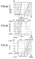
- Figs. 4a to 4c are maps created based on the above concepts.
- the duties assigned to the valves are used as the alternative values of the openings of the EGR valve 21 and intake throttle valve 23.
- the valve opens, and conversely, as the duty for the intake throttle valve 23 increases, the valve closes.
- Fig. 4a shows the opening range limit maps for both valves
- Figs. 4b and 4c show the maps in Fig. 4a resolved for each valve
- Fig. 4b shows the map for the EGR valve 21
- Fig. 4c shown the map for the intake throttle valve 23.
- (1) is related to the EGR valve 21, and (2) is related to the intake throttle valve 23.
- the duty for the intake throttle valve 23 is plotted on the horizontal axis
- the duty for the EGR valve 21 is plotted on the vertical axis, as shown in Figs. 4a and 4b.
- the EGR valve duty is limited to the values that fall within the range shown by the diagonal lines in the graphs in relation to the IT duty. In other words, the values outside of that range are restricted.
- the operable opening range of the EGR valve 21 is limited in accordance with the opening of the intake throttle valve 23.
- the EGR valve duty is limited to 100%; that is, the valve is fully opened. This corresponds to a situation in which point A in Fig. 3 has an IT duty of 40%. Conversely, the limit is gradually eased at the stage in which the IT duty decreases from 40% to 30% (which corresponds to the second opening of the present invention).
- the range of obtainable EGR valve duty proportionally increases, and the EGR valve 21 can be closed from the fully open state to a specific opening determined by the IT duty.
- the IT duty is 30% or lower, the EGR valve duty can assume values from 100% to 0%, the opening range limits do not exist any longer, and the EGR valve 21 can move freely from the fully open state to the fully closed state.
- the EGR valve duty is plotted on the horizontal axis
- the IT duty is plotted on the vertical axis, as shown in Figs. 4a and 4c.
- the IT duty is limited to the values that fall within the range shown by the diagonal lines in the graphs in relation to the EGR valve duty.
- the operable opening range of the intake throttle valve 23 is limited in accordance with the opening of the EGR valve 21.
- the IT valve duty is limited to a value that corresponds to full closure, which ranges from 0% to several percent.
- point B corresponds to an EGR valve duty of 60%.
- the limit is gradually eased at the stage in which the EGR valve duty changes from 60% to 90% (which corresponds to the fourth opening of the present invention).
- the range of obtainable IT duty proportionally increases, and the intake throttle valve 23 can be closed from the fully open state to a specific opening determined by the EGR valve duty.
- the IT duty can assume values from 0% to nearly 100% (95%), the opening range limits do not exist any longer, and the intake throttle valve 23 can move freely from the fully open state to the fully closed state.
- EGR control will now be given based on the flowchart in Fig. 5. This flow is repeated at specific time intervals (several tens of microseconds) by the ECU 26.
- Air mass feedback control is provided to the EGR valve 21 and intake throttle valve 23, and both valves are subjected to conventional air mass feedback control (shown in Fig. 8) up to steps 501 to 504 and 554.
- the actual engine speed Ne, fuel injection volume Q, and air mass volume Ga are first read to the ECU 26 (step 501).
- the engine speed Ne is the value calculated by the ECU 26 on the basis of the output of the engine revolution sensor
- the fuel injection volume Q is the value of the target fuel injection volume calculated by the ECU 26.
- the air mass volume Ga (actual air mass volume) is the value calculated by the ECU 26 on the basis of the output of the air mass sensor 17.
- the target air mass volume Gat is determined according to the map M51 on the basis of the engine speed Ne and fuel injection volume Q (step 502).
- the map M51 is similar to the map M81 in Fig. 8 in that the air-fuel ratio A/F is calculated from the engine speed Ne and fuel injection volume Q, and the target air mass volume Gat is calculated by the ECU 26 from the air-fuel ratio A/F thus obtained.
- the steps are then separated into those for the EGR valve 21 and those for the intake throttle valve 23, and the duties De0 and Di0 for the EGR valve 21 and intake throttle valve 23 are calculated based on the air mass volume deviation ⁇ Ga (steps 504, 554).
- the operations performed during steps 804 and 805 in Fig. 8 are conducted for both valves. More specifically, the proportional gain GP and integral gain GI are calculated from a map similar to the map M82 in Fig.
- the maximum value Dix and minimum value Din obtainable for the IT duty are determined in accordance with the maps M52, M53 on the basis of the feedback duty De0 for the EGR valve (steps 505, 506).
- the maps M52, M53 are obtained by extracting only the corresponding maximum and minimum values on the map in Fig. 4c.
- the obtainable range of the IT duty is thereby determined, and, conversely speaking, the values are limited to that range.
- the obtainable maximum value Dex and minimum value Den of the EGR valve duty are also determined in the same manner for the intake throttle valve in accordance with the maps M54, M55 on the basis of the feedback duty Di0 for the intake throttle valve (steps 555, 556).
- the maps M54, M55 are obtained by extracting only the corresponding maximum and minimum values on the map in Fig. 4b.
- the obtainable range of the EGR valve duty is thereby determined, and, conversely speaking, the values are limited to that range.
- a similar procedure is conducted for the intake throttle valve.
- Figs. 6 and 7 Verified results of the effects of this control are shown in Figs. 6 and 7.
- Fig. 6 is an example of conventional control; that is, an example in which feedback control is provided solely to the EGR valve, and open-loop control is provided to the intake throttle valve.
- Fig. 7 is an example in which the present control is performed. Both are test results obtained from actual equipment, and the graphs display the engine speed values and the target and actual values of the air mass. Conventionally, trackability of the actual values is poor for the target values of the air mass volume, and the two values deviate from each other, as shown in Fig. 6. With the present control, however, the actual values can be tracked nearly completely with respect to the target values of the air mass volume, and there is substantially no deviation between the two, as shown in Fig. 7. It is thereby confirmed that the present control has excellent results.
- the operable opening ranges of the EGR valve and intake throttle valve are thus limited in accordance with the target EGR volume (target air mass volume is used as an alternative value thereof in the present embodiment), thereby enabling correlated control of both valves and ensuring adequate controllability, and at the same time enabling smooth switching and preventing switching shock when control is switched from the EGR valve to the intake throttle valve, or vice versa.
- the operable opening range of either the EGR valve or the intake throttle valve is limited in accordance with the opening of the other valve; therefore, calibrations of the valves with regard to the target EGR volume can be dispensed with and significant time can be saved in creating maps and making calibrations.
- both valves can freely operate within the range of these limitations, making it possible to provide smoother switching and to further prevent switching shocks.
- the ECU 26 comprises the feedback control means, limiting means, and valve opening limiting means of the present invention.
- the portions of the flowchart in Fig. 5 in which steps 501 to 504 and 554 are conducted constitute the feedback control means, and the portions of the flowchart in which other steps are conducted constitute the limiting means and valve opening limiting means.
- the air mass volume was used as an alternative value of the EGR volume
- duty was used as an alternative value of the valve openings
- the EGR volume and valve openings may also be used directly.
- the present invention is also effective when the duty assigned to a valve is fed back to the valve opening.
- the present invention is also effective with regard to an engine provided with an intake throttle valve for DPF regeneration or with lean-rich switching for a lean NOx catalyst.
- the present invention displays excellent effects by which adequate controllability is ensured when feedback control is provided to both the EGR valve and the intake throttle valve with regards to the EGR control, and switching shock is prevented when control is switched from one valve to the other valve.
Landscapes
- Engineering & Computer Science (AREA)
- Chemical & Material Sciences (AREA)
- Combustion & Propulsion (AREA)
- Mechanical Engineering (AREA)
- General Engineering & Computer Science (AREA)
- Output Control And Ontrol Of Special Type Engine (AREA)
- Exhaust-Gas Circulating Devices (AREA)
- Electrical Control Of Air Or Fuel Supplied To Internal-Combustion Engine (AREA)
- Combined Controls Of Internal Combustion Engines (AREA)
- Control Of Throttle Valves Provided In The Intake System Or In The Exhaust System (AREA)
Applications Claiming Priority (2)
| Application Number | Priority Date | Filing Date | Title |
|---|---|---|---|
| JP2001364638A JP3885569B2 (ja) | 2001-11-29 | 2001-11-29 | 内燃機関のegr制御装置 |
| JP2001364638 | 2001-11-29 |
Publications (3)
| Publication Number | Publication Date |
|---|---|
| EP1316702A2 true EP1316702A2 (fr) | 2003-06-04 |
| EP1316702A3 EP1316702A3 (fr) | 2004-05-26 |
| EP1316702B1 EP1316702B1 (fr) | 2010-07-28 |
Family
ID=19174792
Family Applications (1)
| Application Number | Title | Priority Date | Filing Date |
|---|---|---|---|
| EP02025737A Expired - Lifetime EP1316702B1 (fr) | 2001-11-29 | 2002-11-15 | Appareil permettant d'agir sur la recirculation d'egr d'un moteur à combustion |
Country Status (4)
| Country | Link |
|---|---|
| US (1) | US6725832B2 (fr) |
| EP (1) | EP1316702B1 (fr) |
| JP (1) | JP3885569B2 (fr) |
| DE (1) | DE60237138D1 (fr) |
Cited By (4)
| Publication number | Priority date | Publication date | Assignee | Title |
|---|---|---|---|---|
| US7290528B2 (en) | 2003-10-23 | 2007-11-06 | Hitachi, Ltd. | Exhaust gas recirculation device for internal combustion engine |
| WO2012010462A1 (fr) * | 2010-07-23 | 2012-01-26 | Bayerische Motoren Werke Aktiengesellschaft | Augmentation du taux de recyclage des gaz d'échappement lorsque la soupape de recyclage des gaz d'échappement est déjà totalement ouverte |
| EP2653704A1 (fr) * | 2010-12-16 | 2013-10-23 | Toyota Jidosha Kabushiki Kaisha | Appareil de commande de moteur à combustion interne |
| CN111720204A (zh) * | 2019-03-21 | 2020-09-29 | 上海汽车集团股份有限公司 | 一种发动机的控制方法及其装置 |
Families Citing this family (20)
| Publication number | Priority date | Publication date | Assignee | Title |
|---|---|---|---|---|
| JP2003336549A (ja) * | 2002-05-20 | 2003-11-28 | Denso Corp | 内燃機関のegr装置 |
| JP4015889B2 (ja) * | 2002-06-28 | 2007-11-28 | 株式会社豊田自動織機 | 内燃機関のegr制御装置 |
| WO2004053322A1 (fr) * | 2002-12-11 | 2004-06-24 | Bosch Automotive Systems Corporation | Dispositif de recirculation des gaz d'echappement |
| DE10307166A1 (de) * | 2003-02-20 | 2004-09-09 | Daimlerchrysler Ag | Verfahren zum Betrieb einer fremdgezündeten Brennkraftmaschine |
| JP2005054588A (ja) * | 2003-08-04 | 2005-03-03 | Isuzu Motors Ltd | 内燃機関の制御装置 |
| JP2006161569A (ja) * | 2004-12-02 | 2006-06-22 | Mitsubishi Fuso Truck & Bus Corp | 内燃機関のegr制御装置 |
| JP4522914B2 (ja) * | 2005-06-15 | 2010-08-11 | 本田技研工業株式会社 | 内燃機関のegr制御装置 |
| JP2007032462A (ja) * | 2005-07-28 | 2007-02-08 | Daihatsu Motor Co Ltd | Egr制御方法、egr制御装置 |
| JP2007270642A (ja) * | 2006-03-30 | 2007-10-18 | Mitsubishi Fuso Truck & Bus Corp | 内燃機関のegr制御装置 |
| JP2008215112A (ja) | 2007-02-28 | 2008-09-18 | Mitsubishi Heavy Ind Ltd | ディーゼルエンジンシステム及びその制御方法 |
| FR2926114B1 (fr) * | 2008-01-03 | 2012-12-14 | Valeo Sys Controle Moteur Sas | Boucle egr d'un moteur a combustion interne d'un vehicule automobile |
| JP4859875B2 (ja) * | 2008-05-12 | 2012-01-25 | 三菱重工業株式会社 | ディーゼルエンジンの排ガス再循環制御装置 |
| JP2010236448A (ja) * | 2009-03-31 | 2010-10-21 | Yamaha Motor Co Ltd | 水ジェット推進艇 |
| JP2010242612A (ja) * | 2009-04-06 | 2010-10-28 | Yamaha Motor Co Ltd | 水ジェット推進艇 |
| JP2015086715A (ja) * | 2013-10-28 | 2015-05-07 | トヨタ自動車株式会社 | 内燃機関の吸気量制御装置 |
| JP6237654B2 (ja) | 2015-01-14 | 2017-11-29 | トヨタ自動車株式会社 | 内燃機関の制御装置 |
| BR102016006973A2 (pt) | 2015-03-31 | 2016-11-01 | Toyota Motor Co Ltd | dispositivo de controle para motor de combustão interna |
| JP6052444B2 (ja) * | 2015-03-31 | 2016-12-27 | トヨタ自動車株式会社 | 内燃機関の制御装置 |
| JP6274183B2 (ja) | 2015-11-06 | 2018-02-07 | トヨタ自動車株式会社 | 内燃機関の制御装置 |
| KR102518657B1 (ko) * | 2018-07-12 | 2023-04-06 | 현대자동차주식회사 | 밸브 듀티 차등화 방식 egr 제어 방법 및 egr 시스템 |
Citations (3)
| Publication number | Priority date | Publication date | Assignee | Title |
|---|---|---|---|---|
| EP0887532A2 (fr) * | 1997-06-26 | 1998-12-30 | Toyota Jidosha Kabushiki Kaisha | Dispositif de commande pour papillon d'admission d'air de moteur à combustion interne |
| DE19944832A1 (de) * | 1999-09-18 | 2001-03-22 | Bosch Gmbh Robert | Verfahren und Vorrichtung zur Steuerung einer Brennkraftmaschine |
| US6209530B1 (en) * | 1997-07-03 | 2001-04-03 | Caterpillar Inc. | Control system for exhaust gas recirculation system |
Family Cites Families (8)
| Publication number | Priority date | Publication date | Assignee | Title |
|---|---|---|---|---|
| JPH074319A (ja) | 1993-06-17 | 1995-01-10 | Nissan Motor Co Ltd | ディーゼルエンジンのegr装置 |
| JPH08158953A (ja) | 1994-11-30 | 1996-06-18 | Aisin Seiki Co Ltd | Egr制御装置 |
| JPH08210195A (ja) | 1995-02-06 | 1996-08-20 | Nissan Motor Co Ltd | ディーゼル機関の排気還流制御装置 |
| JPH0979091A (ja) | 1995-09-12 | 1997-03-25 | Toyota Motor Corp | ディーゼル機関の排気ガス再循環装置 |
| JP3511807B2 (ja) * | 1996-07-09 | 2004-03-29 | 日産自動車株式会社 | エンジンの吸気制御装置 |
| EP0884464B1 (fr) * | 1997-06-10 | 2004-09-08 | Nissan Motor Company, Limited | Moteur à combustion interne |
| JPH1136929A (ja) * | 1997-07-23 | 1999-02-09 | Mazda Motor Corp | エンジンの吸気制御装置 |
| JP2000303914A (ja) * | 1999-04-23 | 2000-10-31 | Mazda Motor Corp | エンジンの排気ガス還流装置 |
-
2001
- 2001-11-29 JP JP2001364638A patent/JP3885569B2/ja not_active Expired - Fee Related
-
2002
- 2002-11-15 DE DE60237138T patent/DE60237138D1/de not_active Expired - Lifetime
- 2002-11-15 EP EP02025737A patent/EP1316702B1/fr not_active Expired - Lifetime
- 2002-11-25 US US10/303,533 patent/US6725832B2/en not_active Expired - Fee Related
Patent Citations (3)
| Publication number | Priority date | Publication date | Assignee | Title |
|---|---|---|---|---|
| EP0887532A2 (fr) * | 1997-06-26 | 1998-12-30 | Toyota Jidosha Kabushiki Kaisha | Dispositif de commande pour papillon d'admission d'air de moteur à combustion interne |
| US6209530B1 (en) * | 1997-07-03 | 2001-04-03 | Caterpillar Inc. | Control system for exhaust gas recirculation system |
| DE19944832A1 (de) * | 1999-09-18 | 2001-03-22 | Bosch Gmbh Robert | Verfahren und Vorrichtung zur Steuerung einer Brennkraftmaschine |
Non-Patent Citations (1)
| Title |
|---|
| PATENT ABSTRACTS OF JAPAN vol. 1998, no. 05, 30 April 1998 (1998-04-30) -& JP 10 026038 A (NISSAN MOTOR CO LTD), 27 January 1998 (1998-01-27) * |
Cited By (5)
| Publication number | Priority date | Publication date | Assignee | Title |
|---|---|---|---|---|
| US7290528B2 (en) | 2003-10-23 | 2007-11-06 | Hitachi, Ltd. | Exhaust gas recirculation device for internal combustion engine |
| WO2012010462A1 (fr) * | 2010-07-23 | 2012-01-26 | Bayerische Motoren Werke Aktiengesellschaft | Augmentation du taux de recyclage des gaz d'échappement lorsque la soupape de recyclage des gaz d'échappement est déjà totalement ouverte |
| EP2653704A1 (fr) * | 2010-12-16 | 2013-10-23 | Toyota Jidosha Kabushiki Kaisha | Appareil de commande de moteur à combustion interne |
| EP2653704A4 (fr) * | 2010-12-16 | 2014-03-26 | Toyota Motor Co Ltd | Appareil de commande de moteur à combustion interne |
| CN111720204A (zh) * | 2019-03-21 | 2020-09-29 | 上海汽车集团股份有限公司 | 一种发动机的控制方法及其装置 |
Also Published As
| Publication number | Publication date |
|---|---|
| JP2003166445A (ja) | 2003-06-13 |
| EP1316702A3 (fr) | 2004-05-26 |
| EP1316702B1 (fr) | 2010-07-28 |
| DE60237138D1 (de) | 2010-09-09 |
| US6725832B2 (en) | 2004-04-27 |
| JP3885569B2 (ja) | 2007-02-21 |
| US20030098014A1 (en) | 2003-05-29 |
Similar Documents
| Publication | Publication Date | Title |
|---|---|---|
| US6725832B2 (en) | EGR control apparatus for internal combustion engine | |
| US7076953B2 (en) | Method for controlling an engine with VGT and EGR systems | |
| US9759141B2 (en) | Controlling apparatus for engine | |
| JP4251073B2 (ja) | 内燃機関の制御装置 | |
| JP4462327B2 (ja) | 気筒特性ばらつき検出装置 | |
| JP4525729B2 (ja) | Egr分配ばらつき検出装置 | |
| US6363922B1 (en) | Exhaust gas recirculation pressure differential sensor error compensation | |
| US9885303B2 (en) | Control device for diesel engine | |
| EP2128407A1 (fr) | Contrôleur d'egr destiné à un moteur à combustion interne | |
| US9464585B2 (en) | Exhaust gas recirculation control system of engine | |
| US20030075158A1 (en) | Method and device for a mass flow determination via a control valve and for determining a modeled induction pipe pressure | |
| JP3888024B2 (ja) | 排気ガス再循環装置 | |
| US7769526B2 (en) | Diesel transient combustion control based on intake carbon dioxide concentration | |
| US7367311B2 (en) | Control system for compression ignition internal combustion engine | |
| US10273911B2 (en) | EGR control device | |
| EP2189647B1 (fr) | Contrôleur de pression d'admission pour moteur à combustion interne | |
| US20120022763A1 (en) | Internal exhaust gas recirculation control in an internal combustion engine | |
| EP3075991B1 (fr) | Dispositif de contrôle pour moteur à combustion interne | |
| JP2004245062A (ja) | 内燃機関の可変吸気装置 | |
| JP4000923B2 (ja) | 車両用ターボ過給式ディーゼルエンジンの吸気絞り弁制御装置 | |
| JP4438773B2 (ja) | ターボ過給機の制御装置 | |
| JPH04101031A (ja) | 内燃機関の燃料供給装置 | |
| JP3859011B2 (ja) | ターボ過給機の制御装置 | |
| JP2013253532A (ja) | 過給エンジンのegr装置 | |
| JP2001059453A (ja) | ディーゼルエンジンの制御装置 |
Legal Events
| Date | Code | Title | Description |
|---|---|---|---|
| PUAI | Public reference made under article 153(3) epc to a published international application that has entered the european phase |
Free format text: ORIGINAL CODE: 0009012 |
|
| AK | Designated contracting states |
Designated state(s): AT BE BG CH CY CZ DE DK EE ES FI FR GB GR IE IT LI LU MC NL PT SE SK TR |
|
| AX | Request for extension of the european patent |
Extension state: AL LT LV MK RO SI |
|
| PUAL | Search report despatched |
Free format text: ORIGINAL CODE: 0009013 |
|
| AK | Designated contracting states |
Kind code of ref document: A3 Designated state(s): AT BE BG CH CY CZ DE DK EE ES FI FR GB GR IE IT LI LU MC NL PT SE SK TR |
|
| AX | Request for extension of the european patent |
Extension state: AL LT LV MK RO SI |
|
| 17P | Request for examination filed |
Effective date: 20040923 |
|
| AKX | Designation fees paid |
Designated state(s): DE FR GB IT |
|
| RBV | Designated contracting states (corrected) |
Designated state(s): DE FR GB IT |
|
| 17Q | First examination report despatched |
Effective date: 20060926 |
|
| 17Q | First examination report despatched |
Effective date: 20060926 |
|
| GRAP | Despatch of communication of intention to grant a patent |
Free format text: ORIGINAL CODE: EPIDOSNIGR1 |
|
| GRAS | Grant fee paid |
Free format text: ORIGINAL CODE: EPIDOSNIGR3 |
|
| GRAA | (expected) grant |
Free format text: ORIGINAL CODE: 0009210 |
|
| AK | Designated contracting states |
Kind code of ref document: B1 Designated state(s): DE FR GB IT |
|
| REG | Reference to a national code |
Ref country code: GB Ref legal event code: FG4D |
|
| REF | Corresponds to: |
Ref document number: 60237138 Country of ref document: DE Date of ref document: 20100909 Kind code of ref document: P |
|
| PGFP | Annual fee paid to national office [announced via postgrant information from national office to epo] |
Ref country code: IT Payment date: 20101126 Year of fee payment: 9 |
|
| PLBE | No opposition filed within time limit |
Free format text: ORIGINAL CODE: 0009261 |
|
| STAA | Information on the status of an ep patent application or granted ep patent |
Free format text: STATUS: NO OPPOSITION FILED WITHIN TIME LIMIT |
|
| 26N | No opposition filed |
Effective date: 20110429 |
|
| REG | Reference to a national code |
Ref country code: DE Ref legal event code: R097 Ref document number: 60237138 Country of ref document: DE Effective date: 20110429 |
|
| PG25 | Lapsed in a contracting state [announced via postgrant information from national office to epo] |
Ref country code: IT Free format text: LAPSE BECAUSE OF NON-PAYMENT OF DUE FEES Effective date: 20111115 |
|
| PGFP | Annual fee paid to national office [announced via postgrant information from national office to epo] |
Ref country code: FR Payment date: 20121130 Year of fee payment: 11 |
|
| PGFP | Annual fee paid to national office [announced via postgrant information from national office to epo] |
Ref country code: DE Payment date: 20131113 Year of fee payment: 12 Ref country code: GB Payment date: 20131113 Year of fee payment: 12 |
|
| REG | Reference to a national code |
Ref country code: FR Ref legal event code: ST Effective date: 20140731 |
|
| PG25 | Lapsed in a contracting state [announced via postgrant information from national office to epo] |
Ref country code: FR Free format text: LAPSE BECAUSE OF NON-PAYMENT OF DUE FEES Effective date: 20131202 |
|
| REG | Reference to a national code |
Ref country code: DE Ref legal event code: R082 Ref document number: 60237138 Country of ref document: DE Representative=s name: SCHAUMBURG & PARTNER PATENTANWAELTE GBR, DE Ref country code: DE Ref legal event code: R082 Ref document number: 60237138 Country of ref document: DE Representative=s name: SCHAUMBURG UND PARTNER PATENTANWAELTE MBB, DE |
|
| REG | Reference to a national code |
Ref country code: DE Ref legal event code: R119 Ref document number: 60237138 Country of ref document: DE |
|
| GBPC | Gb: european patent ceased through non-payment of renewal fee |
Effective date: 20141115 |
|
| PG25 | Lapsed in a contracting state [announced via postgrant information from national office to epo] |
Ref country code: DE Free format text: LAPSE BECAUSE OF NON-PAYMENT OF DUE FEES Effective date: 20150602 Ref country code: GB Free format text: LAPSE BECAUSE OF NON-PAYMENT OF DUE FEES Effective date: 20141115 |