EP1312526A1 - Doppelstöckige Eisenbahnwagen mit Durchgangseinrichtungen in beiden Stöcken - Google Patents
Doppelstöckige Eisenbahnwagen mit Durchgangseinrichtungen in beiden Stöcken Download PDFInfo
- Publication number
- EP1312526A1 EP1312526A1 EP01660206A EP01660206A EP1312526A1 EP 1312526 A1 EP1312526 A1 EP 1312526A1 EP 01660206 A EP01660206 A EP 01660206A EP 01660206 A EP01660206 A EP 01660206A EP 1312526 A1 EP1312526 A1 EP 1312526A1
- Authority
- EP
- European Patent Office
- Prior art keywords
- coaches
- bridge
- wheels
- successive
- coach
- Prior art date
- Legal status (The legal status is an assumption and is not a legal conclusion. Google has not performed a legal analysis and makes no representation as to the accuracy of the status listed.)
- Granted
Links
Images

Classifications
-
- B—PERFORMING OPERATIONS; TRANSPORTING
- B61—RAILWAYS
- B61D—BODY DETAILS OR KINDS OF RAILWAY VEHICLES
- B61D3/00—Wagons or vans
- B61D3/10—Articulated vehicles
-
- B—PERFORMING OPERATIONS; TRANSPORTING
- B60—VEHICLES IN GENERAL
- B60D—VEHICLE CONNECTIONS
- B60D5/00—Gangways for coupled vehicles, e.g. of concertina type
- B60D5/006—Passages between articulated vehicles, e.g. bridges or rotating plates
-
- B—PERFORMING OPERATIONS; TRANSPORTING
- B61—RAILWAYS
- B61D—BODY DETAILS OR KINDS OF RAILWAY VEHICLES
- B61D1/00—Carriages for ordinary railway passenger traffic
- B61D1/06—Carriages for ordinary railway passenger traffic with multiple deck arrangement
-
- B—PERFORMING OPERATIONS; TRANSPORTING
- B61—RAILWAYS
- B61D—BODY DETAILS OR KINDS OF RAILWAY VEHICLES
- B61D17/00—Construction details of vehicle bodies
- B61D17/04—Construction details of vehicle bodies with bodies of metal; with composite, e.g. metal and wood body structures
- B61D17/20—Communication passages between coaches; Adaptation of coach ends therefor
- B61D17/22—Communication passages between coaches; Adaptation of coach ends therefor flexible, e.g. bellows
-
- B—PERFORMING OPERATIONS; TRANSPORTING
- B62—LAND VEHICLES FOR TRAVELLING OTHERWISE THAN ON RAILS
- B62D—MOTOR VEHICLES; TRAILERS
- B62D31/00—Superstructures for passenger vehicles
- B62D31/04—Superstructures for passenger vehicles with more than one deck
-
- B—PERFORMING OPERATIONS; TRANSPORTING
- B60—VEHICLES IN GENERAL
- B60Y—INDEXING SCHEME RELATING TO ASPECTS CROSS-CUTTING VEHICLE TECHNOLOGY
- B60Y2200/00—Type of vehicle
- B60Y2200/30—Railway vehicles
Definitions
- the invention relates to an intercommunicating passageway between double-decker articulated railway coaches, which have a limited kinematic gauge, and which comprise a lower passenger room with an inner height and a first floor at a lower level, and an upper passenger room with an inner height and a second floor at a higher level, on top of said lower passenger room.
- Publication DE-43 35 420 concerns an intercommunicating area for coaches with staircases for double decker rail vehicles, which is designed in such a way that persons moving rapidly into the upper decker by means of stairs quickly orientate themselves there and move comfortably to the seats of the respective coaches.
- the publication describes disadvantages in the double decker rail vehicles relating to the intercommunicating area in the upper decker and the staircase so that for example there is the problem of an excessively narrow passage and staircase connection in the upper deck and the resulting waste of space in the coach.
- these problems are solved by locating the stairs and corridors of the two coupled coaches in the end region of the coaches diagonally opposite one another, as a result of which an X-shaped arrangement is produced, whereupon these stairs and corridors continue from a single bridge extending from coach to coach therebetween at a somewhat lower level than the upper deckers of the coupled coaches.
- the combination of the functions of the exit areas from the stairs and the intercommunicating area between coaches at the coupling point of each body is said to permit a space-saving walk-trough area to be provided.
- Publication EP-0 336 809 discloses a double-decker car-carrying railway wagon with a deformable elastic membrane in the intercommunicating passage between the wagons.
- the main subject of the publication is the construction and configuration of the bellows, by which a free transport of vehicles and passengers is tried to obtain.
- the publication also shows two continuous floors, which assure prolongation of wagon floors with the aid of an appropriate deformation, and which are so enclosed within the bellows, too. How this could be possible is not explained.
- These kind of wagons are intended for transport of cars trough the English Channel, for which purpose the outer dimensions of the wagons are much greater than those allowable for ordinary railway networks.
- the lower floor of the wagon continues as a single plane between the universally used two axle bogies with four wheels and above these two axle bogies, which is not possible in wagons and coaches having standard kinematic gauge or profile according to UIC Code 505-1 OR Appendix 4, which defines a maximum height of 4660 mm or 4310 mm, because under these circumstances the room between the upper side of the two axle bogie and the upper limit of the gauge does not allow acceptable heights for two floors or decks. I.e.
- GB-589 565 and GB-1 508 173 disclose articulated railway vehicles, in which the wheels are so guided that they strike the track at a small negative angle on incidence thus enabling the train to be constructed of light weight material and run at high speed without danger of derailment.
- this condition is attained by mounting a pair of wheels on a bogie or truck, which is disposed between two adjacent vehicles, and which is adapted to be locked to one or the other of said vehicles according to the direction of running.
- the wheels are mounted on the bogie independently of each other about a common axis line.
- the latter publication GB-1 508 173 describes improvements to the articulated railway vehicles having a car body, one end of which is supported by a running gear frame or bogie frame or yoke provided with the pair of wheels.
- the car body is further supported on springs bearing upon the running gear frame and located independently from one another symmetrically on each side of the central vertical longitudinal plane of the car.
- the springs are adjustable pneumatic springs in order to reduce the passenger awareness of unbalanced centrifugal force, only when the train reaches a speed above a predetermined minimum, and only when the track has a sufficient predetermined degree of curvature.
- the main object of the invention is to further improve the effective rate of coverage with seats in the railway coaches used in ordinary railway networks.
- the passenger coach has an outer profile in accordance to UIC Code 505-1 OR Appendix 4, an outer profile in accordance to other respective Codes or Standards applicable for ordinary railways at least in railway networks including extending into cities, towns and the like, and that the coach should have as a many seats as possible.
- the second object of the invention is to enable such constructional features in the coach that the train can run without functional problems at high speeds.
- the third object of the invention is to enable said improvement with as simple and reliable a construction as possible, and to avoid any excessive costs.
- a wheel frame at an area between two successive coaches, and having a lowered center section and a pair of wheels supported by and connected trough separate bearings to said wheel frame;
- Fig. 1 illustrates generally a part of a train provided with the intercommunicating passageways between double-decker articulated railway coaches according to the invention, in a longitudinal section trough the vertical center plane I-I of Fig. 2.
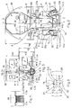
- Fig. 2 illustrates an intercommunicating passageway according to the invention having a lower bridge and an upper bridge, as well as the wheel frame arrangement with a pair of independently rolling wheels between the successive coaches, partially in a transverse section trough the vertical plane II-II of Fig. 1 and partially in the respective direction.
- Fig. 3 illustrates an intercommunicating passageway of Fig. 1, and the wheel frame arrangement with a pair of independent wheels between the successive coaches, in the same view as in Fig. 2, but on a larger scale.
- Fig. 4 illustrates a detail of the bellows comprised by and surrounding the intercommunicating passageway according to the invention from the area IV of Fig. 3.
- Fig. 5 illustrates diagrammatically the bridges at the lower and upper floor of the coaches extending from coach to coach within the intercommunicating passageway according to the invention in a plan view V of Fig. 2.
- Fig. 6 shows generally a part of a train according to Prior Art, in which each coach is provided with bogie units, each of which being two axle bogies at both ends of each coach, as well as a single floor in the area the intercommunicating passageway, in the same view as Fig. 1.
- the intercommunicating passageway 9 between double-decker articulated railway coaches 1 according to the invention is a combination of several constructional features.
- the double-decker coaches 1 for passengers have a lower passenger room 7 and an upper passenger room 8 on top of the lower passenger room.
- the lower passenger room has an inner height H3 and a first floor 3 at a first lower level H1a with seats as shown in Fig. 1, and providing necessary vertical room for the passengers to walk along the coach as well as to and from their seats.
- the first floor 3 of the lower passenger room 7 is positioned between the pairs 23 of wheels 13a, 13b at the ends 24, 25 of each of the coaches as described later, i.e. at a level, which is downward from the line going through the highest point of the wheels.
- the upper passenger room 8 has an inner height H4 and a second floor 4 at a higher level H2 with seats as shown in Fig. 1, and providing necessary vertical room for the passengers to walk along the coach as well as to and from their seats.
- the upper passenger room above the lower passenger room has a length L4 substantially equal with the length L1 of the coach 1 as practically do the length L3 of the lower passenger room, which assure a very high utilization of the total room inside the coaches.
- the length L3 of the lower passenger room is only slightly shorter than the total length L1 of the coach because of the suspension means 29 for the pair of wheels with their wheel frame 10 between the coaches, disclosed later in detail.
- the longitudinal room required by this one set of suspension means 29 included at least partially in the gap 26 - which is always needed - between the adjacent ends 24, 25 of the successive coaches means very small loss of useful space in the lower passenger room and practically no loss of useful space in the upper passenger room.
- staircases 35 between the upper passenger room 8 and the lower passenger room 7 but one bare staircase in a coach causes a decrease of a few seats only.
- the height portion Hp between the upper limit of a standard kinematic gauge and said wheels is smaller than the sum H3+H4 of the inner heights of two superimposed passenger rooms 7, 8, i.e. H3+H4 ⁇ Hp.
- the headrooms - that is the spacing between the decks or floors should have been summed - but because the thickness of the floors and the roof in the coaches are very small as compared to the inner heights, these thicknesses can be neglected.
- the sum of this said height portion Hp and the rolling diameter ⁇ of the wheels shall be at maximum equal with the vertical kinematic gauge or smaller than the vertical kinematic gauge, i.e.
- the diameters ⁇ of the wheels 12a, 12b depends on the weights loading them and on the required speed of the train. Typically the wheel diameters ⁇ are at least 800 mm and preferably in the order of 900 mm to 950 mm.
- the inner height H3 of the lower passenger rooms 7 is substantially equal with the inner height H4 of the upper passenger rooms 8.
- the adjacent ends 24, 25 of each of two successive coaches 1a and 1b or 1b and 1a are both supported by the wheel frame 10, which is positioned, with its wheels 13a, 13b, at the area - at least partly within the gap 26 - between two successive coaches.
- the reference number 1 is used generally for the coaches, and the reference numbers 1a, 1b are used for occasions, in which the successive coaches shall be distinguished from each other, only.
- the gap 26 between the adjacent ends 24, 25 of the successive coaches are needed to provide room for turning the coaches in respect to each other along a curved passage of rails, i.e. to allow an angle deviating from 180° between the longitudinal axis of the successive coaches.
- the wheel frame has a lowered center section 11, which means that the wheel frame 10 has a form of the letter ⁇ in the direction transversal to the length L1 of the coach, and a pair of wheels 12a, 12b supported by and connected trough separate bearings 13 to said wheel frame, as visible in the Figure 2.
- These wheels 12a, 12b in the pair 23 of wheels have a common axle line 14, but not a common shaft.
- the coaches further comprise suspension means 29 mounted between the wheel frame 10 and a coach body at two points 28a, 28b having a spacing W2 therebetween in transversal direction of the coach.
- the suspension means 29 are rigidly attached at these two points 28a, 28b to the body of one of the two successive coaches, at the support area 27c close to the end thereof, and the end of the other of the two successive coaches is supported via a pair of carrying bars 27a, 27b at both longitudinal sides of the coaches and crossing the gap 26. So the load from both adjacent ends 24, 25 of two successive coaches are carried through the suspension means 26 and a single wheel frame 10 with the pair 23 of wheels.
- the successive coaches 1a, 1b further comprise two pairs 30 of connection rods 31a, 31b therebetween. The connection rods in both pairs 30, each at one longitudinal side of the coaches, being longitudinally successive and interposed by a control lever 32 through articulations 33.
- Each of the control levers 32 is pivotally secured to one of the transversally opposite end regions of the wheel frame 10, and the connection rods being coupled with stationary articulations 34 with the mutually opposite ends of the successive coaches.
- Connecting rods 31a, 31b and the control lever 32 across the gap 26 halves the mutual longitudinal movements on both sides of the train, on one side a shortening movement and on the other side a lengthening movement, for the wheel frame so creating the parallelism between the tangent of the rails and the rolling plane of the wheels.
- a first bridge 5 extending between two successive coaches 1a, 1b, the first bridge being substantially at a second lower level H1b and on the first floors 3 of the coaches connected, and further a second bridge 6 extending between the two successive coaches 1a, 1b.
- the first lower level H1a of the first floors and second lower levels H1b of the first bridges are down from the highest peripheral point P of the wheels.
- the second lower level H1b is at a slightly higher level than the first lower level H1a, there being a small height difference ⁇ H, whereupon the second lower level H1b of the first bridge 5 is positioned at a height, which is between the axle line 14 and the highest peripheral point P of the wheels.
- the first floors 3 are provided with a ramps 36 at both ends of the coach rising from the first lower level H1a to the second lower level H1b.
- the first bridge substantially at the same level as the first floor 3.
- both the second lower level H1b of the first bridge and the first lower level H1a of the first floors can be so low as approximately at the height of the axle line 14.
- first lower level H1a of the first floors 3 and the second lower level H1b of the first bridges 5 are down from the highest peripheral point P of the wheels, and typically somewhere between the highest peripheral point P and the common axle line 14 of the wheels. So the first bridge 5 extends from coach to coach 1b to 1a to 1b etc. between the wheels 12a and 12b of the pair of wheels and above the lowered center section 11 of the wheel frame 10.
- the second bridge 6 is substantially at the same higher level H2 with the second floors 4 of the coaches connected.
- the first bridge 5 typically rests against the first floors 3 or against the ramps 36 thereof of the successive and adjacent coaches. In a similar way the second bridge 6 typically rest against second floors 4 of the successive and adjacent coaches. If only possible the second lower level H1b of the first bridge 5 should be closer to a common axle line 14 of said pair of wheels than the highest peripheral point P of the wheels.
- the intercommunicating passageway has, according to the invention, a upper walkin 15 above or upwards from the first bridge 5, continuing from a lower passenger room 7 in one of the successive coaches 1a or 1b to a lower passenger room 7 in another of the successive coaches 1b or 1a.
- the upper walkin 15 extending from coach to coach along and within the spacing W2 between the mounting points 28a, 28b of the suspension means to the coach.
- This upper walkin 15 has an inner height H5 substantially the same as, or approaching that H3 of the lower passenger rooms.
- the possible difference between the inner height H5 of the upper walkin and the inner height H3 of the lower passenger room 7 is the height difference ⁇ H, which is a fraction of the inner height H3 of the lower passenger room.
- the height difference ⁇ H is smaller than 20%, preferably smaller than 15%, and typically from 5% to 10% of the inner height H3 of the lower passenger room.
- the intercommunicating passageway has, according to the invention, also a lower walkin 16 above the second bridge 6, continuing from an upper passenger room 8 in one of the successive coaches 1a or 1b to an upper passenger room 8 in another of the successive coaches 1b or 1a.
- This lower walkin has an inner height H6 approaching that H4 of the upper passenger rooms.
- the inner height H6 of the lower walkin 16 is practically the same as the inner height H4 of the upper passenger rooms.
- the height variations in the order of bridge thicknesses shall be considered unessential, while the thickness of the bridges 5, 6 can be extremely small, like 10 mm 30 mm, because of the low loads caused by passengers and the shortness of the gap 26 between the coaches.
- the upper walkin 15 has an inner width W5, which is substantially smaller than inner width W3 of the lower passenger rooms 7, and the lower walkin 16 has an inner width W6, which is substantially smaller than inner width W4 of the upper passenger rooms 8.
- one of the successive coaches comprises a lock 20 fixed in the first floor 3 and attaching the first bridge 5 to the coach pivotally around a vertical line V and a lock 20 fixed in the second floor 4 and attaching second bridge 6 to the coach pivotally around a vertical line V.
- the locks 20 may be simple vertical pin construction close to one longitudinal end of the bridges configured to prohibit unintentional removing of the bridge and to allow pivotal movement of the bridge around the vertical line V, which goes trough the pin. The pivotal movement happens when the train goes along a curved rail passage.
- the another of the adjacent and successive coaches comprises a pair of side stops 21 fixed in the first floor 3, and a pair of side stops 21 fixed in the second floor 4, whereupon the side stops are located transversally at both sides of the first and the second bridge 5,6.
- the side stops may also include configurations for attachment of the bridges to the respective coach 1, and prohibiting unintentional removing of the bridges.
- the coaches further comprise bellows means 26 surrounding the passageway.
- the bellows means 29 are positioned substantially inwards from the kinematic gauge applied, and so the bellows means 26 goes along the predetermined limit line or area of the combination of the upper walkin 16 and the lower walkin 15, as clearly shown in Fig. 2. This arrangement ensures lower noise in the walkins, promotes tidiness and maintains the passengers to experience the walkins as parts of the actual passenger rooms 7, 8.
Landscapes
- Engineering & Computer Science (AREA)
- Mechanical Engineering (AREA)
- Transportation (AREA)
- Life Sciences & Earth Sciences (AREA)
- Wood Science & Technology (AREA)
- Chemical & Material Sciences (AREA)
- Combustion & Propulsion (AREA)
- Body Structure For Vehicles (AREA)
- Mechanical Coupling Of Light Guides (AREA)
- Paper (AREA)
- Bridges Or Land Bridges (AREA)
- Management, Administration, Business Operations System, And Electronic Commerce (AREA)
- Road Paving Structures (AREA)
- Cage And Drive Apparatuses For Elevators (AREA)
- Air Bags (AREA)
- Fluid-Pressure Circuits (AREA)
- Passenger Equipment (AREA)
- Interconnected Communication Systems, Intercoms, And Interphones (AREA)
- Artificial Fish Reefs (AREA)
- Vehicle Body Suspensions (AREA)
- Platform Screen Doors And Railroad Systems (AREA)
Priority Applications (17)
| Application Number | Priority Date | Filing Date | Title |
|---|---|---|---|
| TR2004/01873T TR200401873T4 (tr) | 2001-11-16 | 2001-11-16 | Çift katlı demiryolu yolcu vagonlarında birbirlerine bağlı geçitler. |
| DK01660206T DK1312526T3 (da) | 2001-11-16 | 2001-11-16 | Dobbeltdækkerjernbanevogne med indbyrdes forbundne korridorer på begge niveauer |
| AT01660206T ATE265344T1 (de) | 2001-11-16 | 2001-11-16 | Doppelstöckige eisenbahnwagen mit durchgangseinrichtungen in beiden stöcken |
| DE60103069T DE60103069T2 (de) | 2001-11-16 | 2001-11-16 | Doppelstöckige Eisenbahnwagen mit Durchgangseinrichtungen in beiden Stöcken |
| EP01660206A EP1312526B1 (de) | 2001-11-16 | 2001-11-16 | Doppelstöckige Eisenbahnwagen mit Durchgangseinrichtungen in beiden Stöcken |
| PT01660206T PT1312526E (pt) | 2001-11-16 | 2001-11-16 | Carruagens ferroviarias de duplo andar com passagens intercomunicantes em ambos os niveis |
| ES01660206T ES2217106T3 (es) | 2001-11-16 | 2001-11-16 | Vagones de ferrocarril de dos pisos con pasos de intercomunicacion en cada piso. |
| AU2002301373A AU2002301373B2 (en) | 2001-11-16 | 2002-10-02 | Intercommunicating passageways in double-decker railway coaches |
| CA2407980A CA2407980C (en) | 2001-11-16 | 2002-10-11 | Intercommunicating passageways in double-decker railway coaches |
| RU2002129997/11A RU2296685C2 (ru) | 2001-11-16 | 2002-11-12 | Соединительный проход между двухэтажными железнодорожными пассажирскими вагонами |
| US10/293,225 US6945176B2 (en) | 2001-11-16 | 2002-11-13 | Intercommunicating passageways in double-decker railway coaches |
| KR1020020070241A KR20030040121A (ko) | 2001-11-16 | 2002-11-13 | 2층 구조의 연접식 철도 객차 사이의 연결 통로 |
| CZ2002-3788A CZ304245B6 (cs) | 2001-11-16 | 2002-11-14 | Spojovací průchod mezi dvoupodlažními kloubovými železničními vozy |
| MXPA02011259A MXPA02011259A (es) | 2001-11-16 | 2002-11-14 | Pasajes de intercomunicacion en los carros de ferrocarril de dos pisos. |
| PL357153A PL201095B1 (pl) | 2001-11-16 | 2002-11-15 | Zestaw dwupoziomowych przegubowych wagonów kolejowych z przejściami łaczącymi |
| CNB021506736A CN100333951C (zh) | 2001-11-16 | 2002-11-18 | 双层铰接式铁路客车组 |
| JP2002334232A JP2003154933A (ja) | 2001-11-16 | 2002-11-18 | 二階建て鉄道客車における連絡通路 |
Applications Claiming Priority (1)
| Application Number | Priority Date | Filing Date | Title |
|---|---|---|---|
| EP01660206A EP1312526B1 (de) | 2001-11-16 | 2001-11-16 | Doppelstöckige Eisenbahnwagen mit Durchgangseinrichtungen in beiden Stöcken |
Publications (2)
| Publication Number | Publication Date |
|---|---|
| EP1312526A1 true EP1312526A1 (de) | 2003-05-21 |
| EP1312526B1 EP1312526B1 (de) | 2004-04-28 |
Family
ID=8183637
Family Applications (1)
| Application Number | Title | Priority Date | Filing Date |
|---|---|---|---|
| EP01660206A Expired - Lifetime EP1312526B1 (de) | 2001-11-16 | 2001-11-16 | Doppelstöckige Eisenbahnwagen mit Durchgangseinrichtungen in beiden Stöcken |
Country Status (17)
| Country | Link |
|---|---|
| US (1) | US6945176B2 (de) |
| EP (1) | EP1312526B1 (de) |
| JP (1) | JP2003154933A (de) |
| KR (1) | KR20030040121A (de) |
| CN (1) | CN100333951C (de) |
| AT (1) | ATE265344T1 (de) |
| AU (1) | AU2002301373B2 (de) |
| CA (1) | CA2407980C (de) |
| CZ (1) | CZ304245B6 (de) |
| DE (1) | DE60103069T2 (de) |
| DK (1) | DK1312526T3 (de) |
| ES (1) | ES2217106T3 (de) |
| MX (1) | MXPA02011259A (de) |
| PL (1) | PL201095B1 (de) |
| PT (1) | PT1312526E (de) |
| RU (1) | RU2296685C2 (de) |
| TR (1) | TR200401873T4 (de) |
Cited By (4)
| Publication number | Priority date | Publication date | Assignee | Title |
|---|---|---|---|---|
| FR2859967A1 (fr) * | 2003-09-19 | 2005-03-25 | Alstom | Amenagement de vehicule ferroviaire a deux niveaux |
| FR2882014A1 (fr) * | 2005-02-17 | 2006-08-18 | Hutchinson Sa | Element de suspension secondaire pour vehicule ferroviaire |
| EP3159237A1 (de) | 2015-10-23 | 2017-04-26 | ALSTOM Transport Technologies | Schienenfahrzeug mit mindestens einem abgesenkten drehgestell |
| EP3159236A1 (de) | 2015-10-23 | 2017-04-26 | ALSTOM Transport Technologies | Schienenfahrzeug mit mindestens einem abgesenkten drehgestell |
Families Citing this family (19)
| Publication number | Priority date | Publication date | Assignee | Title |
|---|---|---|---|---|
| US6668729B1 (en) * | 2002-08-21 | 2003-12-30 | Bryan Richards | Transit system |
| WO2005007480A1 (ja) * | 2003-07-16 | 2005-01-27 | Yoshihiro Suda | 自己操舵台車及びこの自己操舵台車を適用した鉄道車両 |
| KR100604421B1 (ko) | 2004-12-29 | 2006-07-25 | 한국철도기술연구원 | 저 중심 틸팅 철도차량 |
| CN1313299C (zh) * | 2005-06-23 | 2007-05-02 | 重庆工学院 | 一种客车活动楼梯装置 |
| FR2898569B1 (fr) * | 2006-03-16 | 2008-06-20 | Alstom Transport Sa | Dispositif d'intercirculation entre deux voitures de voyageurs de train attelees l'une a l'autre, voiture de trains et train correspondants. |
| FR2914609B1 (fr) * | 2007-04-05 | 2009-07-10 | Alstom Transport Sa | Bogie pour vehicule ferroviaire |
| FR2928601B1 (fr) * | 2008-03-11 | 2011-09-09 | Alstom Transport Sa | Voiture de vehicule ferroviaire facilitant l'acces aux voyageurs a mobilite reduite |
| DK2383161T4 (en) * | 2010-04-29 | 2017-06-19 | Bombardier Transp Gmbh | Vessel front with reduced lateral wind sensitivity |
| US8608108B2 (en) * | 2010-12-03 | 2013-12-17 | The Boeing Company | Aircraft configuration with ramp access to multiple decks |
| KR101396208B1 (ko) * | 2012-10-19 | 2014-05-19 | 한국철도기술연구원 | 복층식 열차의 객실 구조 |
| KR101585538B1 (ko) * | 2014-06-02 | 2016-01-15 | 지에스건설 주식회사 | 모듈화된 차량 적재용 열차 및 이의 형성방법 |
| FR3035056B1 (fr) * | 2015-04-16 | 2018-08-31 | Metrolab | Rame constituee d'une pluralite de vehicules ferroviaires a deux niveaux pour passagers et fret |
| CN107776591A (zh) * | 2016-08-28 | 2018-03-09 | 中车青岛四方机车车辆股份有限公司 | 轨道车辆车厢结构及轨道车辆 |
| FR3055874B1 (fr) * | 2016-09-13 | 2019-07-19 | Alstom Transport Technologies | Voiture de restauration modulable, notamment pour un vehicule ferroviaire |
| EP3315799B2 (de) † | 2016-10-26 | 2022-02-23 | GESIPA Blindniettechnik GmbH | Blindnietmutter |
| FR3064577B1 (fr) * | 2017-03-29 | 2020-03-13 | Alstom Transport Technologies | Vehicule ferroviaire comportant des voitures partiellement standardisees |
| CN110758436B (zh) * | 2019-10-31 | 2020-08-04 | 青岛理工大学 | 高速列车侧滚动态行为主动控制系统 |
| CN112519829B (zh) * | 2020-12-03 | 2022-09-23 | 中车唐山机车车辆有限公司 | 一种双层轨道车辆 |
| CN112498499B (zh) * | 2020-12-04 | 2022-05-17 | 中车南京浦镇车辆有限公司 | 胶轮列车 |
Citations (4)
| Publication number | Priority date | Publication date | Assignee | Title |
|---|---|---|---|---|
| FR1159975A (fr) * | 1955-10-01 | 1958-07-04 | Atel Const Nord De La France | Véhicules ferroviaires articulés à plate-forme surbaissée |
| GB1508173A (en) * | 1974-03-25 | 1978-04-19 | Talgo Patentes | Train having a pendular suspension system |
| EP0642964A1 (de) * | 1993-09-10 | 1995-03-15 | Inventio Ag | Doppelstock-Gliederzug |
| EP0756980A1 (de) * | 1995-08-02 | 1997-02-05 | Gerhard Schilling | Doppelstöckiger Eisenbahnwagen |
Family Cites Families (12)
| Publication number | Priority date | Publication date | Assignee | Title |
|---|---|---|---|---|
| GB589565A (en) | 1944-07-08 | 1947-06-24 | Talgo Patentes | Improvements in or relating to articulated railway vehicles |
| US2843417A (en) * | 1955-06-20 | 1958-07-15 | Karl Kassbohrer G M B H | Connecting means for the vehicles of link-trains |
| US2881713A (en) * | 1955-10-01 | 1959-04-14 | Rheinstahl Siegener Eisenbahnb | Rail vehicle with low platform |
| IT8361950V0 (it) * | 1983-06-28 | 1983-06-28 | Oms Off Mec Stanga Spa | Articolazione per veicoli da trasporto e suburbano su rotaia, in particolare per veicoli tranviari e/o metropolitani. |
| DE3711032A1 (de) * | 1987-04-02 | 1988-10-20 | Huebner Gummi & Kunststoff | Faltenbalg |
| FR2629034B1 (fr) | 1988-03-25 | 1990-04-20 | Caoutchouc Manuf Plastique | Membrane deformable pour tunnel d'intercirculation entre vehicules successifs ferroviaires ou routiers |
| FI79814C (fi) * | 1988-06-10 | 1990-03-12 | Rautaruukki Oy | Vagnskombination. |
| BE1006915A3 (nl) * | 1993-03-10 | 1995-01-24 | Hool Nv | Gelede autobus. |
| DE59406809D1 (de) * | 1993-07-01 | 1998-10-08 | Siemens Sgp Verkehrstech Gmbh | Schienenfahrzeug |
| DE4335420A1 (de) | 1993-10-18 | 1995-04-20 | Michael Mann | Wagenübergangsbereich mit Treppenaufgang für zweigeschossige Schienenfahrzeuge |
| DE4442368C2 (de) * | 1994-11-29 | 1999-10-28 | Talbot Gmbh & Co Kg | Doppelstock-Schienenfahrzeug |
| FR2738208B1 (fr) * | 1995-09-04 | 1997-10-03 | Gec Alsthom Transport Sa | Voiture deux niveaux a circulation continue a l'etage superieur et a acces a partir d'un quai haut |
-
2001
- 2001-11-16 EP EP01660206A patent/EP1312526B1/de not_active Expired - Lifetime
- 2001-11-16 DK DK01660206T patent/DK1312526T3/da active
- 2001-11-16 AT AT01660206T patent/ATE265344T1/de active
- 2001-11-16 TR TR2004/01873T patent/TR200401873T4/xx unknown
- 2001-11-16 DE DE60103069T patent/DE60103069T2/de not_active Expired - Lifetime
- 2001-11-16 ES ES01660206T patent/ES2217106T3/es not_active Expired - Lifetime
- 2001-11-16 PT PT01660206T patent/PT1312526E/pt unknown
-
2002
- 2002-10-02 AU AU2002301373A patent/AU2002301373B2/en not_active Ceased
- 2002-10-11 CA CA2407980A patent/CA2407980C/en not_active Expired - Lifetime
- 2002-11-12 RU RU2002129997/11A patent/RU2296685C2/ru not_active IP Right Cessation
- 2002-11-13 US US10/293,225 patent/US6945176B2/en not_active Expired - Fee Related
- 2002-11-13 KR KR1020020070241A patent/KR20030040121A/ko not_active Application Discontinuation
- 2002-11-14 CZ CZ2002-3788A patent/CZ304245B6/cs not_active IP Right Cessation
- 2002-11-14 MX MXPA02011259A patent/MXPA02011259A/es unknown
- 2002-11-15 PL PL357153A patent/PL201095B1/pl unknown
- 2002-11-18 JP JP2002334232A patent/JP2003154933A/ja active Pending
- 2002-11-18 CN CNB021506736A patent/CN100333951C/zh not_active Expired - Fee Related
Patent Citations (4)
| Publication number | Priority date | Publication date | Assignee | Title |
|---|---|---|---|---|
| FR1159975A (fr) * | 1955-10-01 | 1958-07-04 | Atel Const Nord De La France | Véhicules ferroviaires articulés à plate-forme surbaissée |
| GB1508173A (en) * | 1974-03-25 | 1978-04-19 | Talgo Patentes | Train having a pendular suspension system |
| EP0642964A1 (de) * | 1993-09-10 | 1995-03-15 | Inventio Ag | Doppelstock-Gliederzug |
| EP0756980A1 (de) * | 1995-08-02 | 1997-02-05 | Gerhard Schilling | Doppelstöckiger Eisenbahnwagen |
Cited By (10)
| Publication number | Priority date | Publication date | Assignee | Title |
|---|---|---|---|---|
| FR2859967A1 (fr) * | 2003-09-19 | 2005-03-25 | Alstom | Amenagement de vehicule ferroviaire a deux niveaux |
| EP1577186A1 (de) * | 2003-09-19 | 2005-09-21 | Alstom | Anordnung eines doppelstöckigen Schienenfahrzeugs |
| EP2258594A1 (de) * | 2003-09-19 | 2010-12-08 | ALSTOM Transport SA | Doppelstock-Schienenfahrzeuganordnung |
| FR2882014A1 (fr) * | 2005-02-17 | 2006-08-18 | Hutchinson Sa | Element de suspension secondaire pour vehicule ferroviaire |
| EP1693270A1 (de) * | 2005-02-17 | 2006-08-23 | Hutchinson | Sekundärfedersystem, mit Notfeder, für Schienenfahrzeuge. |
| EP3159237A1 (de) | 2015-10-23 | 2017-04-26 | ALSTOM Transport Technologies | Schienenfahrzeug mit mindestens einem abgesenkten drehgestell |
| EP3159236A1 (de) | 2015-10-23 | 2017-04-26 | ALSTOM Transport Technologies | Schienenfahrzeug mit mindestens einem abgesenkten drehgestell |
| FR3042769A1 (fr) * | 2015-10-23 | 2017-04-28 | Alstom Transp Tech | Vehicule ferroviaire comprenant au moins un bogie abaisse |
| US10286931B2 (en) | 2015-10-23 | 2019-05-14 | Alstom Transport Technologies | Bogie for full double deck emu |
| US10315670B2 (en) | 2015-10-23 | 2019-06-11 | Alstom Transport Technologies | Bogie for full double deck EMU |
Also Published As
| Publication number | Publication date |
|---|---|
| ATE265344T1 (de) | 2004-05-15 |
| CN100333951C (zh) | 2007-08-29 |
| US20030094116A1 (en) | 2003-05-22 |
| PL201095B1 (pl) | 2009-03-31 |
| EP1312526B1 (de) | 2004-04-28 |
| RU2296685C2 (ru) | 2007-04-10 |
| JP2003154933A (ja) | 2003-05-27 |
| AU2002301373B2 (en) | 2008-10-02 |
| US6945176B2 (en) | 2005-09-20 |
| CA2407980C (en) | 2010-12-21 |
| TR200401873T4 (tr) | 2004-10-21 |
| CA2407980A1 (en) | 2003-05-16 |
| CZ20023788A3 (cs) | 2003-06-18 |
| PT1312526E (pt) | 2004-09-30 |
| PL357153A1 (en) | 2003-05-19 |
| DE60103069T2 (de) | 2004-10-14 |
| CZ304245B6 (cs) | 2014-01-29 |
| DK1312526T3 (da) | 2004-08-30 |
| CN1420048A (zh) | 2003-05-28 |
| KR20030040121A (ko) | 2003-05-22 |
| ES2217106T3 (es) | 2004-11-01 |
| DE60103069D1 (de) | 2004-06-03 |
| MXPA02011259A (es) | 2004-10-15 |
Similar Documents
| Publication | Publication Date | Title |
|---|---|---|
| EP1312526B1 (de) | Doppelstöckige Eisenbahnwagen mit Durchgangseinrichtungen in beiden Stöcken | |
| KR101456595B1 (ko) | 피벗 단부 보기를 포함한 철도차량 | |
| AU2009242050B2 (en) | Variable-width bogie with rotating axles and a stationary apparatus for changing track width | |
| EP2216227B1 (de) | Drehgestell für niederflur-eisenbahnwagen und niederflur-eisenbahnwagen damit | |
| AU641590B2 (en) | Improvements in railroad car truck damping member | |
| RU2002129997A (ru) | Соединительный проход между двухэтажными железнодорожными пассажирскими вагонами | |
| RU2430847C2 (ru) | Межвагонное переходное устройство для двух сцепленных между собой пассажирских вагонов поезда, вагон и поезд | |
| US4742779A (en) | Bogie with swiveling axles | |
| JPS6015251A (ja) | 車輛の関節継手 | |
| EP0086788A1 (de) | Verbesserungen bei beförderungsmitteln. | |
| CA1267040A (en) | Articulated powered rail cars for local traffic, in particular streetcar lines | |
| EP1685015B1 (de) | Gelenkschienenfahrzeug zur personenbeförderung mit einem zwischenwagenmodul | |
| PL195559B1 (pl) | Pojazd szynowy | |
| US4899665A (en) | Assembly comprising both a vehicle movable on rails and supporting means for the vehicle comprising the rails | |
| US4535702A (en) | Articulated railway vehicle | |
| HU223939B1 (hu) | Forgóváz vasúti alkalmazásra | |
| EP4360981A1 (de) | Schienenfahrzeug mit einer mittleren einstiegshöhe und mit höhenzugriff auf höhen der ladefläche | |
| RU2238202C1 (ru) | Двухосная рельсовая тележка для поддерживания смежных кузовов сочлененных вагонов | |
| US809921A (en) | Steel underframe for railway-cars. | |
| AU701141B2 (en) | Rail switch and crossing arrangement | |
| CA2313741A1 (en) | Rail road car with cantilevered articulation | |
| CZ19061U1 (cs) | Tramvajové vozidlo |
Legal Events
| Date | Code | Title | Description |
|---|---|---|---|
| PUAI | Public reference made under article 153(3) epc to a published international application that has entered the european phase |
Free format text: ORIGINAL CODE: 0009012 |
|
| 17P | Request for examination filed |
Effective date: 20020912 |
|
| AK | Designated contracting states |
Designated state(s): AT BE CH CY DE DK ES FI FR GB GR IE IT LI LU MC NL PT SE TR |
|
| AX | Request for extension of the european patent |
Extension state: AL LT LV MK RO SI |
|
| GRAP | Despatch of communication of intention to grant a patent |
Free format text: ORIGINAL CODE: EPIDOSNIGR1 |
|
| GRAS | Grant fee paid |
Free format text: ORIGINAL CODE: EPIDOSNIGR3 |
|
| AKX | Designation fees paid |
Designated state(s): AT BE CH CY DE DK ES FI FR GB GR IE IT LI LU MC NL PT SE TR |
|
| GRAA | (expected) grant |
Free format text: ORIGINAL CODE: 0009210 |
|
| AK | Designated contracting states |
Kind code of ref document: B1 Designated state(s): AT BE CH CY DE DK ES FI FR GB GR IE IT LI LU MC NL PT SE TR |
|
| PG25 | Lapsed in a contracting state [announced via postgrant information from national office to epo] |
Ref country code: BE Free format text: LAPSE BECAUSE OF FAILURE TO SUBMIT A TRANSLATION OF THE DESCRIPTION OR TO PAY THE FEE WITHIN THE PRESCRIBED TIME-LIMIT Effective date: 20040428 Ref country code: CY Free format text: LAPSE BECAUSE OF FAILURE TO SUBMIT A TRANSLATION OF THE DESCRIPTION OR TO PAY THE FEE WITHIN THE PRESCRIBED TIME-LIMIT Effective date: 20040428 Ref country code: NL Free format text: LAPSE BECAUSE OF FAILURE TO SUBMIT A TRANSLATION OF THE DESCRIPTION OR TO PAY THE FEE WITHIN THE PRESCRIBED TIME-LIMIT Effective date: 20040428 |
|
| REG | Reference to a national code |
Ref country code: GB Ref legal event code: FG4D |
|
| REG | Reference to a national code |
Ref country code: CH Ref legal event code: EP |
|
| REG | Reference to a national code |
Ref country code: IE Ref legal event code: FG4D |
|
| REF | Corresponds to: |
Ref document number: 60103069 Country of ref document: DE Date of ref document: 20040603 Kind code of ref document: P |
|
| REG | Reference to a national code |
Ref country code: SE Ref legal event code: TRGR |
|
| PG25 | Lapsed in a contracting state [announced via postgrant information from national office to epo] |
Ref country code: GR Free format text: LAPSE BECAUSE OF FAILURE TO SUBMIT A TRANSLATION OF THE DESCRIPTION OR TO PAY THE FEE WITHIN THE PRESCRIBED TIME-LIMIT Effective date: 20040728 |
|
| REG | Reference to a national code |
Ref country code: DK Ref legal event code: T3 |
|
| REG | Reference to a national code |
Ref country code: CH Ref legal event code: NV Representative=s name: NOVAGRAAF INTERNATIONAL SA |
|
| REG | Reference to a national code |
Ref country code: PT Ref legal event code: SC4A Free format text: AVAILABILITY OF NATIONAL TRANSLATION Effective date: 20040728 |
|
| NLV1 | Nl: lapsed or annulled due to failure to fulfill the requirements of art. 29p and 29m of the patents act | ||
| ET | Fr: translation filed | ||
| REG | Reference to a national code |
Ref country code: ES Ref legal event code: FG2A Ref document number: 2217106 Country of ref document: ES Kind code of ref document: T3 |
|
| PG25 | Lapsed in a contracting state [announced via postgrant information from national office to epo] |
Ref country code: LU Free format text: LAPSE BECAUSE OF NON-PAYMENT OF DUE FEES Effective date: 20041116 Ref country code: IE Free format text: LAPSE BECAUSE OF NON-PAYMENT OF DUE FEES Effective date: 20041116 |
|
| PG25 | Lapsed in a contracting state [announced via postgrant information from national office to epo] |
Ref country code: MC Free format text: LAPSE BECAUSE OF NON-PAYMENT OF DUE FEES Effective date: 20041130 |
|
| PLBE | No opposition filed within time limit |
Free format text: ORIGINAL CODE: 0009261 |
|
| STAA | Information on the status of an ep patent application or granted ep patent |
Free format text: STATUS: NO OPPOSITION FILED WITHIN TIME LIMIT |
|
| 26N | No opposition filed |
Effective date: 20050131 |
|
| REG | Reference to a national code |
Ref country code: IE Ref legal event code: MM4A |
|
| PG25 | Lapsed in a contracting state [announced via postgrant information from national office to epo] |
Ref country code: GB Free format text: LAPSE BECAUSE OF NON-PAYMENT OF DUE FEES Effective date: 20051116 |
|
| GBPC | Gb: european patent ceased through non-payment of renewal fee |
Effective date: 20051116 |
|
| REG | Reference to a national code |
Ref country code: CH Ref legal event code: PUE Owner name: PATENTES TALGO S.A. Free format text: TALGO OY#ELEKTRONIIKKATIE 2#90570 OULU (FI) -TRANSFER TO- PATENTES TALGO S.A.#GABRIEL GARCIA MARQUEZ, 4#28230 LAS ROZAS (MADRID) (ES) |
|
| REG | Reference to a national code |
Ref country code: FR Ref legal event code: TP |
|
| REG | Reference to a national code |
Ref country code: ES Ref legal event code: PC2A |
|
| REG | Reference to a national code |
Ref country code: ES Ref legal event code: PC2A |
|
| REG | Reference to a national code |
Ref country code: FR Ref legal event code: TP |
|
| REG | Reference to a national code |
Ref country code: DE Ref legal event code: R081 Ref document number: 60103069 Country of ref document: DE Owner name: PATENTES TALGO SL, LAS MATAS, ES Free format text: FORMER OWNER: TALGO OY, OULU, FI Effective date: 20110214 |
|
| REG | Reference to a national code |
Ref country code: CH Ref legal event code: PFA Owner name: PATENTES TALGO S.A. Free format text: PATENTES TALGO S.A.#GABRIEL GARCIA MARQUEZ, 4#28230 LAS ROZAS (MADRID) (ES) -TRANSFER TO- PATENTES TALGO S.A.#GABRIEL GARCIA MARQUEZ, 4#28230 LAS ROZAS (MADRID) (ES) |
|
| REG | Reference to a national code |
Ref country code: FR Ref legal event code: PLFP Year of fee payment: 15 |
|
| REG | Reference to a national code |
Ref country code: FR Ref legal event code: PLFP Year of fee payment: 16 |
|
| REG | Reference to a national code |
Ref country code: DE Ref legal event code: R082 Ref document number: 60103069 Country of ref document: DE Representative=s name: KLUNKER IP PATENTANWAELTE PARTG MBB, DE |
|
| REG | Reference to a national code |
Ref country code: FR Ref legal event code: PLFP Year of fee payment: 17 |
|
| PGFP | Annual fee paid to national office [announced via postgrant information from national office to epo] |
Ref country code: FI Payment date: 20171129 Year of fee payment: 17 Ref country code: FR Payment date: 20171127 Year of fee payment: 17 Ref country code: TR Payment date: 20171102 Year of fee payment: 17 Ref country code: DK Payment date: 20171127 Year of fee payment: 17 |
|
| PGFP | Annual fee paid to national office [announced via postgrant information from national office to epo] |
Ref country code: AT Payment date: 20171102 Year of fee payment: 17 Ref country code: CH Payment date: 20171127 Year of fee payment: 17 Ref country code: SE Payment date: 20171129 Year of fee payment: 17 |
|
| PGFP | Annual fee paid to national office [announced via postgrant information from national office to epo] |
Ref country code: PT Payment date: 20181105 Year of fee payment: 18 |
|
| REG | Reference to a national code |
Ref country code: DK Ref legal event code: EBP Effective date: 20181130 |
|
| REG | Reference to a national code |
Ref country code: CH Ref legal event code: PL |
|
| REG | Reference to a national code |
Ref country code: SE Ref legal event code: EUG |
|
| REG | Reference to a national code |
Ref country code: AT Ref legal event code: MM01 Ref document number: 265344 Country of ref document: AT Kind code of ref document: T Effective date: 20181116 |
|
| PG25 | Lapsed in a contracting state [announced via postgrant information from national office to epo] |
Ref country code: FI Free format text: LAPSE BECAUSE OF NON-PAYMENT OF DUE FEES Effective date: 20181116 Ref country code: SE Free format text: LAPSE BECAUSE OF NON-PAYMENT OF DUE FEES Effective date: 20181117 |
|
| PG25 | Lapsed in a contracting state [announced via postgrant information from national office to epo] |
Ref country code: CH Free format text: LAPSE BECAUSE OF NON-PAYMENT OF DUE FEES Effective date: 20181130 Ref country code: LI Free format text: LAPSE BECAUSE OF NON-PAYMENT OF DUE FEES Effective date: 20181130 |
|
| PG25 | Lapsed in a contracting state [announced via postgrant information from national office to epo] |
Ref country code: DK Free format text: LAPSE BECAUSE OF NON-PAYMENT OF DUE FEES Effective date: 20181130 Ref country code: AT Free format text: LAPSE BECAUSE OF NON-PAYMENT OF DUE FEES Effective date: 20181116 Ref country code: FR Free format text: LAPSE BECAUSE OF NON-PAYMENT OF DUE FEES Effective date: 20181130 |
|
| PG25 | Lapsed in a contracting state [announced via postgrant information from national office to epo] |
Ref country code: PT Free format text: LAPSE BECAUSE OF NON-PAYMENT OF DUE FEES Effective date: 20200619 |
|
| PG25 | Lapsed in a contracting state [announced via postgrant information from national office to epo] |
Ref country code: IT Free format text: LAPSE BECAUSE OF NON-PAYMENT OF DUE FEES Effective date: 20191116 |
|
| PGFP | Annual fee paid to national office [announced via postgrant information from national office to epo] |
Ref country code: DE Payment date: 20201119 Year of fee payment: 20 Ref country code: ES Payment date: 20201211 Year of fee payment: 20 |
|
| REG | Reference to a national code |
Ref country code: DE Ref legal event code: R071 Ref document number: 60103069 Country of ref document: DE |
|
| REG | Reference to a national code |
Ref country code: ES Ref legal event code: FD2A Effective date: 20220225 |
|
| PG25 | Lapsed in a contracting state [announced via postgrant information from national office to epo] |
Ref country code: ES Free format text: LAPSE BECAUSE OF EXPIRATION OF PROTECTION Effective date: 20211117 |
|
| PG25 | Lapsed in a contracting state [announced via postgrant information from national office to epo] |
Ref country code: TR Free format text: LAPSE BECAUSE OF NON-PAYMENT OF DUE FEES Effective date: 20181116 |